US9544987B2 - Frequency tuning for pulsed radio frequency plasma processing - Google Patents
Frequency tuning for pulsed radio frequency plasma processing Download PDFInfo
- Publication number
- US9544987B2 US9544987B2 US14/320,268 US201414320268A US9544987B2 US 9544987 B2 US9544987 B2 US 9544987B2 US 201414320268 A US201414320268 A US 201414320268A US 9544987 B2 US9544987 B2 US 9544987B2
- Authority
- US
- United States
- Prior art keywords
- power
- frequency
- pulse
- initial
- pulsed
- Prior art date
- Legal status (The legal status is an assumption and is not a legal conclusion. Google has not performed a legal analysis and makes no representation as to the accuracy of the status listed.)
- Active, expires
Links
- 238000012545 processing Methods 0.000 title claims abstract description 49
- 238000000034 method Methods 0.000 claims abstract description 66
- 239000000758 substrate Substances 0.000 claims abstract description 31
- 230000006854 communication Effects 0.000 claims description 13
- 238000004891 communication Methods 0.000 claims description 13
- 230000008569 process Effects 0.000 claims description 8
- 238000010248 power generation Methods 0.000 description 11
- 230000006870 function Effects 0.000 description 5
- 238000005259 measurement Methods 0.000 description 4
- 230000002093 peripheral effect Effects 0.000 description 4
- 230000009467 reduction Effects 0.000 description 4
- 230000003287 optical effect Effects 0.000 description 3
- 230000004044 response Effects 0.000 description 3
- 230000007423 decrease Effects 0.000 description 2
- 238000005516 engineering process Methods 0.000 description 2
- 230000006872 improvement Effects 0.000 description 2
- 239000004973 liquid crystal related substance Substances 0.000 description 2
- 238000012986 modification Methods 0.000 description 2
- 230000004048 modification Effects 0.000 description 2
- 239000002245 particle Substances 0.000 description 2
- APTZNLHMIGJTEW-UHFFFAOYSA-N pyraflufen-ethyl Chemical compound C1=C(Cl)C(OCC(=O)OCC)=CC(C=2C(=C(OC(F)F)N(C)N=2)Cl)=C1F APTZNLHMIGJTEW-UHFFFAOYSA-N 0.000 description 2
- 230000009471 action Effects 0.000 description 1
- 238000013459 approach Methods 0.000 description 1
- 230000007175 bidirectional communication Effects 0.000 description 1
- 238000010276 construction Methods 0.000 description 1
- 238000013500 data storage Methods 0.000 description 1
- 238000013461 design Methods 0.000 description 1
- 230000007246 mechanism Effects 0.000 description 1
- 238000012544 monitoring process Methods 0.000 description 1
- 238000005457 optimization Methods 0.000 description 1
- 229920001690 polydopamine Polymers 0.000 description 1
- 230000003068 static effect Effects 0.000 description 1
- 238000012546 transfer Methods 0.000 description 1
- 230000001131 transforming effect Effects 0.000 description 1
Images


Classifications
-
- H—ELECTRICITY
- H01—ELECTRIC ELEMENTS
- H01J—ELECTRIC DISCHARGE TUBES OR DISCHARGE LAMPS
- H01J37/00—Discharge tubes with provision for introducing objects or material to be exposed to the discharge, e.g. for the purpose of examination or processing thereof
- H01J37/32—Gas-filled discharge tubes
- H01J37/32009—Arrangements for generation of plasma specially adapted for examination or treatment of objects, e.g. plasma sources
- H01J37/32082—Radio frequency generated discharge
- H01J37/32137—Radio frequency generated discharge controlling of the discharge by modulation of energy
- H01J37/32155—Frequency modulation
-
- H—ELECTRICITY
- H01—ELECTRIC ELEMENTS
- H01J—ELECTRIC DISCHARGE TUBES OR DISCHARGE LAMPS
- H01J37/00—Discharge tubes with provision for introducing objects or material to be exposed to the discharge, e.g. for the purpose of examination or processing thereof
- H01J37/32—Gas-filled discharge tubes
- H01J37/32009—Arrangements for generation of plasma specially adapted for examination or treatment of objects, e.g. plasma sources
- H01J37/32082—Radio frequency generated discharge
- H01J37/32137—Radio frequency generated discharge controlling of the discharge by modulation of energy
- H01J37/32146—Amplitude modulation, includes pulsing
-
- H—ELECTRICITY
- H01—ELECTRIC ELEMENTS
- H01J—ELECTRIC DISCHARGE TUBES OR DISCHARGE LAMPS
- H01J37/00—Discharge tubes with provision for introducing objects or material to be exposed to the discharge, e.g. for the purpose of examination or processing thereof
- H01J37/32—Gas-filled discharge tubes
- H01J37/32009—Arrangements for generation of plasma specially adapted for examination or treatment of objects, e.g. plasma sources
- H01J37/32082—Radio frequency generated discharge
- H01J37/32174—Circuits specially adapted for controlling the RF discharge
- H01J37/32183—Matching circuits
-
- H—ELECTRICITY
- H01—ELECTRIC ELEMENTS
- H01J—ELECTRIC DISCHARGE TUBES OR DISCHARGE LAMPS
- H01J37/00—Discharge tubes with provision for introducing objects or material to be exposed to the discharge, e.g. for the purpose of examination or processing thereof
- H01J37/32—Gas-filled discharge tubes
- H01J37/32917—Plasma diagnostics
- H01J37/32926—Software, data control or modelling
-
- H—ELECTRICITY
- H01—ELECTRIC ELEMENTS
- H01J—ELECTRIC DISCHARGE TUBES OR DISCHARGE LAMPS
- H01J37/00—Discharge tubes with provision for introducing objects or material to be exposed to the discharge, e.g. for the purpose of examination or processing thereof
- H01J37/32—Gas-filled discharge tubes
- H01J37/32917—Plasma diagnostics
- H01J37/32935—Monitoring and controlling tubes by information coming from the object and/or discharge
-
- H—ELECTRICITY
- H01—ELECTRIC ELEMENTS
- H01J—ELECTRIC DISCHARGE TUBES OR DISCHARGE LAMPS
- H01J37/00—Discharge tubes with provision for introducing objects or material to be exposed to the discharge, e.g. for the purpose of examination or processing thereof
- H01J37/32—Gas-filled discharge tubes
- H01J37/32917—Plasma diagnostics
- H01J37/3299—Feedback systems
-
- H—ELECTRICITY
- H05—ELECTRIC TECHNIQUES NOT OTHERWISE PROVIDED FOR
- H05H—PLASMA TECHNIQUE; PRODUCTION OF ACCELERATED ELECTRICALLY-CHARGED PARTICLES OR OF NEUTRONS; PRODUCTION OR ACCELERATION OF NEUTRAL MOLECULAR OR ATOMIC BEAMS
- H05H1/00—Generating plasma; Handling plasma
- H05H1/24—Generating plasma
- H05H1/46—Generating plasma using applied electromagnetic fields, e.g. high frequency or microwave energy
- H05H1/4645—Radiofrequency discharges
-
- H05H2001/4645—
-
- H05H2001/4682—
-
- H—ELECTRICITY
- H05—ELECTRIC TECHNIQUES NOT OTHERWISE PROVIDED FOR
- H05H—PLASMA TECHNIQUE; PRODUCTION OF ACCELERATED ELECTRICALLY-CHARGED PARTICLES OR OF NEUTRONS; PRODUCTION OR ACCELERATION OF NEUTRAL MOLECULAR OR ATOMIC BEAMS
- H05H2242/00—Auxiliary systems
- H05H2242/20—Power circuits
- H05H2242/26—Matching networks
Definitions
- the present disclosure relates generally to pulsed radio frequency power.
- the present disclosure relates to systems, methods and apparatuses for frequency tuning a power generation system for igniting and sustaining a plasma load in a plasma processing chamber.
- Some embodiments of the disclosure may be characterized as a method of selecting a fixed initial RF frequency for each of a plurality of RF pulses provided to a plasma load.
- the method can include providing pulsed RF power to a plasma load, where each pulse comprises RF power having a controllable frequency. Also, the providing occurs while a plasma having the plasma load interacts with a dummy substrate in a plasma chamber.
- the method can further include setting an initial RF frequency at a start of each pulse to a different frequency from the start of the previous pulse such that the initial RF frequency is tuned, pulse to pulse, to minimize a difference between a characteristic indicative of the pulsed RF power and a desired characteristic of the pulsed RF power.
- the method further includes tuning a frequency of RF power for a remainder of each pulse to minimize a difference between a characteristic of the pulsed RF power and a desired characteristic of the pulsed RF power.
- the method can further include selecting the initial RF frequency as a fixed initial RF frequency for use in a processing run using a real substrate when tuning of the initial RF frequency between two or more consecutive pulses results in an insignificant improvement in the difference between the characteristic of the pulsed RF power and the desired characteristic of the pulsed RF power.
- inventions of the disclosure may also be characterized as non-transitory, tangible computer readable storage medium, encoded with processor readable instructions to perform a method for frequency tuning a power source to optimize delivered power to a plasma load.
- the method can include setting a frequency of pulsed RF power to a fixed initial RF frequency at a start of multiple pulses of RF power delivered to the plasma load for processing a substrate.
- the fixed initial RF frequency can be selected by (1) repeatedly adjusting an RF frequency at a start of a plurality of consecutive pulses of RF power delivered to the plasma load when a dummy substrate is in the plasma processing chamber and (2) selecting the RF frequency as the fixed initial RF frequency when the adjusting settles on a steady state RF frequency.
- the adjusting can be performed so as to minimize a difference between a characteristic indicative of the pulsed RF power and a desired characteristic of the pulsed RF power as compared pulse to pulse.
- the method can further include tuning the frequency of pulsed RF power for a remainder of each pulse to minimize a difference between a characteristic indicative of the pulsed RF power and a desired characteristic of the pulsed RF power.
- FIG. 1 illustrates a power generation system providing pulsed RF power to a plasma chamber via a matching network, where the pulsed RF power uses a fixed initial RF frequency at a start of each pulse.
- FIG. 3 illustrates a reduced impedance mismatch at the start of pulses where a fixed initial RF frequency is used.
- FIG. 4 shows a tuning regime where only three frequency set points per pulse are possible.
- FIG. 5 illustrates a method of frequency tuning RF pulsed power to a plasma load during a calibration phase.
- FIG. 6 illustrates a method of frequency tuning RF pulsed power to a plasma load during a processing phase.
- FIG. 7 illustrates a method of frequency tuning RF pulsed power to a plasma load during both a calibration phase and a processing phase.
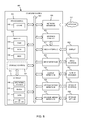
- FIG. 8 shows a diagrammatic representation of one embodiment of a computer system.
- FIG. 9 illustrates another power generation system providing pulsed RF power to a plasma chamber via a matching network, where the pulsed RF power uses a fixed initial RF frequency at a start of each pulse.
- FIG. 10 illustrates yet another power generation system providing pulsed RF power to a plasma chamber via a matching network, where the pulsed RF power uses a fixed initial RF frequency at a start of each pulse.
- pulsed RF power is RF power having a power envelope that is pulsed. In other words, multiple periods of RF power are delivered, followed by a period of no power, followed by another set of period of RF power (or a pulse).
- this disclosure describes systems, methods, and apparatus where an initial RF frequency at the start of each pulse is dictated not by the tuned frequency at an end of a preceding pulse, but by a fixed value that remains the same from pulse to pulse. Further, this initial RF frequency can be determined prior to a processing run using a dummy substrate or other means. While this fixed initial RF frequency will still see some impedance mismatch at the start of each pulse due to unavoidable variations at the start of any pulse, the mismatch will on average be far less than seen in the prior art (e.g., compare FIGS. 2 and 3 ).
- a method for identifying an initial RF frequency that maximizes delivered power to the plasma load at a start of each pulse, as identified during a calibration phase, where a dummy substrate, or no substrate, is in the plasma processing chamber.
- the calibration phase can involve traditional frequency tuning after a start of each pulse, but at the start, the frequency can be tuned from pulse to pulse in order to minimize reflected power or optimize some other characteristic indicative of delivered power.
- This initial RF frequency can then be used as the initial RF frequency for every pulse during a processing phase—or an actual run—where a real substrate is processed in the plasma processing chamber.
- traditional frequency tuning as understood by those of skill in the art is implemented for a remainder of each pulse.
- FIG. 2 illustrates the impedance mismatch that can result when traditional frequency tuning methods are used.
- the pulse on and off states can be seen in the lower of the two plots.
- the frequency at which the RF power is being delivered at any point in time is seen in the upper of the two plots.
- the frequency is tuned in a generally downward trending fashion such that the frequency f 1 is being used when the pulse turns off.
- the next pulse sees f 1 as the initial RF frequency.
- an ideal tuning frequency (as shown by the dotted lines) is at a much higher frequency, and so starting at f 1 leads to a large impedance mismatch (just as starting at f 2 at the next pulse leads to a large impedance mismatch).
- Subsequent tuning during each pulse allows the tuned frequency to approach the ideal tuning frequency, but the initial impedance mismatch is less than ideal.
- FIG. 3 illustrates a reduced impedance mismatch at the start of pulses where a fixed initial RF frequency is used.
- the pulse on and off states can be seen in the lower of the two plots while the frequency at which the RF power is being delivered at any point in time is seen in the upper of the two plots.
- the frequency is tuned in a generally downward trending fashion such that the frequency f 1 is being used when the pulse turns off.
- f 0 is again used, and this pattern repeats for the initial RF frequency of each pulse.
- a fixed initial RF frequency, f 0 can be used for each pulse, where the fixed initial RF frequency, f 0 , has been preselected as an optimal average starting frequency for pulses.
- the result is that the initial RF frequency, f 0 , is much closer to the ideal tuning frequency at a start of each pulse than if the tuned frequency at an end of a previous pulse was carried over to the start of the next pulse (as in FIG. 2 ). This causes far less impedance mismatch at the start of pulses and hence more consistent and accurate processing runs.
- FIG. 1 illustrates a power generation system providing pulsed RF power to a plasma chamber via a matching network, where the pulsed RF power uses a fixed initial RF frequency at a start of each pulse.
- the power generation system 100 can include a power source 110 providing pulsed RF power.
- the power source 110 can provide RF power and an optional switching circuit 116 can pulse the RF power to generate pulsed RF power.
- the frequency of the RF, the frequency of the pulses, and a duty cycle of the pulses can be controlled by a controller 114 (e.g., via one or more logical blocks). Further, the controller 114 can carry out frequency tuning of the pulsed RF power during each pulse.
- the controller 114 can also determine a fixed initial RF frequency, f 0 , and instruct the power source 110 to use this fixed initial RF frequency at a start of each pulse.
- a sensor 112 can sample a characteristic of the pulsed RF power (e.g., reflected power, delivered power, load impedance, plasma density, etc.) on either side of the matching network 104 or at the plasma chamber 108 when a dummy substrate or no substrate is in the plasma chamber 108 and the plasma 106 is ignited (during a calibration phase).
- the sensor 112 can provide these samples to a measurement module 118 of the controller 114 , and the measurement module 118 can prepare the samples for an initial frequency comparison module 120 (e.g., by transforming the samples into a different data form, e.g., an analog-to-digital converter).
- the initial frequency comparison module 120 can compare the samples of the characteristic of the pulsed RF power at a start of each of a plurality of RF pulses to a desired characteristic of the pulsed RF power at a start of each of the plurality of pulses and via this comparison, the initial frequency comparison module 120 can determine an error value.
- a frequency control module 122 of the controller 114 can instruct the power source 110 to adjust the initial RF frequency at a start of each of a plurality of pulses based on the error value from the initial frequency comparison module 120 .
- the frequency control module 122 can instruct the power source 110 to adjust the initial RF frequency at a start of each of a plurality of pulses, where the adjustments are tailored to minimize the error value.
- an initial frequency identification module 124 eventually determines that further adjustments to the frequency of the power source 110 are failing to result in further reduction of the error value, and identifies the latest initial RF frequency as the fixed initial RF frequency to be used during an actual processing run (during a processing phase).
- the initial frequency identification module 124 can identify when adjustment to the initial RF frequency at the start of two or more consecutive pulses fails to result in further reduction in the error value, and can then identify the last initial RF frequency as the fixed initial RF frequency for use during the processing phase.
- the initial frequency identification module 124 determines when two or more consecutive adjustments to the initial RF frequency fail to result in at least a threshold decrease in the error value, and then identifies a last initial RF frequency, or an average of a last few initial RF frequencies, as the fixed initial RF frequency for use during the processing phase. In yet another embodiment, the initial frequency identification module 124 determines that the initial RF frequency has reached a steady state, such that further adjustments to the initial RF frequency for consecutive pulses is not resulting in significant changes to the initial RF frequency or that a magnitude of adjustments to the initial RF frequency from pulse to pulse are consistently below a threshold (e.g., 1% of a magnitude of the initial RF frequency). For instance, where ten consecutive pulses each see less than 1% adjustments to the initial RF frequency, then the initial RF frequency can be deemed to have reached a steady state, and hence can be identified as the fixed initial RF frequency for use during the processing phase.
- a threshold e.g., 1% of a magnitude of the initial RF
- a substrate can be loaded into the plasma chamber 108 and the controller 114 can cause the power source 110 to begin supplying power for the processing phase.
- the controller 114 can instruct the power source 110 to start each pulse using the fixed initial RF frequency, and can then perform real-time frequency tuning for the remainder of each pulse.
- the controller 114 and/or the sensor 112 can be in communication with an optional display 126 and an optional user interface 128 .
- the sensor 112 can send samples of the pulsed RF power, or any characteristic indicative of delivered power (e.g., voltage and current or plasma density, to name two examples), to the display 126 for presentation to a user.
- the controller 114 can send this same information to the display 126 for presentation to a user.
- the controller 114 can receive the samples form the sensor 112 and convert the samples to a data stream that is more easily presentable to a user and then send this data stream to the display 126 for presentation to a user.
- Such displaying of information can merely inform a user, or can be used to take further action.
- the user can use the user interface 128 to provide inputs for controlling the power source 110 .
- the senor 112 , 912 , 1012 (and the display 126 , 926 , 1026 ) can be replaced with an oscilloscope (or an oscilloscope can include the sensor 112 , 912 , 1012 ) to provide feedback to a user regarding the characteristic indicative of delivered power (e.g., reflected power).
- a user may use readings visible on the oscilloscope to manually tune the initial RF frequency until the user identifies a frequency to use as the fixed initial RF frequency during the processing phase.
- the senor 112 , 912 , 1012 is not in direct communication with the controller 114 (e.g., the line connecting sensor 112 , 912 , 1012 with the controller 114 , 914 , 1014 is dotted/dashed and hence optional), and therefore manual analysis of data from the sensor 112 , 912 , 1012 is made followed by manual instructions being provided to the controller 114 , 914 , 1014 to adjust the initial RF frequency or select a last initial RF frequency (or an average of a last number of initial RF frequencies) as the fixed initial RF frequency.
- FIG. 5 illustrates a method of frequency tuning RF pulsed power to a plasma load during a calibration phase.
- the method 500 provides pulsed RF power to a plasma load where the RF has a controllable frequency.
- the pulsed RF power is provided to a plasma load where the plasma operates on a dummy substrate or where no substrate is in the plasma chamber.
- the method 500 sets an initial RF frequency (f n-1 ) at a start of a pulse (Block 502 ) so that the initial RF frequency is applied at a start of a pulse.
- the method 500 tunes the RF frequency to maximize delivered power or some other characteristic indicative of delivered power (Block 506 ) until an end of the pulse (Decision 508 ).
- the method 500 again sets the initial frequency to a different frequency (f n ) in an attempt to minimize an error function for delivered power (e.g., a difference between actual and desired delivered power) (Block 510 ). Power is applied at this new frequency, f n , at the start of the next pulse (Decision 504 ), and then the frequency is tuned to maximize delivered power or another characteristic indicative of delivered power for a remainder of the next pulse (Block 506 ).
- the method 500 again adjusts the initial frequency in an attempt to further minimize the error function for delivered power (Block 510 ). This series of operations continues to repeat until further iterations fail to result in significant reduction to the error function (Decision 512 ), at which point the initial frequency can be identified as the fixed initial RF frequency that is to be used during the processing phase (Block 514 and see FIG. 6 ).
- the tuning for a remainder of each pulse can be automated while in others it can be manual.
- Automated tuning involves a sensor providing samples of a characteristic, and a controller tuning the RF frequency based on the samples of the characteristic.
- Manual operation might see a user observing the samples (e.g., on a display in communication with the sensor or on an oscilloscope directly monitoring the characteristic with or without a separate sensor) and manually adjusting the initial RF frequency at a start of each pulse according to the data that is visible to the user.
- a user cannot tune as rapidly as an automated system, so the user may not adjust the initial RF frequency every pulse, but instead may only be able to adjust the initial RF frequency every thousand pulses. The method will still be effective, and once a fixed initial RF frequency is manually identified, this frequency can be used as a setpoint for a processing phase.
- FIG. 6 illustrates a method of frequency tuning RF pulsed power to a plasma load during a processing phase.
- the method 600 involves providing pulsed RF power to a plasma load, where each pulse comprises RF power having a controllable frequency, and where a plasma having the plasma load processes a substrate in a plasma chamber (e.g., the processing phase).
- the method 600 sets a fixed initial RF frequency to f 0 (Block 606 ), a frequency that is fixed for the start of all pulses.
- the method tunes the RF frequency to maximize delivered power or a characteristic indicative of delivered power (Block 608 ) until an end of the pulse (Decision 610 ).
- the method resets the initial RF frequency to f 0 and repeats for the next pulse.
- a fixed initial RF frequency, f 0 is set at the start of each pulse and is fixed from pulse to pulse regardless as to the frequency tuning that occurs during a remainder of each pulse.
- FIG. 7 illustrates a method of frequency tuning RF pulsed power to a plasma load during both a calibration phase and a processing phase.
- the method 700 involves two phases: a calibration phase and a processing phase.
- the calibration phase identifies a fixed initial RF frequency, f 0 , for pulsed RF power, while the processing phase uses the fixed initial RF frequency, f 0 , at a start of each pulse to process a substrate.
- the method 700 starts by providing pulsed RF power to a plasma to ignite and sustain the plasma in a plasma processing chamber having a dummy substrate or no substrate (Block 702 ) (a start of the calibration phase).
- the method 700 then tunes the initial frequency over the course of multiple RF pulses by repeatedly adjusting the RF frequency at a start of a plurality of consecutive pulses of RF power delivered to the plasma load (Block 704 ).
- the adjusting is performed to optimize a characteristic indicative of delivered power at a start of each pulse as compared from pulse to pulse.
- the method 700 identifies this frequency as the fixed initial RF frequency, f 0 (Block 708 ).
- the method 700 then enters the processing phase, where a substrate is loaded into the plasma processing chamber and an actual processing run is carried out on the substrate.
- the method 700 provides pulsed RF power to the plasma load to ignite and sustain the plasma with the substrate in the chamber, where the initial RF frequency at a start of each pulse is the fixed initial RF frequency, f 0 .
- the remainder of each pulse can involve tuning the frequency of the RF power to minimize a difference between a characteristic of the pulsed RF power and a desired characteristic of the pulsed RF power.
- the methods of tuning can be applied to the matching network.
- the match can be used to tune impedance during each pulse, and the match can return to a same impedance at a start of each pulse.
- the fixed initial impedance can be identified via tuning in a calibration phase where a dummy substrate or no substrate is used.
- FIG. 8 shows a diagrammatic representation of one embodiment of a computer system 800 within which a set of instructions can execute for causing a device to perform or execute any one or more of the aspects and/or methodologies of the present disclosure.
- Controller 114 in FIG. 1 is one implementation of the computer system 800 or can be a component within an implementation of the computer system 800 .
- the components in FIG. 8 are examples only and do not limit the scope of use or functionality of any hardware, software, firmware, embedded logic component, or a combination of two or more such components implementing particular embodiments of this disclosure.
- Some or all of the illustrated components can be part of the computer system 800 .
- the computer system 800 can be a general purpose computer (e.g., a laptop computer) or an embedded logic device (e.g., an FPGA), to name just two non-limiting examples.
- Computer system 800 includes at least a processor 801 such as a central processing unit (CPU) or an FPGA to name two non-limiting examples. Controller 114 in FIG. 1 is one implementation of the processor 801 .
- the computer system 800 may also comprise a memory 803 and a storage 808 , both communicating with each other, and with other components, via a bus 840 .
- the bus 840 may also link a display 832 , one or more input devices 833 (which may, for example, include a keypad, a keyboard, a mouse, a stylus, etc.), one or more output devices 834 , one or more storage devices 835 , and various non-transitory, tangible computer-readable storage media 836 with each other and with one or more of the processor 801 , the memory 803 , and the storage 808 . All of these elements may interface directly or via one or more interfaces or adaptors to the bus 840 .
- the various non-transitory, tangible computer-readable storage media 836 can interface with the bus 840 via storage medium interface 826 .
- Computer system 800 may have any suitable physical form, including but not limited to one or more integrated circuits (ICs), printed circuit boards (PCBs), mobile handheld devices (such as mobile telephones or PDAs), laptop or notebook computers, distributed computer systems, computing grids, or servers.
- ICs integrated circuits
- PCBs printed circuit boards
- Processor(s) 801 (or central processing unit(s) (CPU(s))) optionally contains a cache memory unit 802 for temporary local storage of instructions, data, or computer addresses.
- Processor(s) 801 are configured to assist in execution of computer-readable instructions stored on at least one non-transitory, tangible computer-readable storage medium.
- Computer system 800 may provide functionality as a result of the processor(s) 801 executing software embodied in one or more non-transitory, tangible computer-readable storage media, such as memory 803 , storage 808 , storage devices 835 , and/or storage medium 836 (e.g., read only memory (ROM)). For instance, the method 500 in FIG. 5 or the method 600 in FIG.
- ROM read only memory
- the non-transitory, tangible computer-readable storage media may store software that implements particular embodiments, such as the methods 500 , 600 , and 700 , and processor(s) 801 may execute the software.
- Memory 803 may read the software from one or more other non-transitory, tangible computer-readable storage media (such as mass storage device(s) 835 , 836 ) or from one or more other sources through a suitable interface, such as network interface 820 .
- the software may cause processor(s) 801 to carry out one or more processes or one or more steps of one or more processes described or illustrated herein.
- Carrying out such processes or steps may include defining data structures stored in memory 803 and modifying the data structures as directed by the software.
- an FPGA can store instructions for carrying out functionality as described in this disclosure (e.g., the methods 500 , 600 , and 700 ).
- firmware includes instructions for carrying out functionality as described in this disclosure (e.g., the methods 500 , 600 , and 700 ).
- the memory 803 may include various components (e.g., non-transitory, tangible computer-readable storage media) including, but not limited to, a random access memory component (e.g., RAM 804 ) (e.g., a static RAM “SRAM”, a dynamic RAM “DRAM, etc.), a read-only component (e.g., ROM 805 ), and any combinations thereof.
- ROM 805 may act to communicate data and instructions unidirectionally to processor(s) 801
- RAM 804 may act to communicate data and instructions bidirectionally with processor(s) 801 .
- ROM 805 and RAM 804 may include any suitable non-transitory, tangible computer-readable storage media described below.
- ROM 805 and RAM 804 include non-transitory, tangible computer-readable storage media for carrying out the methods 500 , 600 , and 700 .
- a basic input/output system 806 (BIOS), including basic routines that help to transfer information between elements within computer system 800 , such as during start-up, may be stored in the memory 803 .
- Fixed storage 808 is connected bidirectionally to processor(s) 801 , optionally through storage control unit 807 .
- Fixed storage 808 provides additional data storage capacity and may also include any suitable non-transitory, tangible computer-readable media described herein.
- Storage 808 may be used to store operating system 809 , EXECs 810 (executables), data 811 , API applications 812 (application programs), and the like.
- the storage 808 could be implemented for storage of the fixed initial RF frequency, f 0 , as described in FIGS. 1-7 and 9-10 .
- storage 808 is a secondary storage medium (such as a hard disk) that is slower than primary storage (e.g., memory 803 ).
- Storage 808 can also include an optical disk drive, a solid-state memory device (e.g., flash-based systems), or a combination of any of the above.
- Information in storage 808 may, in appropriate cases, be incorporated as virtual memory in memory 803 .
- storage device(s) 835 may be removably interfaced with computer system 800 (e.g., via an external port connector (not shown)) via a storage device interface 825 .
- storage device(s) 835 and an associated machine-readable medium may provide nonvolatile and/or volatile storage of machine-readable instructions, data structures, program modules, and/or other data for the computer system 800 .
- software may reside, completely or partially, within a machine-readable medium on storage device(s) 835 .
- software may reside, completely or partially, within processor(s) 801 .
- Bus 840 connects a wide variety of subsystems.
- reference to a bus may encompass one or more digital signal lines serving a common function, where appropriate.
- Bus 840 may be any of several types of bus structures including, but not limited to, a memory bus, a memory controller, a peripheral bus, a local bus, and any combinations thereof, using any of a variety of bus architectures.
- such architectures include an Industry Standard Architecture (ISA) bus, an Enhanced ISA (EISA) bus, a Micro Channel Architecture (MCA) bus, a Video Electronics Standards Association local bus (VLB), a Peripheral Component Interconnect (PCI) bus, a PCI-Express (PCI-X) bus, an Accelerated Graphics Port (AGP) bus, HyperTransport (HTX) bus, serial advanced technology attachment (SATA) bus, and any combinations thereof.
- ISA Industry Standard Architecture
- EISA Enhanced ISA
- MCA Micro Channel Architecture
- VLB Video Electronics Standards Association local bus
- PCI Peripheral Component Interconnect
- PCI-X PCI-Express
- AGP Accelerated Graphics Port
- HTTP HyperTransport
- SATA serial advanced technology attachment
- Input device(s) 833 may be interfaced to bus 840 via any of a variety of input interfaces 823 (e.g., input interface 823 ) including, but not limited to, serial, parallel, game port, USB, FIREWIRE, THUNDERBOLT, or any combination of the above.
- computer system 800 when computer system 800 is connected to network 830 , computer system 800 may communicate with other devices, such as mobile devices and enterprise systems, connected to network 830 . Communications to and from computer system 800 may be sent through network interface 820 .
- network interface 820 may receive incoming communications (such as requests or responses from other devices) in the form of one or more packets (such as Internet Protocol (IP) packets) from network 830 , and computer system 800 may store the incoming communications in memory 803 for processing.
- Computer system 800 may similarly store outgoing communications (such as requests or responses to other devices) in the form of one or more packets in memory 803 and communicated to network 830 from network interface 820 .
- Processor(s) 801 may access these communication packets stored in memory 803 for processing.
- Examples of the network interface 820 include, but are not limited to, a network interface card, a modem, and any combination thereof.
- Examples of a network 830 or network segment 830 include, but are not limited to, a wide area network (WAN) (e.g., the Internet, an enterprise network), a local area network (LAN) (e.g., a network associated with an office, a building, a campus or other relatively small geographic space), a telephone network, a direct connection between two computing devices, and any combinations thereof.
- WAN wide area network
- LAN local area network
- a network, such as network 830 may employ a wired and/or a wireless mode of communication. In general, any network topology may be used.
- a display 832 can be displayed through a display 832 .
- a display 832 include, but are not limited to, a liquid crystal display (LCD), an organic liquid crystal display (OLED), a cathode ray tube (CRT), a plasma display, and any combinations thereof.
- the display 832 can interface to the processor(s) 801 , memory 803 , and fixed storage 808 , as well as other devices, such as input device(s) 833 , via the bus 840 .
- the display 832 is linked to the bus 840 via a video interface 822 , and transport of data between the display 832 and the bus 840 can be controlled via the graphics control 821 .
- computer system 800 may include one or more other peripheral output devices 834 including, but not limited to, an audio speaker, a printer, and any combinations thereof.
- peripheral output devices may be connected to the bus 840 via an output interface 824 .
- Examples of an output interface 824 include, but are not limited to, a serial port, a parallel connection, a USB port, a FIREWIRE port, a THUNDERBOLT port, and any combinations thereof.
- computer system 800 may provide functionality as a result of logic hardwired or otherwise embodied in a circuit, which may operate in place of or together with software to execute one or more processes or one or more steps of one or more processes described or illustrated herein.
- Reference to software in this disclosure may encompass logic, and reference to logic may encompass software.
- reference to a non-transitory, tangible computer-readable medium may encompass a circuit (such as an IC) storing software for execution, a circuit embodying logic for execution, or both, where appropriate.
- the present disclosure encompasses any suitable combination of hardware, software, or both.
- the same reference characters are used to refer to terminals, signal lines, wires, etc. and their corresponding signals.
- the terms “signal,” “wire,” “connection,” “terminal,” and “pin” may be used interchangeably, from time-to-time, within the this specification.
- the terms “signal,” “wire,” or the like can represent one or more signals, e.g., the conveyance of a single bit through a single wire or the conveyance of multiple parallel bits through multiple parallel wires.
- each wire or signal may represent bi-directional communication between two, or more, components connected by a signal or wire as the case may be.
- DSP digital signal processor
- ASIC application specific integrated circuit
- FPGA field programmable gate array
- a general purpose processor may be a microprocessor, but in the alternative, the processor may be any conventional processor, controller, or microcontroller.
- a processor may also be implemented as a combination of computing devices, e.g., a combination of a DSP and a microprocessor, a plurality of microprocessors, one or more microprocessors in conjunction with a DSP core, or any other such configuration.
- the steps of a method or algorithm described in connection with the embodiments disclosed herein may be embodied directly in hardware, in a software module executed by a processor, a software module implemented as digital logic devices, or in a combination of these.
- a software module may reside in RAM memory, flash memory, ROM memory, EPROM memory, EEPROM memory, registers, hard disk, a removable disk, a CD-ROM, or any other form of non-transitory, tangible computer-readable storage medium known in the art.
- An exemplary non-transitory, tangible computer-readable storage medium is coupled to the processor such that the processor can read information from, and write information to, the non-transitory, tangible computer-readable storage medium.
- non-transitory, tangible computer-readable storage medium may be integral to the processor.
- the processor and the non-transitory, tangible computer-readable storage medium may reside in an ASIC.
- the ASIC may reside in a user terminal.
- the processor and the non-transitory, tangible computer-readable storage medium may reside as discrete components in a user terminal.
- a software module may be implemented as digital logic components such as those in an FPGA once programmed with the software module.
Landscapes
- Physics & Mathematics (AREA)
- Engineering & Computer Science (AREA)
- Plasma & Fusion (AREA)
- Chemical & Material Sciences (AREA)
- Analytical Chemistry (AREA)
- Electromagnetism (AREA)
- Spectroscopy & Molecular Physics (AREA)
- Plasma Technology (AREA)
- Chemical Vapour Deposition (AREA)
Abstract
Description
Claims (17)
Priority Applications (5)
| Application Number | Priority Date | Filing Date | Title |
|---|---|---|---|
| US14/320,268 US9544987B2 (en) | 2014-06-30 | 2014-06-30 | Frequency tuning for pulsed radio frequency plasma processing |
| TW104120296A TWI680698B (en) | 2014-06-30 | 2015-06-24 | Frequency tuning for pulsed radio frequency plasma processing |
| PCT/US2015/037607 WO2016003758A1 (en) | 2014-06-30 | 2015-06-25 | Frequency tuning for pulsed radio frequency plasma processing |
| US15/403,021 US9711331B2 (en) | 2014-06-30 | 2017-01-10 | Frequency tuning for pulsed radio frequency plasma processing |
| US15/499,567 US9852890B2 (en) | 2014-06-30 | 2017-04-27 | Frequency tuning for pulsed radio frequency plasma processing |
Applications Claiming Priority (1)
| Application Number | Priority Date | Filing Date | Title |
|---|---|---|---|
| US14/320,268 US9544987B2 (en) | 2014-06-30 | 2014-06-30 | Frequency tuning for pulsed radio frequency plasma processing |
Related Child Applications (1)
| Application Number | Title | Priority Date | Filing Date |
|---|---|---|---|
| US15/403,021 Continuation US9711331B2 (en) | 2014-06-30 | 2017-01-10 | Frequency tuning for pulsed radio frequency plasma processing |
Publications (2)
| Publication Number | Publication Date |
|---|---|
| US20150382442A1 US20150382442A1 (en) | 2015-12-31 |
| US9544987B2 true US9544987B2 (en) | 2017-01-10 |
Family
ID=54932136
Family Applications (3)
| Application Number | Title | Priority Date | Filing Date |
|---|---|---|---|
| US14/320,268 Active 2034-07-21 US9544987B2 (en) | 2014-06-30 | 2014-06-30 | Frequency tuning for pulsed radio frequency plasma processing |
| US15/403,021 Active US9711331B2 (en) | 2014-06-30 | 2017-01-10 | Frequency tuning for pulsed radio frequency plasma processing |
| US15/499,567 Active US9852890B2 (en) | 2014-06-30 | 2017-04-27 | Frequency tuning for pulsed radio frequency plasma processing |
Family Applications After (2)
| Application Number | Title | Priority Date | Filing Date |
|---|---|---|---|
| US15/403,021 Active US9711331B2 (en) | 2014-06-30 | 2017-01-10 | Frequency tuning for pulsed radio frequency plasma processing |
| US15/499,567 Active US9852890B2 (en) | 2014-06-30 | 2017-04-27 | Frequency tuning for pulsed radio frequency plasma processing |
Country Status (3)
| Country | Link |
|---|---|
| US (3) | US9544987B2 (en) |
| TW (1) | TWI680698B (en) |
| WO (1) | WO2016003758A1 (en) |
Cited By (50)
| Publication number | Priority date | Publication date | Assignee | Title |
|---|---|---|---|---|
| US20180053633A1 (en) * | 2015-05-05 | 2018-02-22 | Trumpf Huettinger Sp. Z O. O. | Plasma Impedance Matching for Supplying RF Power to a Plasma Load |
| US10009028B2 (en) | 2016-09-30 | 2018-06-26 | Lam Research Corporation | Frequency and match tuning in one state and frequency tuning in the other state |
| US20190013182A1 (en) * | 2017-07-07 | 2019-01-10 | Advanced Energy Industries, Inc. | Inter-period control system for plasma power delivery system and method of operating the same |
| US10791617B2 (en) | 2018-05-10 | 2020-09-29 | Applied Materials, Inc. | Method of controlling ion energy distribution using a pulse generator with a current-return output stage |
| US20210166917A1 (en) * | 2017-07-07 | 2021-06-03 | Advanced Energy Industries, Inc. | Inter-period control for passive power distribution of multiple electrode inductive plasma source |
| US20210249228A1 (en) * | 2017-07-07 | 2021-08-12 | Advanced Energy Industries, Inc. | Inter-period control system for plasma power delivery system and method of operating same |
| US11107661B2 (en) | 2019-07-09 | 2021-08-31 | COMET Technologies USA, Inc. | Hybrid matching network topology |
| US11114279B2 (en) | 2019-06-28 | 2021-09-07 | COMET Technologies USA, Inc. | Arc suppression device for plasma processing equipment |
| US11290080B2 (en) | 2017-11-29 | 2022-03-29 | COMET Technologies USA, Inc. | Retuning for impedance matching network control |
| US11373844B2 (en) | 2020-09-28 | 2022-06-28 | COMET Technologies USA, Inc. | Systems and methods for repetitive tuning of matching networks |
| US11462389B2 (en) | 2020-07-31 | 2022-10-04 | Applied Materials, Inc. | Pulsed-voltage hardware assembly for use in a plasma processing system |
| US11476145B2 (en) | 2018-11-20 | 2022-10-18 | Applied Materials, Inc. | Automatic ESC bias compensation when using pulsed DC bias |
| US11476090B1 (en) | 2021-08-24 | 2022-10-18 | Applied Materials, Inc. | Voltage pulse time-domain multiplexing |
| US11495470B1 (en) | 2021-04-16 | 2022-11-08 | Applied Materials, Inc. | Method of enhancing etching selectivity using a pulsed plasma |
| US11508554B2 (en) | 2019-01-24 | 2022-11-22 | Applied Materials, Inc. | High voltage filter assembly |
| US11521832B2 (en) | 2020-01-10 | 2022-12-06 | COMET Technologies USA, Inc. | Uniformity control for radio frequency plasma processing systems |
| US11527385B2 (en) | 2021-04-29 | 2022-12-13 | COMET Technologies USA, Inc. | Systems and methods for calibrating capacitors of matching networks |
| US11569066B2 (en) | 2021-06-23 | 2023-01-31 | Applied Materials, Inc. | Pulsed voltage source for plasma processing applications |
| US11596309B2 (en) | 2019-07-09 | 2023-03-07 | COMET Technologies USA, Inc. | Hybrid matching network topology |
| US11605527B2 (en) | 2020-01-20 | 2023-03-14 | COMET Technologies USA, Inc. | Pulsing control match network |
| US11657980B1 (en) | 2022-05-09 | 2023-05-23 | COMET Technologies USA, Inc. | Dielectric fluid variable capacitor |
| US11670488B2 (en) | 2020-01-10 | 2023-06-06 | COMET Technologies USA, Inc. | Fast arc detecting match network |
| US11791138B2 (en) | 2021-05-12 | 2023-10-17 | Applied Materials, Inc. | Automatic electrostatic chuck bias compensation during plasma processing |
| US11798790B2 (en) | 2020-11-16 | 2023-10-24 | Applied Materials, Inc. | Apparatus and methods for controlling ion energy distribution |
| US11810760B2 (en) | 2021-06-16 | 2023-11-07 | Applied Materials, Inc. | Apparatus and method of ion current compensation |
| US11830708B2 (en) | 2020-01-10 | 2023-11-28 | COMET Technologies USA, Inc. | Inductive broad-band sensors for electromagnetic waves |
| US11887820B2 (en) | 2020-01-10 | 2024-01-30 | COMET Technologies USA, Inc. | Sector shunts for plasma-based wafer processing systems |
| US11901157B2 (en) | 2020-11-16 | 2024-02-13 | Applied Materials, Inc. | Apparatus and methods for controlling ion energy distribution |
| US11923175B2 (en) | 2021-07-28 | 2024-03-05 | COMET Technologies USA, Inc. | Systems and methods for variable gain tuning of matching networks |
| US11948780B2 (en) | 2021-05-12 | 2024-04-02 | Applied Materials, Inc. | Automatic electrostatic chuck bias compensation during plasma processing |
| US11961711B2 (en) | 2020-01-20 | 2024-04-16 | COMET Technologies USA, Inc. | Radio frequency match network and generator |
| US11967483B2 (en) | 2021-06-02 | 2024-04-23 | Applied Materials, Inc. | Plasma excitation with ion energy control |
| US11972924B2 (en) | 2022-06-08 | 2024-04-30 | Applied Materials, Inc. | Pulsed voltage source for plasma processing applications |
| US12002611B2 (en) | 2019-08-28 | 2024-06-04 | COMET Technologies USA, Inc. | High power low frequency coils |
| US12027351B2 (en) | 2020-01-10 | 2024-07-02 | COMET Technologies USA, Inc. | Plasma non-uniformity detection |
| US12040139B2 (en) | 2022-05-09 | 2024-07-16 | COMET Technologies USA, Inc. | Variable capacitor with linear impedance and high voltage breakdown |
| US12051549B2 (en) | 2022-08-02 | 2024-07-30 | COMET Technologies USA, Inc. | Coaxial variable capacitor |
| US12057296B2 (en) | 2021-02-22 | 2024-08-06 | COMET Technologies USA, Inc. | Electromagnetic field sensing device |
| US12057292B2 (en) | 2019-01-22 | 2024-08-06 | Applied Materials, Inc. | Feedback loop for controlling a pulsed voltage waveform |
| US12106938B2 (en) | 2021-09-14 | 2024-10-01 | Applied Materials, Inc. | Distortion current mitigation in a radio frequency plasma processing chamber |
| US12111341B2 (en) | 2022-10-05 | 2024-10-08 | Applied Materials, Inc. | In-situ electric field detection method and apparatus |
| US12132435B2 (en) | 2022-10-27 | 2024-10-29 | COMET Technologies USA, Inc. | Method for repeatable stepper motor homing |
| US12198966B2 (en) | 2017-09-20 | 2025-01-14 | Applied Materials, Inc. | Substrate support with multiple embedded electrodes |
| US12243717B2 (en) | 2022-04-04 | 2025-03-04 | COMET Technologies USA, Inc. | Variable reactance device having isolated gate drive power supplies |
| US12272524B2 (en) | 2022-09-19 | 2025-04-08 | Applied Materials, Inc. | Wideband variable impedance load for high volume manufacturing qualification and on-site diagnostics |
| US12283463B2 (en) | 2019-04-29 | 2025-04-22 | Lam Research Corporation | Systems and methods for multi-level pulsing in RF plasma tools |
| US12288673B2 (en) | 2017-11-29 | 2025-04-29 | COMET Technologies USA, Inc. | Retuning for impedance matching network control |
| US12315732B2 (en) | 2022-06-10 | 2025-05-27 | Applied Materials, Inc. | Method and apparatus for etching a semiconductor substrate in a plasma etch chamber |
| US12525433B2 (en) | 2021-06-09 | 2026-01-13 | Applied Materials, Inc. | Method and apparatus to reduce feature charging in plasma processing chamber |
| US12586768B2 (en) | 2022-08-10 | 2026-03-24 | Applied Materials, Inc. | Pulsed voltage compensation for plasma processing applications |
Families Citing this family (15)
| Publication number | Priority date | Publication date | Assignee | Title |
|---|---|---|---|---|
| US9627186B2 (en) * | 2014-08-29 | 2017-04-18 | Lam Research Corporation | System, method and apparatus for using optical data to monitor RF generator operations |
| CN110291408B (en) | 2017-02-16 | 2022-12-13 | 应用材料公司 | Voltage-current probe for measuring radio frequency electric power in high temperature environment and calibration method thereof |
| US10679825B2 (en) * | 2017-11-15 | 2020-06-09 | Lam Research Corporation | Systems and methods for applying frequency and match tuning in a non-overlapping manner for processing substrate |
| US11209478B2 (en) * | 2018-04-03 | 2021-12-28 | Applied Materials, Inc. | Pulse system verification |
| CN110504149B (en) * | 2018-05-17 | 2022-04-22 | 北京北方华创微电子装备有限公司 | Pulse modulation system and method of radio frequency power supply |
| US10854427B2 (en) * | 2018-08-30 | 2020-12-01 | Applied Materials, Inc. | Radio frequency (RF) pulsing impedance tuning with multiplier mode |
| CN111293022B (en) * | 2018-12-07 | 2023-01-24 | 中微半导体设备(上海)股份有限公司 | Impedance matching method and device for pulsed radio frequency plasma |
| KR102348338B1 (en) * | 2019-02-07 | 2022-01-06 | 엠케이에스코리아 유한회사 | The Driving Frequency Control Method of The Pulsed Frequency Variable RF Generator |
| WO2020231881A1 (en) * | 2019-05-10 | 2020-11-19 | Lam Research Corporation | Method and system for automated frequency tuning of radiofrequency (rf) signal generator for multi-level rf power pulsing |
| US11315757B2 (en) * | 2019-08-13 | 2022-04-26 | Mks Instruments, Inc. | Method and apparatus to enhance sheath formation, evolution and pulse to pulse stability in RF powered plasma applications |
| TWI899187B (en) * | 2020-03-19 | 2025-10-01 | 美商蘭姆研究公司 | Substrate processing system |
| US12525441B2 (en) | 2021-06-09 | 2026-01-13 | Applied Materials, Inc. | Plasma chamber and chamber component cleaning methods |
| US12148595B2 (en) | 2021-06-09 | 2024-11-19 | Applied Materials, Inc. | Plasma uniformity control in pulsed DC plasma chamber |
| US11694876B2 (en) | 2021-12-08 | 2023-07-04 | Applied Materials, Inc. | Apparatus and method for delivering a plurality of waveform signals during plasma processing |
| US12567562B2 (en) | 2022-12-21 | 2026-03-03 | Advanced Energy Industries, Inc. | Compensation of impedance modulation in a plasma generator by frequency sweep |
Citations (6)
| Publication number | Priority date | Publication date | Assignee | Title |
|---|---|---|---|---|
| US6383554B1 (en) * | 2000-09-05 | 2002-05-07 | National Science Council | Process for fabricating plasma with feedback control on plasma density |
| US6472822B1 (en) * | 2000-04-28 | 2002-10-29 | Applied Materials, Inc. | Pulsed RF power delivery for plasma processing |
| US20090237170A1 (en) * | 2008-03-23 | 2009-09-24 | Van Zyl Gideon J | Method and apparatus for advanced frequency tuning |
| WO2013099133A1 (en) | 2011-12-27 | 2013-07-04 | 東京エレクトロン株式会社 | Plasma treatment apparatus |
| US20130214683A1 (en) * | 2012-02-22 | 2013-08-22 | Lam Research Corporation | Impedance-Based Adjustment of Power and Frequency |
| US20130222055A1 (en) * | 2012-02-23 | 2013-08-29 | Mks Instruments, Inc. | Feedback Control And Coherency Of Multiple Power Supplies In Radio Frequency Power Delivery Systems For Pulsed Mode Schemes in Thin Film Processing |
-
2014
- 2014-06-30 US US14/320,268 patent/US9544987B2/en active Active
-
2015
- 2015-06-24 TW TW104120296A patent/TWI680698B/en active
- 2015-06-25 WO PCT/US2015/037607 patent/WO2016003758A1/en not_active Ceased
-
2017
- 2017-01-10 US US15/403,021 patent/US9711331B2/en active Active
- 2017-04-27 US US15/499,567 patent/US9852890B2/en active Active
Patent Citations (7)
| Publication number | Priority date | Publication date | Assignee | Title |
|---|---|---|---|---|
| US6472822B1 (en) * | 2000-04-28 | 2002-10-29 | Applied Materials, Inc. | Pulsed RF power delivery for plasma processing |
| US6383554B1 (en) * | 2000-09-05 | 2002-05-07 | National Science Council | Process for fabricating plasma with feedback control on plasma density |
| US20090237170A1 (en) * | 2008-03-23 | 2009-09-24 | Van Zyl Gideon J | Method and apparatus for advanced frequency tuning |
| WO2013099133A1 (en) | 2011-12-27 | 2013-07-04 | 東京エレクトロン株式会社 | Plasma treatment apparatus |
| US20140361690A1 (en) * | 2011-12-27 | 2014-12-11 | Tokyo Electron Limited | Plasma processing apparatus |
| US20130214683A1 (en) * | 2012-02-22 | 2013-08-22 | Lam Research Corporation | Impedance-Based Adjustment of Power and Frequency |
| US20130222055A1 (en) * | 2012-02-23 | 2013-08-29 | Mks Instruments, Inc. | Feedback Control And Coherency Of Multiple Power Supplies In Radio Frequency Power Delivery Systems For Pulsed Mode Schemes in Thin Film Processing |
Non-Patent Citations (1)
| Title |
|---|
| Rabbini, Firoozeh, "International Search Report and Written Opinion re Application No. PCT/US2015/037607", Sep. 21, 2015, p. 5 Published in: AU. |
Cited By (71)
| Publication number | Priority date | Publication date | Assignee | Title |
|---|---|---|---|---|
| US10410835B2 (en) * | 2015-05-05 | 2019-09-10 | Trumpf Huettinger Sp. Z O. O. | Plasma impedance matching for supplying RF power to a plasma load |
| US20180053633A1 (en) * | 2015-05-05 | 2018-02-22 | Trumpf Huettinger Sp. Z O. O. | Plasma Impedance Matching for Supplying RF Power to a Plasma Load |
| US10009028B2 (en) | 2016-09-30 | 2018-06-26 | Lam Research Corporation | Frequency and match tuning in one state and frequency tuning in the other state |
| US20210287880A1 (en) * | 2017-07-07 | 2021-09-16 | Advanced Energy Industries, Inc. | Inter-period control system for plasma power delivery system and method of operating the same |
| US11615943B2 (en) * | 2017-07-07 | 2023-03-28 | Advanced Energy Industries, Inc. | Inter-period control for passive power distribution of multiple electrode inductive plasma source |
| US10861677B2 (en) * | 2017-07-07 | 2020-12-08 | Advanced Energy Industries, Inc. | Inter-period control system for plasma power delivery system and method of operating the same |
| US20210166917A1 (en) * | 2017-07-07 | 2021-06-03 | Advanced Energy Industries, Inc. | Inter-period control for passive power distribution of multiple electrode inductive plasma source |
| US20210249228A1 (en) * | 2017-07-07 | 2021-08-12 | Advanced Energy Industries, Inc. | Inter-period control system for plasma power delivery system and method of operating same |
| US20190013182A1 (en) * | 2017-07-07 | 2019-01-10 | Advanced Energy Industries, Inc. | Inter-period control system for plasma power delivery system and method of operating the same |
| US12573591B2 (en) * | 2017-07-07 | 2026-03-10 | Advanced Energy Industries, Inc. | Inter-period control system for plasma power delivery system and method of operating same |
| US11610763B2 (en) * | 2017-07-07 | 2023-03-21 | Advanced Energy Industries, Inc. | Inter-period control system for plasma power delivery system and method of operating the same |
| US11651939B2 (en) * | 2017-07-07 | 2023-05-16 | Advanced Energy Industries, Inc. | Inter-period control system for plasma power delivery system and method of operating same |
| US11450510B2 (en) * | 2017-07-07 | 2022-09-20 | Advanced Energy Industries, Inc. | Inter-period control system for plasma power delivery system and method of operating same |
| US12198966B2 (en) | 2017-09-20 | 2025-01-14 | Applied Materials, Inc. | Substrate support with multiple embedded electrodes |
| US11290080B2 (en) | 2017-11-29 | 2022-03-29 | COMET Technologies USA, Inc. | Retuning for impedance matching network control |
| US12288673B2 (en) | 2017-11-29 | 2025-04-29 | COMET Technologies USA, Inc. | Retuning for impedance matching network control |
| US11284500B2 (en) | 2018-05-10 | 2022-03-22 | Applied Materials, Inc. | Method of controlling ion energy distribution using a pulse generator |
| US10791617B2 (en) | 2018-05-10 | 2020-09-29 | Applied Materials, Inc. | Method of controlling ion energy distribution using a pulse generator with a current-return output stage |
| US11476145B2 (en) | 2018-11-20 | 2022-10-18 | Applied Materials, Inc. | Automatic ESC bias compensation when using pulsed DC bias |
| US12057292B2 (en) | 2019-01-22 | 2024-08-06 | Applied Materials, Inc. | Feedback loop for controlling a pulsed voltage waveform |
| US11508554B2 (en) | 2019-01-24 | 2022-11-22 | Applied Materials, Inc. | High voltage filter assembly |
| US12283463B2 (en) | 2019-04-29 | 2025-04-22 | Lam Research Corporation | Systems and methods for multi-level pulsing in RF plasma tools |
| US11114279B2 (en) | 2019-06-28 | 2021-09-07 | COMET Technologies USA, Inc. | Arc suppression device for plasma processing equipment |
| US11972928B2 (en) | 2019-06-28 | 2024-04-30 | COMET Technologies USA, Inc. | Method and system for plasma processing arc suppression |
| US11574799B2 (en) | 2019-06-28 | 2023-02-07 | COMET Technologies USA, Inc. | Arc suppression device for plasma processing equipment |
| US11596309B2 (en) | 2019-07-09 | 2023-03-07 | COMET Technologies USA, Inc. | Hybrid matching network topology |
| US11107661B2 (en) | 2019-07-09 | 2021-08-31 | COMET Technologies USA, Inc. | Hybrid matching network topology |
| US12002611B2 (en) | 2019-08-28 | 2024-06-04 | COMET Technologies USA, Inc. | High power low frequency coils |
| US11521832B2 (en) | 2020-01-10 | 2022-12-06 | COMET Technologies USA, Inc. | Uniformity control for radio frequency plasma processing systems |
| US12027351B2 (en) | 2020-01-10 | 2024-07-02 | COMET Technologies USA, Inc. | Plasma non-uniformity detection |
| US11670488B2 (en) | 2020-01-10 | 2023-06-06 | COMET Technologies USA, Inc. | Fast arc detecting match network |
| US11887820B2 (en) | 2020-01-10 | 2024-01-30 | COMET Technologies USA, Inc. | Sector shunts for plasma-based wafer processing systems |
| US11830708B2 (en) | 2020-01-10 | 2023-11-28 | COMET Technologies USA, Inc. | Inductive broad-band sensors for electromagnetic waves |
| US11605527B2 (en) | 2020-01-20 | 2023-03-14 | COMET Technologies USA, Inc. | Pulsing control match network |
| US11961711B2 (en) | 2020-01-20 | 2024-04-16 | COMET Technologies USA, Inc. | Radio frequency match network and generator |
| US11776789B2 (en) | 2020-07-31 | 2023-10-03 | Applied Materials, Inc. | Plasma processing assembly using pulsed-voltage and radio-frequency power |
| US11848176B2 (en) | 2020-07-31 | 2023-12-19 | Applied Materials, Inc. | Plasma processing using pulsed-voltage and radio-frequency power |
| US11462389B2 (en) | 2020-07-31 | 2022-10-04 | Applied Materials, Inc. | Pulsed-voltage hardware assembly for use in a plasma processing system |
| US11462388B2 (en) | 2020-07-31 | 2022-10-04 | Applied Materials, Inc. | Plasma processing assembly using pulsed-voltage and radio-frequency power |
| US12237148B2 (en) | 2020-07-31 | 2025-02-25 | Applied Materials, Inc. | Plasma processing assembly using pulsed-voltage and radio-frequency power |
| US11373844B2 (en) | 2020-09-28 | 2022-06-28 | COMET Technologies USA, Inc. | Systems and methods for repetitive tuning of matching networks |
| US11798790B2 (en) | 2020-11-16 | 2023-10-24 | Applied Materials, Inc. | Apparatus and methods for controlling ion energy distribution |
| US12183557B2 (en) | 2020-11-16 | 2024-12-31 | Applied Materials, Inc. | Apparatus and methods for controlling ion energy distribution |
| US11901157B2 (en) | 2020-11-16 | 2024-02-13 | Applied Materials, Inc. | Apparatus and methods for controlling ion energy distribution |
| US12057296B2 (en) | 2021-02-22 | 2024-08-06 | COMET Technologies USA, Inc. | Electromagnetic field sensing device |
| US11495470B1 (en) | 2021-04-16 | 2022-11-08 | Applied Materials, Inc. | Method of enhancing etching selectivity using a pulsed plasma |
| US11527385B2 (en) | 2021-04-29 | 2022-12-13 | COMET Technologies USA, Inc. | Systems and methods for calibrating capacitors of matching networks |
| US11791138B2 (en) | 2021-05-12 | 2023-10-17 | Applied Materials, Inc. | Automatic electrostatic chuck bias compensation during plasma processing |
| US11948780B2 (en) | 2021-05-12 | 2024-04-02 | Applied Materials, Inc. | Automatic electrostatic chuck bias compensation during plasma processing |
| US12347647B2 (en) | 2021-06-02 | 2025-07-01 | Applied Materials, Inc. | Plasma excitation with ion energy control |
| US11967483B2 (en) | 2021-06-02 | 2024-04-23 | Applied Materials, Inc. | Plasma excitation with ion energy control |
| US12525433B2 (en) | 2021-06-09 | 2026-01-13 | Applied Materials, Inc. | Method and apparatus to reduce feature charging in plasma processing chamber |
| US11810760B2 (en) | 2021-06-16 | 2023-11-07 | Applied Materials, Inc. | Apparatus and method of ion current compensation |
| US11887813B2 (en) | 2021-06-23 | 2024-01-30 | Applied Materials, Inc. | Pulsed voltage source for plasma processing |
| US11569066B2 (en) | 2021-06-23 | 2023-01-31 | Applied Materials, Inc. | Pulsed voltage source for plasma processing applications |
| US12125673B2 (en) | 2021-06-23 | 2024-10-22 | Applied Materials, Inc. | Pulsed voltage source for plasma processing applications |
| US11923175B2 (en) | 2021-07-28 | 2024-03-05 | COMET Technologies USA, Inc. | Systems and methods for variable gain tuning of matching networks |
| US11476090B1 (en) | 2021-08-24 | 2022-10-18 | Applied Materials, Inc. | Voltage pulse time-domain multiplexing |
| US12261019B2 (en) | 2021-08-24 | 2025-03-25 | Applied Materials, Inc. | Voltage pulse time-domain multiplexing |
| US12106938B2 (en) | 2021-09-14 | 2024-10-01 | Applied Materials, Inc. | Distortion current mitigation in a radio frequency plasma processing chamber |
| US12243717B2 (en) | 2022-04-04 | 2025-03-04 | COMET Technologies USA, Inc. | Variable reactance device having isolated gate drive power supplies |
| US11657980B1 (en) | 2022-05-09 | 2023-05-23 | COMET Technologies USA, Inc. | Dielectric fluid variable capacitor |
| US12040139B2 (en) | 2022-05-09 | 2024-07-16 | COMET Technologies USA, Inc. | Variable capacitor with linear impedance and high voltage breakdown |
| US11972924B2 (en) | 2022-06-08 | 2024-04-30 | Applied Materials, Inc. | Pulsed voltage source for plasma processing applications |
| US12368020B2 (en) | 2022-06-08 | 2025-07-22 | Applied Materials, Inc. | Pulsed voltage source for plasma processing applications |
| US12315732B2 (en) | 2022-06-10 | 2025-05-27 | Applied Materials, Inc. | Method and apparatus for etching a semiconductor substrate in a plasma etch chamber |
| US12051549B2 (en) | 2022-08-02 | 2024-07-30 | COMET Technologies USA, Inc. | Coaxial variable capacitor |
| US12586768B2 (en) | 2022-08-10 | 2026-03-24 | Applied Materials, Inc. | Pulsed voltage compensation for plasma processing applications |
| US12272524B2 (en) | 2022-09-19 | 2025-04-08 | Applied Materials, Inc. | Wideband variable impedance load for high volume manufacturing qualification and on-site diagnostics |
| US12111341B2 (en) | 2022-10-05 | 2024-10-08 | Applied Materials, Inc. | In-situ electric field detection method and apparatus |
| US12132435B2 (en) | 2022-10-27 | 2024-10-29 | COMET Technologies USA, Inc. | Method for repeatable stepper motor homing |
Also Published As
| Publication number | Publication date |
|---|---|
| US20150382442A1 (en) | 2015-12-31 |
| WO2016003758A1 (en) | 2016-01-07 |
| TWI680698B (en) | 2019-12-21 |
| US9852890B2 (en) | 2017-12-26 |
| US20170133203A1 (en) | 2017-05-11 |
| US9711331B2 (en) | 2017-07-18 |
| US20170229288A1 (en) | 2017-08-10 |
| TW201613422A (en) | 2016-04-01 |
Similar Documents
| Publication | Publication Date | Title |
|---|---|---|
| US9852890B2 (en) | Frequency tuning for pulsed radio frequency plasma processing | |
| US9589767B2 (en) | Systems, methods, and apparatus for minimizing cross coupled wafer surface potentials | |
| US9294100B2 (en) | Frequency tuning system and method for finding a global optimum | |
| CN114222958B (en) | Bias power supply with single controlled switch | |
| US20150309552A1 (en) | Enhancement in linux ondemand governor for periodic loads | |
| CN106786897B (en) | Charging method, mobile terminal and charging device | |
| KR20150039125A (en) | Control of etch rate using modeling, feedback and impedance match | |
| US9418869B2 (en) | Method to etch a tungsten containing layer | |
| CN1714433A (en) | Method for reducing wafer arcing | |
| US10438775B2 (en) | Methods for automatically determining capacitor values and systems thereof | |
| CN116195184A (en) | System and method for re-tuning a matching network | |
| CN113921366A (en) | Semiconductor processing equipment and impedance matching method thereof | |
| US20160246343A1 (en) | Dynamic multi-core processor voltage scaling based on online core count | |
| US8769314B2 (en) | Test fixture and method using the DTR pins and CTS pins of RS-232 connectors for automatically turning on computers | |
| CN106410931A (en) | Control method and control device of capacitance module and display device | |
| US20160249290A1 (en) | Proactive control of hardware based upon monitored processing | |
| US9806714B2 (en) | Integrated RF MEMS on ATE loadboards for smart self RF matching | |
| US20080259735A1 (en) | Time control apparatus and method of terminal | |
| US8878738B2 (en) | Tunable antenna integrated system and module thereof | |
| US20170140901A1 (en) | Pneumatic exhaust system | |
| US11073544B2 (en) | System and method to measure and adjust a charge of a workpiece | |
| KR20230062379A (en) | Plasma processing method and plasma processing apparatus | |
| CN121308543A (en) | An output control circuit, control method and related equipment for an RF power supply | |
| KR20230003111A (en) | Programmable ignition profiles for enhanced plasma ignition |
Legal Events
| Date | Code | Title | Description |
|---|---|---|---|
| AS | Assignment |
Owner name: ADVANCED ENERGY INDUSTRIES, INC., COLORADO Free format text: ASSIGNMENT OF ASSIGNORS INTEREST;ASSIGNORS:MUELLER, MICHAEL;CHOI, SAM;REEL/FRAME:033220/0679 Effective date: 20140630 |
|
| AS | Assignment |
Owner name: ADVANCED ENERGY INDUSTRIES, INC., COLORADO Free format text: ASSIGNMENT OF ASSIGNORS INTEREST;ASSIGNOR:CHOI, MYEONG YEOL;REEL/FRAME:039926/0456 Effective date: 20160908 |
|
| STCF | Information on status: patent grant |
Free format text: PATENTED CASE |
|
| AS | Assignment |
Owner name: AES GLOBAL HOLDINGS, PTE. LTD., SINGAPORE Free format text: ASSIGNMENT OF ASSIGNORS INTEREST;ASSIGNOR:ADVANCED ENERGY INDUSTRIES, INC.;REEL/FRAME:043985/0745 Effective date: 20170913 |
|
| AS | Assignment |
Owner name: AES GLOBAL HOLDINGS, PTE. LTD., SINGAPORE Free format text: ASSIGNMENT OF ASSIGNORS INTEREST;ASSIGNOR:ADVANCED ENERGY INDUSTRIES, INC.;REEL/FRAME:043991/0203 Effective date: 20170913 |
|
| AS | Assignment |
Owner name: AES GLOBAL HOLDINGS, PTE. LTD, SINGAPORE Free format text: CORRECTIVE ASSIGNMENT TO CORRECT THE TWO PROPERTY NUMBERS PREVIOUSLY RECORDED AT REEL: 043985 FRAME: 0745. ASSIGNOR(S) HEREBY CONFIRMS THE ASSIGNMENT;ASSIGNOR:ADVANCED ENERGY INDUSTRIES, INC.;REEL/FRAME:047250/0238 Effective date: 20170913 |
|
| MAFP | Maintenance fee payment |
Free format text: PAYMENT OF MAINTENANCE FEE, 4TH YEAR, LARGE ENTITY (ORIGINAL EVENT CODE: M1551); ENTITY STATUS OF PATENT OWNER: LARGE ENTITY Year of fee payment: 4 |