JP4739793B2 - High frequency power supply - Google Patents
High frequency power supply Download PDFInfo
- Publication number
- JP4739793B2 JP4739793B2 JP2005101593A JP2005101593A JP4739793B2 JP 4739793 B2 JP4739793 B2 JP 4739793B2 JP 2005101593 A JP2005101593 A JP 2005101593A JP 2005101593 A JP2005101593 A JP 2005101593A JP 4739793 B2 JP4739793 B2 JP 4739793B2
- Authority
- JP
- Japan
- Prior art keywords
- frequency
- reflection coefficient
- power
- search
- load
- Prior art date
- Legal status (The legal status is an assumption and is not a legal conclusion. Google has not performed a legal analysis and makes no representation as to the accuracy of the status listed.)
- Expired - Fee Related
Links
Images


Classifications
-
- H—ELECTRICITY
- H05—ELECTRIC TECHNIQUES NOT OTHERWISE PROVIDED FOR
- H05H—PLASMA TECHNIQUE; PRODUCTION OF ACCELERATED ELECTRICALLY-CHARGED PARTICLES OR OF NEUTRONS; PRODUCTION OR ACCELERATION OF NEUTRAL MOLECULAR OR ATOMIC BEAMS
- H05H1/00—Generating plasma; Handling plasma
- H05H1/24—Generating plasma
- H05H1/46—Generating plasma using applied electromagnetic fields, e.g. high frequency or microwave energy
-
- H—ELECTRICITY
- H01—ELECTRIC ELEMENTS
- H01J—ELECTRIC DISCHARGE TUBES OR DISCHARGE LAMPS
- H01J37/00—Discharge tubes with provision for introducing objects or material to be exposed to the discharge, e.g. for the purpose of examination or processing thereof
- H01J37/32—Gas-filled discharge tubes
- H01J37/32009—Arrangements for generation of plasma specially adapted for examination or treatment of objects, e.g. plasma sources
- H01J37/32082—Radio frequency generated discharge
- H01J37/32174—Circuits specially adapted for controlling the RF discharge
-
- H—ELECTRICITY
- H01—ELECTRIC ELEMENTS
- H01J—ELECTRIC DISCHARGE TUBES OR DISCHARGE LAMPS
- H01J37/00—Discharge tubes with provision for introducing objects or material to be exposed to the discharge, e.g. for the purpose of examination or processing thereof
- H01J37/32—Gas-filled discharge tubes
- H01J37/32917—Plasma diagnostics
- H01J37/32935—Monitoring and controlling tubes by information coming from the object and/or discharge
-
- H—ELECTRICITY
- H03—ELECTRONIC CIRCUITRY
- H03H—IMPEDANCE NETWORKS, e.g. RESONANT CIRCUITS; RESONATORS
- H03H7/00—Multiple-port networks comprising only passive electrical elements as network components
- H03H7/38—Impedance-matching networks
- H03H7/40—Automatic matching of load impedance to source impedance
Description
本願発明は、例えば半導体ウェハプロセスにおいて、プラズマエッチングを行うプラズマ処理装置等といった負荷に高周波電力を供給する高周波電源装置に関するものである。 The present invention relates to a high frequency power supply apparatus that supplies high frequency power to a load such as a plasma processing apparatus that performs plasma etching in a semiconductor wafer process, for example.
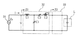
図11は、特許文献1に記載の従来の高周波電力供給システムの構成例を示す図である。この高周波電力供給システムは、高周波電力を出力するための高周波電源装置31と、この高周波電源装置31に例えば同軸ケーブルを介して接続され、高周波電源装置31の入力インピーダンスと負荷インピーダンスとを整合するためのインピーダンス整合器32と、このインピーダンス整合器32に接続された銅板等からなる負荷接続部33と、この負荷接続部33に接続され例えばプラズマ処理装置からなる負荷Lとで構成されている。
FIG. 11 is a diagram illustrating a configuration example of a conventional high-frequency power supply system described in
高周波電源装置31は、負荷Lに対して高周波電力を供給するための装置であり、図示しない電力増幅回路や発振回路等を備え、所定の電力に設定された高周波電力をインピーダンス整合器32に出力する。
The high frequency
インピーダンス整合器32は、その入力端から高周波電源装置31側を見た入力インピーダンスと、その入力端から負荷L側を見た負荷インピーダンスとを整合させるためのものであり、高周波電源装置31の出力を効率よく負荷Lに供給するのに用いられる。
The
負荷Lは、エッチングやCVD等の方法を用いて半導体ウェハや液晶基板等の被加工物を加工するための装置である。より詳細には、負荷Lは、例えばプラズマ処理装置(プラズマチャンバー)とされ、このプラズマ処理装置は、内部に備えた真空容器にプラズマ発生用のガスが導入され、供給された高周波電力を用いて上記ガスを電離させて、プラズマを発生させるものである。発生されたプラズマは、半導体ウェハや液晶基板等の被加工物を加工するために利用される。 The load L is an apparatus for processing a workpiece such as a semiconductor wafer or a liquid crystal substrate using a method such as etching or CVD. More specifically, the load L is, for example, a plasma processing apparatus (plasma chamber). The plasma processing apparatus uses a high frequency power supplied by introducing a gas for generating plasma into a vacuum vessel provided inside. The gas is ionized to generate plasma. The generated plasma is used for processing a workpiece such as a semiconductor wafer or a liquid crystal substrate.
ここで、負荷Lは、高周波電力の出力周波数fと反射係数Г(又はインピーダンス)との関係において、図12に示すように、所定の出力周波数fsにおいて反射係数Гが最小値Гsとなるような特性を有する。また、負荷Lでは、プラズマ処理装置に封入されたガス、プラズマ処理装置内の気圧等の負荷状態によって、図12の一点鎖線で示すように、時間の経過にともなって反射係数Гが最小値Гs′となる出力周波数fが出力周波数fs′に変化するというように、その特性が頻繁に変化する。 Here, in the relationship between the output frequency f of the high frequency power and the reflection coefficient Γ (or impedance), the load L is such that the reflection coefficient Γ becomes the minimum value Γs at a predetermined output frequency fs as shown in FIG. Has characteristics. Further, at the load L, the reflection coefficient Γ has a minimum value Γs as time passes, depending on the load state such as the gas sealed in the plasma processing apparatus, the atmospheric pressure in the plasma processing apparatus, etc., as shown by the one-dot chain line in FIG. The characteristic changes frequently, such that the output frequency f at 'changes to the output frequency fs'.
図11に示すインピーダンス整合器32には、インダクタL1,L2及びインピーダンス可変素子としての可変キャパシタC1,C2からなる整合回路と、高周波電圧V、高周波電流I、及び高周波電圧Vと高周波電流Iとの位相差θを検出する検出器(図略)と、可変キャパシタC1,C2のキャパシタンスの値を調整するための制御回路(図略)とが設けられている。可変キャパシタC1,C2は、制御回路から出力される制御信号に基づいてモータ(図略)が駆動し、そのキャパシタンスの値が調整可能となっている。
The
制御回路は、検出器によって検出された高周波電圧V、高周波電流I、及びそれらの位相差θを入力し、それらに基づいてインピーダンス整合器32の入力インピーダンスZ1を演算する。制御回路は、入力インピーダンスZ1と、可変キャパシタC1,C2のインピーダンスZc1,Zc2とに基づいて、インピーダンス整合器32の出力端子から負荷L側を見た負荷回路側インピーダンスZ2を演算する。
The control circuit inputs the high-frequency voltage V, the high-frequency current I, and the phase difference θ detected by the detector, and calculates the input impedance Z1 of the impedance matching
そして、制御回路は、算出された負荷回路側インピーダンスZ2に基づいて、入力インピーダンスZ1が高周波電源装置31側の出力インピーダンスZs(例えば50Ω)に一致するように、可変キャパシタC1,C2の調整位置を変化させ、高周波電源装置31と負荷Lとのインピーダンスを整合させるようになっている。
Based on the calculated load circuit side impedance Z2, the control circuit sets the adjustment positions of the variable capacitors C1 and C2 so that the input impedance Z1 matches the output impedance Zs (for example, 50Ω) on the high frequency
しかしながら、このインピーダンス整合器32は、インピーダンスを整合させる処理に例えば約1秒程度の時間を要する。そのため、反射係数の最小値及びその出力周波数が時間の経過にともなって即座に変化する負荷Lには、上記インピーダンス整合器32は不向きである。また、インピーダンス整合器32では、上記したように、インピーダンス整合を行う際に、可変キャパシタC1,C2のキャパシタンスを調整するためのモータを駆動させるのであるが、インピーダンス整合器32は、このようにモータ等の駆動部品を用いているため、メンテナンス性に優れたものといえず、また故障しやすいといった欠点を有する。さらに、インピーダンス整合器32は、装置自体のコストが高いといった欠点もある。
However, the impedance matching
そこで、本願出願人は、上記のような可変キャパシタC1,C2を備えたインピーダンス整合器32を用いずに、高周波電源装置31から出力される高周波電力の出力周波数を可変させることにより、負荷Lに対して適切な高周波電力を供給することができるのではと考え、本願発明に至った。
Therefore, the applicant of the present application changes the output frequency of the high-frequency power output from the high-frequency
本願発明は、上記した事情のもとで考え出されたものであって、反射係数が最小となる高周波電力の出力周波数を迅速に求め、その出力周波数に調整して高周波電力を出力する高周波電源装置を提供することを、その課題とする。 The present invention has been conceived under the circumstances described above, and quickly obtains the output frequency of high-frequency power that minimizes the reflection coefficient, and adjusts the output frequency to output the high-frequency power. An object is to provide an apparatus.
上記の課題を解決するため、本願発明では、次の技術的手段を講じている。 In order to solve the above problems, the present invention takes the following technical means.
本願発明によって提供される高周波電源装置は、高周波電力を発生し、供給される高周波電力の反射特性が時間的に変動する負荷にその高周波電力を供給する周波数可変の電力発生手段と、前記負荷に入射される高周波電力と前記負荷から反射される高周波電力を検出する電力検出手段と、前記電力検出手段で検出された前記負荷への入射電力と前記負荷からの反射電力とに基づいて反射係数を算出する反射係数算出手段と、予め設定された周波数範囲内で周波数を変化させて前記電力発生手段から前記高周波電力を発生させ、前記反射係数算出手段で算出される反射係数が最小となる周波数を求める周波数探索手段と、前記周波数探索手段で求められた周波数の高周波電力を前記電力発生手段で発生させ、前記負荷に供給する電力供給制御手段と、を備えた高周波電源装置であって、前記周波数探索手段は、予め設定された周波数の可変範囲内の所定の初期周波数を含み当該可変範囲よりも狭い第1の周波数探索範囲を設定する第1の探索範囲設定手段と、前記設定された第1の周波数探索範囲内に2つの周波数を第1の対周波数として設定する第1の周波数設定手段と、前記電力発生手段から前記第1の対周波数として設定された2つの周波数の高周波電力を発生させたときに、前記反射係数算出手段で算出された前記第1の対周波数の2つの周波数のそれぞれに対応する反射係数のうち小さい方の反射係数を選択する第1の反射係数選択手段と、前記小さい方の反射係数に対応する周波数を選択する第1の周波数選択手段と、前記第1の周波数選択手段で選択された反射係数の小さい周波数を含むように、且つ前記第1の周波数探索範囲の周波数幅よりも周波数幅が狭い第2の周波数探索範囲を設定する第2の探索範囲設定手段と、前記第2の探索範囲設定手段で設定された前記第2の周波数探索範囲内に2つの周波数を第2の対周波数として設定する第2の周波数設定手段と、前記電力発生手段から前記第2の対周波数として設定された2つの周波数の高周波電力を発生させたときに、前記反射係数算出手段で算出された前記第2の対周波数の2つの周波数のそれぞれに対応する反射係数のうち小さい方の反射係数を選択する第2の反射係数選択手段と、前記小さい方の反射係数に対応する周波数を選択する第2の周波数選択手段と、前記第2の反射係数選択手段で選択された反射係数が前記第1の反射係数選択手段で選択された反射係数より小さいか否かを判定する判定手段と、前記判定手段で前記第2の反射係数選択手段で選択した反射係数が前記第1の反射係数選択手段で選択した反射係数以上と判定されると、前記第1の反射係数選択手段で選択した反射係数を最小反射係数に設定するとともに、前記第1の周波数選択手段で選択した周波数を前記反射係数が最小となる周波数として出力する探索周波数出力手段と、前記判定手段で前記第2の反射係数選択手段で選択した反射係数が前記第1の反射係数選択手段で選択した反射係数未満と判定されている間は、前記第2の周波数選択手段で選択した周波数を含むように前記第1の周波数探索範囲を設定して、前記第1の周波数設定手段乃至前記判定手段による周波数探索処理を繰り返す探索処理制御手段と、を備えたことを特徴としている(請求項1)。 High-frequency power supply device provided by the present invention, a high-frequency power generated, the power generating means of the supplied high-frequency power reflection characteristics temporally you supplies the high-frequency power to varying load frequency variable, the Power detection means for detecting high-frequency power incident on the load and high-frequency power reflected from the load, reflection based on the incident power on the load detected by the power detection means and the reflected power from the load A reflection coefficient calculation means for calculating a coefficient, and the high frequency power is generated from the power generation means by changing the frequency within a preset frequency range, and the reflection coefficient calculated by the reflection coefficient calculation means is minimized. Frequency search means for obtaining a frequency, and power supply control for generating high-frequency power of the frequency obtained by the frequency search means by the power generation means and supplying the load to the load A high-frequency power supply device including a stage, wherein the frequency search means sets a narrow first frequency search range than the variable range including a predetermined initial frequency within the variable range of a preset frequency A first search range setting means; a first frequency setting means for setting two frequencies within the set first frequency search range as a first pair of frequencies; and When high frequency power of two frequencies set as the counter frequency is generated, the smaller one of the reflection coefficients corresponding to the two frequencies of the first counter frequency calculated by the reflection coefficient calculating means First reflection coefficient selection means for selecting a reflection coefficient, first frequency selection means for selecting a frequency corresponding to the smaller reflection coefficient, and the reflection coefficient selected by the first frequency selection means Second search range setting means for setting a second frequency search range that includes a small frequency and having a frequency width narrower than the frequency width of the first frequency search range; and the second search range setting means A second frequency setting means for setting two frequencies as a second pair frequency within the second frequency search range set in step (2), and two frequencies set as the second pair frequency from the power generation means. A second reflection coefficient that selects a smaller one of the reflection coefficients corresponding to each of the two frequencies of the second pair of frequencies calculated by the reflection coefficient calculation means when high-frequency power of a frequency is generated; Reflection coefficient selection means, second frequency selection means for selecting a frequency corresponding to the smaller reflection coefficient, and the reflection coefficient selected by the second reflection coefficient selection means are the first reflection coefficient selection means. A determination means for determining whether the reflection coefficient is smaller than the reflection coefficient selected at the stage, and the reflection coefficient selected by the second reflection coefficient selection means by the determination means is the reflection coefficient selected by the first reflection coefficient selection means If determined as above, the reflection coefficient selected by the first reflection coefficient selection unit is set to the minimum reflection coefficient, and the frequency selected by the first frequency selection unit is set as the frequency at which the reflection coefficient is minimized. While the search frequency output means for outputting and the reflection coefficient selected by the second reflection coefficient selection means by the determination means are determined to be less than the reflection coefficient selected by the first reflection coefficient selection means, the first A search process in which the first frequency search range is set so as to include the frequency selected by the second frequency selection means, and the frequency search process by the first frequency setting means through the determination means is repeated. It is characterized by comprising a control unit, a (claim 1).
この構成によれば、供給される高周波電力の出力周波数に応じて反射特性が時間の経過にともなって変動する負荷に対して、予め設定された周波数範囲内において反射係数が最小となる出力周波数を求める。まず、周波数範囲内の所定の初期周波数を含み当該可変範囲よりも狭い第1の周波数探索範囲を設定し、その第1の周波数探索範囲内に2つの周波数を第1の対周波数として設定して両周波数における反射係数を求める。続いて、第1の対周波数のうち、反射係数の小さい周波数を選択し、その周波数を含み且つ第1の周波数探索範囲の周波数幅よりも周波数幅が狭い第2の周波数探索範囲を設定し、その第2の周波数探索範囲内に2つの周波数を第2の対周波数として設定して両周波数における反射係数を求める。続いて、第2の対周波数のうち、反射係数の小さいほうの周波数を選択し、その周波数の反射係数が第1の対周波数に対して求めた反射係数のうち、小さいほうの反射係数より小さいか否かを判定し、小さいほうの反射係数以上であれば、当該小さいほうの反射係数を有する周波数を反射係数が最小となる周波数として出力し、小さいほうの反射係数未満であれば、周波数探索範囲を狭くして上記の第2の周波数探索範囲の設定処理から判定処理を最小反射係数が得られるまで繰り返す。そして、求められた出力周波数を有する高周波電力を負荷に対して供給する。そのため、例えば出力周波数をスキャンして各出力周波数の反射係数を随時計測し、計測した反射係数の中から最小の反射係数を選択し、その反射係数に係る出力周波数を求める方法に比べ、短時間で反射係数が最小となる出力周波数を求めることができる。しかも、負荷が反射係数の最小値が時間の経過にともなって変動する場合、その変動に迅速に追従することができる。 According to this configuration, for a load whose reflection characteristics fluctuate with time according to the output frequency of the supplied high-frequency power, the output frequency that minimizes the reflection coefficient within a preset frequency range is obtained. Ask. First, a first frequency search range including a predetermined initial frequency within the frequency range and narrower than the variable range is set, and two frequencies are set as first pair frequencies within the first frequency search range. Find the reflection coefficient at both frequencies. Subsequently, a frequency having a small reflection coefficient is selected from the first pair of frequencies, and a second frequency search range that includes the frequency and is narrower than the frequency width of the first frequency search range is set. Two frequencies are set as the second pair frequency within the second frequency search range, and the reflection coefficients at both frequencies are obtained. Subsequently, of the second pair frequencies, the frequency having the smaller reflection coefficient is selected, and the reflection coefficient of the frequency is smaller than the smaller reflection coefficient of the reflection coefficients obtained for the first pair frequency. If the reflection coefficient is smaller than the smaller reflection coefficient, the frequency having the smaller reflection coefficient is output as the frequency that minimizes the reflection coefficient, and if it is less than the smaller reflection coefficient, the frequency search is performed. The range is narrowed and the determination process from the setting process of the second frequency search range is repeated until the minimum reflection coefficient is obtained. And the high frequency electric power which has the calculated | required output frequency is supplied with respect to a load. Therefore, for example, scanning the output frequency and measuring the reflection coefficient of each output frequency as needed, selecting the minimum reflection coefficient from the measured reflection coefficients, and calculating the output frequency related to the reflection coefficient in a shorter time. Thus, the output frequency that minimizes the reflection coefficient can be obtained. In addition, when the minimum value of the reflection coefficient fluctuates with time, the load can quickly follow the fluctuation.
また、上記高周波電源装置において、前記第1及び第2の周波数設定手段は、所定の比率を用いて前記2つの周波数を設定するとよい(請求項2)。 In the above high-frequency power source, the first and second frequency setting means may set the two frequencies using Jo Tokoro ratio (Claim 2).
また、上記高周波電源装置において、前記周波数探索手段によって求められた最小反射係数に基づいて変動基準幅を決定する変動基準幅決定手段と、前記電力供給制御手段によって高周波電力の周波数が制御されているときに、所定の周期で前記反射係数算出手段により反射係数を算出させる反射係数監視手段と、前記反射係数算出手段によって算出される反射係数が前記変動基準幅を外れたか否かを判別する判別手段と、前記判別手段により反射係数が前記変動基準幅を外れていなければ、前記電力発生手段により発生される高周波電力の周波数を前記周波数探索手段によって求められた反射係数が最小となる周波数に保持し、前記判別手段により反射係数が前記変動基準幅を外れたと判別されると、前記周波数探索手段により反射係数が最小となる周波数を再探索させる周波数探索制御手段と、を更に備えるとよい(請求項3)。 In the high frequency power supply apparatus, the frequency of the high frequency power is controlled by the fluctuation reference width determining means for determining the fluctuation reference width based on the minimum reflection coefficient obtained by the frequency searching means and the power supply control means. Sometimes, the reflection coefficient monitoring means for calculating the reflection coefficient by the reflection coefficient calculation means at a predetermined period, and the determination means for determining whether or not the reflection coefficient calculated by the reflection coefficient calculation means is out of the fluctuation reference width. If the reflection coefficient does not deviate from the fluctuation reference width by the determination means, the frequency of the high frequency power generated by the power generation means is held at a frequency at which the reflection coefficient obtained by the frequency search means is minimized. When the discrimination means determines that the reflection coefficient has deviated from the fluctuation reference width, the reflection coefficient is determined by the frequency search means. A frequency search control means for re-search the frequency to be small, may further comprise a (claim 3).
また、上記高周波電源装置において、前記変動基準幅は、前記周波数探索手段によって求められた最小反射係数の値に応じて予め設定されており、かつ当該反射係数の値が小さいほどその基準幅が大きく設定されているとよい(請求項4)。 In the high-frequency power supply device, the fluctuation reference width is set in advance according to the value of the minimum reflection coefficient obtained by the frequency search means, and the reference width increases as the reflection coefficient value decreases. It may be set (Claim 4 ).
本願発明のその他の特徴および利点は、添付図面を参照して以下に行う詳細な説明によって、より明らかとなろう。 Other features and advantages of the present invention will become more apparent from the detailed description given below with reference to the accompanying drawings.
以下、本願発明の好ましい実施の形態を、添付図面を参照して具体的に説明する。 Hereinafter, preferred embodiments of the present invention will be specifically described with reference to the accompanying drawings.
図1は、本願発明に係る高周波電源装置が適用される高周波電力供給システムの一例を示す図である。この高周波電力供給システムは、半導体ウェハや液晶基板等の被加工物に対して高周波電力を供給して、例えばプラズマエッチングといった加工処理を行うものである。この高周波電力供給システムは、高周波電源装置1、伝送線路2、インピーダンス整合器3、負荷接続部4及び負荷Lで構成されている。
FIG. 1 is a diagram showing an example of a high-frequency power supply system to which a high-frequency power supply device according to the present invention is applied. This high-frequency power supply system supplies high-frequency power to a workpiece such as a semiconductor wafer or a liquid crystal substrate, and performs processing such as plasma etching. The high-frequency power supply system includes a high-frequency
高周波電源装置1には、例えば同軸ケーブルからなる伝送線路2を介してインピーダンス整合器3が接続され、インピーダンス整合器3には、例えば電磁波が漏れないように遮蔽された銅板からなる負荷接続部4が接続され、負荷接続部4には、負荷Lが接続されている。
An
高周波電源装置1は、負荷Lに対して例えば数百kHz以上の出力周波数を有する高周波電力を供給するための装置である。高周波電源装置1については後述する。
The high frequency
インピーダンス整合器3は、高周波電源装置1と負荷Lとのインピーダンスを整合させるものであり、図示しないが、インピーダンス素子であるキャパシタやインダクタ等を備えている。より具体的には、例えば高周波電源装置1の出力端から高周波電源装置1側を見たインピーダンス(出力インピーダンス)が例えば50Ωに設計され、高周波電源装置1が、特性インピーダンス50Ωの伝送線路2でインピーダンス整合器3の入力端に接続されているとすると、インピーダンス整合器3は、当該インピーダンス整合器3の入力端から負荷L側を見たインピーダンスを50Ωに整合する。
The
負荷Lは、半導体ウェハや液晶基板等の被加工物をエッチングやCVD等の方法を用いて加工するためのプラズマ処理装置(プラズマチャンバー)である。プラズマ処理装置では、被加工物の加工目的に応じて各種の加工プロセスが実行される。例えば、被加工物に対してエッチングを行う場合には、そのエッチングに応じたガス種類、ガス圧力、高周波電力の供給電力値、及び高周波電力の供給時間等が適切に設定された加工プロセスが行われる。加工プロセスでは、被加工物が配置される容器(図略)内に例えば窒素やアルゴン等のプラズマ放電用ガスが導入され、高周波電力の供給が開始されると、容器内に設けられた2つの端子の間に所定の電圧が印加され、その印加された電圧によってプラズマ放電用ガスが放電されて非プラズマ状態からプラズマ状態になる。そして、プラズマ状態になったガスを用いて被加工物が加工される。 The load L is a plasma processing apparatus (plasma chamber) for processing a workpiece such as a semiconductor wafer or a liquid crystal substrate using a method such as etching or CVD. In the plasma processing apparatus, various processing processes are executed according to the processing purpose of the workpiece. For example, when etching a workpiece, a processing process in which the gas type, gas pressure, high-frequency power supply power value, high-frequency power supply time, and the like according to the etching are appropriately set is performed. Is called. In the processing process, when a plasma discharge gas such as nitrogen or argon is introduced into a container (not shown) in which a workpiece is placed and the supply of high-frequency power is started, the two provided in the container A predetermined voltage is applied between the terminals, and the plasma discharge gas is discharged by the applied voltage to change from the non-plasma state to the plasma state. Then, the workpiece is processed using the plasma gas.
本実施形態における高周波電源装置1は、高周波電力を負荷Lに対して供給するものであって、出力周波数を調整して高周波電力を出力することのできる周波数可変装置である。すなわち、負荷Lでは、図12に示したように、高周波電力の出力周波数に応じて反射係数の値が時間の経過にともなって変動するのであるが、この高周波電源装置1は、変動する反射係数の値を定期的に取得するようにし、反射係数が最小となるような高周波電力の出力周波数に調整して当該高周波電力を出力することにより、負荷Lに対して適切なエネルギーを供給するようにしている。
The high frequency
高周波電源装置1は、図1に示すように、出力電力設定部11と、制御部12と、メモリ13と、発振部14と、増幅部15と、パワー検出部16と、反射係数算出部17とを備えている。
As shown in FIG. 1, the high-frequency
出力電力設定部11は、例えばユーザ等によって負荷Lに出力すべき高周波電力を設定するためのものであり、図1では省略しているが、高周波電力の出力値を設定するための出力電力設定スイッチ、高周波電力の供給の開始を指示する出力開始スイッチ、及び後述する探索処理において用いられる基準出力周波数f0を設定する周波数設定スイッチ等が備えられた操作部が設けられている。出力電力設定部11において設定された高周波電力の出力値や基準出力周波数f0のデータは、制御部12に出力される。
The output
制御部12は、本高周波電源装置1の制御中枢となるものであり、反射係数算出部17において算出された反射係数に基づいて、反射係数が最小となる出力周波数を探索し、取得する機能を有する。また、反射係数が出力周波数にともなって変動した場合、反射係数が最小となる出力周波数を追従し、取得する機能を有するとともに、上記探索機能及び追従機能によって取得された出力周波数に基づいて高周波電力の出力周波数を調整する機能を有する。
The
すなわち、上記したように負荷Lでは、時間の経過にともないその負荷状態、つまり反
射係数が最小となる出力周波数が変動するのであるが、高周波電力の出力周波数が一定のまま負荷Lに供給すると、反射係数が増大していって、適当なエネルギーが負荷Lに対して供給されなくなることがあり、負荷Lにおいてプラズマが発生しなくなることがある。したがって、制御部12では、常時、反射係数が最小となる出力周波数を追従して取得し、当該出力周波数に調整しながら負荷Lに対して高周波電力を供給することにより、負荷Lにおいてプラズマを適切に発生させるようにするとともに、その状態を維持させるようにしている。
That is, as described above, in the load L, the load state with time, that is, the output frequency at which the reflection coefficient is minimized fluctuates, but when the output frequency of the high frequency power is supplied to the load L while being constant, The reflection coefficient is increased, and appropriate energy may not be supplied to the load L, and plasma may not be generated in the load L. Therefore, the
制御部12には、メモリ13が接続されており、メモリ13には、反射係数が最小となる高周波電力の出力周波数を探索、追従し、高周波電力をその出力周波数に調整するための制御プログラムが記憶されている。また、メモリ13には、反射係数算出部17において計測された反射係数の値や探索処理において取得された反射係数の値等が変数データとして記憶される。また、メモリ13には、探索処理において取得された反射係数の最小値に対応して、追従処理を行うか否かの判別基準となる変動基準幅が予め記憶されている。この変動基準幅については後述する。
A
発振部14は、制御部12からの制御信号によってその発振出力の出力周波数が制御されるものである。すなわち、上記した探索処理及び追従処理によって出力周波数を調整する必要があると判別されたときには、発振部14は、制御部12から出力周波数を調整する内容の制御信号を入力し、その制御信号に基づいて発振出力の出力周波数を変換し、発振出力信号として増幅部15に出力する。
The
増幅部15は、発振部14からの発振出力信号を増幅して高周波電力を出力するものである。増幅部15において増幅された発振出力信号は、パワー検出部16を介してインピーダンス整合器3に出力される。
The amplifying
パワー検出部16は、増幅部15から出力される高周波電力を検出するものであり、例えば、方向性結合器によって構成されている。パワー検出部16は、増幅部15から負荷L側に進行する高周波(以下、進行波という。)と負荷L側から反射してくる高周波(以下、反射波という。)とを分離して、それらの電力値をそれぞれ検出するものである。パワー検出部16において検出された進行波及び反射波の電力値は、反射係数算出部17に出力される。
The
反射係数算出部17は、パワー検出部16から入力される進行波の値及び反射波の電力値に基づいて、反射係数Гを算出するものである。反射係数Гは、例えば進行波の電力Pf及び反射波の電力Prとの割合Pr/Pfを演算することにより求められる。この反射係数Гの値は、制御部12からのタイマー割り込み信号に応じて制御部12に対して定期的に出力される。
The reflection
本高周波電源装置1においては、図2に示すような方法を用いて、反射係数が最小となる出力周波数fmを求めている。すなわち、所定の周波数範囲fa〜fbに対して周波数範囲fa〜fbより小さい探索範囲dを設定する。探索範囲d内で2点の出力周波数fa′,fb′を選び、各出力周波数fa′,fb′における反射係数の小さい方の出力周波数fb′を選択する。次いで、選択された出力周波数fb′を中心にして新たに探索範囲d′を設定し、探索範囲d′内で2点の出力周波数fa″,fb″を選び、反射係数の小さい方の出力周波数fb″を選択する。そして、上記のように探索範囲を変更しながら反射係数が最小となる出力周波数fmを求めるようにしている。
In the high frequency
そして、反射係数が最小となる出力周波数fmを求めた後、反射特性が変化して出力周波数fmにおける反射係数が所定の閾値ГLを超えた場合、反射係数が最小となる出力周波数fm′を取得するために、上記した方法を繰り返す追従する処理を行っている。 Then, after obtaining the output frequency fm that minimizes the reflection coefficient, when the reflection characteristic changes and the reflection coefficient at the output frequency fm exceeds a predetermined threshold Γ L , the output frequency fm ′ that minimizes the reflection coefficient is obtained. In order to acquire, the processing which repeats the above-mentioned method is performed.
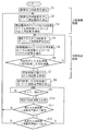
上記方法に係る制御動作について図3に示すフローチャートを参照して説明する。この制御動作においては、まず、反射係数が最小となる高周波電力の出力周波数を探索し取得する探索処理が行われ、その後、反射係数の値が変動すると、その反射係数の値を追従して反射係数が最小となる出力周波数を取得する追従処理が行われ、高周波電力の出力を、取得した出力周波数に調整しながら負荷Lに対し供給する。 The control operation according to the above method will be described with reference to the flowchart shown in FIG. In this control operation, first, a search process for searching for and acquiring the output frequency of the high-frequency power that minimizes the reflection coefficient is performed. After that, when the value of the reflection coefficient fluctuates, the reflection coefficient value is tracked and reflected. A follow-up process for acquiring an output frequency having a minimum coefficient is performed, and the output of high-frequency power is supplied to the load L while adjusting the acquired output frequency.
まず、ユーザの出力電力設定部11を通じた操作によって、所定の周波数範囲fa〜fb(例えば13MHz〜14MHz)に対して、高周波電力の出力レベルや高周波電力の出力周波数の探索処理において基準となる基準出力周波数f0が設定される(S1)。この基準出力周波数f0の値は、負荷Lであるプラズマ処理装置に対する出力周波数として標準的に用いられる、例えば13.56MHzに設定される。なお、基準出力周波数f0の値は、これに限らず、任意の値に設定されてもよい。
First, a reference that is used as a reference in a search process for an output level of high-frequency power or an output frequency of high-frequency power for a predetermined frequency range fa to fb (for example, 13 MHz to 14 MHz) by an operation through the user's output
次いで、反射係数が最小となる大まかな出力周波数を探索する探索処理(以下、「大略探索処理」という。)を行う。すなわち、この大略探索処理においては、図4に示すように、設定された任意の基準出力周波数f0(例えば13.56MHz)を中心として、所定の周波数範囲fa〜fbより狭い探索範囲d(出力周波数f1〜出力周波数f2)が決定される(S2)。 Next, search processing (hereinafter referred to as “substantially search processing”) for searching for a rough output frequency with a minimum reflection coefficient is performed. That is, in this approximate search process, as shown in FIG. 4 , a search range d (output frequency) narrower than a predetermined frequency range fa to fb with a set reference output frequency f0 (for example, 13.56 MHz) as the center. f1 to output frequency f2) are determined (S2).
この場合の探索範囲dは、基準出力周波数f0を中心として例えば±100kHzの範囲とされる。このように、所定の周波数範囲fa〜fbに対して探索範囲dを比較的狭い範囲に設定しているのは、プラズマ処理装置の場合、高周波電力の出力周波数によってはプラズマが消滅してしまう領域(周波数範囲)があり、探索範囲dが、少しでもプラズマが消滅してしまう領域に含まれないようにするためである。 In this case, the search range d is, for example, a range of ± 100 kHz around the reference output frequency f0. Thus, the reason why the search range d is set to a relatively narrow range with respect to the predetermined frequency range fa to fb is that the plasma is extinguished depending on the output frequency of the high frequency power in the case of the plasma processing apparatus. This is because there is (frequency range) and the search range d is not included in the region where the plasma disappears even a little.
次いで、例えば黄金比を用いて探索範囲d内の2つの出力周波数f3,f4が設定され(図5の上図参照)、出力周波数f3,f4における反射係数Г3,Г4が計測される。そして、計測された反射係数Г3,Г4のうちで小さい方の反射係数(図5ではГ4)が選択され、その反射係数における出力周波数(図5ではf4)が取得される(S3)。 Next, for example, using the golden ratio, two output frequencies f3 and f4 within the search range d are set (see the upper diagram of FIG. 5), and reflection coefficients Γ3 and Γ4 at the output frequencies f3 and f4 are measured. Then, the smaller one of the measured reflection coefficients Γ3 and Γ4 (Γ4 in FIG. 5) is selected, and the output frequency (f4 in FIG. 5) at the reflection coefficient is acquired (S3).
具体的には、制御部12では、まず、発振部14に高周波電力を出力周波数f3で出力すべき制御信号が出力される。発振部14では、増幅部15に対して出力周波数f3で出力すべき発振出力信号が出力され、増幅部15から出力周波数f3である高周波電力が負荷Lに対して出力される。パワー検出部16では、出力された高周波電力に基づいて進行波の電力及び反射波の電力が検出され、それらは反射係数算出部17に出力される。反射係数算出部17では、それらの進行波の電力及び反射波の電力に基づいて反射係数Г3が算出され、制御部12に出力される。これにより、制御部12は、出力周波数f3における反射係数Г3を取得する。
More specifically, the
制御部12では、同様にして、発振部14に高周波電力を出力周波数f4で出力すべき制御信号が出力されることにより、出力周波数f4における反射係数Г4が取得される。そして、反射係数Г3,Г4のうち、小さい方の反射係数Г4が選択され、選択された反射係数Г4とそのときの出力周波数f4とは、一旦メモリ13に記憶される。なお、探索範囲d内の2つの出力周波数f3,f4を設定する方法は、黄金比を用いる方法に限るものではない。
Similarly, the
次いで、制御部12では、取得した出力周波数に基づいて反射係数の最小値を探索する探索処理(以下、「局所探索処理」という。)が行われる。この局所探索処理では、図5
に示すように、大略探索処理において取得された出力周波数がf4であったとした場合、出力周波数f4を探索範囲の中心として設定し、出力周波数f4を中心とした所定の探索範囲d′(出力周波数f5〜出力周波数f6)を決定する(S4)。この場合、探索範囲d′は、経験的に習得された値が採用されるが、ステップS2で設定した範囲と同じ範囲(±100kHz)でもよく、ステップS2で設定した範囲に定数を掛け合わせた範囲でもよい。
Next, the
As shown in FIG. 4, when the output frequency acquired in the approximate search process is f4, the output frequency f4 is set as the center of the search range, and a predetermined search range d ′ (output frequency) centered on the output frequency f4 is set. f5 to output frequency f6) are determined (S4). In this case, an experientially learned value is adopted as the search range d ′, but it may be the same range (± 100 kHz) as the range set in step S2, and the range set in step S2 is multiplied by a constant. It may be a range.
探索範囲d′が決定されると、上記探索範囲d′内における例えば黄金比で決定された出力周波数f7,f8において、反射係数の小さい方の出力周波数(図5ではf8)が取得される(S5)。このとき、取得された出力周波数f8の値と、当該出力周波数における反射係数Г8とは、一旦メモリ13に記憶される。
When the search range d ′ is determined, the output frequency with the smaller reflection coefficient (f8 in FIG. 5) is acquired at the output frequencies f7 and f8 determined by, for example, the golden ratio in the search range d ′ (see FIG. 5). S5). At this time, the acquired value of the output frequency f8 and the reflection coefficient Γ8 at the output frequency are temporarily stored in the
次いで、このときの出力周波数f8における反射係数Г8と、前回の探索時に取得した出力周波数f4における反射係数Г4とを比較し、いずれが大きいか否かを判別する(S6)。前回の探索時に取得した反射係数Г4が今回の探索時に取得した反射係数Г8より大きい場合(S6:NO)、ステップS4に戻り、さらに局所探索処理を行う。すなわち、この状態は、図6に示すように、今回取得した反射係数Г8が前回取得した反射係数Г4より小さいときを表しており、つまり反射係数の最小値は、今回取得した反射係数Г8よりさらに小さい場合であり、この場合には、反射係数の最小値を探索するために局所探索処理をさらに行う。なお、このときの局所探索処理では、今回取得した出力周波数f8が基準出力周波数として設定される。 Next, the reflection coefficient Γ8 at the output frequency f8 at this time is compared with the reflection coefficient Γ4 at the output frequency f4 acquired at the previous search to determine which is larger (S6). When the reflection coefficient Γ4 acquired during the previous search is larger than the reflection coefficient Γ8 acquired during the current search (S6: NO), the process returns to step S4 and further performs a local search process. That is, as shown in FIG. 6, this state represents a case where the reflection coefficient Γ8 acquired this time is smaller than the reflection coefficient Γ4 acquired last time, that is, the minimum value of the reflection coefficient is further greater than the reflection coefficient Γ8 acquired this time. In this case, local search processing is further performed to search for the minimum value of the reflection coefficient. In the local search process at this time, the output frequency f8 acquired this time is set as the reference output frequency.
一方、前回の探索時に取得した反射係数Г4が今回の探索時に取得した反射係数Г8より小さい場合、又は反射係数Г4及び反射係数Г8の値が同じ場合(S6:YES)、ステップS7に進む。すなわち、この状態は、図7に示すように、前回取得した反射係数Г4が今回取得した反射係数Г8より小さいか又は同じときを表しており、つまり、前回取得した反射係数Г4が最小値となっている場合である。このようにして、反射係数Г4が探索範囲内における最小値として取得される(S7)。 On the other hand, if the reflection coefficient Γ4 acquired during the previous search is smaller than the reflection coefficient Γ8 acquired during the current search, or if the values of the reflection coefficient Γ4 and the reflection coefficient Γ8 are the same (S6: YES), the process proceeds to step S7. That is, as shown in FIG. 7, this state represents the time when the reflection coefficient Γ4 acquired last time is smaller than or the same as the reflection coefficient Γ8 acquired this time, that is, the reflection coefficient Γ4 acquired last time becomes the minimum value. It is a case. In this way, the reflection coefficient Γ4 is acquired as the minimum value within the search range (S7).
次に、ステップS8では、前回の探索時に取得し、最小値として取得された反射係数Г4に基づいて、その反射係数が変動した場合に、変動する反射係数の値を追従するか否かの判別基準となる変動基準幅を決定する。 Next, in step S8, based on the reflection coefficient Γ4 acquired at the previous search and acquired as the minimum value, it is determined whether or not to follow the value of the changing reflection coefficient when the reflection coefficient changes. Determine the reference fluctuation range.
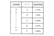
以下では、変動基準幅の決定方法について説明する。図8は、例えばメモリ13に記憶される変動基準幅を示すテーブルである。図8によれば、反射係数は、その値に応じて複数のゾーンに区分けされており、各ゾーンによって変動基準幅が異なるように予め設定されている。また、反射係数の値が大きいゾーンほど、変動基準幅が小さくなるように設定されている。例えば、図9に示すように、最小値として取得した反射係数Г4がAゾーン内にあるとすると、反射係数Г4の変動基準幅は例えば±10%とされる。また、例えば、最小値として取得した反射係数Г4がEゾーン内にあるとすると、反射係数Г4の変動基準幅は例えば±500%とされる。
Hereinafter, a method for determining the fluctuation reference width will be described. FIG. 8 is a table showing the variation reference width stored in the
ここで、Aゾーンにある反射係数Г4が時間の経過にともなって変動し、反射係数の値が±10%の範囲を外れたときに、その反射係数を追従する追従処理が行われるようになっている。また、Eゾーンにある反射係数Г4が時間の経過にともなって変動し、反射係数の値が±500%の範囲を外れたときに、その反射係数を追従する追従処理が行われるようになっている。 Here, when the reflection coefficient Γ4 in the A zone fluctuates with time and the value of the reflection coefficient is out of the range of ± 10%, follow-up processing that follows the reflection coefficient is performed. ing. In addition, when the reflection coefficient Γ4 in the E zone fluctuates with time and the reflection coefficient value is out of the range of ± 500%, a follow-up process for following the reflection coefficient is performed. Yes.
このように、反射係数の大小によって変動基準幅が異なるように設定されているのは、仮に各ゾーンで変動基準幅が同じであって反射係数が小さい場合に変動基準幅が小さく設定されているとすると、追従処理を頻繁に行う必要がある。反射係数が小さい場合には、負荷の状態が比較的安定しているため、そのような状態で追従処理を行ってもあまり意味がないからである。また、逆に、反射係数が大きい場合に変動基準幅が大きく設定されているとすると、追従処理があまり行われなくなる。反射係数が大きい場合には、その変化が激しいため、その変化を適確に捉える必要があるからである。 Thus, the reason why the fluctuation reference width is set to be different depending on the magnitude of the reflection coefficient is that the fluctuation reference width is set to be small when the fluctuation reference width is the same in each zone and the reflection coefficient is small. Then, it is necessary to frequently perform the tracking process. This is because when the reflection coefficient is small, the load state is relatively stable, and it is not meaningful to perform the tracking process in such a state. Conversely, if the fluctuation reference width is set to be large when the reflection coefficient is large, the tracking process is not performed much. This is because when the reflection coefficient is large, the change is so severe that it is necessary to accurately grasp the change.
なお、上記したゾーンの数は、図8に示したテーブルにおける数に限るものではない。また、変動基準幅は、図10に示すように、反射係数の絶対値によって反射係数が大きいほど変動基準幅が小さくなるように区分されていてもよい。 The number of zones described above is not limited to the number in the table shown in FIG. Further, as shown in FIG. 10, the fluctuation reference width may be divided so that the fluctuation reference width becomes smaller as the reflection coefficient is larger according to the absolute value of the reflection coefficient.
図3に戻り、制御部12では、反射係数が定期的に監視され、反射係数が上記変動基準幅を外れるか否かが判別される。すなわち、制御部12では、タイマー割り込み信号が反射係数算出部17に出力され(S9)、タイマー割り込み時に反射係数算出部17で算出された反射係数Гcの値が取り込まれる(S10)。すなわち、取り込まれる反射係数Гcの値は、現時点において計測された反射係数の値である。そして、取り込んだ反射係数ГcとステップS8において設定した反射係数の変動基準幅の上限値Гuとが比較され、取り込んだ反射係数Гcの値が変動基準幅の上限値Гuより小さいか否かを判別する(S11)。
Returning to FIG. 3 , the
取り込んだ反射係数Гcが変動基準幅の上限値Гuより小さい場合(S11:YES)、取り込んだ反射係数ГcとステップS8において設定した反射係数の変動基準幅の下限値Гdとが比較され、取り込んだ反射係数Гcの値が変動基準幅の下限値Гdより大きいか否かが判別される(S12)。取り込んだ反射係数Гcが変動基準幅の下限値Гdより大きい場合(S12:YES)、ステップS9に戻り、再度、定期的に反射係数が上記変動基準幅を外れるか否かが判別される。すなわち、この状態は、反射係数の変動が小さくて、変動基準幅を外れない場合を示している。 When the captured reflection coefficient Γc is smaller than the upper limit value Γu of the variation reference width (S11: YES), the captured reflection coefficient Γc is compared with the lower limit value Γd of the variation reference width of the reflection coefficient set in step S8 and captured. It is determined whether or not the value of the reflection coefficient Γc is larger than the lower limit value Γd of the fluctuation reference width (S12). When the captured reflection coefficient Γc is larger than the lower limit value Γd of the fluctuation reference width (S12: YES), the process returns to step S9, and it is determined again whether or not the reflection coefficient regularly deviates from the fluctuation reference width. That is, this state shows a case where the variation of the reflection coefficient is small and the variation reference width cannot be deviated.
一方、取り込んだ反射係数Гcの値が変動基準幅の上限値Гuを越える場合(S11:NO)、すなわち、反射係数が大きくなる方向に変動した場合、ステップS2の大略探索処理に戻り、取り込んだ反射係数Гcにおける出力周波数を基準出力周波数f0として探索範囲を決定し、再度、反射係数が最小となる出力周波数を取得する探索処理が行われる。 On the other hand, when the value of the captured reflection coefficient Γc exceeds the upper limit value Γu of the fluctuation reference width (S11: NO), that is, when the reflection coefficient fluctuates in the increasing direction, the process returns to the approximate search process in step S2 and is captured. A search process is performed in which the search range is determined with the output frequency at the reflection coefficient Γc as the reference output frequency f0, and the output frequency at which the reflection coefficient is minimized is obtained again.
また、取り込んだ反射係数Гcの値が変動基準幅の上限値Гuを越えないが(S11:YES)、取り込んだ反射係数Гcの値が変動基準幅の下限値Гdを下回った場合(S12:NO)、すなわち、反射係数が小さくなる方向に変動した場合も、ステップS2の大略探索処理に戻る。 Further, when the value of the captured reflection coefficient Γc does not exceed the upper limit value Γu of the fluctuation reference width (S11: YES), but the value of the captured reflection coefficient Γc falls below the lower limit value Γd of the fluctuation reference width (S12: NO) ), That is, when the reflection coefficient fluctuates in the direction of decreasing, the process returns to the approximate search process in step S2.
以降、上記した大略探索処理及び局所探索処理を繰り返し、時間の経過にともない変化する反射係数が最小となる出力周波数を追従していく。反射係数Гcの値が変動基準幅を外れた場合に行われる大略探索処理及び局所探索処理は、変化する反射係数が最小となる出力周波数を追従する追従処理として機能する。これにより、常時、反射係数が最小となる出力周波数を取得することができ、プラズマが発生している負荷Lに対して適切な高周波電力を供給することができる。 Thereafter, the above-described approximate search process and local search process are repeated, and the output frequency that minimizes the reflection coefficient that changes with the passage of time is followed. The approximate search process and local search process performed when the value of the reflection coefficient Γc deviates from the fluctuation reference width functions as a follow-up process that follows the output frequency at which the changing reflection coefficient is minimum. As a result, an output frequency with a minimum reflection coefficient can be obtained at all times, and appropriate high-frequency power can be supplied to the load L where plasma is generated.
反射係数が最小となる出力周波数を探索する方法としては、例えば所定の周波数領域において出力周波数を所定の間隔でスキャンさせ、スキャンされた出力周波数における反射係数をそれぞれ計測し、計測された反射係数の中から最小の反射係数と、その最小の反射係数における出力周波数とを取得する方法もある。 As a method of searching for an output frequency that minimizes the reflection coefficient, for example, the output frequency is scanned at a predetermined interval in a predetermined frequency region, the reflection coefficient at the scanned output frequency is measured, and the measured reflection coefficient is measured. There is also a method of obtaining the minimum reflection coefficient from the medium and the output frequency at the minimum reflection coefficient.
しかしながら、この方法によれば、所定の間隔ごとにスキャンさせて反射係数を所定の間隔ごとに取得するので、時間を要するという欠点があり、変動する反射係数に対して迅速に処理していくことが困難である。ところが、本実施形態に係る探索方法によれば、所定の探索範囲を設定してその探索範囲内において最小となる反射係数を探索していくので、変動する反射係数の最小値を迅速に取得することができる。 However, according to this method, scanning is performed at predetermined intervals and the reflection coefficient is obtained at predetermined intervals. Therefore, there is a disadvantage that it takes time , and processing is performed quickly for the changing reflection coefficient. Is difficult. However, according to the search method according to the present embodiment, since a predetermined search range is set and the reflection coefficient that is the smallest in the search range is searched, the minimum value of the changing reflection coefficient is quickly acquired. be able to.
もちろん、この発明の範囲は上述した実施の形態に限定されるものではない。 Of course, the scope of the present invention is not limited to the embodiment described above.
1 高周波電源装置
3 インピーダンス整合器
11 出力電力設定部
12 制御部
13 メモリ
14 発振部
15 増幅部
16 パワー検出部
17 反射係数算出部
d 探索範囲
f0 基準出力周波数
L 負荷
DESCRIPTION OF
Claims (4)
前記負荷に入射される高周波電力と前記負荷から反射される高周波電力を検出する電力検出手段と、
前記電力検出手段で検出された前記負荷への入射電力と前記負荷からの反射電力とに基づいて反射係数を算出する反射係数算出手段と、
予め設定された周波数範囲内で周波数を変化させて前記電力発生手段から前記高周波電力を発生させ、前記反射係数算出手段で算出される反射係数が最小となる周波数を求める周波数探索手段と、
前記周波数探索手段で求められた周波数の高周波電力を前記電力発生手段で発生させ、前記負荷に供給する電力供給制御手段と、
を備えた高周波電源装置であって、
前記周波数探索手段は、
予め設定された周波数の可変範囲内の所定の初期周波数を含み当該可変範囲よりも狭い第1の周波数探索範囲を設定する第1の探索範囲設定手段と、
前記設定された第1の周波数探索範囲内に2つの周波数を第1の対周波数として設定する第1の周波数設定手段と、
前記電力発生手段から前記第1の対周波数として設定された2つの周波数の高周波電力を発生させたときに、前記反射係数算出手段で算出された前記第1の対周波数の2つの周波数のそれぞれに対応する反射係数のうち小さい方の反射係数を選択する第1の反射係数選択手段と、
前記小さい方の反射係数に対応する周波数を選択する第1の周波数選択手段と、
前記第1の周波数選択手段で選択された反射係数の小さい周波数を含むように、且つ前記第1の周波数探索範囲の周波数幅よりも周波数幅が狭い第2の周波数探索範囲を設定する第2の探索範囲設定手段と、
前記第2の探索範囲設定手段で設定された前記第2の周波数探索範囲内に2つの周波数を第2の対周波数として設定する第2の周波数設定手段と、
前記電力発生手段から前記第2の対周波数として設定された2つの周波数の高周波電力を発生させたときに、前記反射係数算出手段で算出された前記第2の対周波数の2つの周波数のそれぞれに対応する反射係数のうち小さい方の反射係数を選択する第2の反射係数選択手段と、
前記小さい方の反射係数に対応する周波数を選択する第2の周波数選択手段と、
前記第2の反射係数選択手段で選択された反射係数が前記第1の反射係数選択手段で選択された反射係数より小さいか否かを判定する判定手段と、
前記判定手段で前記第2の反射係数選択手段で選択した反射係数が前記第1の反射係数選択手段で選択した反射係数以上と判定されると、前記第1の反射係数選択手段で選択した反射係数を最小反射係数に設定するとともに、前記第1の周波数選択手段で選択した周波数を前記反射係数が最小となる周波数として出力する探索周波数出力手段と、
前記判定手段で前記第2の反射係数選択手段で選択した反射係数が前記第1の反射係数選択手段で選択した反射係数未満と判定されている間は、前記第2の周波数選択手段で選択した周波数を含むように前記第1の周波数探索範囲を設定して、前記第1の周波数設定手段乃至前記判定手段による周波数探索処理を繰り返す探索処理制御手段と、
を備えたことを特徴とする、高周波電源装置。 Generating a high-frequency power, and the power generating means of the reflection characteristic of the high frequency power that to supply the high frequency power to a load that fluctuates temporally frequency variable supplied,
Power detection means for detecting high frequency power incident on the load and high frequency power reflected from the load;
Reflection coefficient calculation means for calculating a reflection coefficient based on the incident power to the load detected by the power detection means and the reflected power from the load;
A frequency searching means for changing the frequency within a preset frequency range to generate the high-frequency power from the power generating means, and obtaining a frequency at which the reflection coefficient calculated by the reflection coefficient calculating means is minimized;
Power supply control means for generating high-frequency power of the frequency obtained by the frequency search means by the power generation means and supplying the load to the load;
A high frequency power supply device comprising:
The frequency search means includes
First search range setting means for setting a first frequency search range including a predetermined initial frequency within a variable range of a preset frequency and narrower than the variable range;
First frequency setting means for setting two frequencies as a first counter frequency within the set first frequency search range;
When high-frequency power having two frequencies set as the first counter frequency is generated from the power generating means, each of the two frequencies of the first counter frequency calculated by the reflection coefficient calculating means is used. First reflection coefficient selection means for selecting a smaller reflection coefficient among the corresponding reflection coefficients;
First frequency selecting means for selecting a frequency corresponding to the smaller reflection coefficient;
A second frequency search range is set to include a frequency having a small reflection coefficient selected by the first frequency selection means and having a frequency width narrower than the frequency width of the first frequency search range. Search range setting means;
Second frequency setting means for setting two frequencies as a second counter frequency within the second frequency search range set by the second search range setting means;
When high frequency power of two frequencies set as the second counter frequency is generated from the power generating means, each of the two frequencies of the second counter frequency calculated by the reflection coefficient calculating means is used. Second reflection coefficient selection means for selecting a smaller reflection coefficient among the corresponding reflection coefficients;
Second frequency selection means for selecting a frequency corresponding to the smaller reflection coefficient;
Determination means for determining whether the reflection coefficient selected by the second reflection coefficient selection means is smaller than the reflection coefficient selected by the first reflection coefficient selection means;
When the determination means determines that the reflection coefficient selected by the second reflection coefficient selection means is greater than or equal to the reflection coefficient selected by the first reflection coefficient selection means, the reflection selected by the first reflection coefficient selection means Search frequency output means for setting a coefficient to a minimum reflection coefficient and outputting the frequency selected by the first frequency selection means as a frequency at which the reflection coefficient is minimum;
While the reflection coefficient selected by the second reflection coefficient selection means by the determination means is determined to be less than the reflection coefficient selected by the first reflection coefficient selection means, the selection is made by the second frequency selection means. Search processing control means for setting the first frequency search range to include a frequency and repeating frequency search processing by the first frequency setting means to the determination means;
A high frequency power supply device comprising:
前記電力供給制御手段によって高周波電力の周波数が制御されているときに、所定の周期で前記反射係数算出手段により反射係数を算出させる反射係数監視手段と、
前記反射係数算出手段によって算出される反射係数が前記変動基準幅を外れたか否かを判別する判別手段と、
前記判別手段により反射係数が前記変動基準幅を外れていなければ、前記電力発生手段により発生される高周波電力の周波数を前記周波数探索手段によって求められた反射係数が最小となる周波数に保持し、前記判別手段により反射係数が前記変動基準幅を外れたと判別されると、前記周波数探索手段により反射係数が最小となる周波数を再探索させる周波数探索制御手段と、
を更に備えた、請求項1又は2に記載の高周波電源装置。 A fluctuation reference width determining means for determining a fluctuation reference width based on a minimum reflection coefficient obtained by the frequency search means;
A reflection coefficient monitoring means for calculating a reflection coefficient by the reflection coefficient calculation means at a predetermined period when the frequency of the high frequency power is controlled by the power supply control means;
Discriminating means for discriminating whether or not the reflection coefficient calculated by the reflection coefficient calculating means is out of the fluctuation reference width;
If the reflection coefficient does not deviate from the fluctuation reference width by the determination means, the frequency of the high frequency power generated by the power generation means is held at a frequency at which the reflection coefficient obtained by the frequency search means is minimized, When it is determined by the determining means that the reflection coefficient has deviated from the fluctuation reference width, the frequency search control means for re-searching for the frequency at which the reflection coefficient is minimized by the frequency searching means;
Further comprising a high frequency power supply device according to claim 1 or 2.
前記周波数探索手段によって求められた最小反射係数の値に応じて予め設定されており、かつ当該反射係数の値が小さいほどその基準幅が大きく設定されている、請求項3に記載の高周波電源装置。 The fluctuation reference width is
The high-frequency power supply device according to claim 3 , wherein the high-frequency power supply device is preset according to the value of the minimum reflection coefficient obtained by the frequency search means, and the reference width is set larger as the value of the reflection coefficient is smaller. .
Priority Applications (2)
| Application Number | Priority Date | Filing Date | Title |
|---|---|---|---|
| JP2005101593A JP4739793B2 (en) | 2005-03-31 | 2005-03-31 | High frequency power supply |
| US11/391,115 US7292047B2 (en) | 2005-03-31 | 2006-03-28 | High-frequency power source |
Applications Claiming Priority (1)
| Application Number | Priority Date | Filing Date | Title |
|---|---|---|---|
| JP2005101593A JP4739793B2 (en) | 2005-03-31 | 2005-03-31 | High frequency power supply |
Publications (3)
| Publication Number | Publication Date |
|---|---|
| JP2006286254A JP2006286254A (en) | 2006-10-19 |
| JP2006286254A5 JP2006286254A5 (en) | 2008-04-03 |
| JP4739793B2 true JP4739793B2 (en) | 2011-08-03 |
Family
ID=37069597
Family Applications (1)
| Application Number | Title | Priority Date | Filing Date |
|---|---|---|---|
| JP2005101593A Expired - Fee Related JP4739793B2 (en) | 2005-03-31 | 2005-03-31 | High frequency power supply |
Country Status (2)
| Country | Link |
|---|---|
| US (1) | US7292047B2 (en) |
| JP (1) | JP4739793B2 (en) |
Families Citing this family (37)
| Publication number | Priority date | Publication date | Assignee | Title |
|---|---|---|---|---|
| JP4799947B2 (en) * | 2005-02-25 | 2011-10-26 | 株式会社ダイヘン | High frequency power supply device and control method of high frequency power supply |
| JP5089032B2 (en) * | 2005-10-12 | 2012-12-05 | 長野日本無線株式会社 | Method for controlling automatic matching unit for plasma processing apparatus |
| US8203859B2 (en) | 2006-12-29 | 2012-06-19 | Daihen Corporation | High frequency device with variable frequency and variable load impedance matching |
| US8040068B2 (en) * | 2009-02-05 | 2011-10-18 | Mks Instruments, Inc. | Radio frequency power control system |
| KR101679580B1 (en) | 2009-10-16 | 2016-11-29 | 삼성전자주식회사 | Wireless Power Transmission Device, Wireless Power Transmission Controlling Device and Wireless Power Transmission Method |
| JP5430437B2 (en) * | 2010-02-17 | 2014-02-26 | 三菱電機株式会社 | Ignition device and ignition method |
| KR20110110525A (en) | 2010-04-01 | 2011-10-07 | 삼성전자주식회사 | Wireless power transmission apparatus and wireless power transmission mehod |
| WO2012094416A1 (en) * | 2011-01-04 | 2012-07-12 | Advanced Energy Industries, Inc. | System level power delivery to a plasma processing load |
| DE102011076404B4 (en) | 2011-05-24 | 2014-06-26 | TRUMPF Hüttinger GmbH + Co. KG | A method of impedance matching the output impedance of a high frequency power supply arrangement to the impedance of a plasma load and high frequency power supply arrangement |
| US8576013B2 (en) * | 2011-12-29 | 2013-11-05 | Mks Instruments, Inc. | Power distortion-based servo control systems for frequency tuning RF power sources |
| US9171699B2 (en) * | 2012-02-22 | 2015-10-27 | Lam Research Corporation | Impedance-based adjustment of power and frequency |
| US8773019B2 (en) | 2012-02-23 | 2014-07-08 | Mks Instruments, Inc. | Feedback control and coherency of multiple power supplies in radio frequency power delivery systems for pulsed mode schemes in thin film processing |
| US8952765B2 (en) * | 2012-03-23 | 2015-02-10 | Mks Instruments, Inc. | System and methods of bimodal automatic power and frequency tuning of RF generators |
| US9210790B2 (en) * | 2012-08-28 | 2015-12-08 | Advanced Energy Industries, Inc. | Systems and methods for calibrating a switched mode ion energy distribution system |
| JP6084417B2 (en) * | 2012-09-28 | 2017-02-22 | 株式会社ダイヘン | Impedance adjustment device |
| US9294100B2 (en) * | 2012-12-04 | 2016-03-22 | Advanced Energy Industries, Inc. | Frequency tuning system and method for finding a global optimum |
| JP6282806B2 (en) * | 2012-12-28 | 2018-02-21 | 株式会社ダイヘン | High frequency power supply |
| US9155182B2 (en) * | 2013-01-11 | 2015-10-06 | Lam Research Corporation | Tuning a parameter associated with plasma impedance |
| JP6099995B2 (en) * | 2013-01-24 | 2017-03-22 | 東京エレクトロン株式会社 | Test equipment |
| DE102014209469A1 (en) * | 2014-05-19 | 2015-11-19 | TRUMPF Hüttinger GmbH + Co. KG | Control arrangement, control system and high-frequency power generation device |
| JP2016054041A (en) * | 2014-09-03 | 2016-04-14 | 株式会社島津製作所 | High frequency power supply device |
| JP6479562B2 (en) * | 2015-05-07 | 2019-03-06 | 東京エレクトロン株式会社 | Method of generating processing condition of plasma processing apparatus and plasma processing apparatus |
| US10622197B2 (en) | 2015-07-21 | 2020-04-14 | Tokyo Electron Limited | Plasma processing apparatus and plasma processing method |
| US9748076B1 (en) * | 2016-04-20 | 2017-08-29 | Advanced Energy Industries, Inc. | Apparatus for frequency tuning in a RF generator |
| JP6157036B1 (en) | 2016-07-08 | 2017-07-05 | 株式会社京三製作所 | High frequency power supply device and control method of high frequency power supply device |
| US10784807B2 (en) * | 2017-05-11 | 2020-09-22 | Siemens Aktiengesellschaft | Methods and systems for controlling an electrical machine |
| WO2019010312A1 (en) | 2017-07-07 | 2019-01-10 | Advanced Energy Industries, Inc. | Inter-period control system for plasma power delivery system and method of operating the same |
| US11615943B2 (en) | 2017-07-07 | 2023-03-28 | Advanced Energy Industries, Inc. | Inter-period control for passive power distribution of multiple electrode inductive plasma source |
| US11651939B2 (en) | 2017-07-07 | 2023-05-16 | Advanced Energy Industries, Inc. | Inter-period control system for plasma power delivery system and method of operating same |
| KR20200100642A (en) | 2017-11-17 | 2020-08-26 | 에이이에스 글로벌 홀딩스 피티이 리미티드 | Spatial and temporal control of ion bias voltage for plasma processing |
| JP2020159949A (en) * | 2019-03-27 | 2020-10-01 | 東京エレクトロン株式会社 | High frequency supply device and method for supplying high frequency power |
| JP7348101B2 (en) * | 2020-02-18 | 2023-09-20 | 株式会社京三製作所 | Control method of high frequency power supply device and high frequency power supply device |
| JP2021180070A (en) * | 2020-05-11 | 2021-11-18 | 東京エレクトロン株式会社 | Plasma processing device and microwave control method |
| TW202336804A (en) * | 2021-11-19 | 2023-09-16 | 日商東京威力科創股份有限公司 | Plasma treatment device, power supply system, control method, program, and storage medium |
| US11942309B2 (en) | 2022-01-26 | 2024-03-26 | Advanced Energy Industries, Inc. | Bias supply with resonant switching |
| US11670487B1 (en) | 2022-01-26 | 2023-06-06 | Advanced Energy Industries, Inc. | Bias supply control and data processing |
| JP2023183584A (en) * | 2022-06-16 | 2023-12-28 | 東京エレクトロン株式会社 | High-frequency power supply, plasma processing device, and matching method |
Family Cites Families (6)
| Publication number | Priority date | Publication date | Assignee | Title |
|---|---|---|---|---|
| JP3183914B2 (en) | 1991-08-29 | 2001-07-09 | 株式会社ダイヘン | Automatic impedance matching device |
| US6020794A (en) * | 1998-02-09 | 2000-02-01 | Eni Technologies, Inc. | Ratiometric autotuning algorithm for RF plasma generator |
| US6946847B2 (en) * | 2002-02-08 | 2005-09-20 | Daihen Corporation | Impedance matching device provided with reactance-impedance table |
| JP3977114B2 (en) * | 2002-03-25 | 2007-09-19 | 株式会社ルネサステクノロジ | Plasma processing equipment |
| JP3822857B2 (en) * | 2002-10-29 | 2006-09-20 | 長野日本無線株式会社 | Plasma generation method, plasma apparatus, and semiconductor manufacturing apparatus |
| US6781317B1 (en) * | 2003-02-24 | 2004-08-24 | Applied Science And Technology, Inc. | Methods and apparatus for calibration and metrology for an integrated RF generator system |
-
2005
- 2005-03-31 JP JP2005101593A patent/JP4739793B2/en not_active Expired - Fee Related
-
2006
- 2006-03-28 US US11/391,115 patent/US7292047B2/en not_active Expired - Fee Related
Also Published As
| Publication number | Publication date |
|---|---|
| JP2006286254A (en) | 2006-10-19 |
| US20060220656A1 (en) | 2006-10-05 |
| US7292047B2 (en) | 2007-11-06 |
Similar Documents
| Publication | Publication Date | Title |
|---|---|---|
| JP4739793B2 (en) | High frequency power supply | |
| JP2006286254A5 (en) | ||
| JP6400272B2 (en) | Power and frequency adjustment based on impedance | |
| JP4879548B2 (en) | High frequency power supply | |
| EP2377243B1 (en) | Signal generating system | |
| JP6424024B2 (en) | Plasma processing apparatus and plasma processing method | |
| US10475624B2 (en) | High-frequency power supply device, and control method for high-frequency power supply device | |
| JP2007103102A5 (en) | ||
| CN111868875A (en) | Frequency tuning for unmatched plasma sources | |
| US10896810B2 (en) | RF generating apparatus and plasma treatment apparatus | |
| KR101128768B1 (en) | High frequency power supply | |
| US10879045B2 (en) | Plasma processing apparatus | |
| JPH09266098A (en) | Plasma condition detecting device and method, and etching terminating point detecting device and method | |
| JP4593948B2 (en) | High frequency power supply | |
| JP4493896B2 (en) | Plasma processing apparatus and plasma processing stop method | |
| JPH09266097A (en) | Plasma processing method and device | |
| JP2005109183A (en) | Method for controlling output power of high-frequency power supply and high-frequency power unit | |
| US11810759B2 (en) | RF generator | |
| KR20180080632A (en) | Apparatus of supplying power for generating plasma | |
| JP2006288009A (en) | High-frequency power supply unit | |
| JP2006288009A5 (en) | ||
| JP2000049146A (en) | High-frequency plasma treatment method and apparatus for detecting termination of process | |
| KR20040084079A (en) | Apparatus and method for matching an radio frequency | |
| JP4763247B2 (en) | High frequency power supply output power control method and high frequency power supply apparatus |
Legal Events
| Date | Code | Title | Description |
|---|---|---|---|
| A521 | Written amendment |
Free format text: JAPANESE INTERMEDIATE CODE: A523 Effective date: 20080219 |
|
| A621 | Written request for application examination |
Free format text: JAPANESE INTERMEDIATE CODE: A621 Effective date: 20080219 |
|
| A977 | Report on retrieval |
Free format text: JAPANESE INTERMEDIATE CODE: A971007 Effective date: 20100823 |
|
| A131 | Notification of reasons for refusal |
Free format text: JAPANESE INTERMEDIATE CODE: A131 Effective date: 20100831 |
|
| A521 | Written amendment |
Free format text: JAPANESE INTERMEDIATE CODE: A523 Effective date: 20101028 |
|
| TRDD | Decision of grant or rejection written | ||
| A01 | Written decision to grant a patent or to grant a registration (utility model) |
Free format text: JAPANESE INTERMEDIATE CODE: A01 Effective date: 20110426 |
|
| A01 | Written decision to grant a patent or to grant a registration (utility model) |
Free format text: JAPANESE INTERMEDIATE CODE: A01 |
|
| A61 | First payment of annual fees (during grant procedure) |
Free format text: JAPANESE INTERMEDIATE CODE: A61 Effective date: 20110428 |
|
| R150 | Certificate of patent or registration of utility model |
Ref document number: 4739793 Country of ref document: JP Free format text: JAPANESE INTERMEDIATE CODE: R150 Free format text: JAPANESE INTERMEDIATE CODE: R150 |
|
| FPAY | Renewal fee payment (event date is renewal date of database) |
Free format text: PAYMENT UNTIL: 20140513 Year of fee payment: 3 |
|
| R250 | Receipt of annual fees |
Free format text: JAPANESE INTERMEDIATE CODE: R250 |
|
| R250 | Receipt of annual fees |
Free format text: JAPANESE INTERMEDIATE CODE: R250 |
|
| R250 | Receipt of annual fees |
Free format text: JAPANESE INTERMEDIATE CODE: R250 |
|
| LAPS | Cancellation because of no payment of annual fees |