JP2006288009A - High-frequency power supply unit - Google Patents
High-frequency power supply unit Download PDFInfo
- Publication number
- JP2006288009A JP2006288009A JP2005101594A JP2005101594A JP2006288009A JP 2006288009 A JP2006288009 A JP 2006288009A JP 2005101594 A JP2005101594 A JP 2005101594A JP 2005101594 A JP2005101594 A JP 2005101594A JP 2006288009 A JP2006288009 A JP 2006288009A
- Authority
- JP
- Japan
- Prior art keywords
- reflection coefficient
- load
- value
- frequency power
- arc
- Prior art date
- Legal status (The legal status is an assumption and is not a legal conclusion. Google has not performed a legal analysis and makes no representation as to the accuracy of the status listed.)
- Withdrawn
Links
Images


Abstract
Description
本願発明は、例えば半導体ウェハプロセスにおいて、プラズマエッチングを行うプラズマ処理装置等といった負荷に高周波電力を供給する高周波電源装置に関するものである。 The present invention relates to a high frequency power supply apparatus that supplies high frequency power to a load such as a plasma processing apparatus that performs plasma etching in a semiconductor wafer process, for example.
従来、高周波電力を負荷に対して供給するシステムとしては、図9に示すように、例えば高周波電力を出力するための高周波電源装置31と、この高周波電源装置31に伝送ケーブル32を介して接続され、高周波電源装置31の入力インピーダンスと負荷インピーダンスとを整合するためのインピーダンス整合器33と、このインピーダンス整合器33に負荷接続部34を介して接続され、例えばプラズマ処理装置からなる負荷Lとで構成されている(例えば、特許文献1参照)。
Conventionally, as a system for supplying high frequency power to a load, as shown in FIG. 9, for example, a high frequency
高周波電源装置31は、負荷Lに対して高周波電力を供給するための装置であり、例えば図示しない電力増幅回路や発振回路等を備え、所定の電力に設定された高周波電力をインピーダンス整合器33を介して負荷Lに出力する。
The high-frequency
負荷Lは、エッチングやCVD等の方法を用いて半導体ウェハや液晶基板等の被加工物を加工するための装置である。より詳細には、負荷Lは、例えばプラズマ処理装置(プラズマチャンバー)とされ、このプラズマ処理装置は、内部に備えた真空容器にプラズマ発生用のガスが導入され、供給された高周波電力を用いて上記ガスを電離させて、プラズマを発生させるものである。発生されたプラズマは、半導体ウェハや液晶基板等の被工作物を加工するために利用される。 The load L is an apparatus for processing a workpiece such as a semiconductor wafer or a liquid crystal substrate using a method such as etching or CVD. More specifically, the load L is, for example, a plasma processing apparatus (plasma chamber). The plasma processing apparatus uses a high frequency power supplied by introducing a gas for generating plasma into a vacuum vessel provided inside. The gas is ionized to generate plasma. The generated plasma is used to process a workpiece such as a semiconductor wafer or a liquid crystal substrate.
ここで、負荷Lとしてのプラズマ処理装置では、内部に大電流が流れてインピーダンスが急激に変化するとアークが発生することがある。アークが発生すると、プラズマ処理装置が破損してしまうことがあるので、高周波電源装置31では、アークの発生を迅速に検出し、負荷Lに対して高周波電力の供給を停止させる必要がある。
Here, in the plasma processing apparatus as the load L, an arc may be generated when a large current flows inside and the impedance changes abruptly. When the arc is generated, the plasma processing apparatus may be damaged. Therefore, the high frequency
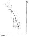
アークの発生を検出する方法としては、所定時間内における反射係数の変化度合いを監視し、その変化の大小に基づいてアークの発生を検出する方法がある。すなわち、図10に示すように、ある時点t11において反射係数Г0が算出されると、その反射係数Г0に基づいて基準下限値Гdと基準上限値Гuとで上下の幅が規定される判定基準幅Wが設定され、所定時間Tの間において反射係数の値が基準下限値Гdを越え、かつ基準上限値Гuを越えた場合に、アークが発生したと検出している(図10において一点鎖線Aがアークが発生したと検出される場合の反射係数の変化を示す。)。 As a method of detecting the occurrence of an arc, there is a method of monitoring the degree of change of the reflection coefficient within a predetermined time and detecting the occurrence of the arc based on the magnitude of the change. That is, as shown in FIG. 10, when the reflection coefficient Γ0 is calculated at a certain point in time t11, the determination reference width in which the upper and lower widths are defined by the reference lower limit value Γd and the reference upper limit value Γu based on the reflection coefficient Γ0. When W is set and the value of the reflection coefficient exceeds the reference lower limit value Γd and exceeds the reference upper limit value Γu during a predetermined time T, it is detected that an arc has occurred (the dashed line A in FIG. 10). Shows the change in the reflection coefficient when it is detected that an arc has occurred.)
従来のアークを検出する方法では、図10に示したように、判定基準幅Wが反射係数の大小にかかわらず一定とされている。すなわち、判定基準幅Wの基準下限値Гd及び基準上限値Гuは、反射係数Гの値に応じてそれぞれ設定されるものの、基準下限値Гdと基準上限値Гuとの差、すなわち判定基準幅Wは、反射係数Гの値にかかわらず一定とされている。 In the conventional method for detecting an arc, as shown in FIG. 10, the determination reference width W is constant regardless of the magnitude of the reflection coefficient. That is, the reference lower limit value Γd and the reference upper limit value Γu of the determination reference width W are set according to the value of the reflection coefficient Γ, respectively, but the difference between the reference lower limit value Γd and the reference upper limit value Γu, that is, the determination reference width W Is constant regardless of the value of the reflection coefficient Γ.
例えば反射係数が比較的大きい場合には、負荷Lでは不安定な状態になっているため、少しのインピーダンスの変化、すなわち少しの反射係数の変化によってアークが発生することがある。しかしながら、従来のアークを検出する方法では、反射係数の大小にかかわらず判定基準幅は一定とされているため、反射係数が比較的大きい場合、そのときの反射係数の変化量は小さいのであるがアークが発生しているときに、それを検出することができないことがあるといった問題点がある。 For example, when the reflection coefficient is relatively large, since the load L is unstable, an arc may be generated due to a slight impedance change, that is, a slight reflection coefficient change. However, in the conventional method for detecting an arc, the determination reference width is constant regardless of the magnitude of the reflection coefficient. Therefore, when the reflection coefficient is relatively large, the amount of change in the reflection coefficient at that time is small. There is a problem that when an arc is generated, it may not be detected.
本願発明は、上記した事情のもとで考え出されたものであって、負荷において発生するアークの発生を検出するとき、その検出精度を向上させることができる高周波電源装置を提供することを、その課題とする。 The present invention has been conceived under the circumstances described above, and provides a high-frequency power supply device that can improve the detection accuracy when detecting the occurrence of an arc generated in a load. Let that be the issue.
上記の課題を解決するため、本願発明では、次の技術的手段を講じている。 In order to solve the above problems, the present invention takes the following technical means.
本願発明によって提供される高周波電源装置は、負荷に対して高周波電力を供給する電力供給手段と、前記負荷に入射される高周波電力と前記負荷から反射される高周波電力を検出する電力検出手段と、前記電力検出手段で検出された前記負荷への入射電力と前記負荷からの反射電力とに基づいて反射係数を算出する反射係数算出手段と、前記反射係数算出手段によって算出された反射係数の値が所定時間内に予め定める基準幅以上変化したか否かを判別する判別手段と、前記判別手段による判別結果に基づいて、前記負荷におけるアークの発生を検出するアーク検出手段と、を備える高周波電源装置であって、前記反射係数算出手段によって算出された反射係数の値が、前記判別手段によって所定時間内に基準幅以上変化したか否かが判別されるとき、当該反射係数の値に応じて前記基準幅を可変する基準幅変更手段を備えたことを特徴としている(請求項1)。 The high frequency power supply device provided by the present invention includes a power supply means for supplying high frequency power to a load, a high frequency power incident on the load, and a power detection means for detecting high frequency power reflected from the load, Reflection coefficient calculation means for calculating a reflection coefficient based on incident power to the load detected by the power detection means and reflected power from the load, and a value of the reflection coefficient calculated by the reflection coefficient calculation means. A high frequency power supply apparatus comprising: a determination unit that determines whether or not a predetermined reference width has changed within a predetermined time; and an arc detection unit that detects an occurrence of an arc in the load based on a determination result by the determination unit. And determining whether or not the value of the reflection coefficient calculated by the reflection coefficient calculation means has changed by more than a reference width within a predetermined time by the determination means. When it is characterized by having a reference width changing means for varying the reference range in accordance with the value of the reflection coefficient (claim 1).
この構成によれば、反射係数算出手段によって算出された反射係数の値が、判別手段によって所定時間内に基準幅以上変化したか否かが判別されるとき、当該反射係数の値に応じて基準幅が可変される。そのため、例えば反射係数の値が大きいほど基準幅が小さくなるように設定されるとすれば、反射係数が比較的大きいときにおける反射係数の変化が小さくても基準幅を超えればアークが発生したものと検出することができる。すなわち、反射係数が比較的大きい状態では、負荷は不安定な状態にあり、そのような状態のときにインピーダンス(反射係数)が急激に変化すればその変化度合いが小さくてもアークが発生することがある。このため、反射係数が比較的大きいほど基準幅を小さく設定しておけば、アークが発生しているような反射係数の小さい変化でもそれを適格に捉えることができる。したがって、反射係数の値の大小にかかわらず基準幅が一定であった従来の構成に比べ、より精度よくアークの発生を検出することができる。 According to this configuration, when it is determined whether or not the value of the reflection coefficient calculated by the reflection coefficient calculation unit has changed by more than the reference width within a predetermined time by the determination unit, a reference is made according to the value of the reflection coefficient. The width is variable. Therefore, for example, if the reference width is set to be smaller as the value of the reflection coefficient is larger, an arc is generated if the reference width is exceeded even if the change in the reflection coefficient is relatively small when the reflection coefficient is relatively large. Can be detected. That is, when the reflection coefficient is relatively large, the load is in an unstable state, and if the impedance (reflection coefficient) changes suddenly in such a state, an arc is generated even if the degree of change is small. There is. For this reason, if the reference width is set to be smaller as the reflection coefficient is relatively large, even a small change in the reflection coefficient such as an arc can be properly captured. Therefore, it is possible to detect the occurrence of the arc with higher accuracy than the conventional configuration in which the reference width is constant regardless of the value of the reflection coefficient.
また、上記高周波電源装置において、前記アーク検出手段によってアークの発生が検出されたとき、前記電力供給手段による前記負荷に対する高周波電力の供給を停止する供給停止手段がさらに備えられるとよい(請求項2)。 The high-frequency power supply apparatus may further include supply stop means for stopping supply of high-frequency power to the load by the power supply means when the occurrence of an arc is detected by the arc detection means. ).
また、上記高周波電源装置において、前記基準幅は、前記反射係数算出手段によって算出された反射係数の値に応じた値が予め設定されており、かつ当該反射係数の値が大きいほど前記基準幅が小さくなるように選択されて設定されるとよい(請求項3)。 In the high-frequency power supply device, the reference width is set in advance according to the value of the reflection coefficient calculated by the reflection coefficient calculation means, and the reference width increases as the value of the reflection coefficient increases. It may be selected and set so as to decrease (claim 3).
また、上記高周波電源装置において、前記基準幅は、第1閾値と、その第1閾値より値が大きい第2閾値とによってその幅が規定されており、前記アーク検出手段は、前記反射係数算出手段によって算出された反射係数の値が所定時間内に前記第1閾値を越え、かつ前記第2閾値を越えたとき、前記負荷においてアークが発生したと検出するとよい(請求項4)。 Further, in the high frequency power supply device, the reference width is defined by a first threshold value and a second threshold value that is larger than the first threshold value, and the arc detecting means is the reflection coefficient calculating means. When the value of the reflection coefficient calculated by (1) exceeds the first threshold value and exceeds the second threshold value within a predetermined time, it may be detected that an arc has occurred in the load.
本願発明のその他の特徴および利点は、添付図面を参照して以下に行う詳細な説明によって、より明らかとなろう。 Other features and advantages of the present invention will become more apparent from the detailed description given below with reference to the accompanying drawings.
以下、本願発明の好ましい実施の形態を、添付図面を参照して具体的に説明する。 Hereinafter, preferred embodiments of the present invention will be specifically described with reference to the accompanying drawings.
図1は、本願発明に係る高周波電源装置が適用される高周波電力供給システムの一例を示す図である。この高周波電力供給システムは、半導体ウェハや液晶基板等の被加工物に対して高周波電力を供給して、例えばプラズマエッチングといった加工処理を行うものである。この高周波電力供給システムは、高周波電源装置1、伝送線路2、インピーダンス整合器3、負荷接続部4及び負荷Lで構成されている。
FIG. 1 is a diagram showing an example of a high-frequency power supply system to which a high-frequency power supply device according to the present invention is applied. This high-frequency power supply system supplies high-frequency power to a workpiece such as a semiconductor wafer or a liquid crystal substrate, and performs processing such as plasma etching. The high-frequency power supply system includes a high-frequency
高周波電源装置1には、例えば同軸ケーブルからなる伝送線路2を介してインピーダンス整合器3が接続され、インピーダンス整合器3には、例えば電磁波が漏れないように遮蔽された銅板からなる負荷接続部4が接続され、負荷接続部4には、負荷Lが接続されている。
An impedance matching device 3 is connected to the high frequency
高周波電源装置1は、負荷Lに対して例えば数百kHz以上の出力周波数を有する高周波電力を供給するための装置である。高周波電源装置1については後述する。
The high frequency
インピーダンス整合器3は、高周波電源装置1と負荷Lとのインピーダンスを整合させるものであり、図示しないが、インピーダンス素子であるキャパシタやインダクタ等を備えている。より具体的には、例えば高周波電源装置1の出力端から高周波電源装置1側を見たインピーダンス(出力インピーダンス)が例えば50Ωに設計され、高周波電源装置1が、特性インピーダンス50Ωの伝送線路2でインピーダンス整合器3の入力端に接続されているとすると、インピーダンス整合器3は、当該インピーダンス整合器3の入力端から負荷L側を見たインピーダンスを50Ωに整合する。
The impedance matching unit 3 is for matching the impedance between the high-frequency
負荷Lは、半導体ウェハや液晶基板等の被加工物をエッチングやCVD等の方法を用いて加工するためのプラズマ処理装置(プラズマチャンバー)である。プラズマ処理装置では、被加工物の加工目的に応じて各種の加工プロセスが実行される。例えば、被加工物に対してエッチングを行う場合には、そのエッチングに応じたガス種類、ガス圧力、高周波電力の供給電力値、及び高周波電力の供給時間等が適切に設定された加工プロセスが行われる。 The load L is a plasma processing apparatus (plasma chamber) for processing a workpiece such as a semiconductor wafer or a liquid crystal substrate using a method such as etching or CVD. In the plasma processing apparatus, various processing processes are executed according to the processing purpose of the workpiece. For example, when etching a workpiece, a processing process in which the gas type, gas pressure, high-frequency power supply power value, high-frequency power supply time, and the like according to the etching are appropriately set is performed. Is called.
加工プロセスでは、被加工物が配置される容器(図略)内に例えば窒素やアルゴン等のプラズマ放電用ガスが導入される。そして、高周波電力の供給が開始されると、容器内に設けられた2つの端子の間に所定の電圧が印加され、その印加された電圧によってプラズマ放電用ガスが放電されて非プラズマ状態からプラズマ状態になり、プラズマ状態になったガスを用いて被加工物が加工されるようになっている。 In the machining process, a plasma discharge gas such as nitrogen or argon is introduced into a container (not shown) in which a workpiece is placed. When the supply of high frequency power is started, a predetermined voltage is applied between the two terminals provided in the container, and the plasma discharge gas is discharged by the applied voltage, so that the plasma is discharged from the non-plasma state. Thus, the workpiece is processed using the gas in a plasma state.
本実施形態における高周波電源装置1は、高周波電力を負荷Lに対して供給するものであって、出力周波数を調整して高周波電力を出力することのできる周波数可変装置である。また、高周波電源装置1は、変動する反射係数の値を算出してその反射係数の変化に基づいて負荷Lに発生するアークを検出する機能と、アークを検出した場合に負荷Lに対する高周波電力の供給を停止する機能とを有するものである。
The high frequency
すなわち、負荷Lにおいてアークが発生するということは、負荷Lにおいて、過電圧が発生したり過電流が流れたりして、インピーダンスが急激に変化している状態となっている場合である。このアークが発生すると、負荷Lであるプラズマ処理装置が破損することがあるため、高周波電源装置1では、プラズマ処理装置が破損する前にアークを事前に検出して、負荷Lに対して高周波電力の供給を停止するようにしている。
That is, an arc is generated in the load L is a case where the load L is in a state where the impedance is rapidly changed due to an overvoltage or an overcurrent flowing. When this arc occurs, the plasma processing apparatus that is the load L may be damaged. Therefore, the high frequency
高周波電源装置1は、図1に示すように、出力電力設定部11と、制御部12と、メモリ13と、発振部14と、増幅部15と、パワー検出部16と、反射係数算出部17、基準幅設定部18と、アーク検出部19とを備えている。
As shown in FIG. 1, the high-frequency
出力電力設定部11は、例えばユーザ等によって負荷Lに出力すべき高周波電力を設定するためのものであり、図1では省略しているが、高周波電力の出力値を設定するための出力電力設定スイッチ、及び高周波電力の供給の開始を指示する出力開始スイッチ等が備えられた操作部が設けられている。出力電力設定部11において設定された高周波電力の出力値は、制御部12に出力される。
The output
制御部12は、本高周波電源装置1の制御中枢となるものであり、出力電力設定部11において設定された高周波電力の出力値に基づいて発振部14に制御信号を出力することにより、負荷Lに対して高周波電力を供給させるものである。また、本実施形態に係る制御部12は、アーク検出部19からの検出信号に基づいて発振部14を制御することにより、負荷Lに対する高周波電力の供給を停止させる。
The
制御部12には、メモリ13が接続されており、メモリ13には、高周波電力を負荷Lに供給するための制御プログラムが記憶されている。また、メモリ13には、後述するアークの発生を検出する処理で用いられる判定基準幅のデータ(後述する定数K2,K3等)や判定時間のデータが記憶されている。また、メモリ13には、反射係数算出部17において算出される反射係数の値等が変数データとして記憶される。上記判定基準幅や判定時間については後述する。
A
発振部14は、制御部12からの制御信号によってその発振出力の出力周波数が制御されるものである。高周波電力の出力周波数を調整する必要があるときには、発振部14は、制御部12から出力周波数を調整する内容の制御信号を入力し、その制御信号に基づいて発振出力の出力周波数を変換し、発振出力信号として増幅部15に出力する。
The
増幅部15は、発振部14からの発振出力信号を増幅して高周波電力を出力するものである。増幅部15において増幅された発振出力信号は、パワー検出部16を介してインピーダンス整合器3に出力される。
The amplifying
パワー検出部16は、増幅部15から出力される高周波電力を検出するものであり、例えば、方向性結合器によって構成されている。パワー検出部16は、増幅部14から負荷L側に進行する高周波(以下、進行波という。)と負荷L側から反射してくる高周波(以下、反射波という。)とを分離して、それらの電力値をそれぞれ検出するものである。パワー検出部16において検出された進行波の電力値及び反射波の電力値は、反射係数算出部17に出力される。
The
反射係数算出部17は、パワー検出部16から入力される進行波の電力値及び反射波の電力値に基づいて、反射係数Гを算出するものである。反射係数Гは、例えば進行波の電力Pfと反射波の電力Prとの割合Pr/Pfを演算することにより求められる。この反射係数Гの値は、基準幅設定部19に出力される。
The reflection
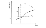
基準幅設定部18は、所定時間(判定時間)内における反射係数の値の変化に基づいてアークが発生したか否かが判別される判別処理において、その判別基準となる判定基準幅を設定するものである。ここで、判定基準幅とは、図2に示すように、反射係数に対して、判定基準下限値Гdと、その値より大きい判定基準上限値Гuとで定められる幅のことである。また、判定時間とは、上記判別処理が行われる時間をいい、図2に示すTで表される時間(例えば100μsec)のことである。すなわち、判定時間Tは、反射係数が算出される時点t1に対して一定時間T0経過後の時刻t2から、判別処理が終了する時刻t3までの時間である。なお、所定時間Tは、任意の値に設定できるようにしてもよい。
The reference
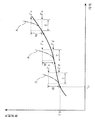
基準幅設定部18では、反射係数算出部17から反射係数が入力されると、その反射係数の値に応じて判定基準幅Wが設定されるのであるが、本実施形態では、その判定基準幅Wが反射係数の値に応じて可変されるようになっている。例えば、図3に示すように、反射係数Г0の値が比較的大きいときには、判定基準幅Wが小さく設定され、反射係数Г0の値が比較的小さいときには、判定基準幅Wが大きく設定される。
In the reference
具体的な判定基準幅Wの設定方法としては、基準下限値Гdは、算出される反射係数Г0に予め定める定数K1(例えば1.01)を掛け合わすことによって設定される。定数K1は、算出される反射係数Г0の値に対して所定値Гaだけ嵩上げして、基準下限値Гdを反射係数Г0の値より少し高めに設定するものである。また、判定基準幅Wは、算出される反射係数Г0に基づいて設定される定数K2に基本値Bが掛け合わされることにより設定される。基本値Bは、判定基準幅Wの最小単位を示すものであり、定数K2は、算出される反射係数Г0の値に応じて予め定められた値である。本実施形態においては、反射係数Г0の値が大きいほど定数K2の値が小さくなるように設定されている。また、基準上限値Гuは、基準下限値Гd+基本値B×定数K2で表され、上式に各数値が代入されることにより基準上限値Гuが設定される。 As a specific method for setting the determination reference width W, the reference lower limit value Γd is set by multiplying the calculated reflection coefficient Γ0 by a predetermined constant K1 (for example, 1.01). The constant K1 is raised by a predetermined value Γa with respect to the calculated value of the reflection coefficient Γ0, and the reference lower limit value Γd is set slightly higher than the value of the reflection coefficient Γ0. Further, the determination reference width W is set by multiplying the constant K2 set based on the calculated reflection coefficient Γ0 by the basic value B. The basic value B indicates the minimum unit of the determination reference width W, and the constant K2 is a value determined in advance according to the calculated value of the reflection coefficient Γ0. In the present embodiment, the value of the constant K2 is set to be smaller as the value of the reflection coefficient Γ0 is larger. The reference upper limit value Γu is represented by the reference lower limit value Γd + basic value B × constant K2, and the reference upper limit value Γu is set by substituting each numerical value into the above equation.
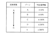
なお、判定基準幅Wの設定方法は、上記方法に限らず、他の方法が用いられてもよい。例えば、反射係数は、図4に示すように、その値に応じて複数のゾーンに区分けされ、各ゾーンによって判定基準幅Wが異なるように予め設定されていてもよい。この場合、反射係数の値が大きいゾーンほど、判定基準幅Wが小さくなるように設定される。例えば、算出された反射係数Г0がAゾーン内にあるとすると、判定基準幅Wは、反射係数Г0の例えば±10%とされる。また、例えば算出された反射係数Г0がEゾーン内にあるとすると、判定基準幅Wは、算出された反射係数Г0の例えば±500%とされる。 Note that the method of setting the determination reference width W is not limited to the above method, and other methods may be used. For example, as shown in FIG. 4, the reflection coefficient may be divided into a plurality of zones according to the value, and may be set in advance so that the determination reference width W varies depending on each zone. In this case, the determination reference width W is set to be smaller as the zone has a larger reflection coefficient value. For example, if the calculated reflection coefficient Γ0 is in the A zone, the determination reference width W is, for example, ± 10% of the reflection coefficient Γ0. For example, if the calculated reflection coefficient Γ0 is in the E zone, the determination reference width W is, for example, ± 500% of the calculated reflection coefficient Γ0.
このように、反射係数の値に応じて判定基準幅Wを可変させれば、アークの発生を高精度で検出することができる。例えば、反射係数の値が大きいほど判定基準幅が小さくなるように設定されているので、反射係数が比較的大きいときにおけるその変化が小さくても判定基準幅を超えればアークが発生したものと検出することができる。 Thus, if the determination reference width W is varied according to the value of the reflection coefficient, the occurrence of an arc can be detected with high accuracy. For example, since the judgment reference width is set to be smaller as the reflection coefficient value is larger, it is detected that an arc has occurred if the judgment reference width is exceeded even if the change when the reflection coefficient is relatively large is small. can do.
すなわち、反射係数が比較的大きい状態では、負荷Lは不安定な状態にあり、そのような状態のときにインピーダンス(反射係数)が急激に変化すればその変化度合いが小さくてもアークが発生することがある。このため、反射係数が比較的大きいほど判定基準幅Wを小さく設定しておけば、アークが発生しているような反射係数が小さい変化でもそれを適格に捉えることができる。したがって、反射係数の値の大小にかかわらず基準幅が一定であった従来の構成に比べ、より精度よくアークの発生を検出することができる。また、アークの発生を高精度に検出できる結果、負荷Lの損傷する可能性を少なくすることができる。 That is, when the reflection coefficient is relatively large, the load L is in an unstable state. If the impedance (reflection coefficient) changes suddenly in such a state, an arc is generated even if the degree of change is small. Sometimes. For this reason, if the determination reference width W is set to be smaller as the reflection coefficient is relatively large, even a small change in the reflection coefficient such that an arc is generated can be properly captured. Therefore, it is possible to detect the occurrence of the arc with higher accuracy than the conventional configuration in which the reference width is constant regardless of the value of the reflection coefficient. Moreover, as a result of detecting the occurrence of the arc with high accuracy, the possibility that the load L is damaged can be reduced.
また、反射係数の値が比較的小さいほど、判定基準幅Wが比較的大きくなるように設定される。反射係数の値が比較的小さい状態では、負荷Lの状態が比較的安定しているため、そのような状態で判定基準幅Wを小さくすると、アークの発生を頻繁に検出することになる。本実施形態では、反射係数の値が比較的小さいときには、判定基準幅Wが大きく設定されるので、アークの発生を頻繁に検出することがなくなり、実用的な装置となる。 The determination reference width W is set to be relatively large as the reflection coefficient value is relatively small. In a state where the value of the reflection coefficient is relatively small, the state of the load L is relatively stable. Therefore, if the determination reference width W is reduced in such a state, occurrence of an arc is frequently detected. In this embodiment, when the value of the reflection coefficient is relatively small, the determination reference width W is set to be large, so that the occurrence of arcs is not frequently detected, and a practical device is obtained.
図1に戻り、アーク検出部19は、反射係数算出部17からの反射係数Гの値に基づいて、負荷Lにおいてアークが発生したか否かを検出するものである。アーク検出部19は、反射係数算出部17からの反射係数Гの値を入力し、反射係数Гの値が所定時間T内に判定基準幅W以上変化した場合、すなわち、反射係数Гの値が所定時間T内に基準下限値Гdを越え、かつ基準上限値Гuを越えたとき、インピーダンスが急激に変化して負荷Lにアークが発生したものとして検出している。アーク検出部19は、アークの発生を検出すると、制御部12に対して検出信号を出力する。
Returning to FIG. 1, the
次に、上記構成における制御動作について図5に示すフローチャートを参照して説明する。 Next, the control operation in the above configuration will be described with reference to the flowchart shown in FIG.
まず、ユーザの出力電力設定部11を通じた操作によって、高周波電力の出力レベルが設定されると、高周波電源装置1から高周波電力が負荷Lに対して供給される(S1)。すなわち、制御部12では、まず、発振部12に高周波電力を所定の出力周波数で出力すべき制御信号が出力される。発振部12では、増幅部15に対して所定の出力周波数で出力すべき発振出力信号が出力され、増幅部15から所定の出力周波数に基づく高周波電力が負荷Lに対して出力される。
First, when the output level of high frequency power is set by the user's operation through the output
パワー検出部16では、増幅部15から出力された高周波電力に基づいて進行波の電力が検出されるとともに、負荷Lで反射された高周波に基づいて反射波の電力が検出され、進行波の電力及び反射波の電力は反射係数算出部17に出力される。反射係数算出部17では、進行波の電力及び反射波の電力に基づいて反射係数Гが算出される(S2)。算出された反射係数Гは、基準幅設定部18に出力される。
The
基準幅設定部18では、反射係数算出部17で算出された反射係数Гに基づいて、判定基準幅Wが設定される。まず、基準下限値Гdが設定される(S3)。具体的には、基準下限値Гdは、算出された反射係数Г0に予めメモリ13に記憶された定数K1(例えば1.01)が乗算されて設定される。
In the reference
次いで、基準上限値Гuが設定される。具体的には、算出された反射係数Г0に応じて定数K2が設定される(S4)。この定数K2は、予めメモリ13に記憶され、反射係数Гに応じて定められた値であり、反射係数Гの値が大きいほど小さく設定されている。判定基準幅Wは、この定数K2に判定基準幅Wの最小単位である基本値Bが掛け合わされて設定される。定数K2は、算出された反射係数Г0の値に応じて予め定められた値である。そして、基準下限値Гd+基本値B×定数K2により基準上限値Гuが設定される(S5)。
Next, a reference upper limit value Γu is set. Specifically, a constant K2 is set according to the calculated reflection coefficient Γ0 (S4). The constant K2 is a value that is stored in advance in the
基準上限値Гuが設定されると、反射係数Гが算出された一定時間T0後、タイマーがスタートされ(S6)、判定処理が開始される。判定時間Tの間は、常時、反射係数算出部17において反射係数Гの値が算出され、その値がアーク検出部19に入力される。そして、アーク検出部19においてアークが発生したか否かの判別処理が行われる。
When the reference upper limit value Γu is set, the timer is started after a certain time T0 when the reflection coefficient Γ is calculated (S6), and the determination process is started. During the determination time T, the value of the reflection coefficient Γ is always calculated by the reflection
具体的には、まず、反射係数Гの値が基準下限値Гdを上回ったか否かが判別される(S7)。反射係数Гの値が基準下限値Гdを上回ったと判別されなかったとき(S7:NO)、判定時間Tが経過したか否かが判別される(S8)。ここで、判定時間Tが経過したと判別されたとき(S8:YES)、この場合は、図6に示すように、反射係数Гの値が判定基準幅W以上の変化をせずに判定時間T経過した場合とされ、アークは発生していないと判定される。その後、処理はステップS2に戻り、反射係数Гの値が新たに算出される。 Specifically, first, it is determined whether or not the value of the reflection coefficient Γ exceeds the reference lower limit value Γd (S7). When it is not determined that the value of the reflection coefficient Γ exceeds the reference lower limit value Γd (S7: NO), it is determined whether the determination time T has elapsed (S8). Here, when it is determined that the determination time T has passed (S8: YES), in this case, as shown in FIG. 6, the determination time without changing the value of the reflection coefficient Γ over the determination reference width W is determined. It is determined that T has elapsed, and it is determined that no arc has occurred. Thereafter, the process returns to step S2, and the value of the reflection coefficient Γ is newly calculated.
また、ステップS7において、反射係数Гの値が基準下限値Гdを上回ったと判別されたとき(S7:YES)、反射係数Гの値が基準上限値Гuを上回ったか否かが判別される(S9)。反射係数Гの値が基準上限値Гuを上回ったと判別されなかったとき(S9:NO)、ステップS8に進み、判定時間Tが経過したか否かが判別される。ここで、判定時間Tが経過したと判別されたとき(S8:YES)、この場合は、図7に示すように、反射係数Гの値は基準下限値Гdを上回ったけれども、判定時間Tが経過したときには基準上限値Гuを上回らなかった場合とされ、この場合もアークは発生していないと判定される。 Further, when it is determined in step S7 that the value of the reflection coefficient Γ exceeds the reference lower limit value Γd (S7: YES), it is determined whether or not the value of the reflection coefficient Γ exceeds the reference upper limit value Γu (S9). ). When it is not determined that the value of the reflection coefficient Γ exceeds the reference upper limit value Γu (S9: NO), the process proceeds to step S8, where it is determined whether the determination time T has elapsed. Here, when it is determined that the determination time T has elapsed (S8: YES), in this case, as shown in FIG. 7, the value of the reflection coefficient Γ exceeds the reference lower limit value Γd. When the time has elapsed, it is determined that the reference upper limit value Γu has not been exceeded. In this case, it is determined that no arc has occurred.
一方、ステップS9において、反射係数Гの値が基準上限値Гuを上回ったと判別されたとき(S9:YES)、すなわち、図8に示すように、反射係数Гの値が判定時間T内で基準下限値Гdを上回り、かつ基準上限値Гuをも上回ったとき、反射係数が急激に変化しているので、アーク検出部19ではアークが発生したと検出される(S10)。
On the other hand, when it is determined in step S9 that the value of the reflection coefficient Γ exceeds the reference upper limit value Γu (S9: YES), that is, as shown in FIG. When the value exceeds the lower limit value Γd and also exceeds the reference upper limit value Γu, since the reflection coefficient changes rapidly, the
アーク検出部19においてアークが発生したと検出されると、その検出信号が制御部12に出力され、制御部12では、高周波電力の供給を停止する処理が行われる(S11)。すなわち、制御部12では、発振部14への制御信号の出力を停止する。これにより、負荷Lに対する高周波電力の供給が停止され、負荷Lにおいて加工プロセスが停止される。
When the
上記の判定処理は、アークの発生を検出しない限り、繰り返し行われるので、負荷Lにおいては安定した状態で加工プロセスを行うことができる。 Since the above determination process is repeatedly performed unless the occurrence of an arc is detected, the machining process can be performed in a stable state at the load L.
もちろん、この発明の範囲は上述した実施の形態に限定されるものではない。例えば、アークの発生を検出した場合には、その検出信号が図示しない外部処理装置に出力されるようにしてもよい。 Of course, the scope of the present invention is not limited to the embodiment described above. For example, when the occurrence of an arc is detected, the detection signal may be output to an external processing device (not shown).
1 高周波電源装置
3 インピーダンス整合器
11 出力電力設定部
12 制御部
13 メモリ
14 発振部
15 増幅部
16 パワー検出部
17 反射係数算出部
18 基準幅設定部
19 アーク検出部
L 負荷
W 判定基準幅
DESCRIPTION OF
Claims (4)
前記負荷に入射される高周波電力と前記負荷から反射される高周波電力を検出する電力検出手段と、
前記電力検出手段で検出された前記負荷への入射電力と前記負荷からの反射電力とに基づいて反射係数を算出する反射係数算出手段と、
前記反射係数算出手段によって算出された反射係数の値が所定時間内に予め定める基準幅以上変化したか否かを判別する判別手段と、
前記判別手段による判別結果に基づいて、前記負荷におけるアークの発生を検出するアーク検出手段と、を備える高周波電源装置であって、
前記反射係数算出手段によって算出された反射係数の値が、前記判別手段によって所定時間内に基準幅以上変化したか否かが判別されるとき、当該反射係数の値に応じて前記基準幅を可変する基準幅変更手段を備えたことを特徴とする、高周波電源装置。 Power supply means for supplying high frequency power to the load;
Power detection means for detecting high frequency power incident on the load and high frequency power reflected from the load;
Reflection coefficient calculation means for calculating a reflection coefficient based on the incident power to the load detected by the power detection means and the reflected power from the load;
Discrimination means for discriminating whether or not the value of the reflection coefficient calculated by the reflection coefficient calculation means has changed by a predetermined reference width or more within a predetermined time;
An arc detection means for detecting the occurrence of an arc in the load based on a determination result by the determination means;
When it is determined whether or not the value of the reflection coefficient calculated by the reflection coefficient calculation means has changed by more than the reference width within a predetermined time by the determination means, the reference width is variable according to the value of the reflection coefficient. A high frequency power supply device comprising a reference width changing means for performing the above operation.
前記アーク検出手段は、前記反射係数算出手段によって算出された反射係数の値が所定時間内に前記第1閾値を越え、かつ前記第2閾値を越えたとき、前記負荷においてアークが発生したと検出する、請求項1ないし3のいずれかに記載の高周波電源装置。
The reference width is defined by a first threshold value and a second threshold value that is larger than the first threshold value,
The arc detection means detects that an arc has occurred in the load when the value of the reflection coefficient calculated by the reflection coefficient calculation means exceeds the first threshold value and exceeds the second threshold value within a predetermined time. The high frequency power supply device according to any one of claims 1 to 3.
Priority Applications (1)
| Application Number | Priority Date | Filing Date | Title |
|---|---|---|---|
| JP2005101594A JP2006288009A (en) | 2005-03-31 | 2005-03-31 | High-frequency power supply unit |
Applications Claiming Priority (1)
| Application Number | Priority Date | Filing Date | Title |
|---|---|---|---|
| JP2005101594A JP2006288009A (en) | 2005-03-31 | 2005-03-31 | High-frequency power supply unit |
Publications (2)
| Publication Number | Publication Date |
|---|---|
| JP2006288009A true JP2006288009A (en) | 2006-10-19 |
| JP2006288009A5 JP2006288009A5 (en) | 2008-04-03 |
Family
ID=37409344
Family Applications (1)
| Application Number | Title | Priority Date | Filing Date |
|---|---|---|---|
| JP2005101594A Withdrawn JP2006288009A (en) | 2005-03-31 | 2005-03-31 | High-frequency power supply unit |
Country Status (1)
| Country | Link |
|---|---|
| JP (1) | JP2006288009A (en) |
Cited By (1)
| Publication number | Priority date | Publication date | Assignee | Title |
|---|---|---|---|---|
| JP2011524601A (en) * | 2008-02-14 | 2011-09-01 | エム ケー エス インストルメンツ インコーポレーテッド | Application of wideband sampling to detect arcs using a stochastic model to quantitatively measure arc events |
-
2005
- 2005-03-31 JP JP2005101594A patent/JP2006288009A/en not_active Withdrawn
Cited By (2)
| Publication number | Priority date | Publication date | Assignee | Title |
|---|---|---|---|---|
| JP2011524601A (en) * | 2008-02-14 | 2011-09-01 | エム ケー エス インストルメンツ インコーポレーテッド | Application of wideband sampling to detect arcs using a stochastic model to quantitatively measure arc events |
| US8581597B2 (en) | 2008-02-14 | 2013-11-12 | Msk Instruments, Inc. | Application of wideband sampling for arc detection with a probabilistic model for quantitatively measuring arc events |
Similar Documents
| Publication | Publication Date | Title |
|---|---|---|
| US7292047B2 (en) | High-frequency power source | |
| JP4411282B2 (en) | High frequency power supply system | |
| JP4837368B2 (en) | Arc detector for plasma processing system | |
| US6174450B1 (en) | Methods and apparatus for controlling ion energy and plasma density in a plasma processing system | |
| JP2006286254A5 (en) | ||
| US9170295B2 (en) | Method and apparatus for detecting arc in plasma chamber | |
| JP2007103102A (en) | High-frequency power supply device | |
| KR100907197B1 (en) | Plasma processing method and apparatus with control of plasma excitation power | |
| US20120212135A1 (en) | Control apparatus, plasma processing apparatus, method for controlling control apparatus | |
| JP2010255061A (en) | Sputtering apparatus and sputtering treatment method | |
| JP2009206346A (en) | Plasma processing device | |
| JP4837369B2 (en) | Arc detector for plasma processing system | |
| JP2005077248A (en) | High-frequency power supply apparatus | |
| KR101302158B1 (en) | Plasma processing apparatus | |
| JP2006288009A (en) | High-frequency power supply unit | |
| JP2006288009A5 (en) | ||
| JP7293536B2 (en) | Arc detector and high frequency power supply | |
| JP2021103648A (en) | Arc detection device and high frequency power supply device | |
| JP2005109183A (en) | Method for controlling output power of high-frequency power supply and high-frequency power unit | |
| JPH09266098A (en) | Plasma condition detecting device and method, and etching terminating point detecting device and method | |
| JP2007305592A (en) | Frequency matching device | |
| JP2011023356A (en) | Plasma processing device, and substrate processing method | |
| JP4763247B2 (en) | High frequency power supply output power control method and high frequency power supply apparatus | |
| JP2005269869A (en) | High-frequency power supply unit | |
| JP4490142B2 (en) | High frequency power supply output power control method and high frequency power supply apparatus |
Legal Events
| Date | Code | Title | Description |
|---|---|---|---|
| A521 | Written amendment |
Free format text: JAPANESE INTERMEDIATE CODE: A523 Effective date: 20080219 |
|
| A621 | Written request for application examination |
Free format text: JAPANESE INTERMEDIATE CODE: A621 Effective date: 20080219 |
|
| A761 | Written withdrawal of application |
Free format text: JAPANESE INTERMEDIATE CODE: A761 Effective date: 20101203 |