JP2015504387A - Secondary liquid container for automobile - Google Patents
Secondary liquid container for automobile Download PDFInfo
- Publication number
- JP2015504387A JP2015504387A JP2014541559A JP2014541559A JP2015504387A JP 2015504387 A JP2015504387 A JP 2015504387A JP 2014541559 A JP2014541559 A JP 2014541559A JP 2014541559 A JP2014541559 A JP 2014541559A JP 2015504387 A JP2015504387 A JP 2015504387A
- Authority
- JP
- Japan
- Prior art keywords
- liquid container
- filling
- secondary liquid
- connection
- filling bleed
- Prior art date
- Legal status (The legal status is an assumption and is not a legal conclusion. Google has not performed a legal analysis and makes no representation as to the accuracy of the status listed.)
- Pending
Links
Images


Classifications
-
- B—PERFORMING OPERATIONS; TRANSPORTING
- B60—VEHICLES IN GENERAL
- B60R—VEHICLES, VEHICLE FITTINGS, OR VEHICLE PARTS, NOT OTHERWISE PROVIDED FOR
- B60R16/00—Electric or fluid circuits specially adapted for vehicles and not otherwise provided for; Arrangement of elements of electric or fluid circuits specially adapted for vehicles and not otherwise provided for
- B60R16/08—Electric or fluid circuits specially adapted for vehicles and not otherwise provided for; Arrangement of elements of electric or fluid circuits specially adapted for vehicles and not otherwise provided for fluid
-
- B—PERFORMING OPERATIONS; TRANSPORTING
- B60—VEHICLES IN GENERAL
- B60S—SERVICING, CLEANING, REPAIRING, SUPPORTING, LIFTING, OR MANOEUVRING OF VEHICLES, NOT OTHERWISE PROVIDED FOR
- B60S1/00—Cleaning of vehicles
- B60S1/02—Cleaning windscreens, windows or optical devices
- B60S1/46—Cleaning windscreens, windows or optical devices using liquid; Windscreen washers
- B60S1/48—Liquid supply therefor
- B60S1/50—Arrangement of reservoir
-
- F—MECHANICAL ENGINEERING; LIGHTING; HEATING; WEAPONS; BLASTING
- F01—MACHINES OR ENGINES IN GENERAL; ENGINE PLANTS IN GENERAL; STEAM ENGINES
- F01N—GAS-FLOW SILENCERS OR EXHAUST APPARATUS FOR MACHINES OR ENGINES IN GENERAL; GAS-FLOW SILENCERS OR EXHAUST APPARATUS FOR INTERNAL COMBUSTION ENGINES
- F01N2610/00—Adding substances to exhaust gases
- F01N2610/14—Arrangements for the supply of substances, e.g. conduits
- F01N2610/1406—Storage means for substances, e.g. tanks or reservoirs
- F01N2610/1413—Inlet and filling arrangements therefore
-
- F—MECHANICAL ENGINEERING; LIGHTING; HEATING; WEAPONS; BLASTING
- F01—MACHINES OR ENGINES IN GENERAL; ENGINE PLANTS IN GENERAL; STEAM ENGINES
- F01N—GAS-FLOW SILENCERS OR EXHAUST APPARATUS FOR MACHINES OR ENGINES IN GENERAL; GAS-FLOW SILENCERS OR EXHAUST APPARATUS FOR INTERNAL COMBUSTION ENGINES
- F01N2610/00—Adding substances to exhaust gases
- F01N2610/14—Arrangements for the supply of substances, e.g. conduits
- F01N2610/1466—Means for venting air out of conduits or tanks
-
- F—MECHANICAL ENGINEERING; LIGHTING; HEATING; WEAPONS; BLASTING
- F01—MACHINES OR ENGINES IN GENERAL; ENGINE PLANTS IN GENERAL; STEAM ENGINES
- F01N—GAS-FLOW SILENCERS OR EXHAUST APPARATUS FOR MACHINES OR ENGINES IN GENERAL; GAS-FLOW SILENCERS OR EXHAUST APPARATUS FOR INTERNAL COMBUSTION ENGINES
- F01N3/00—Exhaust or silencing apparatus having means for purifying, rendering innocuous, or otherwise treating exhaust
- F01N3/08—Exhaust or silencing apparatus having means for purifying, rendering innocuous, or otherwise treating exhaust for rendering innocuous
- F01N3/10—Exhaust or silencing apparatus having means for purifying, rendering innocuous, or otherwise treating exhaust for rendering innocuous by thermal or catalytic conversion of noxious components of exhaust
- F01N3/18—Exhaust or silencing apparatus having means for purifying, rendering innocuous, or otherwise treating exhaust for rendering innocuous by thermal or catalytic conversion of noxious components of exhaust characterised by methods of operation; Control
- F01N3/20—Exhaust or silencing apparatus having means for purifying, rendering innocuous, or otherwise treating exhaust for rendering innocuous by thermal or catalytic conversion of noxious components of exhaust characterised by methods of operation; Control specially adapted for catalytic conversion ; Methods of operation or control of catalytic converters
- F01N3/2066—Selective catalytic reduction [SCR]
-
- Y—GENERAL TAGGING OF NEW TECHNOLOGICAL DEVELOPMENTS; GENERAL TAGGING OF CROSS-SECTIONAL TECHNOLOGIES SPANNING OVER SEVERAL SECTIONS OF THE IPC; TECHNICAL SUBJECTS COVERED BY FORMER USPC CROSS-REFERENCE ART COLLECTIONS [XRACs] AND DIGESTS
- Y02—TECHNOLOGIES OR APPLICATIONS FOR MITIGATION OR ADAPTATION AGAINST CLIMATE CHANGE
- Y02A—TECHNOLOGIES FOR ADAPTATION TO CLIMATE CHANGE
- Y02A50/00—TECHNOLOGIES FOR ADAPTATION TO CLIMATE CHANGE in human health protection, e.g. against extreme weather
- Y02A50/20—Air quality improvement or preservation, e.g. vehicle emission control or emission reduction by using catalytic converters
-
- Y—GENERAL TAGGING OF NEW TECHNOLOGICAL DEVELOPMENTS; GENERAL TAGGING OF CROSS-SECTIONAL TECHNOLOGIES SPANNING OVER SEVERAL SECTIONS OF THE IPC; TECHNICAL SUBJECTS COVERED BY FORMER USPC CROSS-REFERENCE ART COLLECTIONS [XRACs] AND DIGESTS
- Y10—TECHNICAL SUBJECTS COVERED BY FORMER USPC
- Y10T—TECHNICAL SUBJECTS COVERED BY FORMER US CLASSIFICATION
- Y10T137/00—Fluid handling
- Y10T137/6851—With casing, support, protector or static constructional installations
- Y10T137/6855—Vehicle
- Y10T137/6881—Automotive
Abstract
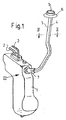
本発明は、自動車用の二次液体容器(2)、特に、注入管(3)および充填抽気導管(4)を備えた洗浄液容器に関する。注入管(3)および充填抽気導管(4)は、二次液体容器(1)の単一の充填抽気接続部(8)における1つの共通した接続断面を介して二次液体容器(1)に接続され、好ましくは一体に形成されたものとする。【選択図】図1The present invention relates to a secondary liquid container (2) for automobiles, in particular a cleaning liquid container provided with an injection tube (3) and a filling bleed conduit (4). The inlet tube (3) and the filling bleed conduit (4) are connected to the secondary liquid container (1) via one common connection section in the single filling bleed connection (8) of the secondary liquid container (1). It is assumed that they are connected and preferably integrally formed. [Selection] Figure 1
Description
本発明は、自動車用の二次液体容器に関し、詳しくは、洗浄液容器に関する。 The present invention relates to a secondary liquid container for automobiles, and more particularly to a cleaning liquid container.
係る二次液体容器は、自動車内に収容されるように、主に構造空間に関して最適化されている。二次液体容器は、いずれにせよ寸法が制限されている自動車エンジン用空間には配置されず、代わりに、たとえばホイールケースの内の1つまたは自動車の後部のサイドトリムの下に配置されることがある。周知の容器は、熱可塑性プラスチックから構成され、多くの場合、押出ブロー成形されている。自動車内における比較的隠蔽される配置の都合上、二次液体容器は、自動車ユーザーが容易にアクセスできる自動車上の位置に取り付けられている長い注入管を備えている。注入管は通常、最大許容液位の領域、即ち床上における容器の上部領域で容器に接続されている。ただし、容器の構成および注入管の取付けによっては、容器内に出る注入管の口が容器の最大許容液位以下の場合にも容器に接続され得る状況を回避できない。充填中の容器の抽気を確保することができるように、周知の容器はブリーディングバルブまたはブリーディングホースのいずれかを備えている。ブリーディングバルブを設けることは構造的に複雑であり、ブリーディングホースの取付けも、特に自動車の最終的組立時に、同様に複雑である。 Such secondary liquid containers are mainly optimized with respect to the structural space so as to be accommodated in a motor vehicle. The secondary liquid container is not arranged in any space for the car engine, which is in any case limited in size, but instead placed, for example, under one of the wheel cases or under the side trim of the car. There is. Known containers are constructed from thermoplastics and are often extrusion blow molded. Due to the relatively concealed arrangement within the vehicle, the secondary liquid container is provided with a long infusion tube that is attached to a location on the vehicle that is easily accessible by the vehicle user. The injection tube is usually connected to the container in the region of maximum allowable liquid level, i.e. the upper region of the container on the floor. However, depending on the configuration of the container and the attachment of the injection pipe, it is impossible to avoid a situation in which the inlet of the injection pipe exiting into the container can be connected to the container even when it is below the maximum allowable liquid level of the container. Known containers are provided with either a bleeding valve or a bleeding hose so as to ensure bleed of the container during filling. Providing the bleeding valve is structurally complex, and the installation of the bleeding hose is equally complex, especially during the final assembly of the automobile.
したがって、本発明が基づいている目的は、この点において、冒頭で述べたタイプの二次液体容器を改善することである。 The object on which the invention is based is therefore to improve in this respect a secondary liquid container of the type mentioned at the outset.
上記目的は、自動車用の二次液体容器、特に洗浄液容器であって、容器に接続されている注入管および注入管に略平行に延在する充填抽気導管を備え、注入管および充填抽気導管が単一の充填抽気接続部で容器に接続されて、充填および抽気が1つの共通した接続断面を介して実現されている二次液体容器によって達成される。このような二次液体容器の注入管の設計は、容器の構造をかなり簡略化する。さらに考えられる二次液体容器は、たとえば、排ガスの選択触媒還元用の尿素容器である。 The object is a secondary liquid container for automobiles, in particular a cleaning liquid container, comprising an injection tube connected to the container and a filling bleed conduit extending substantially parallel to the injection tube, the injection tube and the filling bleed conduit being Connected to the container with a single filling bleed connection, filling and bleed are achieved by a secondary liquid container realized via one common connection cross section. Such a secondary liquid container injection tube design considerably simplifies the structure of the container. Further conceivable secondary liquid containers are, for example, urea containers for selective catalytic reduction of exhaust gases.
たとえば、注入管と充填抽気導管は、一体で製造することができ、それにより、充填抽気導管が車体に個別に取り付けられ、固定される必要がない。この場合、注入管に対して別個に固定および/または接続の必要もない。 For example, the injection tube and the filling bleed conduit can be manufactured in one piece, so that the filling bleed conduit does not need to be individually attached and secured to the vehicle body. In this case, there is no need for separate fixation and / or connection to the injection tube.
充填抽気接続部は、容器内の好ましくは円形断面の貫通開口部として設計され得る。 The filling bleed connection can be designed as a through opening in the container, preferably with a circular cross section.
本発明に係る二次液体容器の特に簡単な変形形態では、注入管が貫通開口部内に解除可能に接続されるように設けられている。この場合、たとえば、貫通開口部は貫通シールを備えていてもよい。それによって自動車内での二次液体容器の取付けはかなり簡略化される。 In a particularly simple variant of the secondary liquid container according to the invention, the injection tube is provided so as to be releasably connected in the through opening. In this case, for example, the through opening may include a through seal. Thereby, the installation of the secondary liquid container in the vehicle is considerably simplified.
本発明に係る二次液体容器の好適な変形形態では、充填抽気導管が、接続部品内に、注入管とは別個に該接続部品の開口断面まで配設されている。換言すれば、充填抽気導管は、接続部品の接続断面内に延ばされている。 In a preferred variant of the secondary liquid container according to the invention, a filled bleed conduit is arranged in the connection part, up to the opening cross section of the connection part, separately from the injection pipe. In other words, the filling bleed conduit is extended in the connection cross section of the connection part.
特に好ましくは、注入管は、断面的に充填抽気接続部に嵌合される接続部品を備えるように設けられ得る。それによって、注入管は、任意の所望の外形を有するように、たとえば一体に形成された充填抽気導管を備えて構成することができ、一方で容器の充填抽気接続部は好ましくは円形断面の貫通開口部を備える。 Particularly preferably, the injection tube can be provided with a connection part that is fitted in section to the filling bleed connection. Thereby, the injection tube can be configured to have any desired profile, for example with an integrally formed filling bleed conduit, while the filling bleed connection of the container is preferably through a circular cross-section. An opening is provided.
接続部品は、好適には、共通接続断面に対する注入管と充填抽気導管との収束部を形成する。 The connecting part preferably forms a converging part between the injection tube and the filling bleed conduit for a common connection cross section.
本発明に係る二次液体容器の好ましい変形形態では、注入管と充填抽気導管は、熱可塑性プラスチック材料から一体的に押出ブロー成形されて設けられる。 In a preferred variant of the secondary liquid container according to the invention, the injection tube and the filling bleed conduit are provided by extrusion blow molding integrally from a thermoplastic material.
接続部品は、たとえば熱可塑性プラスチック材料から射出成形されたものであり得る。 The connecting part can be, for example, injection molded from a thermoplastic material.
接続部品が、その外側周りに少なくとも1つの一体形成されたシールを備える場合、容器の充填抽気接続部の領域における別個の貫通シールは必要なくなる。これに代えて、接続部品は、外側周りに形成されてその中にOリングシールが挿入される溝を備えてもよい。射出成形による熱可塑性プラスチック材料からの接続部品の製造においては、代わりとして、接続部品上に射出成形されている熱可塑性エラストマーからなる外周シールリップも可能である。 If the connection piece comprises at least one integrally formed seal around its outer side, a separate through seal in the area of the filling bleed connection of the container is not necessary. Alternatively, the connecting part may comprise a groove formed around the outside and into which the O-ring seal is inserted. In the production of connecting parts from thermoplastic materials by injection molding, an outer peripheral seal lip made of a thermoplastic elastomer that is injection-molded on the connecting parts is alternatively possible.
本発明に係る二次液体容器の特に簡単かつ代替的な改良形態では、接続部品は、入口直径から接続直径までに少なくとも1つの径方向段部を有し、充填抽気導管が、流入する液体に対して該径方向段部によって形成される流れデッドゾーンの領域で接続されるように設けられる。この場合、たとえば、接続部品、注入管、および充填抽気導管は一体に製造され得る。このようにして、構成部品全体は、たとえば熱可塑性プラスチック材料から押出ブロー成形によって取得することができる。本発明における径方向段部とは、より小さい直径からより大きい直径への直径の変化を意味するものと理解されるべきである。 In a particularly simple and alternative refinement of the secondary liquid container according to the invention, the connecting part has at least one radial step from the inlet diameter to the connecting diameter, and a filled bleed conduit is connected to the incoming liquid. On the other hand, it is provided so as to be connected in the region of the flow dead zone formed by the radial step. In this case, for example, the connecting part, the injection tube and the filling bleed conduit can be manufactured in one piece. In this way, the entire component can be obtained, for example, by extrusion blow molding from a thermoplastic material. A radial step in the present invention should be understood to mean a change in diameter from a smaller diameter to a larger diameter.
あるいは、好ましくは円形の接続断面を有する注入管と接続部品を一体に形成し、好ましくは接続部品の径方向段部の領域で、別個の構成部品としての充填抽気導管をニップルを介して接続部品に接続することが可能である。 Alternatively, the injection pipe and the connection part, preferably having a circular connection cross section, are formed in one piece, preferably in the region of the radial step of the connection part, a separate bleed bleed conduit being connected via the nipple It is possible to connect to.
本発明は、図面に示される2つの実施形態をもって以下に説明される。 The invention will be described in the following with two embodiments shown in the drawings.
まず、本発明に係る二次液体容器1の第1の実施形態を示す図1を参照されたい。二次液体容器1は、自動車用の洗浄液容器として設計されている。説明される実施形態では、二次液体容器は熱可塑性プラスチック材料から一体に押出ブロー成形されている。二次液体容器1の内部には、たとえば、自動車用のフロントガラス洗浄システムに導管2を介して接続されている、洗浄液用の不図示の供給ポンプが配置されている。
Reference is first made to FIG. 1 showing a first embodiment of a
二次液体容器用の注入管は3で示され、充填抽気導管4は該注入管上に一体に形成されている。充電抽気管路と一体形成された注入管3は、例えば、低廃棄物押出ブロー成形として知られるものによるいわゆる3次元ブロー成形としての、たとえば、サクションブロー成形によって製造され得る。注入開口部5を囲む末端部品6は、流入側/充填側で注入管3および充填抽気導管4の上に設置され、二次液体容器1の充填抽気接続部8に断面適合される接続部品7は流出側で注入管3および充填抽気導管4に取り付けられている。充填抽気接続部8は、円形断面を持ち貫通シール9を備えた貫通開口部として設計されている。貫通シール9は、接続部品7のシール座部11と協働するスリーブ形状のシールカラー10を形成している。シール座部11の代わりに、接続部品7は、外周シールリップまたは一体形成された外周シールカラーを備えていてもよい。
The injection pipe for the secondary liquid container is indicated by 3 and the filling bleed
接続部品7は、好ましくは熱可塑性プラスチック材料から射出成形され、充填抽気導管4に接続されており、二次液体容器1から離れた反対側の注入開口部5は、たとえばこの領域で充填抽気導管4と注入管3に溶接されている。
The connecting
特に図5から推測されるように、充填抽気導管4は、接続部品7の内部に、接続部品7の開口断面12内へ延びている。
As can be inferred in particular from FIG. 5, the filling bleed
同様に熱可塑性プラスチック材料から射出成形され得る末端部品6は、同様に充填抽気導管4および注入管3に溶接されている。該末端部品は、不図示の閉鎖フラップによって、または閉塞プラグによって覆うことができる。
The end piece 6 which can likewise be injection-molded from a thermoplastic material is likewise welded to the filling bleed
接続部品7の変形形態では、図6に例示のように、注入管および充填抽気導管4が接続部品の開口断面12から離れた側で該接続部品7に接続されている。接続部品7は、注入管3のおよび充填抽気導管4の円形ではない断面全体/包絡曲線から充填抽気接続部8の断面へのアダプタとして設計され、注入管3および充填抽気導管4は互いに別個に接続部品7の開口断面12内へ配設されていない。代わりに、接続部品7は、充填抽気導管4から充填抽気接続部8の断面まで直径の適応部を画定する。充填抽気導管4は、注入管3を通過する液体における流れデッドゾーンの領域で接続部品7内に配置され、したがって二次液体容器1の充填中に漏れる抽気流は、それにも関わらず、流入する液体と平行に、充填抽気導管4から出てくることができる。
In a variant of the
この場合、接続部品は注入管3と一体であっても良く、また注入管3と接続部品7は一体に製造され得る。接続部品7が、注入管3と充填抽気導管4とがそれぞれ接続される2個のニップルを有することも同様に考えられる。
In this case, the connection part may be integrated with the
特に図1から推察されるように、注入管3および充填抽気導管4は、二次液体容器1の略上部3分の1の設置位置において、具体的には二次液体容器1内部の最大許容液位の若干下方に設定されている領域で接続されている。
As particularly inferred from FIG. 1, the
1 二次液体容器
2 導管
3 注入管
4 充填抽気導管
5 注入開口部
6 末端部品
7 接続部品
8 充填抽気接続部
9 貫通シール
10 シールカラー
11 シール座部
12 開口断面
DESCRIPTION OF
Claims (12)
Applications Claiming Priority (3)
| Application Number | Priority Date | Filing Date | Title |
|---|---|---|---|
| DE102011118929.0 | 2011-11-21 | ||
| DE201110118929 DE102011118929A1 (en) | 2011-11-21 | 2011-11-21 | Secondary fluid tank for a car |
| PCT/EP2012/004683 WO2013075794A1 (en) | 2011-11-21 | 2012-11-10 | Secondary liquid container for a motor vehicle |
Publications (1)
| Publication Number | Publication Date |
|---|---|
| JP2015504387A true JP2015504387A (en) | 2015-02-12 |
Family
ID=47297080
Family Applications (1)
| Application Number | Title | Priority Date | Filing Date |
|---|---|---|---|
| JP2014541559A Pending JP2015504387A (en) | 2011-11-21 | 2012-11-10 | Secondary liquid container for automobile |
Country Status (9)
| Country | Link |
|---|---|
| US (1) | US10676054B2 (en) |
| EP (1) | EP2782799B1 (en) |
| JP (1) | JP2015504387A (en) |
| KR (1) | KR20140103980A (en) |
| CA (1) | CA2856340C (en) |
| DE (1) | DE102011118929A1 (en) |
| IN (1) | IN2014CN04425A (en) |
| RU (1) | RU2565459C1 (en) |
| WO (1) | WO2013075794A1 (en) |
Families Citing this family (5)
| Publication number | Priority date | Publication date | Assignee | Title |
|---|---|---|---|---|
| DE102013008835B4 (en) * | 2013-05-24 | 2023-09-28 | Volkswagen Aktiengesellschaft | Motor vehicle with an additive container, in particular for an SCR reducing agent |
| EP2923875B1 (en) | 2014-03-25 | 2016-05-18 | Magna Steyr Fuel Systems GesmbH | Filling device and method for producing a filling device |
| JP6604997B2 (en) * | 2017-07-06 | 2019-11-13 | 本田技研工業株式会社 | Cooling system |
| DE102018105986A1 (en) * | 2018-03-15 | 2019-09-19 | Mann+Hummel Gmbh | Filling nozzle and liquid container |
| DE102019117640A1 (en) * | 2019-07-01 | 2021-01-07 | Mann+Hummel Gmbh | Pipe component |
Citations (13)
| Publication number | Priority date | Publication date | Assignee | Title |
|---|---|---|---|---|
| US4185844A (en) * | 1978-04-24 | 1980-01-29 | Chrysler Corporation | Fuel tank filler tube assembly |
| US5000333A (en) * | 1985-03-01 | 1991-03-19 | Alfa Romeo Auto S.P.A. | Container for the windshield washing liquid of a car |
| JPH0616108A (en) * | 1990-12-04 | 1994-01-25 | Asmo Co Ltd | Washer tank |
| US5427263A (en) * | 1992-12-31 | 1995-06-27 | Ford Motor Company | Fuel tank assembly |
| JPH082265A (en) * | 1994-06-21 | 1996-01-09 | Futaba Sangyo Kk | Fuel inlet |
| US5853025A (en) * | 1996-01-16 | 1998-12-29 | Daneshvar; Yousef | Windshield fluid delivery system |
| JP2003220627A (en) * | 2001-11-26 | 2003-08-05 | Kunimori Kagaku Co Ltd | Method for manufacturing connection part for fuel tank |
| US20050016619A1 (en) * | 2001-11-09 | 2005-01-27 | Stefan Winterling | Windshield wiper fluid reservoir |
| JP2006111131A (en) * | 2004-10-14 | 2006-04-27 | Jidosha Denki Kogyo Co Ltd | Level gauge for washer tank |
| US20060180958A1 (en) * | 2005-02-17 | 2006-08-17 | Stant Manufacturing Inc. | Method of forming a monolithic element including multiple conduits |
| JP2010070062A (en) * | 2008-09-18 | 2010-04-02 | Toyota Motor Corp | Pipe connection structure |
| FR2936837A1 (en) * | 2008-10-03 | 2010-04-09 | Inergy Automotive Systems Res | Storage reservoir for storing e.g. aqueous urea solution in diesel engine of heavy truck, has filling pipe and aeration tube formed as single piece by molding, where aeration tube sets maximum filling level of reservoir |
| JP2010089702A (en) * | 2008-10-10 | 2010-04-22 | Toyota Auto Body Co Ltd | Inlet and washer tank with the same |
Family Cites Families (43)
| Publication number | Priority date | Publication date | Assignee | Title |
|---|---|---|---|---|
| US2139476A (en) * | 1937-03-30 | 1938-12-06 | Thomas T Townsend | Automatic battery filling device |
| US2798745A (en) * | 1954-02-23 | 1957-07-09 | Lewen R Nelson | Multiple-tube hose coupling |
| DE1784086U (en) * | 1958-07-16 | 1959-02-26 | Westfaelische Metall Industrie | CONTAINER LOCK FOR WINDOW WASHER ON VEHICLES. |
| US3187936A (en) * | 1962-11-01 | 1965-06-08 | Gen Motors Corp | Integral fuel filler pipe and vent tube |
| US3458619A (en) * | 1965-04-13 | 1969-07-29 | Anger Kunststoff | Process for producing molded bodies |
| AT325979B (en) * | 1971-10-26 | 1975-11-25 | Schiemann Dr Wolfram | DEVICE FOR VENTILATING CANISTERS |
| US3838713A (en) * | 1972-10-10 | 1974-10-01 | Tu Co Inc | Trailer tube and connection |
| CA1072026A (en) * | 1976-11-10 | 1980-02-19 | Lee A. Germain | Vapor recovery filler neck assembly |
| US4274549A (en) * | 1979-09-27 | 1981-06-23 | The Goodyear Tire & Rubber Company | Apparatus for fuel vapor recovery |
| US4570686A (en) * | 1983-06-24 | 1986-02-18 | Gilbarco Inc. | Apparatus for preventing blockage of vapor recovery hose by liquid fuel |
| US4730652A (en) * | 1984-11-06 | 1988-03-15 | Proprietary Technology, Inc. | Automotive fuel filler system |
| DK23185A (en) * | 1985-01-17 | 1986-07-18 | Kim Larsen | A CONNECTION HOSE BETWEEN TWO CONTAINERS |
| IT206208Z2 (en) * | 1985-11-15 | 1987-07-13 | Italiana Serrature Torino | FUEL SUPPLEMENT BODY FOR VEHICLES |
| DE3540740A1 (en) * | 1985-11-16 | 1987-05-21 | Porsche Ag | FUEL CONNECTOR FOR A FUEL TANK, ESPECIALLY FOR FUEL VEHICLES |
| US5111858A (en) * | 1990-12-24 | 1992-05-12 | Ford Motor Company | Interengageable plastic fuel flange and plastic filler tube |
| US5466016A (en) * | 1994-04-11 | 1995-11-14 | General Motors Corporation | Solderless filler neck joint |
| DE19524254C1 (en) * | 1995-07-04 | 1997-01-16 | Mc Micro Compact Car Ag | Fuel tank |
| DE19532988C1 (en) * | 1995-09-07 | 1996-12-19 | Porsche Ag | Fuel tank esp. for motor cars |
| IL121159A0 (en) * | 1997-06-24 | 1997-11-20 | Franco Shlomi | Vehicle windshield de-icing apparatus and method |
| US6044517A (en) * | 1998-01-02 | 2000-04-04 | Chrysler Corporation | Apparatus for filling a washer fluid reservoir |
| US6196280B1 (en) * | 1999-08-17 | 2001-03-06 | Liberty Fuels, Inc. | Combination nozzle and fuel tank fitting for delivering liquefied natural gas and components thereof |
| DE19943292C1 (en) * | 1999-09-10 | 2001-05-23 | Porsche Ag | End-side holding device for a vent line of a fuel tank |
| DE10013919A1 (en) * | 2000-03-21 | 2001-09-27 | Mannesmann Vdo Ag | Venting device for a fuel tank |
| US20020117233A1 (en) * | 2001-02-27 | 2002-08-29 | Kellogg Matthew Kenyon | Disposable/reusable lubrication container system |
| JP2002339825A (en) * | 2001-03-16 | 2002-11-27 | Tokai Rubber Ind Ltd | Cylindrical body installing structure to fuel tank |
| EP1463901A4 (en) * | 2001-12-12 | 2007-01-03 | Martinrea Ind Inc | Spud assembly for a fuel tank |
| US6761380B2 (en) * | 2002-05-07 | 2004-07-13 | Delphi Technologies, Inc. | Filler neck assembly for fuel tank |
| DE10234105B4 (en) * | 2002-07-26 | 2006-01-26 | Daimlerchrysler Ag | Liquid container for vehicles |
| FR2844487B1 (en) * | 2002-09-13 | 2005-05-13 | Inergy Automotive Systems Res | SAFETY SYSTEM FOR LIQUID FUEL TANK |
| US6874550B2 (en) * | 2003-04-24 | 2005-04-05 | Goodrich Corporation | Gravity fill line vent fitting and fill system |
| WO2004110756A1 (en) * | 2003-06-17 | 2004-12-23 | Daikin Industries, Ltd. | Laminated resin formed body, method for producing laminated resin formed body, and multilayer article |
| WO2005093382A1 (en) * | 2004-03-29 | 2005-10-06 | Nissan Diesel Motor Co., Ltd. | Structure for reducing agent container |
| JP4564858B2 (en) * | 2005-02-08 | 2010-10-20 | 八千代工業株式会社 | Fuel tank structure |
| ATE485962T1 (en) * | 2005-03-24 | 2010-11-15 | Ems Chemie Ag | USE OF A PIPE SYSTEM FOR FLUIDS WITH VOLATILE COMPONENTS |
| AU2007204557A1 (en) * | 2006-01-09 | 2007-07-19 | Fuel Transfer Technologies Inc. | Liquid delivery system for supplying liquid from a portable container to at least one selected remote destination and removing vapour from the at least one selected remote destination |
| FR2900091B1 (en) * | 2006-04-21 | 2010-09-10 | Inergy Automotive Systems Res | PROCESS FOR THE MANUFACTURE OF A FUEL TANK OF PLASTIC MATERIAL |
| US7735672B2 (en) * | 2006-07-31 | 2010-06-15 | Voss Iii Frederick | Vented non-spill fuel cap assembly with fill indicator |
| DE102006037556B4 (en) * | 2006-08-10 | 2010-04-01 | Thermo-Technik-Systeme Gmbh | Method and blow mold for producing interconnected plastic pipes |
| US20080173358A1 (en) * | 2007-01-18 | 2008-07-24 | James Guldi | System for adding a fuel additive to a fuel tank |
| US8347926B2 (en) * | 2007-02-15 | 2013-01-08 | Voss Intellectual Property, Llc | Portable fuel dispensing system |
| EP2014886A1 (en) * | 2007-07-09 | 2009-01-14 | Delphi Technologies, Inc. | Reservoir for a fluid dosing system |
| NZ585963A (en) * | 2007-11-05 | 2012-05-25 | Lawrence William Hirst | A method and apparatus for recovery of suspended biological material |
| US20120228292A1 (en) * | 2011-03-10 | 2012-09-13 | Stant Usa Corp. | Mount for inlet check valve |
-
2011
- 2011-11-21 DE DE201110118929 patent/DE102011118929A1/en not_active Withdrawn
-
2012
- 2012-11-10 KR KR1020147017037A patent/KR20140103980A/en not_active Application Discontinuation
- 2012-11-10 IN IN4425CHN2014 patent/IN2014CN04425A/en unknown
- 2012-11-10 EP EP12797693.4A patent/EP2782799B1/en active Active
- 2012-11-10 JP JP2014541559A patent/JP2015504387A/en active Pending
- 2012-11-10 CA CA2856340A patent/CA2856340C/en active Active
- 2012-11-10 RU RU2014125068/11A patent/RU2565459C1/en active
- 2012-11-10 US US14/359,448 patent/US10676054B2/en active Active
- 2012-11-10 WO PCT/EP2012/004683 patent/WO2013075794A1/en active Application Filing
Patent Citations (13)
| Publication number | Priority date | Publication date | Assignee | Title |
|---|---|---|---|---|
| US4185844A (en) * | 1978-04-24 | 1980-01-29 | Chrysler Corporation | Fuel tank filler tube assembly |
| US5000333A (en) * | 1985-03-01 | 1991-03-19 | Alfa Romeo Auto S.P.A. | Container for the windshield washing liquid of a car |
| JPH0616108A (en) * | 1990-12-04 | 1994-01-25 | Asmo Co Ltd | Washer tank |
| US5427263A (en) * | 1992-12-31 | 1995-06-27 | Ford Motor Company | Fuel tank assembly |
| JPH082265A (en) * | 1994-06-21 | 1996-01-09 | Futaba Sangyo Kk | Fuel inlet |
| US5853025A (en) * | 1996-01-16 | 1998-12-29 | Daneshvar; Yousef | Windshield fluid delivery system |
| US20050016619A1 (en) * | 2001-11-09 | 2005-01-27 | Stefan Winterling | Windshield wiper fluid reservoir |
| JP2003220627A (en) * | 2001-11-26 | 2003-08-05 | Kunimori Kagaku Co Ltd | Method for manufacturing connection part for fuel tank |
| JP2006111131A (en) * | 2004-10-14 | 2006-04-27 | Jidosha Denki Kogyo Co Ltd | Level gauge for washer tank |
| US20060180958A1 (en) * | 2005-02-17 | 2006-08-17 | Stant Manufacturing Inc. | Method of forming a monolithic element including multiple conduits |
| JP2010070062A (en) * | 2008-09-18 | 2010-04-02 | Toyota Motor Corp | Pipe connection structure |
| FR2936837A1 (en) * | 2008-10-03 | 2010-04-09 | Inergy Automotive Systems Res | Storage reservoir for storing e.g. aqueous urea solution in diesel engine of heavy truck, has filling pipe and aeration tube formed as single piece by molding, where aeration tube sets maximum filling level of reservoir |
| JP2010089702A (en) * | 2008-10-10 | 2010-04-22 | Toyota Auto Body Co Ltd | Inlet and washer tank with the same |
Also Published As
| Publication number | Publication date |
|---|---|
| CA2856340C (en) | 2016-06-21 |
| KR20140103980A (en) | 2014-08-27 |
| IN2014CN04425A (en) | 2015-09-04 |
| DE102011118929A1 (en) | 2013-05-23 |
| RU2565459C1 (en) | 2015-10-20 |
| US20140290756A1 (en) | 2014-10-02 |
| CA2856340A1 (en) | 2013-05-30 |
| EP2782799A1 (en) | 2014-10-01 |
| US10676054B2 (en) | 2020-06-09 |
| WO2013075794A1 (en) | 2013-05-30 |
| EP2782799B1 (en) | 2020-08-19 |
Similar Documents
| Publication | Publication Date | Title |
|---|---|---|
| JP2015504387A (en) | Secondary liquid container for automobile | |
| JP4511945B2 (en) | Support for functional parts of fuel tank and automobile fuel tank provided with support for functional parts | |
| US20100224284A1 (en) | Reducing agent tank | |
| JP5473018B2 (en) | Automotive fuel tank | |
| KR20100115764A (en) | Fuel tank for motor vehicles made of thermoplastic plastic | |
| JP5675835B2 (en) | Intake manifold and intake system | |
| KR20120089689A (en) | Improved filling system for vehicular fluid container | |
| CN103502621B (en) | For carrying the ejector pump of fuel | |
| JP2017538623A (en) | Automobile injection system having at least two storage tanks for liquid or gaseous working substances | |
| KR102371227B1 (en) | Urea solution filler neck device | |
| JP2014525870A (en) | Automotive liquid containers, especially fuel containers | |
| ITTO960661A1 (en) | GROUP OF FUEL TANK OF A VEHICLE. | |
| CN203391612U (en) | Stainless steel oil filling pipe assembly | |
| JP2015081091A (en) | Integrated fluid container structure, and wheel liner splash shield | |
| CN104781096B (en) | Liquid/vapour separator | |
| CN105015323A (en) | Oil filling pipe assembly with flexible structure | |
| JP3107725U (en) | The intake pipe for automobile engines that can be assembled freely with a higher intake volume | |
| CN202082516U (en) | Air conditioner pipe | |
| CN204845525U (en) | Add oil pipe assembly with flexible construction | |
| CA2769661C (en) | Fluid connection device | |
| US10059195B2 (en) | Motor vehicle operating fluid container made of thermoplastic | |
| JP3710366B2 (en) | Structure of the cap for the radiator reserve tank | |
| CN215361311U (en) | Liquid storage tank and brake system | |
| CN203560014U (en) | Air intake device of engine of gasoline car | |
| JP2014121906A (en) | Fuel filler structure for fuel tank |
Legal Events
| Date | Code | Title | Description |
|---|---|---|---|
| A977 | Report on retrieval |
Free format text: JAPANESE INTERMEDIATE CODE: A971007 Effective date: 20150717 |
|
| A131 | Notification of reasons for refusal |
Free format text: JAPANESE INTERMEDIATE CODE: A131 Effective date: 20150722 |
|
| A521 | Request for written amendment filed |
Free format text: JAPANESE INTERMEDIATE CODE: A523 Effective date: 20151022 |
|
| A02 | Decision of refusal |
Free format text: JAPANESE INTERMEDIATE CODE: A02 Effective date: 20151111 |