US2139476A - Automatic battery filling device - Google Patents
Automatic battery filling device Download PDFInfo
- Publication number
- US2139476A US2139476A US13375137A US2139476A US 2139476 A US2139476 A US 2139476A US 13375137 A US13375137 A US 13375137A US 2139476 A US2139476 A US 2139476A
- Authority
- US
- United States
- Prior art keywords
- air
- battery
- slot
- control member
- passageway
- Prior art date
- Legal status (The legal status is an assumption and is not a legal conclusion. Google has not performed a legal analysis and makes no representation as to the accuracy of the status listed.)
- Expired - Lifetime
Links
- XLYOFNOQVPJJNP-UHFFFAOYSA-N water Substances O XLYOFNOQVPJJNP-UHFFFAOYSA-N 0.000 description 48
- 239000007788 liquid Substances 0.000 description 24
- 239000003792 electrolyte Substances 0.000 description 18
- 238000010276 construction Methods 0.000 description 6
- 230000009471 action Effects 0.000 description 5
- 239000007789 gas Substances 0.000 description 5
- 239000000945 filler Substances 0.000 description 4
- 238000004891 communication Methods 0.000 description 3
- 230000000694 effects Effects 0.000 description 3
- 239000012530 fluid Substances 0.000 description 3
- 210000003128 head Anatomy 0.000 description 3
- 238000013022 venting Methods 0.000 description 3
- 229920001875 Ebonite Polymers 0.000 description 2
- 241000237858 Gastropoda Species 0.000 description 2
- 230000005484 gravity Effects 0.000 description 2
- 239000002184 metal Substances 0.000 description 2
- 230000000630 rising effect Effects 0.000 description 2
- 230000003068 static effect Effects 0.000 description 2
- 206010044565 Tremor Diseases 0.000 description 1
- 238000013019 agitation Methods 0.000 description 1
- 230000004075 alteration Effects 0.000 description 1
- 230000036621 balding Effects 0.000 description 1
- 230000008901 benefit Effects 0.000 description 1
- 230000008878 coupling Effects 0.000 description 1
- 238000010168 coupling process Methods 0.000 description 1
- 238000005859 coupling reaction Methods 0.000 description 1
- 230000003292 diminished effect Effects 0.000 description 1
- 230000008020 evaporation Effects 0.000 description 1
- 238000001704 evaporation Methods 0.000 description 1
- 230000008014 freezing Effects 0.000 description 1
- 238000007710 freezing Methods 0.000 description 1
- 230000000717 retained effect Effects 0.000 description 1
Images

Classifications
-
- H—ELECTRICITY
- H01—ELECTRIC ELEMENTS
- H01M—PROCESSES OR MEANS, e.g. BATTERIES, FOR THE DIRECT CONVERSION OF CHEMICAL ENERGY INTO ELECTRICAL ENERGY
- H01M50/00—Constructional details or processes of manufacture of the non-active parts of electrochemical cells other than fuel cells, e.g. hybrid cells
- H01M50/60—Arrangements or processes for filling or topping-up with liquids; Arrangements or processes for draining liquids from casings
- H01M50/609—Arrangements or processes for filling with liquid, e.g. electrolytes
- H01M50/618—Pressure control
-
- Y—GENERAL TAGGING OF NEW TECHNOLOGICAL DEVELOPMENTS; GENERAL TAGGING OF CROSS-SECTIONAL TECHNOLOGIES SPANNING OVER SEVERAL SECTIONS OF THE IPC; TECHNICAL SUBJECTS COVERED BY FORMER USPC CROSS-REFERENCE ART COLLECTIONS [XRACs] AND DIGESTS
- Y02—TECHNOLOGIES OR APPLICATIONS FOR MITIGATION OR ADAPTATION AGAINST CLIMATE CHANGE
- Y02E—REDUCTION OF GREENHOUSE GAS [GHG] EMISSIONS, RELATED TO ENERGY GENERATION, TRANSMISSION OR DISTRIBUTION
- Y02E60/00—Enabling technologies; Technologies with a potential or indirect contribution to GHG emissions mitigation
- Y02E60/10—Energy storage using batteries
-
- Y—GENERAL TAGGING OF NEW TECHNOLOGICAL DEVELOPMENTS; GENERAL TAGGING OF CROSS-SECTIONAL TECHNOLOGIES SPANNING OVER SEVERAL SECTIONS OF THE IPC; TECHNICAL SUBJECTS COVERED BY FORMER USPC CROSS-REFERENCE ART COLLECTIONS [XRACs] AND DIGESTS
- Y10—TECHNICAL SUBJECTS COVERED BY FORMER USPC
- Y10T—TECHNICAL SUBJECTS COVERED BY FORMER US CLASSIFICATION
- Y10T137/00—Fluid handling
- Y10T137/4673—Plural tanks or compartments with parallel flow
- Y10T137/4757—Battery or electrolytic cell replenishment
- Y10T137/4774—Barometric supply
-
- Y—GENERAL TAGGING OF NEW TECHNOLOGICAL DEVELOPMENTS; GENERAL TAGGING OF CROSS-SECTIONAL TECHNOLOGIES SPANNING OVER SEVERAL SECTIONS OF THE IPC; TECHNICAL SUBJECTS COVERED BY FORMER USPC CROSS-REFERENCE ART COLLECTIONS [XRACs] AND DIGESTS
- Y10—TECHNICAL SUBJECTS COVERED BY FORMER USPC
- Y10T—TECHNICAL SUBJECTS COVERED BY FORMER US CLASSIFICATION
- Y10T137/00—Fluid handling
- Y10T137/7287—Liquid level responsive or maintaining systems
- Y10T137/7498—Barometric
-
- Y—GENERAL TAGGING OF NEW TECHNOLOGICAL DEVELOPMENTS; GENERAL TAGGING OF CROSS-SECTIONAL TECHNOLOGIES SPANNING OVER SEVERAL SECTIONS OF THE IPC; TECHNICAL SUBJECTS COVERED BY FORMER USPC CROSS-REFERENCE ART COLLECTIONS [XRACs] AND DIGESTS
- Y10—TECHNICAL SUBJECTS COVERED BY FORMER USPC
- Y10T—TECHNICAL SUBJECTS COVERED BY FORMER US CLASSIFICATION
- Y10T137/00—Fluid handling
- Y10T137/8593—Systems
- Y10T137/86292—System with plural openings, one a gas vent or access opening
- Y10T137/86324—Tank with gas vent and inlet or outlet
- Y10T137/86332—Vent and inlet or outlet in unitary mounting
Definitions
- the present invention relates to improvements 5 in automatic battery lling devices for maintaining the level of the electrolyte in a storage battery cell within certain high and low limits Vof variation.
- the apparatus is designed to act automatically under the control of the level of the electrolyte to add a sufficient quantity of liquid when the surface ofthe electrolyte is low in the battery to raise the level of the electrolyte therein to its high or normal point, and then automatiy 4 cally arrest the operation.
- the invention is applicable to stationary batteries, but is peculiarly eiective for use with batteries supported on moving vehicles in which, owing to the trembling and swaying of the vehicle and its departures from level generally, the electrolyte in the battery is subjected to constant alterations, local or general, in level.
- the present construction is adapted to take advantage of such iuctuations in level of the uid to promote instead of impair effective operation and to prevent an over-supply of fluid to the battery.' f
- the battery to which the invention is applied may be made up of one or a plurality of cells.
- the battery of an automobile has three cells and each cell is suppliedwith replenishing liquid from an independent reservoir connected by conduits to its corresponding cell, each reservoir and cell with their connecting conduits being a distinct system, although the several supply tubes maybe bound together for protection4 and convenience in a single protecting envelope in that part of their length lying between the reservoirs and the battery,
- each storage battery cell is connected with an independent water supply reservoir through two independent conduits, one beingl a water supply tube leading from the reservoir to the battery cell and the other being an air aspirating tube leading from vthe battery cell to the reservoir.
- These independent tubes connect re- 60 spectively with a water supply passageway and an air inlet passageway in the body of a control member that is supported upon the closure cap in the illling opening of the battery cell and projects into the cell with its lower end submerged in' 55 the electrolyte above the plates.
- (o1. 1er-ss) passageway and the water supply passageway are formed with laterally opening ports at different levels in the control member, the port of the Water supply passageway being Just above the bottom wall of the control member and intended s to be permanently submerged in the electrolyte, while the port of the air inlet passageway is on the opposite side oi such-member and at a slightly higher level to determine the minimum level of the electrolyte and, in the construction 10 which is specifically the subject of the present application, opens into a slot which is at an angle to the longitudinal axis of the control member. and which may be so, disposed with relation to such axis that no line parallel tothe plane of ll the slot is normal to such axis.
- each pair of water supply and air inlet tubes leading from the controlmember are attached to a channeled soft rubber stopper removably mounted in the mouth of an inverted bottle, one S0 of which constitutes the water supply reservoir for each battery cell.
- the inner end oi the air inlet channel in the supply reservoir stopper is arranged with a check valve, or has a diminished passage to act approximately like a check valve. 2B in permitting the upward ilowoi air from the vent tube while obstructing the downwardfrilow of liquid into that tube.
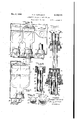
- Figure 1 is a small perspective view illustrating a storage battery oi' three cells communicating through three pairs of tubes with threewater supply reservoirs in the form o! inverted bottles removably mounted in a supporting box or case
- Figure 2 is an enlarged detail sectional view showing the essential parts of-one o! the reservoir bottles with removable stopper and contheir supporting case.
- Figure 3 is 'a detail side elevation illustrating the preferred form of the automatic control member and the means of mounting it in the battery cell.
- Figure 4 is a cross sectional view of the control member taken on the line ri-i or Figure 3.
- FIG. 5 is a detail perspective view of the control member of preferred form.
- Figure 6 is an elevation, parts removed, and others shown in section, of the reservoirs and Figure 7 is a sectional elevation taken in a plane normal to that illustration in Figure 6.
- Figure 8 is an axial or vertical sectional view of a modiiied form of control member.
- Figure 9 is a horizontal sectional view of the same, the plane of section being indicated by the line Q oi Figure 8, and the line oi sight, as indicated by the arrows, parallel to the axis oi the control member.
- Figure lll is a view similar to Figure 2 illustrating other modications.
- Figure li is a view like Figure -9 of the form shown in Figure lll, as indicated by line lll-i l, on Figure le.
- Figure l2 is a detail view of the metal ring forming part oi the bottle hinge
- Figure i3 is a view ci" the outside face ci the reservoir stopper.
- any suitable raclr or case indicated at i supports three inverted bottle reservoirs i which are removably retained in the rack l by any suitable means such for instance as the spring nngers or clips indicated at t.
- each ⁇ or" the bottle reservoirs 2 is provided with :a removable soft rubber stopper ii having means, such as indicated at t, in the form oi metal arms which engage in eyes l formed by curving the base of rack i, which retain the arms from accidental dislodgment and allow them to swing at the bottom in a manner to enable the reservoirs to be individually moved ford on the hinge members t and l as an axis, to disengage the bottle from the spring clips il and enable the op-1 erator to iree the bottle from the stopper il and replenish the water therein, after which the bottle is again closed by engagement of'its stopper and returned to its inverted vertical pcsition as shown.
- a removable soft rubber stopper ii having means, such as indicated at t, in the form oi metal arms which engage in eyes l formed by curving the base of rack i, which retain the arms from accidental dislodgment and allow them to swing at the bottom in a manner to enable the reservoirs
- Two independent flexible' tubes communicate with each of the Stoppers i5, as hereinafter :more specifically described, and the three pairs or tubes from the Stoppers of the three bottle reservoirs are brought together and bound into a common cable indicated at t which passes downwardly to the storage battery with which the lling reser-s voirs are to cooperate.
- each battery cell is in communication with one of the bottle reservoirs 'at 25 to complete the series of vents byJ arcane through two flexible tubes, one of the tubes being the water supply tube and the other the air inlet tube by which the operation of the automatic battery ller is controlled.
- the structure of the automatic filling device is the same for each of the battery cells making up the storage battery so that a detailed explanation of the apparatus and its operation as applied to a single cell will make it clear that the described devices are duplicated for every battery cell forming part of the complete battery.
- the soft rubber stopper 5 is molded with a deep narrow slot i2 so as to present a exible neck l2" approximately elliptical in cross-section, axially through which are extended the longitudinal water supply passageway i3 and the air inlet passageway ld.
- the passageway i3 opens freely into the bottle reservoir while the passageway it is preferably provided at its inner end with means to permit the passage of air from the passageway ll into the bottle reservoir while obstructing the downward passage of water as by a check valve or by the provision of a small opening i5 at the peak of a teat with which the passageway lll ends.
- l@ is a small bore ⁇ exible rubber tube having its upper end i'ltting snugly in and forming a contlnuation of the water supply passageway itl or the stopper 5.
- ible tube having lits upper end snugly tting in the air venting 'passageway irl ci the stepper 5.
- ll is a similar small bore fiex- These tubes it and il pass from the three stoppers ii through a channel casing it to a central coupling sleeve is where the three pairs of tubes are brought closely together and coniined by any suitable tubular covering to form the iiexible cable il of the cluster of tubes.
- Various improvements shown in the reservoir end oi the system are not claimed herein .and will be made the subject of separate applications.
- rI'his control member is formed with one or more venting grooves 22 in the head 2i which expand downwardly in a plane radial to the member so as to allow a vented way from the interior oi the cap il to the outer air, permitting free f passage of gases set free in the cell and keeping the interior of the cell at atmospheric pressure.
- the control member 2d is. formed with a series (four are shown) kof interrupted ribs 23 engaging -a circular rounded rib 2d on the interior of the cap li adjacent to the control member.
- control member This construction enables the control member to be removed or to-be adjusted in height for different batteries, which, in practice, vary as to the amount oi space between the battery plates and the cell top. It is desirable to have the control member adjusted as lowin the cell as is per'- ribs 23 are broken away as shown in Figure 5 whichv the interior of the cell is placed in vcommunica.-
- the cap Il is chambered at
- tubes I6 and I1 are led to and seated closely within the upper ends of water passage 26 and air passage 21, the water passage Abeing reduced in diameter below the end of tube I6.
- I have found W64 and 11/64 of an inch effec'- tive relative diameters of the passages below the tubes I6, I1.
- 1 are V sealed at 28 where they pass through the recess 29 in theihead 2
- the water supply passage 26 has an outlet port at 3
- An inclined slot 33 is made in the lower part of the control mem-v ber on the air passage side. thereof, in which slot the air passage 21 ends at 34 as shown in Figure 2.
- the angle of inclination of the slot is preferably approximatelythat shown and the slot may be inclined as shown only with reference to one plane parallel to the axis of the control member or with reference also to a plane normal to the first plane.
- the surfaces of the slot and the 'edge of the inlet passage 34 lying in such inclined plane are elliptical, and opening 34, Which forms the port to the air passage, is a single opening' elongated in the plane of the slot, so that its ends are presented at different distances from the lower end of the control member and further away from said lower end than the Water supply port. 'Ihe air and liquid in the cell has access to the/'air passage 21 only through the slot 33.
- the lower end 34 of the passage 21 is placed at a height above the bottom of the control member'determined by the margin of variation allowed for the liquid level in the cell.
- the width of the slot which maybe 11g inch or less and the area of the surfaces 35 of the slot around the passage 21 are such that the surface tensionV and capillary attraction will cause the liquid to act as a seal -to the air inlet and so control the refilling operation as will be described.
- the width of the slot and the area of the surfaces thereof will therefore (other conditions remaining constant) be determined by the desired speed of water feeding-a narrower slot and/or increased area of the slot surfaces being adapted.
- the air passage having 'only a single opening 34 there can be no surging of turbulent currents through the lower end of the control member and the tendency of such currents to flow past the inlet 34 is also resisted by the narrowness of the slot 33 and the area of surfaces 35.
- the electrolyte fills the battery above the plates to a height somewhat above the upper edge of inlet 34 with a safe margin between the electrolyte level and the underside of battery top 9.
- the air within the battery is at atmospheric pressure. Gas evolved in the battery escapes between the control member and the closure cap through the vents 22, 25. There is no aperture into the control member to be entered by vertically rising gas bubbles evolved in the cell which might, by rising into the reservoir, cause false operation of the refilling apparatuswhose operation should be due only to the loss of electrolyte.
- the air tube leading to the reservoir could not serve as the second outlet because as soon as a bubble of air reached the bottom of the air tube a surface tension was set up across the bottom of theair tube which blocked passage of liquid up the tube.
- the presence of relatively large capillary surfaces around the inlet 34 of the control member here disclosed seems to assist the liquid to pass out of the inlet while an air bubble is pressing in at the top.
- the bottom of the slot 33 being submerged, there is no point at which surface tension is set up to interfere with the downward movement of the liquid in the slot 33, and the drag of gravity tending to pull the liquid down the sloping surface of the slot helps to draw a drop of water out of the air chamber to make room for the entering bubble of air.
- the slot and inlet will be exposed to the air in the battery for brief and interrupted periods before the liquid level as a whole has lowered to that point.
- the pressure of the air and the pull of gravityupon the liquid which iills the slot will ultimately overcome the resist-4 ance due to surface tension and capillarity, resulting in the admission of a bubble of air to the air passage 21, the admission acting earlier, and in smaller quantities, and so tending to replenish the battery in smaller graded increments battery is at rest.
- the circulation begins when a suflicient column of air accumulates in the air passageway 21 to unbalance the system enough to overcome the surface tension at the mouth of the tube il.
- the circulation may accelerate when 'this initial body of air enters the tube il and becomes elongated, thus accentuating the unbalance of the system. But when this body of air has escaped into the reservoir, the air tube is left filled with bubbles of ⁇ airv separated by slugs of water.
- the air bubbles in the tube il become fewer, until the unbalance of the system is no longer. suiiicient to overcome the surface tension at the mouth of tube l1.
- 'I'his stops the circulation until the level of the electrolyte drops enough to-let in more air bubbles. Thesystem is maintained so nearly ata balance, the passages are so small,
- both air and water passages and the air and water passages communicate at their foot, while in the form shown in Figures and Il ⁇ the air passage is branched as shown at 36, 38 and both branches are open to the water passage at the foot'.
- the form shown in ⁇ E igure I0 has an air chamber 25a with which theupper ends of both air branches 36 and 36a communi- The control member 'and the cap walls are iliear enough together to secure engagement ai!
- the engaging means as 'for example, the ribs v24', positively enough to hold these'members from f accidental relative axial movement, but the t of the control member in the cap is loose enough to provide passageway for escaping gas while the entraine'd liquid will flow back through the venting A grooves.
- t e Y In the form of reservoir mounting, shown in Figures 2 and l2, the arms 6 project laterally ⁇ from an elongated ring ta embedded in the head of the stopper so that only the arms project for engagement with the hinge eyes l.
- the neck H2B is divided from the body of the stopper head by the slot I2 nearly to the plane of the bottle rim.
- A- control member for an automatic battery filler adapted to be supported in a battery cell, formed with air and water passageways, communicating at their lower ends, the water passageways having a water .supply port at its lower end, tlm air passageway having an air inlet port above the water supply port and the control member having an inclined narrow open y slot communicating with both passageways.
- a contro! member for an automatic battery filler adapted to be supported in a battery cell
- a battery ller plug comprising 'a hollowed 'out closure cap having an engaging ridge on its inner surface, and a battery illler control member having a series of vented ridges engaging at variable positions the ridge on the cap.
- a battery filler plug comprising a hollowed out closure cap member and a battery filler con trol member inserted therein, one of said members :I4
- a control member for automatically controlling the flow of water from a reservoir to a battery cell, said member being adapted to 'be v7'5 supported in a battery cell 'and formed with water supply and air inlet passageways, said member having a narrow slanting slot near its lower end intersecting at least a large part of said air inlet passageway and forming opposed lips of largeter supply and air inlet passageways, said air inlet' passageway being intersected by a slot extending out through the side of said member, said slot being bounded by closely separated upper and lower lips, the aperture of said slot at the outer wall of said control member having a considerably greater extent in the direction transverse to the axis of said control member than in the direction parallel to the axis of said control member and being characterized by a portion extending above the highest point of the intersection of said slot with said air passageway, said water supply passageway being opened to the space within said battery cell below said intersection.
- a control member for automatically controlling the flow of water from a reservoir to a battery cell, said member being adapted to be supported in a battery cell and formed with water supply and air inlet passageways, said member being cut by a slot near its lower end which intersects said air inlet passageway and is bounded by two plane walls suililciently close together to cause a substantial capillary eiect, said slot being inclined so that a portion of it extends above the level of the intersection of the slot with said air passageway, said water supply passageway being opened to the space within said battery cell below said intersection.
- a control member for automatically controlling the flow of water from a reservoir to a battery cell, said member being adapted to be supported in a battery cell and formed with Water supply and air inlet passageways, said member having a single narrow slot near its lower end intersecting said air inlet passageway, said slot being open to the interior of the battery cell on opposite sides of said air inlet passageway and throughout the intervening portion of one side of the circumference of the control member, said slot being slanted so that one end is higher than the other and being bounded by Walls suiiiciently close together to have a substantial capillary effect, said water supply passageway being opened to the interior cf the battery cell below said intersection.
- a control member for automatically controlling the flow of water from a reservoir to a battery cell, said member being adapted to be supported in a battery cell and formed with water supply and air inlet passageways, and with a slot lying in a plane angular to the vertical axis of the member and having parallel walls suiiiciently close together to cause a substantial capillary effect and bounded by the exterior wall oi the member in a continuous line, said slot intersecting said air inlet'passageway to form a single port therein communicating with the battery interior only through said slot, the Water supply passageway having a port below the air passageway port.
Landscapes
- Chemical & Material Sciences (AREA)
- Chemical Kinetics & Catalysis (AREA)
- Electrochemistry (AREA)
- General Chemical & Material Sciences (AREA)
- Filling, Topping-Up Batteries (AREA)
Description
Dec. 6, l938. T: T', 'rowNsEND 2,139,476
AUTOMATIC BATTERY FILLING DEVICE Filed March 5o, 1957 2 sheets-sheet 1 M UWM ATTORNEYS Dec. 6, 1938. T. T, TowNsEND AUTOMATIC BATTERY FILLING DEVICE 2 Sheets-Sheet 2 Filed March 50, 1937 ATTO RNEYS BYJMMM M 5. T .y////// oa Imm-m Patented Dec. 6, 1938 UNITED STATES PATENT. OFFICE.
aussie sommano-narran mmc navxcn Thomas T. Townsend', New` York, N. Y.
Application March 30,
Claims..
v This application is a continuation in part of mysapplication, Serial No. 13,998, filed April l, 193 f The present invention relates to improvements 5 in automatic battery lling devices for maintaining the level of the electrolyte in a storage battery cell within certain high and low limits Vof variation. The apparatus is designed to act automatically under the control of the level of the electrolyte to add a sufficient quantity of liquid when the surface ofthe electrolyte is low in the battery to raise the level of the electrolyte therein to its high or normal point, and then automatiy 4 cally arrest the operation. 'Ihe construction and l5 principle of operation'are such as to restore 'the liquid level in the battery without vdanger of flooding, which has been a serious difficulty in prior devices of this character.
lThe invention is applicable to stationary batteries, but is peculiarly eiective for use with batteries supported on moving vehicles in which, owing to the trembling and swaying of the vehicle and its departures from level generally, the electrolyte in the battery is subjected to constant alterations, local or general, in level. The present construction is adapted to take advantage of such iuctuations in level of the uid to promote instead of impair effective operation and to prevent an over-supply of fluid to the battery.' f
'I'he battery to which the invention is applied may be made up of one or a plurality of cells. Usually the battery of an automobile has three cells and each cell is suppliedwith replenishing liquid from an independent reservoir connected by conduits to its corresponding cell, each reservoir and cell with their connecting conduits being a distinct system, although the several supply tubes maybe bound together for protection4 and convenience in a single protecting envelope in that part of their length lying between the reservoirs and the battery,
In carrying out the purposes of the present invention, each storage battery cell is connected with an independent water supply reservoir through two independent conduits, one beingl a water supply tube leading from the reservoir to the battery cell and the other being an air aspirating tube leading from vthe battery cell to the reservoir. These independent tubes connect re- 60 spectively with a water supply passageway and an air inlet passageway in the body of a control member that is supported upon the closure cap in the illling opening of the battery cell and projects into the cell with its lower end submerged in' 55 the electrolyte above the plates. 'Ihe air inlet 1931, sensi Ns. 133,151
(o1. 1er-ss) passageway and the water supply passageway are formed with laterally opening ports at different levels in the control member, the port of the Water supply passageway being Just above the bottom wall of the control member and intended s to be permanently submerged in the electrolyte, while the port of the air inlet passageway is on the opposite side oi such-member and at a slightly higher level to determine the minimum level of the electrolyte and, in the construction 10 which is specifically the subject of the present application, opens into a slot which is at an angle to the longitudinal axis of the control member. and which may be so, disposed with relation to such axis that no line parallel tothe plane of ll the slot is normal to such axis. The upper ends of each pair of water supply and air inlet tubes leading from the controlmember are attached to a channeled soft rubber stopper removably mounted in the mouth of an inverted bottle, one S0 of which constitutes the water supply reservoir for each battery cell. The inner end oi the air inlet channel in the supply reservoir stopper is arranged with a check valve, or has a diminished passage to act approximately like a check valve. 2B in permitting the upward ilowoi air from the vent tube while obstructing the downwardfrilow of liquid into that tube.
The ilooding of the battery which has occurred with some prior devices has principally-been due 30 to the disturbance of the static conditions in the system by the dynamic action of the surging electrolyte in the battery cells of a-nrioving` automobile. My copending application. Seria1.No..133,f
752, describes a means of controlling these dy- $5 namic forces by balding. The present application covers another means oi preventing the static conditions within the system from' being interfered with by the surging of the electrolyte, namely, by the utilization of relatively large cspil- 40 lary surfaces at the port or ports entering the air passageway.
' In order that the invention may be fully un` derstood, it will nrst be described with reference to the accompanying drawings, and the novelty will afterwards be pointed out in the annexed claims. In said drawingsy Figure 1 is a small perspective view illustrating a storage battery oi' three cells communicating through three pairs of tubes with threewater supply reservoirs in the form o! inverted bottles removably mounted in a supporting box or case Figure 2 is an enlarged detail sectional view showing the essential parts of-one o! the reservoir bottles with removable stopper and contheir supporting case.
nected through water supply and air tubes with the control memberv removably mounted in the ililing opening of a battery cell.
Figure 3 is 'a detail side elevation illustrating the preferred form of the automatic control member and the means of mounting it in the battery cell. l I
Figure 4 is a cross sectional view of the control member taken on the line ri-i or Figure 3.
Figure 5 is a detail perspective view of the control member of preferred form.
Figure 6 is an elevation, parts removed, and others shown in section, of the reservoirs and Figure 7 is a sectional elevation taken in a plane normal to that illustration in Figure 6.
Figure 8 is an axial or vertical sectional view of a modiiied form of control member.
Figure 9 is a horizontal sectional view of the same, the plane of section being indicated by the line Q oi Figure 8, and the line oi sight, as indicated by the arrows, parallel to the axis oi the control member.
Figure lll is a view similar to Figure 2 illustrating other modications.
Figure li is a view like Figure -9 of the form shown in Figure lll, as indicated by line lll-i l, on Figure le.
Figure l2 is a detail view of the metal ring forming part oi the bottle hinge, and
Figure i3 is a view ci" the outside face ci the reservoir stopper.
Referring to Figures l, 6 and 'l of the drawings, it will be observedt'nat any suitable raclr or case indicated at i supports three inverted bottle reservoirs i which are removably retained in the rack l by any suitable means such for instance as the spring nngers or clips indicated at t. Each `or" the bottle reservoirs 2 is provided with :a removable soft rubber stopper ii having means, such as indicated at t, in the form oi metal arms which engage in eyes l formed by curving the base of rack i, which retain the arms from accidental dislodgment and allow them to swing at the bottom in a manner to enable the reservoirs to be individually moved ford on the hinge members t and l as an axis, to disengage the bottle from the spring clips il and enable the op-1 erator to iree the bottle from the stopper il and replenish the water therein, after which the bottle is again closed by engagement of'its stopper and returned to its inverted vertical pcsition as shown.
Two independent flexible' tubes communicate with each of the Stoppers i5, as hereinafter :more specifically described, and the three pairs or tubes from the Stoppers of the three bottle reservoirs are brought together and bound into a common cable indicated at t which passes downwardly to the storage battery with which the lling reser-s voirs are to cooperate.
9 indicates a storage battery of standard design having three cells with screw-threaded lling openings indicated at it (see Figures 2 and 10) normally closed by the screw caps Il, in which are freely mounted the control members hereinafter described. In Figure 1 the cable of flexible tubes is divided adjacent to the battery 9 into three separate pairs of tubes which communicate with passageway/s in the control members of the three battery cells in the manner hereinafter explained. With this arrangement it will be observed that each battery cell is in communication with one of the bottle reservoirs 'at 25 to complete the series of vents byJ arcane through two flexible tubes, one of the tubes being the water supply tube and the other the air inlet tube by which the operation of the automatic battery ller is controlled. It will be understood further that the structure of the automatic filling device is the same for each of the battery cells making up the storage battery so that a detailed explanation of the apparatus and its operation as applied to a single cell will make it clear that the described devices are duplicated for every battery cell forming part of the complete battery.
Referring to Figure 2 of the drawings it will be observed that the soft rubber stopper 5 is molded with a deep narrow slot i2 so as to present a exible neck l2" approximately elliptical in cross-section, axially through which are extended the longitudinal water supply passageway i3 and the air inlet passageway ld. The passageway i3 opens freely into the bottle reservoir while the passageway it is preferably provided at its inner end with means to permit the passage of air from the passageway ll into the bottle reservoir while obstructing the downward passage of water as by a check valve or by the provision of a small opening i5 at the peak of a teat with which the passageway lll ends.
l@ is a small bore` exible rubber tube having its upper end i'ltting snugly in and forming a contlnuation of the water supply passageway itl or the stopper 5. ible tube having lits upper end snugly tting in the air venting 'passageway irl ci the stepper 5.
ll is a similar small bore fiex- These tubes it and il pass from the three stoppers ii through a channel casing it to a central coupling sleeve is where the three pairs of tubes are brought closely together and coniined by any suitable tubular covering to form the iiexible cable il of the cluster of tubes. Various improvements shown in the reservoir end oi the system are not claimed herein .and will be made the subject of separate applications.
it will oi" course be understood that the rack l supporting the inverted bottle reservoirs 2 is designed to be supported ata suficient elevation above the storage battery that is to be served,`to insure the water flowing from the reservoirs to the battery cells by'gravity under control of the improved control members and supported in the lling openings of the battery cells. Figures 2 to 5 show the preferred form of the control member e as consisting or" a substantially cylindrical shaped body il@ of hard rubber or the like formed with suitable passageways, presently to be referred to,v
and withan enlarged recessed head 2l shouldered to rest upon a shoulder 2te of the hollcwed out 1 cap ii. rI'his control member is formed with one or more venting grooves 22 in the head 2i which expand downwardly in a plane radial to the member so as to allow a vented way from the interior oi the cap il to the outer air, permitting free f passage of gases set free in the cell and keeping the interior of the cell at atmospheric pressure. The control member 2d is. formed with a series (four are shown) kof interrupted ribs 23 engaging -a circular rounded rib 2d on the interior of the cap li adjacent to the control member. This construction enables the control member to be removed or to-be adjusted in height for different batteries, which, in practice, vary as to the amount oi space between the battery plates and the cell top. It is desirable to have the control member adjusted as lowin the cell as is per'- ribs 23 are broken away as shown in Figure 5 whichv the interior of the cell is placed in vcommunica.-
tion with the atmosphere. The cap Il is chambered at |Il to provide, in association with the large 4vent passages, for the settling out of liquid entrained by the escaping gas.
The lower ends of tubes I6 and I1 are led to and seated closely within the upper ends of water passage 26 and air passage 21, the water passage Abeing reduced in diameter below the end of tube I6. I have found W64 and 11/64 of an inch effec'- tive relative diameters of the passages below the tubes I6, I1. The lower ends oftubes I6, |1 are V sealed at 28 where they pass through the recess 29 in theihead 2| of the control member and a disk of semi-hard rubber may be pressed into engagement with the angularly ridged seat 30 of the control member to protect the joint. l
' The water supply passage 26 has an outlet port at 3| immediately above the bottom wall 32 of the control member, which wail is imperforate and approximately horizontal in the normal position of said member. In normal operation, the port 3| is permanently submerged. The passages 26 and 21 are not in communication andthere is no possibility, therefore, that surging of the battery fluid vthrough the control member will disturb the action of the apparatus. An inclined slot 33 is made in the lower part of the control mem-v ber on the air passage side. thereof, in which slot the air passage 21 ends at 34 as shown in Figure 2. The angle of inclination of the slot is preferably approximatelythat shown and the slot may be inclined as shown only with reference to one plane parallel to the axis of the control member or with reference also to a plane normal to the first plane. The surfaces of the slot and the 'edge of the inlet passage 34 lying in such inclined plane are elliptical, and opening 34, Which forms the port to the air passage, is a single opening' elongated in the plane of the slot, so that its ends are presented at different distances from the lower end of the control member and further away from said lower end than the Water supply port. 'Ihe air and liquid in the cell has access to the/'air passage 21 only through the slot 33. The lower end 34 of the passage 21 is placed at a height above the bottom of the control member'determined by the margin of variation allowed for the liquid level in the cell. The width of the slot which maybe 11g inch or less and the area of the surfaces 35 of the slot around the passage 21 are such that the surface tensionV and capillary attraction will cause the liquid to act as a seal -to the air inlet and so control the refilling operation as will be described. The width of the slot and the area of the surfaces thereof will therefore (other conditions remaining constant) be determined by the desired speed of water feeding-a narrower slot and/or increased area of the slot surfaces being adapted.
to slow up the action.
The air passage having 'only a single opening 34, there can be no surging of turbulent currents through the lower end of the control member and the tendency of such currents to flow past the inlet 34 is also resisted by the narrowness of the slot 33 and the area of surfaces 35.
The above-described apparatus has been found in practice to operate well in automatically replnishing the liquid in a battery cell as frequentlyl as required by the dropping of the electrolyte level below the minimum at which the plates are covered to a safe depth, and without excessive supply of liquid from the reservoir such as to result in flooding the,batterywith consequent subjection of the contiguous parts to corroding action. I present the following as a theory consistent with observations made of the apparatus in operation, without intending to imply that the invention is limited to the operation here described. 4
Normally the electrolyte fills the battery above the plates to a height somewhat above the upper edge of inlet 34 with a safe margin between the electrolyte level and the underside of battery top 9. Owing to the vented construction of the battery closure, the air within the battery is at atmospheric pressure. Gas evolved in the battery escapes between the control member and the closure cap through the vents 22, 25. There is no aperture into the control member to be entered by vertically rising gas bubbles evolved in the cell which might, by rising into the reservoir, cause false operation of the refilling apparatuswhose operation should be due only to the loss of electrolyte. With the reservoir properly charged -in the reservoir, with pressure in the reservoir below atmospheric to an extent measured by the height of the water column between the liquid levels in battery and reservoir.
As the electrolyte level in the battery lowers by reason of evaporation and battery activity it reaches the upper edge of the slot 33 and thereafter the upper edge of the air inlet 34. Surface tension and capillary attraction cause the fluid filling the slot 33'to restrain the passage of air into'inlet 34 until the level of liquid in the battery jar drops considerably below the upper edge of inlet 34 before the air can penetrate through the inlet. In control members used heretoforethe air inlet has been in the form of a small hole through a thin wall surrounding the air chamber. With this construction the surface tension at the air inlet apparently prevented liquid from passing out of the inlet at the same time an air bubble was trying to enter the inlet. It was therefore necessary to provide a second outlet for the liquid. The air tube leading to the reservoir could not serve as the second outlet because as soon as a bubble of air reached the bottom of the air tube a surface tension was set up across the bottom of theair tube which blocked passage of liquid up the tube. The presence of relatively large capillary surfaces around the inlet 34 of the control member here disclosed seems to assist the liquid to pass out of the inlet while an air bubble is pressing in at the top. The bottom of the slot 33 being submerged, there is no point at which surface tension is set up to interfere with the downward movement of the liquid in the slot 33, and the drag of gravity tending to pull the liquid down the sloping surface of the slot helps to draw a drop of water out of the air chamber to make room for the entering bubble of air.
If the automobile on which the apparatus is mounted is in motion, with resulting agitation of the surface of the liquid, the slot and inlet will be exposed to the air in the battery for brief and interrupted periods before the liquid level as a whole has lowered to that point. In either case, whether at rest or in motion, the pressure of the air and the pull of gravityupon the liquid which iills the slot will ultimately overcome the resist-4 ance due to surface tension and capillarity, resulting in the admission of a bubble of air to the air passage 21, the admission acting earlier, and in smaller quantities, and so tending to replenish the battery in smaller graded increments battery is at rest.
if the battery is in motion than is the case if the When the surface tension is broken and the air begins 'to enter the inlet, the inclined surface of the slot tends to assist the drainage from the passageway. Thus this form of my device is independent of a separate in the slot, letting air into the air inlet in bubf bles which'pass up through the air passage preceded and followed by slugs of liquid. There lmay be a delay in the beginning of circulation upward in the air tube and downward in the water tube, due to surface tension set up across the mouth of the air tube il when an air bubble reaches that point. `The circulation begins when a suflicient column of air accumulates in the air passageway 21 to unbalance the system enough to overcome the surface tension at the mouth of the tube il. The circulation may accelerate when 'this initial body of air enters the tube il and becomes elongated, thus accentuating the unbalance of the system. But when this body of air has escaped into the reservoir, the air tube is left filled with bubbles of `airv separated by slugs of water. As the level of the electrolyte in the battery cell rises, the air bubbles in the tube il become fewer, until the unbalance of the system is no longer. suiiicient to overcome the surface tension at the mouth of tube l1. 'I'his stops the circulation until the level of the electrolyte drops enough to-let in more air bubbles. Thesystem is maintained so nearly ata balance, the passages are so small,
` and the unbalance when it occurs is so slight,
that Veven the slight resistance of the surface tension affords an effective valve to graduate the flow. The battery cell is never flooded because the air is measured in small -bubbles segregated by water and there is never a direct air communication between the reservoir and the outer atmosphere; also because the system is effectively shielded from the dynamic action of the swaying electrolyte in the battery cell. (The direction of flow in the air passage is upward and the resulting downward iiow in the water -passage to refill the cell takes place without sudden flooding.) The circulation maintained soon' results in equal densities in battery and reservoir, with consequent lessening of chance of freezing .the liquid in the reservoir and connecting tubes.
In the form of the invention shown in Figures 8 and 9, the water outlet 3| -is placed-as before at the foot of the Water passage 2,6, the
I claim:-
A1. A- control member for an automatic battery filler adapted to be supported in a battery cell, formed with air and water passageways, communicating at their lower ends, the water passageways having a water .supply port at its lower end, tlm air passageway having an air inlet port above the water supply port and the control member having an inclined narrow open y slot communicating with both passageways. l
2. A contro! member for an automatic battery filler adapted to be supported in a battery cell,
formed with a water supply passageway having a discharge port at the lower end of the control member, a separate air passageway having an air chamber and branched below saidair chamber, the several passageways communicating at the lower end of the `control member, and having a single inclined openslot opening'` intoall the passageways.
3. A battery ller plug comprising 'a hollowed 'out closure cap having an engaging ridge on its inner surface, and a battery illler control member having a series of vented ridges engaging at variable positions the ridge on the cap.
4. A battery filler plug comprising a hollowed out closure cap member and a battery filler con trol member inserted therein, one of said members :I4
vhaving a narrow slanting slot near its lower end' intersecting said air inlet passageway and form- Y ing closely opposed lipsrextending in a direction transverse to the longitudinal axis of saidI control member for a distance considerably greater f thanvthe distance between the lips, one end of said slot-extending above the intersection of said slot and said air passageway, said water supply passageway being opened to the space within the v battery cell/below said intersection. I
6. A control member `for automatically controlling the flow of water from a reservoir to a battery cell, said member being adapted to 'be v7'5 supported in a battery cell 'and formed with water supply and air inlet passageways, said member having a narrow slanting slot near its lower end intersecting at least a large part of said air inlet passageway and forming opposed lips of largeter supply and air inlet passageways, said air inlet' passageway being intersected by a slot extending out through the side of said member, said slot being bounded by closely separated upper and lower lips, the aperture of said slot at the outer wall of said control member having a considerably greater extent in the direction transverse to the axis of said control member than in the direction parallel to the axis of said control member and being characterized by a portion extending above the highest point of the intersection of said slot with said air passageway, said water supply passageway being opened to the space within said battery cell below said intersection. f
8. A control member for automatically controlling the flow of water from a reservoir to a battery cell, said member being adapted to be supported in a battery cell and formed with water supply and air inlet passageways, said member being cut by a slot near its lower end which intersects said air inlet passageway and is bounded by two plane walls suililciently close together to cause a substantial capillary eiect, said slot being inclined so that a portion of it extends above the level of the intersection of the slot with said air passageway, said water supply passageway being opened to the space within said battery cell below said intersection.
9. A control member for automatically controlling the flow of water from a reservoir to a battery cell, said member being adapted to be supported in a battery cell and formed with Water supply and air inlet passageways, said member having a single narrow slot near its lower end intersecting said air inlet passageway, said slot being open to the interior of the battery cell on opposite sides of said air inlet passageway and throughout the intervening portion of one side of the circumference of the control member, said slot being slanted so that one end is higher than the other and being bounded by Walls suiiiciently close together to have a substantial capillary effect, said water supply passageway being opened to the interior cf the battery cell below said intersection.
10. A control member for automatically controlling the flow of water from a reservoir to a battery cell, said member being adapted to be supported in a battery cell and formed with water supply and air inlet passageways, and with a slot lying in a plane angular to the vertical axis of the member and having parallel walls suiiiciently close together to cause a substantial capillary effect and bounded by the exterior wall oi the member in a continuous line, said slot intersecting said air inlet'passageway to form a single port therein communicating with the battery interior only through said slot, the Water supply passageway having a port below the air passageway port.
THOMAS T. TOWNSEND.
Priority Applications (1)
| Application Number | Priority Date | Filing Date | Title |
|---|---|---|---|
| US13375137 US2139476A (en) | 1937-03-30 | 1937-03-30 | Automatic battery filling device |
Applications Claiming Priority (1)
| Application Number | Priority Date | Filing Date | Title |
|---|---|---|---|
| US13375137 US2139476A (en) | 1937-03-30 | 1937-03-30 | Automatic battery filling device |
Publications (1)
| Publication Number | Publication Date |
|---|---|
| US2139476A true US2139476A (en) | 1938-12-06 |
Family
ID=22460137
Family Applications (1)
| Application Number | Title | Priority Date | Filing Date |
|---|---|---|---|
| US13375137 Expired - Lifetime US2139476A (en) | 1937-03-30 | 1937-03-30 | Automatic battery filling device |
Country Status (1)
| Country | Link |
|---|---|
| US (1) | US2139476A (en) |
Cited By (14)
| Publication number | Priority date | Publication date | Assignee | Title |
|---|---|---|---|---|
| US2471094A (en) * | 1946-04-10 | 1949-05-24 | Victor H Christen | Storage battery filling device support |
| US2475543A (en) * | 1947-05-27 | 1949-07-05 | Victor H Christen | Storage battery filler support |
| US2491162A (en) * | 1946-08-01 | 1949-12-13 | Victor H Christen | Battery filler plug |
| US2751928A (en) * | 1952-02-25 | 1956-06-26 | James A Rook | Liquid level control reservoir |
| DE1027268B (en) * | 1954-10-25 | 1958-04-03 | Mareg Akkumulatoren G M B H | Sealing plugs for screwing into the fuel openings of battery covers |
| US3913611A (en) * | 1974-06-06 | 1975-10-21 | Baldwin Gegenheimer Corp | Liquid dispensing apparatus |
| WO1995006960A1 (en) * | 1993-08-30 | 1995-03-09 | Haig Katazian | Battery feeder |
| US6044517A (en) * | 1998-01-02 | 2000-04-04 | Chrysler Corporation | Apparatus for filling a washer fluid reservoir |
| US6120929A (en) * | 1994-10-11 | 2000-09-19 | Stocchiero; Olimpio | Lid for accumulator batteries and charging devices co-operating with said lid |
| US20110219685A1 (en) * | 2010-03-12 | 2011-09-15 | John Thomas Goldman | Vacuum Regulated Dual Tube Fluid Delivery System |
| US20110265896A1 (en) * | 2010-04-28 | 2011-11-03 | Tokyo Electron Limited | Process liquid feed mechanism |
| US20130298509A1 (en) * | 2012-05-11 | 2013-11-14 | Thomas & Betts International, Inc. | Drain adaptor |
| US20140290756A1 (en) * | 2011-11-21 | 2014-10-02 | Kautex Textron Gmbh & Co. Kg | Secondary liquid container for a motor vehicle |
| US20140319134A1 (en) * | 2011-12-07 | 2014-10-30 | Toledo Molding & Die, Inc. | Filler Neck for an Automotive Fluid Container |
-
1937
- 1937-03-30 US US13375137 patent/US2139476A/en not_active Expired - Lifetime
Cited By (18)
| Publication number | Priority date | Publication date | Assignee | Title |
|---|---|---|---|---|
| US2471094A (en) * | 1946-04-10 | 1949-05-24 | Victor H Christen | Storage battery filling device support |
| US2491162A (en) * | 1946-08-01 | 1949-12-13 | Victor H Christen | Battery filler plug |
| US2475543A (en) * | 1947-05-27 | 1949-07-05 | Victor H Christen | Storage battery filler support |
| US2751928A (en) * | 1952-02-25 | 1956-06-26 | James A Rook | Liquid level control reservoir |
| DE1027268B (en) * | 1954-10-25 | 1958-04-03 | Mareg Akkumulatoren G M B H | Sealing plugs for screwing into the fuel openings of battery covers |
| US3913611A (en) * | 1974-06-06 | 1975-10-21 | Baldwin Gegenheimer Corp | Liquid dispensing apparatus |
| WO1995006960A1 (en) * | 1993-08-30 | 1995-03-09 | Haig Katazian | Battery feeder |
| US6120929A (en) * | 1994-10-11 | 2000-09-19 | Stocchiero; Olimpio | Lid for accumulator batteries and charging devices co-operating with said lid |
| US6044517A (en) * | 1998-01-02 | 2000-04-04 | Chrysler Corporation | Apparatus for filling a washer fluid reservoir |
| US20110219685A1 (en) * | 2010-03-12 | 2011-09-15 | John Thomas Goldman | Vacuum Regulated Dual Tube Fluid Delivery System |
| US20110265896A1 (en) * | 2010-04-28 | 2011-11-03 | Tokyo Electron Limited | Process liquid feed mechanism |
| US8511331B2 (en) * | 2010-04-28 | 2013-08-20 | Tokyo Electron Limited | Process liquid feed mechanism |
| US20140290756A1 (en) * | 2011-11-21 | 2014-10-02 | Kautex Textron Gmbh & Co. Kg | Secondary liquid container for a motor vehicle |
| US10676054B2 (en) * | 2011-11-21 | 2020-06-09 | Kautex Textron Gmbh & Co, Kg | Secondary liquid container for a motor vehicle |
| US20140319134A1 (en) * | 2011-12-07 | 2014-10-30 | Toledo Molding & Die, Inc. | Filler Neck for an Automotive Fluid Container |
| US10407030B2 (en) * | 2011-12-07 | 2019-09-10 | Toledo Molding & Die, Inc. | Filler neck for an automotive fluid container |
| US20130298509A1 (en) * | 2012-05-11 | 2013-11-14 | Thomas & Betts International, Inc. | Drain adaptor |
| US9700827B2 (en) * | 2012-05-11 | 2017-07-11 | Thomas & Betts International Llc | Drain adaptor |
Similar Documents
| Publication | Publication Date | Title |
|---|---|---|
| US2139476A (en) | Automatic battery filling device | |
| US3411854A (en) | Ink conductor for fountain pens | |
| SU733511A3 (en) | Apparatus for storing and batched dispensing of thickening liquids | |
| US2770234A (en) | Parenteral administration of liquids | |
| US3187935A (en) | Venting device for fuel tanks | |
| US3397939A (en) | Marking instrument | |
| US2139477A (en) | Automatic battery filling device | |
| US2288678A (en) | Flowerpot | |
| US3042038A (en) | Segregation chamber and flow meter | |
| JPS5916391B2 (en) | Filling and monitoring device for storage batteries | |
| US3915184A (en) | Vented fuel tank | |
| US4026319A (en) | Hydraulic reservoirs for vehicle braking systems | |
| US4193515A (en) | Liquid proportioning device with insufficient supply and flow valves | |
| US2790186A (en) | Sono-buoy stabilizer | |
| JPH0221959B2 (en) | ||
| US1651051A (en) | Liquid-sealed vacuum and pressure-relief valve | |
| US3741668A (en) | Method of venting a stylographic pen | |
| US4184011A (en) | Battery refill indicator | |
| ITTO20001174A1 (en) | DEVICE TO PLACE A FUEL TANK IN COMMUNICATION WITH THE OUTDOOR ENVIRONMENT. | |
| US1938989A (en) | Filling vent for storage battery cells | |
| US3522607A (en) | Constant level inking system | |
| US2022380A (en) | Battery filling device | |
| US3180345A (en) | Vented liquid storage tank | |
| US1583871A (en) | Vent plug for electric accumulators and the like | |
| US3254624A (en) | Inking cartridge |