JP2015190829A - Method, program, and device for determining yield value of fluid - Google Patents
Method, program, and device for determining yield value of fluid Download PDFInfo
- Publication number
- JP2015190829A JP2015190829A JP2014067681A JP2014067681A JP2015190829A JP 2015190829 A JP2015190829 A JP 2015190829A JP 2014067681 A JP2014067681 A JP 2014067681A JP 2014067681 A JP2014067681 A JP 2014067681A JP 2015190829 A JP2015190829 A JP 2015190829A
- Authority
- JP
- Japan
- Prior art keywords
- value
- drive current
- yield
- vibrator
- electromagnetic coil
- Prior art date
- Legal status (The legal status is an assumption and is not a legal conclusion. Google has not performed a legal analysis and makes no representation as to the accuracy of the status listed.)
- Pending
Links
Images

Abstract
Description
本発明は、流動体の物性評価に関する降伏値を求める方法、そのプログラム及び装置に関する。 The present invention relates to a method for determining a yield value relating to a physical property evaluation of a fluid, a program thereof, and an apparatus thereof.
流動体のうち、マヨネーズやケチャップ、クリーム等のように、静的な状態では固体(形を保つ)だが、外力が加わると液体(流動する)となる、塑性(ビンガム性)という性質を備えるものが知られている。このような塑性流体では、流動しはじめるときの応力、すなわち降伏値とよばれる値が、物性を評価するときの重要な要素となるため、降伏値を正確に知りたいというニーズがある。 Among fluids, like mayonnaise, ketchup, cream, etc., they are solid (maintain shape) in a static state, but become liquid (flow) when external force is applied, and have the property of plasticity (bingham properties) It has been known. In such a plastic fluid, a stress when starting to flow, that is, a value called a yield value is an important factor in evaluating physical properties, and therefore there is a need to know the yield value accurately.
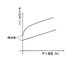
一般的には、図4に示すように、流動体にかかるずり速度とずり応力の二軸を取り、ずり速度を変化させたときのずり応力をプロットして流動曲線を描いたとき、ずり応力がはじめて零から立ち上がる応力が、降伏値とされている。これに対し、流動体の物性を測定する装置としては、振動式粘度計、回転式粘度計等が利用されている。振動式粘度計には、回転振動式粘度計と、音叉振動式粘度計がある。 In general, as shown in FIG. 4, when two axes of the shear rate and the shear stress applied to the fluid are taken, and the shear stress when the shear rate is changed is plotted, the shear stress is drawn. The stress that rises from zero for the first time is regarded as the yield value. On the other hand, as a device for measuring the physical properties of the fluid, a vibration viscometer, a rotary viscometer, or the like is used. The vibration type viscometer includes a rotary vibration type viscometer and a tuning fork vibration type viscometer.
回転振動式粘度計は、測定する流動体の試料に単一の振動子を挿入し、回転子を回転方向に共振させ、共振時の回転子の振幅の減衰を測定し、粘度に換算する(特許文献1)。 A rotational vibration viscometer inserts a single vibrator into a fluid sample to be measured, resonates the rotor in the rotational direction, measures the attenuation of the amplitude of the rotor at the time of resonance, and converts it to viscosity ( Patent Document 1).
音叉振動式粘度計は、試料に一対の振動子を挿入し、一対の振動子を逆位相で振動させ、振動子の振幅が一定となるように振動子の駆動電流を制御して、この駆動電流を粘度に換算する(特許文献2)。 A tuning-fork vibratory viscometer inserts a pair of vibrators into a sample, vibrates a pair of vibrators in opposite phases, and controls the drive current of the vibrators so that the amplitude of the vibrators is constant. The current is converted into viscosity (Patent Document 2).
回転式粘度計は、試料に回転子を挿入し、回転子の回転数を停止状態から上げ、回転数に対応するトルクを測定する(特許文献3)。 A rotary viscometer inserts a rotor into a sample, raises the rotational speed of the rotor from a stopped state, and measures torque corresponding to the rotational speed (Patent Document 3).
しかし、降伏値は、流動体が動きはじめる応力の限界値であるので、これを測定するには、流動体の組成を壊すことなく、微小な組成の変化を検知するよう外力を変化させなければならない。 However, since the yield value is the limit value of the stress at which the fluid begins to move, in order to measure this, the external force must be changed to detect minute changes in the composition without destroying the composition of the fluid. Don't be.
これに対し、回転振動式粘度計は、駆動部に圧電素子が利用されているため、振動子に与える振動周波数が高く(約1kHz)、試料に加わるストレスが大きいため、流動体の組成が乱されているおそれがある。また、その測定原理からも、試料に与える応力を直接制御することはできないため、降伏値を測定することは難しい。 On the other hand, the rotational vibration viscometer uses a piezoelectric element in the drive unit, so the vibration frequency applied to the vibrator is high (about 1 kHz) and the stress applied to the sample is large, so the composition of the fluid is disturbed. There is a risk that. Moreover, it is difficult to measure the yield value because the stress applied to the sample cannot be directly controlled from the measurement principle.
音叉振動式粘度計は、駆動周波数が低い(約30Hz)ことが特徴の一つであり、試料に加わるストレスが小さく、試料の組成を壊しがたいと言える。しかし、その測定原理は、振動子の振幅(ずり速度)が一定という条件下で駆動電流(ずり応力)を測定するのであって、試料に与える応力を制御することはできないため、降伏値を測定することは出来ない。 One of the characteristics of the tuning fork vibration type viscometer is that the drive frequency is low (about 30 Hz), the stress applied to the sample is small, and it can be said that the composition of the sample is difficult to break. However, the measurement principle is that the drive current (shear stress) is measured under the condition that the amplitude (shear rate) of the vibrator is constant, and the stress applied to the sample cannot be controlled, so the yield value is measured. I can't do it.
回転式粘度計は、回転子の回転数がずり速度に比例するとの考え方から、回転数(ずり速度)に対するトルク(ずり応力)を測定するので、トルクの測定点の回帰直線を求め、その切片を降伏値として測定するものもある(特に、特許文献3の段落0019)。しかし、回転式粘度計は、測定対象が低粘度や低ずり速度であると、回転子のトルクが試料に伝わりにくく、精度が悪いことが知られており、低ずり速度域にあらわれる降伏値も、正確な値が得られているか確かではない。 The rotational viscometer measures torque (shear stress) against the number of revolutions (shear speed) based on the idea that the number of revolutions of the rotor is proportional to the shear speed. Is measured as a yield value (particularly, paragraph 0019 of Patent Document 3). However, with a rotary viscometer, it is known that if the object to be measured is low viscosity or low shear rate, the torque of the rotor is difficult to be transmitted to the sample and the accuracy is poor, and the yield value that appears in the low shear rate range is also I'm not sure if the correct value is being obtained.
このように、従来の粘度計では、正確な降伏値は測定できないという問題があった。本発明は、従来技術の問題を解決するために、音叉振動式粘度計を利用して、精度の高い降伏値を得ることを提案することで、より実態に近い流動体の物性解明に貢献しようとするものである。 Thus, the conventional viscometer has a problem that an accurate yield value cannot be measured. In order to solve the problems of the prior art, the present invention proposes to obtain a yield value with high accuracy by using a tuning fork vibration viscometer, thereby contributing to the elucidation of the physical properties of the fluid closer to the actual situation. It is what.
前記目的を達成するために、本発明に係る音叉振動式粘度計では、流動体に挿入される一対の振動子と、前記振動子の振幅値を検出する変位センサと、前記振動子に電磁振動を加振する、電磁コイルを備えた電磁駆動部と、前記電磁コイルに流す駆動電流を、零から設置値まで増大又は設定値から零まで減少させる駆動電流制御手段と、前記駆動電流の値及びこれに対応する前記振幅値を記録する記憶手段と、前記振幅値の変局点を判断し、そのときの前記駆動電流値を降伏値とする降伏値測定手段と、を備えることを特徴とする。 In order to achieve the above object, in a tuning fork vibratory viscometer according to the present invention, a pair of vibrators inserted into a fluid, a displacement sensor for detecting an amplitude value of the vibrator, and an electromagnetic vibration in the vibrator. An electromagnetic drive unit having an electromagnetic coil, drive current control means for increasing or decreasing a drive current flowing through the electromagnetic coil from zero to a set value, and a value of the drive current and The storage means for recording the amplitude value corresponding to this, and the yield value measuring means for judging the inflection point of the amplitude value and using the drive current value at that time as the breakdown value .
また、本発明に係る降伏値の測定方法では、流動体に挿入される一対の振動子と、前記振動子の振幅値を検出する変位センサと、前記振動子に電磁振動を加振する、電磁コイルを備えた電磁駆動部と、前記電磁コイルに流す駆動電流を、零から設置値まで増大又は設定値から零まで減少させる駆動電流制御手段と、を備える音叉振動式粘度計を用いた降伏値の測定方法であって、前記電磁コイルに流す測定開始駆動電流値を決定する開始値設定ステップと、前記電磁コイルに流す測定停止駆動電流値を決定する停止値設定ステップと、前記駆動電流を変更させる駆動電流制御ステップと、振動子の振動開始から停止まで、前記駆動電流の値及び前記振幅値を記録する記録ステップと、前記振幅値の変局点を判断し、そのときの前記駆動電流値を降伏値として算出する降伏値測定ステップと、を備えることを特徴とする。 In the yield value measuring method according to the present invention, a pair of vibrators inserted into a fluid, a displacement sensor that detects an amplitude value of the vibrator, and an electromagnetic vibration that excites electromagnetic vibrations in the vibrator. Yield value using a tuning-fork vibration viscometer comprising: an electromagnetic drive unit including a coil; and drive current control means for increasing or decreasing a drive current flowing through the electromagnetic coil from zero to a set value. A start value setting step for determining a measurement start drive current value to be passed through the electromagnetic coil, a stop value setting step for determining a measurement stop drive current value to be passed through the electromagnetic coil, and changing the drive current A drive current control step, a recording step for recording the value of the drive current and the amplitude value from the start to stop of vibration of the vibrator, and an inflection point of the amplitude value are determined, and the drive current value at that time A yield value measuring step of calculating a yield value, characterized in that it comprises a.
好ましくは、本発明に係る音叉振動式粘度計では、前記降伏値測定手段で、前記降伏値は、前記振幅値の変局点と対応する駆動電流値である降伏駆動電流値と、前記電磁コイルの磁束密度と、前記電磁コイルのコイル長と、の積を、前記振動子のてこ比で除して得られる、振動子にかかるトルクである降伏駆動力に換算する。 Preferably, in the tuning fork vibration type viscometer according to the present invention, the yield value measuring means includes a breakdown drive current value that is a drive current value corresponding to an inflection point of the amplitude value, and the electromagnetic coil. The product of the magnetic flux density and the coil length of the electromagnetic coil is converted into a yield driving force, which is a torque applied to the vibrator, obtained by dividing the product by the lever ratio of the vibrator.
好ましくは、本発明に係る降伏値の測定方法では、前記降伏値測定ステップは、前記降伏値は、前記振幅値の変局点と対応する駆動電流値である降伏駆動電流値と、前記電磁コイルの磁束密度と、前記電磁コイルのコイル長と、の積を、前記振動子のてこ比で除して得られる、振動子にかかるトルクである降伏駆動力に換算する。 Preferably, in the yield value measuring method according to the present invention, in the yield value measuring step, the yield value is a drive current value corresponding to the inflection point of the amplitude value, and the electromagnetic coil. The product of the magnetic flux density and the coil length of the electromagnetic coil is converted into a yield driving force, which is a torque applied to the vibrator, obtained by dividing the product by the lever ratio of the vibrator.
好ましくは、本発明に係る降伏値の測定方法は、コンピュータプログラムで記載され実行される。 Preferably, the yield value measuring method according to the present invention is described and executed by a computer program.
本発明の音叉振動式粘度計によれば、一対の振動子を共振振動させる駆動電流を、零から設置値まで増大又は設定値から零まで減少させるように制御し、この駆動電流の変更に対する振動子の振幅の変化を検出し、振幅値の変局点に対応する駆動電流値を降伏値とするので、精度の高い降伏値を得ることができる。 According to the tuning fork vibration type viscometer of the present invention, the drive current for resonantly vibrating the pair of vibrators is controlled to increase from zero to the set value or decrease from the set value to zero, and the vibration with respect to the change in the drive current Since the change in the amplitude of the child is detected and the drive current value corresponding to the inflection point of the amplitude value is used as the breakdown value, a high-accuracy breakdown value can be obtained.
次に、本発明の好適な実施の形態について説明する。 Next, a preferred embodiment of the present invention will be described.
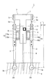
図1は、本発明に係る音叉振動式粘度計1の駆動機構部2の構成概略図である。音叉振動式粘度計1の本体及び駆動機構部2の構成は、従来の構成と同様であるため、適宜説明を簡略する。
FIG. 1 is a schematic configuration diagram of a
駆動機構部2の、符号3,3は、測定用容器(図示せず)に入れられた試料4中に挿入される一対の振動子であり、セラミック部材や金属部材等の薄肉平板状の板材から形成され、先端に円形状の拡大部が設けられている。この拡大部が、試料4との接液部3aとなる。
符号5,5は、一対の板バネであり、板バネ5,5に対し、振動子3,3の基端部が、接続部材6,6を介して固定されている。板バネ5の振動子接続側端部と反対の端部は、逆凸形状のフレーム7の左右凸部に固定されている。板バネ5の長手方向中央部には、薄肉部が形成されている。フレーム7は、図示しない粘度計1本体のスタンドにより支持されており、本体に設置のハンドル操作により、昇降及び前後移動可能に構成されている。これにより、一対の振動子3,3は、一定の深さでもって試料4に挿入され、厚み方向の中心軸が試料4中で同一平面上に位置するように配置される。フレーム7の下方凸部には、試料用温度センサ8、駆動機構部温度センサ9が設けられている。
符号10は電磁駆動部であり、振動子3と接続する接続部材6の中央部に固定されたフェライト磁石10aの一端部が、フレーム7の下方凸部側面に固定された電磁コイル10bの内側に挿入された、ムービングマグネット方式として構成されている。この電磁駆動部10により、板バネ5,5を一定の振動数で逆位相に強制的に共振振動させることで、振動子3,3が同様の振動をする。符号11は渦電流損検出非接触型の変位センサである。変位センサ11は、振動子3の振幅は振動子3と一体となっている板バネ5の振幅と同等であるとして、フレーム7に、板バネ5の振動子接続側端部と近接する位置に固定され、板バネ5の振幅値を検出する。
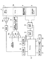
次に、図2は、本発明に係る音叉振動式粘度計の制御駆動系のブロック図である。 Next, FIG. 2 is a block diagram of a control drive system of the tuning-fork vibration type viscometer according to the present invention.
符号30a、30b、30cはアンプ、符号31は正弦波発生回路、符号32はV/I変換回路、符号33は整流器、符号34,41はA/D変換器、符号35は、CPU、ROM、RAM等を内蔵するマイコン、符号36は電圧変換回路、符号37は表示部、符号38はキースイッチ部、符号39はメモリ、符号41は入力選択部、である。後述で明らかとなるように、マイコン35が、駆動電流制御手段及び降伏値測定手段、メモリ39が記憶手段である。なお、A/D変換器34,41、電圧変換回路36等が適宜マイコン35に内蔵される構成も当然に想定される。
降伏値の測定を開始すると、例えば水晶振動子(図示せず)等の発振器で生成された30Hzの基準駆動信号が、アンプ30aで増幅され、正弦波発生回路31、V/I変換回路32を経て正弦波信号に変調されて、駆動電流が電磁コイル10bに流れる。これにより、電磁駆動部10で磁力が発生し、振動子3,3が逆位相の共振振動を開始する。これを受けた振動子3の振幅が変位センサ11により検出される。検出された振幅値Aの信号は、アンプ30cで増幅され、整流器33で整流され、A/D変換器34でデジタル信号となって、マイコン35に入力される。
When the measurement of the yield value is started, a 30 Hz reference drive signal generated by an oscillator such as a crystal resonator (not shown) is amplified by the
マイコン35は、PWM変調回路を有しており、電磁コイル10bに入力される駆動電流を後述の手順で制御するためのPWM信号を、電圧変換回路36に出力する。
The
マイコン35から電圧変換回路36を経て出力された信号は、アンプ30bで増幅され、正弦波発生回路31で基準駆動信号と合成される。合成によって変調された駆動信号が、V/I変換回路32を経て、駆動電流として電磁コイル10bに流れる。このPWM変調後の駆動電流値iは、予めROM等に記憶されているマイコン35から出力されるPWM信号との対応値として得られる。駆動電流値iと振幅値Aの測定値は、メモリ39に記録される。この手順が、降伏値測定終了まで繰り返される。
A signal output from the
また、試料用温度センサ8、駆動機構部温度センサ9からの信号は、マイコンからの入力選択信号にもとづいて、入力選択部40によって一定のタイミングで切換られ、A/D変換器41でデジタル信号となって、マイコン35に入力され、マイコンの入力選択信号によって、メモリ39の別の領域に記録される。試料用温度センサ8からの信号により算出された試料温度は、操作者の要求に応じて適宜表示部37等に出力される。また、駆動機構部温度センサ9からの信号により算出された駆動機構部の温度は、必要に応じ測定値の補正に使用される。
The signals from the
すなわち、従来の音叉振動式粘度計は、振動子3の振幅が一定となるように駆動電流を増減させ、駆動電流値iから粘度を算出するような制御系であったのに対し、本音叉振動式粘度計1は、駆動電流値iを設定に基づいて可変し、この駆動電流値iの変更による振動子3の振幅の変化を連続的に測定する制御系として構成されている。
That is, the conventional tuning fork vibratory viscometer is a control system in which the drive current is increased or decreased so that the amplitude of the
以下、駆動電流値iの制御手順及び降伏値の測定方法について、図3のフローチャートに基づき説明する。図3は本発明に係る降伏値測定のフローチャートである。 Hereinafter, the control procedure of the drive current value i and the method of measuring the breakdown value will be described based on the flowchart of FIG. FIG. 3 is a flowchart of yield value measurement according to the present invention.
まず、ステップS1で、振動子3を振動させるための駆動電流値iの初期状態、測定開始駆動電流値Isを設定する。駆動電流値iを増加させていく場合、駆動電流値iの初期状態はゼロ(Is=0)を設定する。駆動電流値iを減少させていく場合、駆動電流値iの所定の設定値(最大値)を設定する。ステップS1が、開始値設定ステップである。
First, in step S1, an initial state of a drive current value i for vibrating the
次に、ステップS2で、駆動電流値iを一定時間毎に変化させていくための変化の割合、駆動電流変化量Ic、単位測定時間Tcを設定する。これにより単位測定時間Tc経過毎に、駆動電流値iが駆動電流変化量Ic分、変化することになる。駆動電流値iを増加させていく場合、Icは正となる。駆動電流値iを減少させていく場合、Icは負となる。 Next, in step S2, a change rate, a drive current change amount Ic, and a unit measurement time Tc for changing the drive current value i at regular intervals are set. As a result, every time the unit measurement time Tc elapses, the drive current value i changes by the drive current change amount Ic. When the drive current value i is increased, Ic becomes positive. When the drive current value i is decreased, Ic becomes negative.
駆動電流変化量Icに従って、一定時間毎に駆動電流値iを変化させていき、所定の駆動電流に達すると測定を停止するが、ステップS3で、測定を停止するときの駆動電流値、測定停止駆動電流値Ieを設定する。ステップS3が、停止値設定ステップである。 The drive current value i is changed at regular intervals according to the drive current change amount Ic, and the measurement is stopped when the predetermined drive current is reached. In step S3, the drive current value when the measurement is stopped and the measurement stop A drive current value Ie is set. Step S3 is a stop value setting step.
ステップS1〜S3の設定は、基本的に操作者によってキースイッチ部38等を介して任意に行われる。但し、測定開始駆動電流値Is、駆動電流変化量Ic、単位測定時間Tc、測定停止駆動電流値Ieは、好適なパターンを予めマイコン35内のROMやメモリ39に格納しておいてもよい。この場合、操作者が駆動電流値iを増大させるか減少させるかのみ選択することで、開始値設定ステップおよび停止値設定ステップが行われる。
The setting of steps S1 to S3 is basically arbitrarily performed by the operator via the
次に、ステップS4で、操作者による測定開始の指示に従い、降伏値の測定を開始する。測定が開始されれば、ステップS5に進める。開始されない場合はステップS4に戻る。 Next, in step S4, according to the measurement start instruction from the operator, the measurement of the yield value is started. If the measurement is started, the process proceeds to step S5. If not started, the process returns to step S4.
ステップS5に進むと、マイコン35により基準駆動信号を変調し、駆動電流値iを測定開始駆動電流値Isにする。
In step S5, the reference drive signal is modulated by the
次に、ステップS6で、測定タイマtmをリセットする。測定タイマiは、マイコン35に内蔵されるカウンタ等で、駆動電流値iを変化させるタイミングを検出するために用いられるもので、一定時間毎に増加し更新されるものである。
Next, in step S6, the measurement timer tm is reset. The measurement timer i is a counter or the like built in the
次に、ステップS7で、変位センサ11で、駆動電流値iに対応した振動子3の振幅を測定し、そのときの駆動電流値i、測定した振幅値Aを、刻々連続的に、メモリ39に記録する。この駆動電流値i及び振幅値Aは、パーソナルコンピュータなどの外部機器に出力しても良い。ステップS7が、記録ステップである。
Next, in step S7, the
次に、ステップS8で、タイマtm が単位測定時間 Tc に達するか否かを判定する。単位測定時間 Tc に達する場合はステップS9に進める。達していない場合は、ステップS7に戻り振幅値Aの測定を継続する。 Next, in step S8, it is determined whether or not the timer tm reaches the unit measurement time Tc. If the unit measurement time Tc is reached, the process proceeds to step S9. If not, the process returns to step S7 and the measurement of the amplitude value A is continued.
ステップS9に進むと、ステップS1〜S3の設定に基づき、設定された駆動電流変化量 Ic に従い、駆動電流値iが(i=i+Ic)となるよう、マイコン35からPMW信号が出力され、駆動電流値iが変更される。ステップS9が、駆動電流制御ステップである。
In step S9, based on the settings in steps S1 to S3, the PMW signal is output from the
次に、ステップS10で、駆動電流値iが測定停止駆動電流値Ieに達したか否かを判定する。駆動電流値iが測定停止駆動電流値Ieに達した場合はステップS11に進める。達していない場合は、ステップS6に戻り測定を継続する。 Next, in step S10, it is determined whether or not the drive current value i has reached the measurement stop drive current value Ie. When the drive current value i reaches the measurement stop drive current value Ie, the process proceeds to step S11. If not, the process returns to step S6 and measurement is continued.
ステップS11に進むと、駆動電流値iが測定停止駆動電流値Ieに達しているので、測定を停止し、駆動電流値iをゼロにして、振動子3の振動を停止する。
In step S11, since the drive current value i has reached the measurement stop drive current value Ie, the measurement is stopped, the drive current value i is set to zero, and the vibration of the
次に、ステップS12で、刻々と連続的に記録された駆動電流値iと振幅値Aの関係で、マイコン35に内蔵されるCPUによって、振幅値Aの変局する点を判断し、そのときの駆動電流値iを降伏値(Iy:降伏駆動電流値)として求める。すなわち、ステップS12が、降伏値測定ステップである。なお、駆動電流は正弦波となるため、駆動電流値iの測定値は実効値とする。
Next, in step S12, a point where the amplitude value A is changed is determined by the CPU built in the
なお、振幅値Aの変局点の判断は、駆動電流を増加させていく場合は、振動子が振幅を開始した点、または一定以上の振幅となった点、駆動電流を減少させていく場合は、振動子が振動を停止した点、または一定以下の振幅となった点等とする。更に詳しく判断するためには、駆動電流(即ち、流動体に与える応力[τ]に相関)と、振動子の振幅(即ち、ずり速度[Ds]に相関)の比率(τ/Ds)から、粘度に相当する物理量(塑性粘度とする)を刻々と算出し、更に塑性粘度の変化の微分を行い、微分値の絶対値が最大となる点などから、変局点を判断するのが好ましい。 The inflection point of the amplitude value A is determined when the drive current is increased, when the vibrator starts the amplitude, or when the amplitude becomes a certain level or more, when the drive current is decreased. Is a point where the vibrator stops vibrating or a point where the amplitude becomes a certain level or less. In order to judge in more detail, from the ratio (τ / Ds) of the drive current (that is, correlated with the stress [τ] applied to the fluid) and the amplitude of the vibrator (that is, correlated with the shear rate [Ds]), It is preferable to calculate the physical quantity corresponding to the viscosity (referred to as plastic viscosity) every moment, further differentiate the change in plastic viscosity, and determine the inflection point from the point where the absolute value of the differential value becomes maximum.
なお、降伏値は、低ずり応力で確認されることを考慮すれば、降伏値を算出するステップS12は、測定終了を待って算出する必要はなく、ステップS7で、所定時間経過後(例えば10秒〜1分程度経過後)に、データの記録と同時平行して降伏値を算出してもよい。 In consideration of the fact that the yield value is confirmed with a low shear stress, the step S12 for calculating the yield value does not need to be calculated after completion of the measurement. The yield value may be calculated at the same time as the data recording after about 1 second to 1 minute has elapsed.
また、上記降伏値は、降伏駆動電流値Iy[mA]として算出されるが、ステップS12(或いはステップS7)で、振動子3にかかるトルクに換算した降伏駆動力Fyに換算しても良い。
The yield value is calculated as the yield drive current value Iy [mA], but may be converted to a yield drive force Fy converted to a torque applied to the
音叉振動式粘度計1では、振動子3が試料4中でサイン波での往復運動を行うため、試料4中で振動子3を動かすために必要な力(トルク)が働く。よって、振動子3の接液部3aの中心3oにおける駆動力Fを考えると、電磁駆動部10で発生する力F1を、振動子3の支点となる板バネ5の最薄肉部5aを基準とし、電磁駆動部10の上下方向中心までの距離d1と振動子接液部中心3oまでの距離d2の比(てこ比)αで除すことで求められる。電磁駆動部10で発生する力F1は、電磁コイル10bの磁束密度B、電磁コイル10bに流れる駆動電流i及び電磁コイル10bのコイル長Lの積から求められる。てこ比α、磁束密度B、コイル長Lは、装置構成から既知の値となる。ここで、駆動電流iに、降伏駆動電流値Iyを用いれば、式 Fy=BIyL/ α で、トルクに換算した降伏駆動力Fy[N]が得られる。さらに、振動子の接液面積(接液部3aの面積)で除して、単位系を[Pa]としてもよい。
In the tuning
本実施例によれば、本音叉振動式粘度計1は、一対の振動子3を共振振動させる駆動電流を、零から設置値まで増大又は設定値から零まで減少させるように制御し、この駆動電流値iの変更に対する振動子3の振幅値Aの変化を検出し、振幅値の変局点に対応する駆動電流値iを降伏値とするので、精度の高い降伏値を得ることができる。
According to the present embodiment, the tuning
すなわち、本音叉振動式粘度計1は、振動子3,3の共振を利用して、振動子3を微小な駆動力(駆動電流)で駆動かつ駆動電流を微小範囲で可変させることができるので、試料4に与えるストレスが小さく、試料4の組成変化が生じ難いから、特に低エネルギー下で確認される降伏値を、他の粘度計の測定値よりも信頼性高く正確に捉えることができる。
That is, the tuning fork
また、音叉振動式粘度計1は、駆動力(駆動電流)を直接制御し、駆動電流値iの変更に対する振幅値Aの変化を連続的な状態変化として測定することができるため、降伏値だけでなく、同測定中に流動体のレオロジー性(ニュートン、非ニュートン性等)も容易に求められる。
Further, the tuning fork
1…音叉振動式粘度計、2…駆動機構部、 3…振動子、 4…試料、 5… 板バネ、 10…電磁駆動部、 10a…フェライト磁石、10b…電磁コイル、 11…変位センサ、 30a、30b、30c…アンプ、 31… 正弦波発生回路、 32…V/I変換器、 33…整流器、 34…A/D変換器
35…マイコン、 36…電圧変換器、 37…表示部、 38…キースイッチ部、 39…メモリ、 40…入力選択部、 41…A/D変換器
DESCRIPTION OF
Claims (5)
前記振動子の振幅値を検出する変位センサと、
前記振動子に電磁振動を加振する、電磁コイルを備えた電磁駆動部と、
前記電磁コイルに流す駆動電流を、零から設置値まで増大又は設定値から零まで減少させる駆動電流制御手段と、
前記駆動電流の値及びこれに対応する前記振幅値を記録する記憶手段と、
前記振幅値の変局点を判断し、そのときの前記駆動電流値を降伏値とする降伏値測定手段と、
を備えることを特徴とする音叉振動式粘度計。 A pair of transducers inserted into the fluid;
A displacement sensor for detecting an amplitude value of the vibrator;
An electromagnetic drive unit including an electromagnetic coil for exciting electromagnetic vibration in the vibrator;
Drive current control means for increasing the drive current flowing through the electromagnetic coil from zero to the set value or decreasing from the set value to zero;
Storage means for recording the value of the drive current and the amplitude value corresponding thereto;
Determining the inflection point of the amplitude value, and a yield value measuring means having the drive current value at that time as a breakdown value;
A tuning fork vibration viscometer characterized by comprising:
前記振動子の振幅値を検出する変位センサと、
前記振動子に電磁振動を加振する、電磁コイルを備えた電磁駆動部と、
前記電磁コイルに流す駆動電流を、零から設置値まで増大又は設定値から零まで減少させる駆動電流制御手段と、を備える音叉振動式粘度計を用いた降伏値の測定方法であって、
前記電磁コイルに流す測定開始駆動電流値を決定する開始値設定ステップと、
前記電磁コイルに流す測定停止駆動電流値を決定する停止値設定ステップと、
前記駆動電流を変更させる駆動電流制御ステップと、
振動子の振動開始から停止まで、前記駆動電流の値及び前記振幅値を記録する記録ステップと、
前記振幅値の変局点を判断し、そのときの前記駆動電流値を降伏値として算出する降伏値測定ステップと、
を備えることを特徴とする降伏値の測定方法。 A pair of transducers inserted into the fluid;
A displacement sensor for detecting an amplitude value of the vibrator;
An electromagnetic drive unit including an electromagnetic coil for exciting electromagnetic vibration in the vibrator;
A driving current flowing through the electromagnetic coil, a driving current control means for increasing from zero to an installation value or decreasing from a setting value to zero, and a method for measuring a yield value using a tuning fork vibrating viscometer,
A start value setting step for determining a measurement start drive current value to be passed through the electromagnetic coil;
A stop value setting step for determining a measurement stop drive current value to be passed through the electromagnetic coil;
A drive current control step for changing the drive current;
A recording step of recording the value of the drive current and the amplitude value from the start to stop of vibration of the vibrator;
A yield value measuring step of determining an inflection point of the amplitude value and calculating the drive current value at that time as a yield value;
A method of measuring a yield value, comprising:
Priority Applications (1)
| Application Number | Priority Date | Filing Date | Title |
|---|---|---|---|
| JP2014067681A JP2015190829A (en) | 2014-03-28 | 2014-03-28 | Method, program, and device for determining yield value of fluid |
Applications Claiming Priority (1)
| Application Number | Priority Date | Filing Date | Title |
|---|---|---|---|
| JP2014067681A JP2015190829A (en) | 2014-03-28 | 2014-03-28 | Method, program, and device for determining yield value of fluid |
Publications (1)
| Publication Number | Publication Date |
|---|---|
| JP2015190829A true JP2015190829A (en) | 2015-11-02 |
Family
ID=54425432
Family Applications (1)
| Application Number | Title | Priority Date | Filing Date |
|---|---|---|---|
| JP2014067681A Pending JP2015190829A (en) | 2014-03-28 | 2014-03-28 | Method, program, and device for determining yield value of fluid |
Country Status (1)
| Country | Link |
|---|---|
| JP (1) | JP2015190829A (en) |
Cited By (3)
| Publication number | Priority date | Publication date | Assignee | Title |
|---|---|---|---|---|
| WO2018197900A1 (en) * | 2017-04-27 | 2018-11-01 | Hydramotion Limited | The measurement of properties of vibrated yield stress fluids |
| CN108827831A (en) * | 2018-06-07 | 2018-11-16 | 深圳市鸿曙科技有限公司 | Oscillatory type viscosity apparatus and its Detection Method of Liquid Viscosity |
| CN110361295A (en) * | 2019-07-24 | 2019-10-22 | 东北石油大学 | A kind of w/o type waxy crude oil emulsion yield point determines method |
Citations (4)
| Publication number | Priority date | Publication date | Assignee | Title |
|---|---|---|---|---|
| JPH01132931A (en) * | 1987-11-18 | 1989-05-25 | Chichibu Cement Co Ltd | Method for analyzing physical properties of sample by viscometer |
| JPH08128940A (en) * | 1994-10-31 | 1996-05-21 | Kinugawa Rubber Ind Co Ltd | Viscosity measuring method for electroviscous fluid |
| JP2000283907A (en) * | 1999-03-30 | 2000-10-13 | A & D Co Ltd | Vibrator viscometer |
| US20080060423A1 (en) * | 2006-04-29 | 2008-03-13 | Wen-Chen Jau | Measurements of yield stress and plastic viscosity of cement-based materials via concrete rheometer |
-
2014
- 2014-03-28 JP JP2014067681A patent/JP2015190829A/en active Pending
Patent Citations (4)
| Publication number | Priority date | Publication date | Assignee | Title |
|---|---|---|---|---|
| JPH01132931A (en) * | 1987-11-18 | 1989-05-25 | Chichibu Cement Co Ltd | Method for analyzing physical properties of sample by viscometer |
| JPH08128940A (en) * | 1994-10-31 | 1996-05-21 | Kinugawa Rubber Ind Co Ltd | Viscosity measuring method for electroviscous fluid |
| JP2000283907A (en) * | 1999-03-30 | 2000-10-13 | A & D Co Ltd | Vibrator viscometer |
| US20080060423A1 (en) * | 2006-04-29 | 2008-03-13 | Wen-Chen Jau | Measurements of yield stress and plastic viscosity of cement-based materials via concrete rheometer |
Cited By (10)
| Publication number | Priority date | Publication date | Assignee | Title |
|---|---|---|---|---|
| WO2018197900A1 (en) * | 2017-04-27 | 2018-11-01 | Hydramotion Limited | The measurement of properties of vibrated yield stress fluids |
| CN110914663A (en) * | 2017-04-27 | 2020-03-24 | 海德拉运动有限公司 | Measurement of properties of vibrating yield stress fluids |
| JP2020522679A (en) * | 2017-04-27 | 2020-07-30 | ハイドラモーション リミテッド | Flow Yield Stress Measurement of Fluid Properties |
| JP2020522680A (en) * | 2017-04-27 | 2020-07-30 | ハイドラモーション リミテッド | Measuring the properties of an oscillated yield stress fluid |
| JP7244182B2 (en) | 2017-04-27 | 2023-03-22 | ハイドラモーション リミテッド | Measurement of flow yield stress fluid properties |
| JP7244183B2 (en) | 2017-04-27 | 2023-03-22 | ハイドラモーション リミテッド | Measurement of properties of oscillated yield stress fluids |
| CN110914663B (en) * | 2017-04-27 | 2023-06-13 | 海德拉运动有限公司 | Measurement of properties of vibrating yield stress fluid |
| CN108827831A (en) * | 2018-06-07 | 2018-11-16 | 深圳市鸿曙科技有限公司 | Oscillatory type viscosity apparatus and its Detection Method of Liquid Viscosity |
| CN110361295A (en) * | 2019-07-24 | 2019-10-22 | 东北石油大学 | A kind of w/o type waxy crude oil emulsion yield point determines method |
| CN110361295B (en) * | 2019-07-24 | 2022-06-21 | 东北石油大学 | Method for determining yield point of W/O type wax-containing crude oil emulsion |
Similar Documents
| Publication | Publication Date | Title |
|---|---|---|
| CN107278267B (en) | Vibration sensor | |
| CN109477751B (en) | Electronic vibration sensor | |
| WO2014049698A1 (en) | Method and device for measuring fluid body physical properties | |
| US5323638A (en) | Sensor apparatus | |
| US7520162B2 (en) | Vibration meter and method of measuring a viscosity of a fluid | |
| JPH01132931A (en) | Method for analyzing physical properties of sample by viscometer | |
| WO2013111608A1 (en) | Viscoelasticity measurement method and viscoelasticity measurement device | |
| WO2014087538A1 (en) | Ultrasonic fatigue testing device and ultrasonic fatigue testing method | |
| JP2015190829A (en) | Method, program, and device for determining yield value of fluid | |
| JP6016934B2 (en) | Method, program and apparatus for determining fluid shear rate | |
| JP3348162B2 (en) | Liquid viscosity and viscoelasticity measuring methods and viscoelasticity measuring devices | |
| JP2006214842A (en) | Liquid physical property value measuring instrument and liquid physical property value measuring method | |
| JP5674159B2 (en) | Viscosity measuring method and viscosity measuring apparatus | |
| JP2011027654A (en) | Calibration parameter determination method and density calculation method of vibration type densitometer | |
| JP6169092B2 (en) | Method, program and apparatus for evaluating reach distance of shear rate acting on fluid | |
| JP6345193B2 (en) | Method and apparatus for measuring physical properties of fluid | |
| JP2534173B2 (en) | Fluid viscosity measuring method and measuring apparatus | |
| JP2015132570A (en) | Viscosity measurement device and viscosity measurement method | |
| JPH0121452B2 (en) | ||
| KR102011569B1 (en) | Device for measuring viscosity of minute volume liquids and method thereof | |
| CN104950142A (en) | Method for measuring vibration characteristic of cantilever and device for measuring vibration characteristic of cantilever | |
| JP7352329B2 (en) | Viscoelasticity measurement method and viscoelasticity measurement device | |
| US20230236103A1 (en) | Method and apparatus for calculating a vibratory meter q | |
| WO2015029196A1 (en) | Method and device for finding shear rate of fluid by vibration-type viscometer | |
| JP2004361300A (en) | Viscometer |
Legal Events
| Date | Code | Title | Description |
|---|---|---|---|
| A621 | Written request for application examination |
Free format text: JAPANESE INTERMEDIATE CODE: A621 Effective date: 20170303 |
|
| A977 | Report on retrieval |
Free format text: JAPANESE INTERMEDIATE CODE: A971007 Effective date: 20180221 |
|
| A131 | Notification of reasons for refusal |
Free format text: JAPANESE INTERMEDIATE CODE: A131 Effective date: 20180228 |
|
| A02 | Decision of refusal |
Free format text: JAPANESE INTERMEDIATE CODE: A02 Effective date: 20180905 |