WO2015029196A1 - Method and device for finding shear rate of fluid by vibration-type viscometer - Google Patents
Method and device for finding shear rate of fluid by vibration-type viscometer Download PDFInfo
- Publication number
- WO2015029196A1 WO2015029196A1 PCT/JP2013/073202 JP2013073202W WO2015029196A1 WO 2015029196 A1 WO2015029196 A1 WO 2015029196A1 JP 2013073202 W JP2013073202 W JP 2013073202W WO 2015029196 A1 WO2015029196 A1 WO 2015029196A1
- Authority
- WO
- WIPO (PCT)
- Prior art keywords
- shear rate
- fluid
- vibrator
- amplitude
- effective value
- Prior art date
Links
Images


Classifications
-
- G—PHYSICS
- G01—MEASURING; TESTING
- G01N—INVESTIGATING OR ANALYSING MATERIALS BY DETERMINING THEIR CHEMICAL OR PHYSICAL PROPERTIES
- G01N11/00—Investigating flow properties of materials, e.g. viscosity, plasticity; Analysing materials by determining flow properties
- G01N11/10—Investigating flow properties of materials, e.g. viscosity, plasticity; Analysing materials by determining flow properties by moving a body within the material
- G01N11/16—Investigating flow properties of materials, e.g. viscosity, plasticity; Analysing materials by determining flow properties by moving a body within the material by measuring damping effect upon oscillatory body
Definitions
- the present invention relates to a method and apparatus for determining a shear rate applied to a fluid in a vibratory viscometer.
- the viscosity ⁇ which is an important element for evaluating the physical properties of the fluid, is obtained by arranging two parallel flat plates P and Q in the x direction in a fluid space by orthogonal coordinates.
- a unit area on a plane parallel to the flow direction between the flat plates PQ generated due to the difference between the shear rate D, which is a speed gradient when the flat plate Q is moved at a constant speed in the x direction, and P is fixed. It is known that it is expressed by the equation (1) using a shear stress S that is a frictional force acting on a hit.
- the behavior of the fluid changes when the shear rate D is changed. Therefore, the measurement of the shear rate is indispensable in designing the physical properties of the fluid. The value you want to get.
- a vibratory viscometer is used as one of the devices for evaluating the physical properties of the fluid.
- the tuning fork vibration type viscometer immerses two vibrators in a fluid, resonates like a tuning fork, and drives a pair of vibrators by electromagnetic force generated by a combination of a magnetic circuit and an electromagnetic coil.
- the viscosity is measured by utilizing the fact that there is a correlation between the driving current and the sample viscosity (Patent Document 1).
- a rotational vibration (or torsional vibration) viscometer measures or constants the torque required to resonate one vibrator immersed in a fluid in the rotational direction and maintain a constant amplitude.
- the viscosity of the fluid sample liquid is measured by measuring the amplitude while maintaining the torque (Non-Patent Document 1).
- the vibrator reciprocates in the fluid, so the shear rate changes with time, and the shear rate applied to the fluid remains constant with time. Therefore, the vibration type is recognized as a measurement method and apparatus that cannot determine the shear rate.
- the present invention proposes a method for determining the shear rate applied to a fluid in a vibratory viscometer, and provides a vibratory viscometer that can determine the shear rate. is there.
- a pair of thin vibrators immersed in the fluid are vibrated by an electromagnetic drive unit having a coil, and the vibrator
- the shear rate generated in the fluid is obtained in a tuning-fork vibration viscometer that measures the viscosity of the fluid by passing a drive current through the coil so that the amplitude of the fluid becomes a set amplitude value.
- a shear rate D which acts on the fluid when the vibrator vibrates the wetted surface parallel direction about its wetted surface center, a sine curve, 1 / ⁇ maximum shear rate D 0 2 is obtained as the effective value D ′ of the shear rate, and the effective value D ′ of the shear rate is handled as the shear rate acting on the fluid at that time.
- a pair of thin vibrators immersed in a fluid is vibrated by an electromagnetic drive unit provided with a coil, and the amplitude of the vibrator becomes a set amplitude value.
- a tuning fork vibratory viscometer that measures the viscosity of a fluid by passing a drive current through a coil and measuring the drive current, and the vibrator vibrates in a direction parallel to the liquid contact surface around the liquid contact surface center.
- the shear rate D sometimes acting on the fluid is a sine curve, and 1 / ⁇ 2 of the maximum shear rate D 0 is obtained as the effective value D ′ of the shear rate, and the effective value D ′ of the shear rate is then calculated as the fluid. It is characterized by comprising a shearing speed determining means that handles the shearing speed acting on the
- the shear rate generated in the fluid it is necessary to drive one resonator immersed in the fluid to resonate in the rotational direction and maintain a constant amplitude.
- a rotational vibration viscometer that measures the viscosity of a fluid by measuring the torque or maintaining a constant torque and measuring the amplitude
- the shear speed generated in the fluid is obtained, and the vibrator has a rotational axis
- the shear rate D acting on the fluid when rotating and oscillating periodically at the center is a sine curve, and 1 / ⁇ 2 of the maximum shear rate D 0 is obtained as the effective value D ′ of the shear rate, and the effective value of the shear rate is obtained.
- D ′ is treated as the shear rate acting on the fluid at that time.
- the vibrator in the vibration type viscometer continuously reciprocates sinusoidally, and in the tuning fork vibration type, the vibrator is parallel to the liquid contact surface around the liquid contact center.
- Sine curve D D 0 ⁇ sin ⁇ t
- D 0 the maximum shear rate
- ⁇ the angular velocity of the vibrator
- t the time
- FIG. 1 is a configuration diagram of a tuning-fork vibration viscometer according to the present invention, and is a schematic configuration diagram of a drive mechanism unit 10 in a viscometer body.
- the detailed configuration of the viscometer body and the drive mechanism 10 is described in International Patent Application No. 2012/074654.
- reference numerals 1 and 1 are a pair of thin vibrators immersed in the fluid sample liquid 9, which are formed from a thin flat plate material such as a ceramic member or a metal member, and have a circular shape at the tip. An enlarged portion is provided. This enlarged portion becomes the liquid contact surface 1 a with the sample liquid 9.
- Numeral 7 is a container filled with the sample liquid 9, and numeral 3 is a temperature sensor.
- Reference numerals 4 and 4 are leaf springs having the vibrators 1 and 1 fixed at the tip, and reference numeral 8 is a central support member to which the leaf springs 4 and 4 are fixed.
- the vibrators 1 and 1 are the sample liquid in the container 7. 9 is configured to be immersed in a certain depth.
- Reference numeral 2b denotes an electromagnetic coil
- reference numeral 2a denotes a neodymium magnet
- the vibrators 1 and 1 provided at the tips of the leaf springs 4 and 4 by a moving magnet type electromagnetic drive unit 2 including the electromagnetic coil 2b and the neodymium magnet 2a. Is configured to vibrate with a set amplitude value.
- Reference numeral 5 denotes an eddy current loss detection non-contact type displacement sensor, which measures the amplitude values of the vibrators 1 and 1.
- FIG. 2 is a block diagram of the control drive system of the tuning-fork vibration type viscometer according to the present invention.
- Reference numeral 12 is a PWM modulation circuit
- reference numeral 13 is a sine wave generation circuit
- reference numeral 14 is a comparator
- reference numeral 15 is a controller
- reference numeral 16 is an I / V converter
- reference numerals 17 and 19 are A / D converters
- reference numeral 18 is An arithmetic processing unit.
- a drive signal is output from the arithmetic processing unit 18 so that the vibrators 1 and 1 immersed in the sample liquid 9 vibrate with a set amplitude value, and the drive current generated via the sine wave generation circuit 13 is generated.
- the electromagnetic coil 2 b of the electromagnetic drive unit 2 is energized and applied to the leaf springs 4 and 4. As a result, the vibrators 1 and 1 vibrate in opposite phases to form a resonance state.
- the amplitude values of the vibrators 1 and 1 are detected by the displacement sensor 5, and the detected amplitude value signal is compared with the set amplitude value by the comparator 14, and the vibrators 1 and 1 vibrate at the set amplitude value.
- a signal is output from the controller 15 and feedback control is performed.
- the drive current I energized to the electromagnetic coil 2b at that time is detected. Then, this drive current I is input to the arithmetic processing unit 18 via the I / V converter 16 and the A / D converter 17, and the viscosity of the sample liquid 9 is calculated.
- the viscosity calculation process is described in Japanese Published Patent Publication No. 5-149861.
- An input signal of the temperature sensor 3 is input to the arithmetic processing unit 18 via the temperature A / D converter 19.
- a PWM modulation circuit 12 is connected between the arithmetic processing unit 18 and the comparator 14, and the amplitude value input to the comparator 14 is set by performing pulse width modulation according to a command from the arithmetic processing unit 18.
- the amplitude value is arbitrarily changed, the amplitude of the vibrators 1 and 1 is changed during measurement, and the shear rate generated in the sample liquid 9 is changed.
- the arithmetic processing unit 18 is connected to a memory 21, a display unit 22, a key switch unit 23 (all not shown), and the user can set measurement conditions from the key switch unit 23.
- measurement conditions include measurement time and amplitude change settings (input of lower and upper limit values of the amplitude and determination of the amount of change in the amplitude timetable, whether to increase, decrease, or reciprocate the amplitude), etc. It is. Details of this are described in International Patent Application No. 2012/074654.
- the vibrator 1 periodically reciprocates around the center 1o of the liquid contact surface 1a in a direction parallel to the liquid contact surface 1a (X direction in FIG. 1). That is, the shear rate applied to the sample liquid 9 is zero when the displacement of the vibrator 1 is maximum, and the shear speed applied to the sample liquid 9 is maximum when the displacement of the vibrator 1 is zero. That is, the shear rate D applied to the sample liquid 9 by the vibration of the vibrator 1 is represented by a sine curve as shown in FIG. 3A and can be expressed by the equation (2).
- D 0 is the maximum shear rate
- ⁇ is the angular velocity of the vibrator
- t is the time.
- f frequency of the vibrator
- T vibration period of the vibrator.
- Equation (5) the relationship between the maximum value of the shear rate and the effective value D ′ of the shear rate is expressed by Equation (5).
- B magnetic flux density of the coil
- I 0 maximum current value flowing through the coil
- L coil length
- ⁇ leverage ratio of the vibrator
- ⁇ viscosity of the sample liquid
- A wetted area of the vibrator is there.
- Driving force F in the wetted surface center 1o of the vibrator 1 a force F 1 generated by the electromagnetic drive unit 2, with respect to the vertical center of the thinnest portion 4a of the leaf spring 4 as a supporting point of the vibrator 1, It is obtained by dividing by the ratio (leverage ratio) ⁇ of the distance d1 to the center in the vertical direction of the electromagnetic drive part 2 and the distance d2 to the liquid contact part center 1o of the vibrator (see FIG. 1).
- the shear stress S generated between the sample liquid 9 and the vibrator 1 is obtained. Can be requested. Therefore, if the viscosity ⁇ of the sample liquid 9 can be measured from the equation (1), the maximum shear rate D 0 can be obtained from the equation (6) with the maximum current value I 0 flowing through the coil 22.
- the magnetic flux density B, the coil length L, and the liquid contact area A are known values from the apparatus configuration.
- the maximum current value I 0 is determined by measuring with the set amplitude.
- the effective value D ′ of the shear rate is calculated by the arithmetic processing unit 18 (shear rate determining means).
- FIG. 4 is a graph showing the shear rate at each viscosity value as an effective value D ′ in the tuning-fork vibration viscometer according to the present invention.
- the horizontal axis represents the amplitude [mm] of the vibrator 1 and the vertical axis represents the viscosity value [mPa ⁇ s].
- the liquid contact area A of the tuning fork vibration type viscometer used for the measurement is 0.000304 [mm]
- the leverage ⁇ is 3.81
- the magnetic flux density B of the coil 22 is 0.308 [Web / m 2 ]
- the coil length L Was 4 [m].
- the maximum current value I 0 is a variable measured by the sample.
- Sample liquid 9 was 45 ml each of ion-exchanged water and a standard solution for viscosity calibration (JS20, JS200, JS2000, JS14000) defined in JIS Z8809 (under constant conditions at 25 ° C.).
- the measurement conditions were as follows: each fluid, measurement time 11 minutes, amplitude lower limit value 0.2 mm, upper limit value 1.2 mm, amplitude timetable change ⁇ 0.2 mm / min, amplitude decreased and then reciprocated.
- the viscosity (25 [° C.]) of each fluid is known (conforms to JIS Z8803), measurement was performed by inputting a value.
- the value of the effective value D ′ [1 / s] of the shear rate obtained as a result is shown in a white frame.
- FIG. 4 shows that even if the same amplitude is applied, the shear rate (effective value D ′) varies depending on the viscosity value.
- the vibrator 1 in the tuning fork vibration type viscometer reciprocally moves in a sinusoidal manner
- the vibrator 1 is in contact with the liquid contact surface centering on the liquid contact surface center 1o.
- the shear rate can be determined, and the shear rate can be handled quantitatively.
- the present invention can be applied not only to a tuning fork vibration type viscometer but also to a rotational vibration type viscometer.
- a rotational vibration (or torsional vibration) viscometer resonates a cylindrical vibrator immersed in a fluid in the direction of rotation, and generates the torque necessary for the vibrator to maintain a constant amplitude.
- This is a device that measures the viscosity of a fluid sample liquid by measuring or maintaining a constant torque and measuring the amplitude.
- the vibrator rotates and vibrates periodically around the rotation axis. (The node is reciprocally oscillated periodically in a clockwise / counterclockwise direction).
- the shear rate applied to the sample liquid by the rotational vibration of the vibrator of the rotational vibration type viscometer can be expressed by a sinusoidal equation (2) as in the tuning fork vibration type viscometer, the expressions (3) to (4) Therefore, also in the rotational vibration viscometer, the shear rate can be expressed by an effective value by the equation (5).
Abstract
Provided is a method for using a vibration-type viscometer to determine the shear rate applied to a fluid. Focusing on the continuous sinusoidal reciprocating motion of an oscillator (1) of a tuning fork vibration-type viscometer, the present invention expresses as a sine curve the shear rate that acts on a fluid (9) when the oscillator (1) moves in a reciprocating manner around a fluid-contacting surface center (1o) thereof in a direction parallel to a fluid-contacting surface (1a), and having captured the shear rate as the root mean square (D'=D0/√2) of the shear rate, can determine the shear rate and quantitatively manage the shear rate even using the vibration-type viscometer.
Description
本発明は、振動式粘度計において流動体に加わるずり速度を決定する方法及びその装置に関する。
The present invention relates to a method and apparatus for determining a shear rate applied to a fluid in a vibratory viscometer.
流動体の物性を評価するのに重要な要素である粘度ηは、図5に示すように、直交座標による流体空間に、x方向に二枚の平行な平板Pと平板Qを配置し、平板Pを固定し、平板Qをx方向に一定速度で動かした場合の速度勾配であるずり速度Dと、この速度の差のために発生する、平板PQ間の流れ方向に平行な平面に単位面積当りに働く摩擦力であるずり応力Sと、を用いて、式(1)で表されることが知られている。
As shown in FIG. 5, the viscosity η, which is an important element for evaluating the physical properties of the fluid, is obtained by arranging two parallel flat plates P and Q in the x direction in a fluid space by orthogonal coordinates. A unit area on a plane parallel to the flow direction between the flat plates PQ generated due to the difference between the shear rate D, which is a speed gradient when the flat plate Q is moved at a constant speed in the x direction, and P is fixed. It is known that it is expressed by the equation (1) using a shear stress S that is a frictional force acting on a hit.

ここで、特に、非ニュートン流体では、ずり速度Dを変化させた時の流動体の振舞いが変わるため、その流動体の物性設計上、ずり速度の測定が不可欠であり、粘度の測定に併せて取得したい値となる。
Here, especially in a non-Newtonian fluid, the behavior of the fluid changes when the shear rate D is changed. Therefore, the measurement of the shear rate is indispensable in designing the physical properties of the fluid. The value you want to get.
これに対し、流動体の物性を評価する装置の一つとして、振動式粘度計が利用されている。このうち、音叉振動式粘度計は、2つの振動子を流動体に浸し、音叉同様に共振させ、磁気回路と電磁コイルの組み合わせにより発生する電磁力により一対の振動子を駆動し、その際の駆動電流と試料粘度に相関関係があることを利用して、粘度を測定している(特許文献1)。回転振動式(又は捻り振動式)粘度計は、流動体中に浸漬した一の振動子を回転方向に共振させ、該振動子が一定の振幅を維持するのに必要となるトルクを測定又は一定のトルクを維持し振幅を測定して、流動体のサンプル液の粘度を測定している(非特許文献1)。
On the other hand, a vibratory viscometer is used as one of the devices for evaluating the physical properties of the fluid. Among them, the tuning fork vibration type viscometer immerses two vibrators in a fluid, resonates like a tuning fork, and drives a pair of vibrators by electromagnetic force generated by a combination of a magnetic circuit and an electromagnetic coil. The viscosity is measured by utilizing the fact that there is a correlation between the driving current and the sample viscosity (Patent Document 1). A rotational vibration (or torsional vibration) viscometer measures or constants the torque required to resonate one vibrator immersed in a fluid in the rotational direction and maintain a constant amplitude. The viscosity of the fluid sample liquid is measured by measuring the amplitude while maintaining the torque (Non-Patent Document 1).
しかし、振動式粘度計では、流動体中を振動子が往復運動するので、時間変化に対して刻々とずり速度が変化しており、流動体に加わるずり速度が時間変化に対して一定値とならないため、振動式は、ずり速度を決定することができない測定方法・装置として認識されている。
However, in a vibratory viscometer, the vibrator reciprocates in the fluid, so the shear rate changes with time, and the shear rate applied to the fluid remains constant with time. Therefore, the vibration type is recognized as a measurement method and apparatus that cannot determine the shear rate.
本発明は、従来技術の問題を解決するために、振動式粘度計において、流動体に加わるずり速度を決定する方法を提案し、ずり速度を求めることのできる振動式粘度計を提供するものである。
In order to solve the problems of the prior art, the present invention proposes a method for determining the shear rate applied to a fluid in a vibratory viscometer, and provides a vibratory viscometer that can determine the shear rate. is there.
前記目的を達成するために、本発明における流動体に発生するずり速度を求める方法では、流動体中に浸漬した一対の薄振動子を、コイルを備えた電磁駆動部によって振動させ、前記振動子の振幅が設定された振幅値となるように前記コイルに駆動電流を流し、前記駆動電流を測定して流動体の粘度を測定する音叉振動式粘度計における、流動体に発生するずり速度を求める方法であって、振動子がその接液面中心を中心に接液面と平行方向に振動するときに流動体に作用するずり速度Dを、正弦曲線とし、最大ずり速度D0の1/√2をずり速度の実効値D´として求め、ずり速度の実効値D´を、そのとき流動体に作用しているずり速度として扱うことを特徴とする。
In order to achieve the above object, in the method for determining the shear rate generated in the fluid in the present invention, a pair of thin vibrators immersed in the fluid are vibrated by an electromagnetic drive unit having a coil, and the vibrator The shear rate generated in the fluid is obtained in a tuning-fork vibration viscometer that measures the viscosity of the fluid by passing a drive current through the coil so that the amplitude of the fluid becomes a set amplitude value. a method, a shear rate D which acts on the fluid when the vibrator vibrates the wetted surface parallel direction about its wetted surface center, a sine curve, 1 / √ maximum shear rate D 0 2 is obtained as the effective value D ′ of the shear rate, and the effective value D ′ of the shear rate is handled as the shear rate acting on the fluid at that time.
本発明における音叉振動式粘度計では、流動体中に浸漬した一対の薄振動子を、コイルを備えた電磁駆動部によって振動させ、前記振動子の振幅が設定された振幅値となるように前記コイルに駆動電流を流し、前記駆動電流を測定して流動体の粘度を測定する音叉振動式粘度計であって、振動子がその接液面中心を中心に接液面と平行方向に振動するときに流動体に作用するずり速度Dを、正弦曲線とし、最大ずり速度D0の1/√2をずり速度の実効値D´として求め、ずり速度の実効値D´を、そのとき流動体に作用しているずり速度として扱う、ずり速度決定手段を備えることを特徴とする。
In the tuning fork vibration type viscometer according to the present invention, a pair of thin vibrators immersed in a fluid is vibrated by an electromagnetic drive unit provided with a coil, and the amplitude of the vibrator becomes a set amplitude value. A tuning fork vibratory viscometer that measures the viscosity of a fluid by passing a drive current through a coil and measuring the drive current, and the vibrator vibrates in a direction parallel to the liquid contact surface around the liquid contact surface center. The shear rate D sometimes acting on the fluid is a sine curve, and 1 / √2 of the maximum shear rate D 0 is obtained as the effective value D ′ of the shear rate, and the effective value D ′ of the shear rate is then calculated as the fluid. It is characterized by comprising a shearing speed determining means that handles the shearing speed acting on the
また、本発明における流動体に発生するずり速度を求める方法では、流動体中に浸漬した一の振動子を回転方向に共振駆動させ、該振動子が一定の振幅を維持するのに必要となるトルクを測定又は一定のトルクを維持し振幅を測定して、流動体の粘度を測定する回転振動式粘度計における、流動体に発生するずり速度を求める方法であって、振動子が回転軸を中心に周期的に回転振動するときに流動体に作用するずり速度Dを、正弦曲線とし、最大ずり速度D0の1/√2をずり速度の実効値D´として求め、ずり速度の実効値D´を、そのとき流動体に作用しているずり速度として扱うことを特徴とする。
Further, in the method for obtaining the shear rate generated in the fluid according to the present invention, it is necessary to drive one resonator immersed in the fluid to resonate in the rotational direction and maintain a constant amplitude. In a rotational vibration viscometer that measures the viscosity of a fluid by measuring the torque or maintaining a constant torque and measuring the amplitude, the shear speed generated in the fluid is obtained, and the vibrator has a rotational axis The shear rate D acting on the fluid when rotating and oscillating periodically at the center is a sine curve, and 1 / √2 of the maximum shear rate D 0 is obtained as the effective value D ′ of the shear rate, and the effective value of the shear rate is obtained. D ′ is treated as the shear rate acting on the fluid at that time.
本発明によれば、振動式粘度計における振動子が、正弦波的に絶えず往復運動することに着目し、音叉振動式では、振動子がその接液面中心を中心に接液面と平行方向に振動するときに流動体に作用するずり速度Dを、正弦曲線 D=D0・sinωt ここで、D0:最大ずり速度、ω:振動子の角速度、t:時間,とし、ずり速度を、ずり速度の実効値 D´=D0/√2 として捉え、回転振動式では、振動子が回転軸を中心に周期的に回転振動するときに流動体に作用するずり速度Dを、正弦曲線 D=D0・sinωt とし、ずり速度を、ずり速度の実効値 D´=D0/√2 として捉えたことで、振動式粘度計においても、ずり速度を決定することができ、ずり速度を定量的に扱うことができる。
According to the present invention, attention is paid to the fact that the vibrator in the vibration type viscometer continuously reciprocates sinusoidally, and in the tuning fork vibration type, the vibrator is parallel to the liquid contact surface around the liquid contact center. Sine curve D = D 0 · sin ωt where D 0 is the maximum shear rate, ω is the angular velocity of the vibrator, t is the time, and the shear rate is Assuming that the effective value of the shear rate is D ′ = D 0 / √2, in the rotational vibration type, the shear rate D acting on the fluid when the vibrator periodically oscillates around the rotation axis is expressed as a sine curve D = D 0 · sin ωt, and the shear rate is regarded as the effective value of the shear rate D '= D 0 / √2, so the shear rate can be determined even in the vibration viscometer, and the shear rate is quantified. Can be handled.
次に、本発明の好適な実施の形態について説明する。
Next, a preferred embodiment of the present invention will be described.
図1は、本発明に係る音叉振動式粘度計の構成図であり、粘度計本体のうちの駆動機構部10の構成概略図である。粘度計本体及び駆動機構部10の詳細な構成は、国際特許出願2012/074654号に記載されている。
FIG. 1 is a configuration diagram of a tuning-fork vibration viscometer according to the present invention, and is a schematic configuration diagram of a drive mechanism unit 10 in a viscometer body. The detailed configuration of the viscometer body and the drive mechanism 10 is described in International Patent Application No. 2012/074654.
駆動機構部10中、符号1,1は、流動体のサンプル液9中に浸漬される一対の薄振動子であり、セラミック部材や金属部材等の薄肉平板状の板材から形成され、先端に円形の拡大部が設けられている。この拡大部が、サンプル液9との接液面1aとなる。
In the drive mechanism unit 10, reference numerals 1 and 1 are a pair of thin vibrators immersed in the fluid sample liquid 9, which are formed from a thin flat plate material such as a ceramic member or a metal member, and have a circular shape at the tip. An enlarged portion is provided. This enlarged portion becomes the liquid contact surface 1 a with the sample liquid 9.
符号7はサンプル液9が充填される容器、符号3は温度センサである。符号4,4は先端に振動子1,1が固設された板バネ、符号8は板バネ4,4が固定される中央支持部材であり、振動子1,1が容器7内のサンプル液9中に一定の深さでもって浸かるように構成されている。
Numeral 7 is a container filled with the sample liquid 9, and numeral 3 is a temperature sensor. Reference numerals 4 and 4 are leaf springs having the vibrators 1 and 1 fixed at the tip, and reference numeral 8 is a central support member to which the leaf springs 4 and 4 are fixed. The vibrators 1 and 1 are the sample liquid in the container 7. 9 is configured to be immersed in a certain depth.
符号2bは電磁コイル,符号2aはネオジウム磁石であり、電磁コイル2bとネオジウム磁石2aとからなるムービングマグネット方式の電磁駆動部2により、板バネ4,4の先端に設けられた振動子1,1が、設定された振幅値で振動するように構成されている。符号5は渦電流損検出非接触型の変位センサであり、振動子1,1の振幅値を測定する。
Reference numeral 2b denotes an electromagnetic coil, and reference numeral 2a denotes a neodymium magnet. The vibrators 1 and 1 provided at the tips of the leaf springs 4 and 4 by a moving magnet type electromagnetic drive unit 2 including the electromagnetic coil 2b and the neodymium magnet 2a. Is configured to vibrate with a set amplitude value. Reference numeral 5 denotes an eddy current loss detection non-contact type displacement sensor, which measures the amplitude values of the vibrators 1 and 1.
次に、図2は、本発明に係る音叉振動式粘度計の制御駆動系のブロック図である。
Next, FIG. 2 is a block diagram of the control drive system of the tuning-fork vibration type viscometer according to the present invention.
符号12はPWM変調回路、符号13は正弦波発生回路、符号14は比較器、符号15は制御器、符号16はI/V変換器、符号17,19はA/D変換器、符号18は演算処理部である。
Reference numeral 12 is a PWM modulation circuit, reference numeral 13 is a sine wave generation circuit, reference numeral 14 is a comparator, reference numeral 15 is a controller, reference numeral 16 is an I / V converter, reference numerals 17 and 19 are A / D converters, and reference numeral 18 is An arithmetic processing unit.
サンプル液9中に浸漬された振動子1,1は、設定された振幅値で振動するように演算処理部18から駆動信号が出され、正弦波生成回路13を介して生成された駆動電流が電磁駆動部2の電磁コイル2bに通電されて板バネ4,4に印加される。これにより、振動子1,1が逆位相で振動し、共振状態を形成する。この振動子1,1の振幅値が変位センサ5により検出され、検出された振幅値の信号が入力された比較器14で設定振幅値と比較され、振動子1,1が設定振幅値で振動するように制御器15から信号が出力され、フィードバック制御が行われる。振動子1,1が設定振幅値で振動するようになると、その時に電磁コイル2bに通電された駆動電流Iが検出される。そして、この駆動電流Iが、I/V変換器16及びA/D変換器17を介して演算処理部18に入力され、サンプル液9の粘度が算出される。粘度の算出過程については、日本国公開特許広報平5-149861号に記載されている。また、温度センサ3の入力信号は、温度用A/D変換器19を介して、演算処理部18に入力される。
A drive signal is output from the arithmetic processing unit 18 so that the vibrators 1 and 1 immersed in the sample liquid 9 vibrate with a set amplitude value, and the drive current generated via the sine wave generation circuit 13 is generated. The electromagnetic coil 2 b of the electromagnetic drive unit 2 is energized and applied to the leaf springs 4 and 4. As a result, the vibrators 1 and 1 vibrate in opposite phases to form a resonance state. The amplitude values of the vibrators 1 and 1 are detected by the displacement sensor 5, and the detected amplitude value signal is compared with the set amplitude value by the comparator 14, and the vibrators 1 and 1 vibrate at the set amplitude value. Thus, a signal is output from the controller 15 and feedback control is performed. When the vibrators 1 and 1 vibrate with a set amplitude value, the drive current I energized to the electromagnetic coil 2b at that time is detected. Then, this drive current I is input to the arithmetic processing unit 18 via the I / V converter 16 and the A / D converter 17, and the viscosity of the sample liquid 9 is calculated. The viscosity calculation process is described in Japanese Published Patent Publication No. 5-149861. An input signal of the temperature sensor 3 is input to the arithmetic processing unit 18 via the temperature A / D converter 19.
演算処理部18と比較器14との間には、PWM変調回路12が接続されており、比較器14に入力される振幅値を演算処理部18からの指令によりパルス幅変調することで、設定振幅値が任意に変更され、測定中に振動子1,1の振幅が変化し、サンプル液9に発生するずり速度が変更される。
A PWM modulation circuit 12 is connected between the arithmetic processing unit 18 and the comparator 14, and the amplitude value input to the comparator 14 is set by performing pulse width modulation according to a command from the arithmetic processing unit 18. The amplitude value is arbitrarily changed, the amplitude of the vibrators 1 and 1 is changed during measurement, and the shear rate generated in the sample liquid 9 is changed.
演算処理部18には、メモリ21,表示部22,キースイッチ部23(いずれも図示せず)等が接続されており、ユーザは、係るキースイッチ部23から、測定条件の設定が行える。測定条件とは、一例として、測定時間、振幅変化の設定(振幅の下限値及び上限値の入力や振幅の時間割の変化量の決定、振幅を上昇させるか,下降させるか又は往復させるか)などである。この詳細は、国際特許出願2012/074654号に記載されている。
The arithmetic processing unit 18 is connected to a memory 21, a display unit 22, a key switch unit 23 (all not shown), and the user can set measurement conditions from the key switch unit 23. Examples of measurement conditions include measurement time and amplitude change settings (input of lower and upper limit values of the amplitude and determination of the amount of change in the amplitude timetable, whether to increase, decrease, or reciprocate the amplitude), etc. It is. Details of this are described in International Patent Application No. 2012/074654.
さて、振動子1は、その接液面1aの中心1oを中心に、接液面1aと平行方向(図1のX方向)に周期的に往復運動する。すなわち、振動子1の変位が最大のとき、サンプル液9に加わるずり速度は零であり、振動子1の変位が零のとき、サンプル液9に加わるずり速度は最大となる関係にある。すなわち、振動子1の振動によってサンプル液9に加わるずり速度Dは、図3の(a)のように正弦曲線で示され、式(2)で表せる。
Now, the vibrator 1 periodically reciprocates around the center 1o of the liquid contact surface 1a in a direction parallel to the liquid contact surface 1a (X direction in FIG. 1). That is, the shear rate applied to the sample liquid 9 is zero when the displacement of the vibrator 1 is maximum, and the shear speed applied to the sample liquid 9 is maximum when the displacement of the vibrator 1 is zero. That is, the shear rate D applied to the sample liquid 9 by the vibration of the vibrator 1 is represented by a sine curve as shown in FIG. 3A and can be expressed by the equation (2).
ここで、D0:最大ずり速度、ω:振動子の角速度、t:時間、である。
Here, D 0 is the maximum shear rate, ω is the angular velocity of the vibrator, and t is the time.
角速度ωは、 ω=2πf=2π/T と変形できる。ただし、f:振動子の振動数、T:振動子の振動周期。
The angular velocity ω can be transformed to ω = 2πf = 2π / T. Where f: frequency of the vibrator, T: vibration period of the vibrator.
このとき、サンプル液9における抵抗成分をRとすると、ずり速度は電流に相当し、サンプル液9中に1s間あたりに加わる熱エネルギーをRD2とすると、図3の(b)のようになり、式(3)で与えられる。
At this time, if the resistance component in the sample solution 9 is R, the shear rate corresponds to the current, and if the thermal energy applied to the sample solution 9 per 1 s is RD 2 , the result is as shown in FIG. Is given by equation (3).

周期的に変化するエネルギーに対して、周期Tにおける平均エネルギーを求めると、式(4)となる。
When the average energy in the period T is obtained with respect to the periodically changing energy, Expression (4) is obtained.
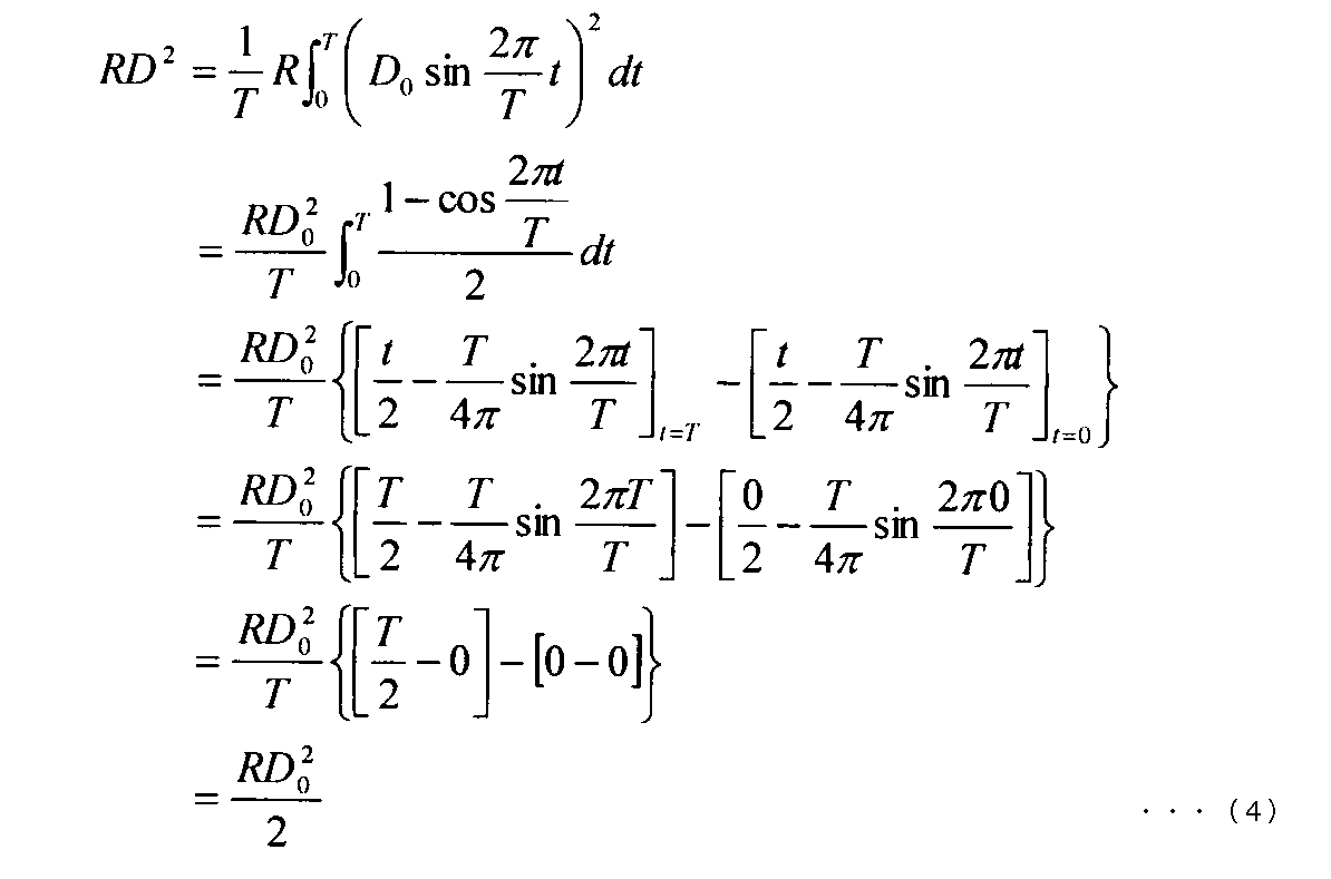
よって、ずり速度の最大値とずり速度の実効値D´の関係は、式(5)となる。
Therefore, the relationship between the maximum value of the shear rate and the effective value D ′ of the shear rate is expressed by Equation (5).

なお、最大ずり速度D0は、式(6)で得られる。
Note that the maximum shear rate D 0 is obtained by Expression (6).

ここで、B:コイルの磁束密度、I0:コイルに流れる最大電流値、L:コイル長、α:振動子のてこ比、η:サンプル液の粘度、A:振動子の接液面積、である。
Here, B: magnetic flux density of the coil, I 0 : maximum current value flowing through the coil, L: coil length, α: leverage ratio of the vibrator, η: viscosity of the sample liquid, A: wetted area of the vibrator is there.
詳細に、電磁駆動部2で発生する力F1は、F1=BIL から求められる。振動子1の接液面中心1oにおける駆動力Fは、電磁駆動部2で発生する力F1を、振動子1の支点となる板バネ4の最薄肉部4aの上下方向中心を基準とし、電磁駆動部2の上下方向中心までの距離d1と振動子の接液部中心1oまでの距離d2の比(てこ比)αで除すことで求められる(図1参照)。この振動子1の接液面中心1oにおける駆動力Fを、振動子1の接液面積A(接液面1aの面積)で割ると、サンプル液9と振動子1間に発生するずり応力Sを求めることができる。よって、式(1)から、サンプル液9の粘度ηが測定できれば、最大ずり速度D0は、コイル22に流れる最大電流値I0をもって、式(6)から得られる。磁束密度B、コイル長L、接液面積Aは、装置構成から既知の値となる。最大電流値I0は、設定する振幅によって測定することで定まる。以上をもって、ずり速度の実効値D´は、演算処理部18にて算出される(ずり速度決定手段)。
Specifically, the force F 1 generated by the electromagnetic drive unit 2 is obtained from F 1 = BIL. Driving force F in the wetted surface center 1o of the vibrator 1, a force F 1 generated by the electromagnetic drive unit 2, with respect to the vertical center of the thinnest portion 4a of the leaf spring 4 as a supporting point of the vibrator 1, It is obtained by dividing by the ratio (leverage ratio) α of the distance d1 to the center in the vertical direction of the electromagnetic drive part 2 and the distance d2 to the liquid contact part center 1o of the vibrator (see FIG. 1). When the driving force F at the liquid contact surface center 1o of the vibrator 1 is divided by the liquid contact area A of the vibrator 1 (area of the liquid contact surface 1a), the shear stress S generated between the sample liquid 9 and the vibrator 1 is obtained. Can be requested. Therefore, if the viscosity η of the sample liquid 9 can be measured from the equation (1), the maximum shear rate D 0 can be obtained from the equation (6) with the maximum current value I 0 flowing through the coil 22. The magnetic flux density B, the coil length L, and the liquid contact area A are known values from the apparatus configuration. The maximum current value I 0 is determined by measuring with the set amplitude. Thus, the effective value D ′ of the shear rate is calculated by the arithmetic processing unit 18 (shear rate determining means).
図4は、本発明に係る音叉振動式粘度計にて、各粘度値におけるずり速度を実効値D´で表示したグラフである。横軸は振動子1の振幅[mm]、縦軸は粘度値[mPa・s]である。測定に使用した音叉振動式粘度計の接液面積Aは0.000304[mm]、てこ比αは3.81、コイル22の磁束密度Bは0.308[Web/m2]、コイル長Lは4[m]であった。また、最大電流値I0は、サンプルによって測定される変数である。
FIG. 4 is a graph showing the shear rate at each viscosity value as an effective value D ′ in the tuning-fork vibration viscometer according to the present invention. The horizontal axis represents the amplitude [mm] of the vibrator 1 and the vertical axis represents the viscosity value [mPa · s]. The liquid contact area A of the tuning fork vibration type viscometer used for the measurement is 0.000304 [mm], the leverage α is 3.81, the magnetic flux density B of the coil 22 is 0.308 [Web / m 2 ], and the coil length L Was 4 [m]. The maximum current value I 0 is a variable measured by the sample.
サンプル液9は、イオン交換水、JIS Z8809に規定の粘度校正用標準液(JS20,JS200,JS2000,JS14000)を各45ml用いた(25℃一定条件下)。測定条件は、各流体、測定時間11分、振幅の下限値0.2mm、上限値1.2mm、振幅の時間割の変化量Δ0.2mm/分、振幅は上昇ののち下降させ、往復させた。また、各流体の粘度(25[℃])は既知(JIS Z8803に準拠)であるため、値を入力して測定を行った。この結果得られたずり速度の実効値D´[1/s]の値を、白枠線内に示した。図4から、同じ振幅を加えても、粘度値によりずり速度(実効値D´)が異なることがわかる。
Sample liquid 9 was 45 ml each of ion-exchanged water and a standard solution for viscosity calibration (JS20, JS200, JS2000, JS14000) defined in JIS Z8809 (under constant conditions at 25 ° C.). The measurement conditions were as follows: each fluid, measurement time 11 minutes, amplitude lower limit value 0.2 mm, upper limit value 1.2 mm, amplitude timetable change Δ0.2 mm / min, amplitude decreased and then reciprocated. Moreover, since the viscosity (25 [° C.]) of each fluid is known (conforms to JIS Z8803), measurement was performed by inputting a value. The value of the effective value D ′ [1 / s] of the shear rate obtained as a result is shown in a white frame. FIG. 4 shows that even if the same amplitude is applied, the shear rate (effective value D ′) varies depending on the viscosity value.
以上により、本発明によれば、音叉振動式粘度計における振動子1が、正弦波的に絶えず往復運動することに着目して、振動子1がその接液面中心1oを中心に接液面1aと平行方向に往復運動するときに流動体(サンプル液9)に作用するずり速度Dを、正弦曲線として表し、実効値 D´=D0/√2 :式(5)として捉えたことで、音叉振動式粘度計においても、ずり速度を決定することができ、ずり速度を定量的に扱うことができる。
As described above, according to the present invention, paying attention to the fact that the vibrator 1 in the tuning fork vibration type viscometer reciprocally moves in a sinusoidal manner, the vibrator 1 is in contact with the liquid contact surface centering on the liquid contact surface center 1o. The shear velocity D acting on the fluid (sample liquid 9) when reciprocating in the direction parallel to 1a is expressed as a sine curve, and effective value D ′ = D 0 / √2: In the tuning fork vibration type viscometer, the shear rate can be determined, and the shear rate can be handled quantitatively.
なお、本発明は、音叉振動式粘度計に限らず、回転振動式粘度計にも適用することができる。
The present invention can be applied not only to a tuning fork vibration type viscometer but also to a rotational vibration type viscometer.
回転振動式(又は捻り振動式)粘度計は、流動体中に浸漬した一の円筒状の振動子を回転方向に共振させ、該振動子が一定の振幅を維持するのに必要となるトルクを測定又は一定のトルクを維持し振幅を測定して、流動体のサンプル液の粘度を測定する装置であるが、この振動式粘度計において、振動子は、回転軸を中心に周期的に回転振動(そのノードを対称に時計回り/反時計回りに周期的に往復振動)する。すなわち、回転振動式粘度計の振動子の回転振動によってサンプル液に加わるずり速度は、音叉振動式粘度計と同様に正弦曲線、式(2)で示せるため、式(3)~式(4)から、回転振動式粘度計においても、式(5)でずり速度を実効値で表すことができる。
A rotational vibration (or torsional vibration) viscometer resonates a cylindrical vibrator immersed in a fluid in the direction of rotation, and generates the torque necessary for the vibrator to maintain a constant amplitude. This is a device that measures the viscosity of a fluid sample liquid by measuring or maintaining a constant torque and measuring the amplitude. In this vibratory viscometer, the vibrator rotates and vibrates periodically around the rotation axis. (The node is reciprocally oscillated periodically in a clockwise / counterclockwise direction). That is, since the shear rate applied to the sample liquid by the rotational vibration of the vibrator of the rotational vibration type viscometer can be expressed by a sinusoidal equation (2) as in the tuning fork vibration type viscometer, the expressions (3) to (4) Therefore, also in the rotational vibration viscometer, the shear rate can be expressed by an effective value by the equation (5).
1 振動子
1a 接液部
1o 接液部中心
2 電磁駆動部
2a ネオジウム磁石
2b 電磁コイル
3 温度センサ
4 板バネ
4a 最薄肉部
5 変位センサ
7 容器
8 中央支持部材(板ばね固定)
9 サンプル液
10 駆動機構部 DESCRIPTION OFSYMBOLS 1 Vibrator 1a Liquid contact part 1o Liquid contact part center 2 Electromagnetic drive part 2a Neodymium magnet 2b Electromagnetic coil 3 Temperature sensor 4 Leaf spring 4a Thinnest part 5 Displacement sensor 7 Container 8 Center support member (plate spring fixation)
9Sample solution 10 Drive mechanism
1a 接液部
1o 接液部中心
2 電磁駆動部
2a ネオジウム磁石
2b 電磁コイル
3 温度センサ
4 板バネ
4a 最薄肉部
5 変位センサ
7 容器
8 中央支持部材(板ばね固定)
9 サンプル液
10 駆動機構部 DESCRIPTION OF
9
Claims (3)
- 流動体中に浸漬した一対の薄振動子を、コイルを備えた電磁駆動部によって振動させ、前記振動子の振幅が設定された振幅値となるように前記コイルに駆動電流を流し、前記駆動電流を測定して流動体の粘度を測定する音叉振動式粘度計における、流動体に発生するずり速度を求める方法であって、
振動子がその接液面中心を中心に接液面と平行方向に振動するときに流動体に作用するずり速度Dを、正弦曲線とし、最大ずり速度D0の1/√2をずり速度の実効値D´として求め、ずり速度の実効値D´を、そのとき流動体に作用しているずり速度として扱うことを特徴とする、流動体に発生するずり速度を求める方法。 A pair of thin vibrators immersed in a fluid is vibrated by an electromagnetic drive unit having a coil, and a drive current is passed through the coils so that the amplitude of the vibrator becomes a set amplitude value. In a tuning fork vibration type viscometer that measures the viscosity of a fluid by measuring a shear rate generated in the fluid,
The shear rate D which acts on the fluid when the vibrator vibrates the wetted surface parallel direction about its wetted surface center, a sine curve, a 1 / √2 of the maximum shear rate D 0 of the shear rate A method for obtaining a shear rate generated in a fluid, characterized in that it is obtained as an effective value D ′, and the effective value D ′ of the shear rate is treated as a shear rate acting on the fluid at that time. - 流動体中に浸漬した一対の薄振動子を、コイルを備えた電磁駆動部によって振動させ、前記振動子の振幅が設定された振幅値となるように前記コイルに駆動電流を流し、前記駆動電流を測定して流動体の粘度を測定する音叉振動式粘度計であって、
振動子がその接液面中心を中心に接液面と平行方向に振動するときに流動体に作用するずり速度Dを、正弦曲線とし、最大ずり速度D0の1/√2をずり速度の実効値D´として求め、ずり速度の実効値D´を、そのとき流動体に作用しているずり速度として扱う、ずり速度決定手段を備えることを特徴とする、音叉振動式粘度計。 A pair of thin vibrators immersed in a fluid is vibrated by an electromagnetic drive unit having a coil, and a drive current is passed through the coils so that the amplitude of the vibrator becomes a set amplitude value. A tuning fork vibratory viscometer that measures the viscosity of a fluid by measuring
The shear rate D which acts on the fluid when the vibrator vibrates the wetted surface parallel direction about its wetted surface center, a sine curve, a 1 / √2 of the maximum shear rate D 0 of the shear rate A tuning fork vibratory viscometer characterized by comprising a shear rate determining means that obtains the effective value D 'as an effective value D' and handles the effective value D 'of the shear rate as a shear rate acting on the fluid at that time. - 流動体中に浸漬した一の振動子を回転方向に共振駆動させ、該振動子が一定の振幅を維持するのに必要となるトルクを測定又は一定のトルクを維持し振幅を測定して、流動体の粘度を測定する回転振動式粘度計における、流動体に発生するずり速度を求める方法であって、
振動子が回転軸を中心に周期的に回転振動するときに流動体に作用するずり速度Dを、正弦曲線とし、最大ずり速度D0の1/√2をずり速度の実効値D´として求め、ずり速度の実効値D´を、そのとき流動体に作用しているずり速度として扱うことを特徴とする、流動体に発生するずり速度を求める方法。 A single vibrator immersed in a fluid is driven to resonate in the rotational direction, and the torque required for the vibrator to maintain a constant amplitude is measured or the amplitude is measured while maintaining a constant torque. In a rotational vibration viscometer for measuring the viscosity of a body, a method for obtaining a shear rate generated in a fluid,
The shear rate D acting on the fluid when the vibrator periodically oscillates around the rotation axis is defined as a sine curve, and 1 / √2 of the maximum shear rate D 0 is obtained as the effective value D ′ of the shear rate. A method for determining a shear rate generated in a fluid, wherein the effective value D ′ of the shear rate is treated as a shear rate acting on the fluid at that time.
Priority Applications (1)
| Application Number | Priority Date | Filing Date | Title |
|---|---|---|---|
| PCT/JP2013/073202 WO2015029196A1 (en) | 2013-08-29 | 2013-08-29 | Method and device for finding shear rate of fluid by vibration-type viscometer |
Applications Claiming Priority (1)
| Application Number | Priority Date | Filing Date | Title |
|---|---|---|---|
| PCT/JP2013/073202 WO2015029196A1 (en) | 2013-08-29 | 2013-08-29 | Method and device for finding shear rate of fluid by vibration-type viscometer |
Publications (1)
| Publication Number | Publication Date |
|---|---|
| WO2015029196A1 true WO2015029196A1 (en) | 2015-03-05 |
Family
ID=52585812
Family Applications (1)
| Application Number | Title | Priority Date | Filing Date |
|---|---|---|---|
| PCT/JP2013/073202 WO2015029196A1 (en) | 2013-08-29 | 2013-08-29 | Method and device for finding shear rate of fluid by vibration-type viscometer |
Country Status (1)
| Country | Link |
|---|---|
| WO (1) | WO2015029196A1 (en) |
Cited By (1)
| Publication number | Priority date | Publication date | Assignee | Title |
|---|---|---|---|---|
| CN108333081A (en) * | 2018-05-16 | 2018-07-27 | 洛阳理工学院 | A kind of paste materials Limiting shear stress test device and test method |
-
2013
- 2013-08-29 WO PCT/JP2013/073202 patent/WO2015029196A1/en active Application Filing
Non-Patent Citations (1)
| Title |
|---|
| NAOTO IZUMO: "Shnin-Hosniki Rheometer ni yori Erareru Kakushu Ekitai no Nensei <Shindo-shiki Rheometer RV-10000>", KEISOKU GIJUTSU, vol. 41, no. 3, 5 February 2013 (2013-02-05), pages 33 - 37 * |
Cited By (2)
| Publication number | Priority date | Publication date | Assignee | Title |
|---|---|---|---|---|
| CN108333081A (en) * | 2018-05-16 | 2018-07-27 | 洛阳理工学院 | A kind of paste materials Limiting shear stress test device and test method |
| CN108333081B (en) * | 2018-05-16 | 2024-02-06 | 洛阳理工学院 | Device and method for testing ultimate shear stress of slurry material |
Similar Documents
| Publication | Publication Date | Title |
|---|---|---|
| CN107278267B (en) | Vibration sensor | |
| JP3135605B2 (en) | Stir bar | |
| WO2014132412A1 (en) | Method for finding shear rate of fluid, and program and device for same | |
| CN104685339A (en) | Method and device for measuring fluid body physical properties | |
| WO2013111608A1 (en) | Viscoelasticity measurement method and viscoelasticity measurement device | |
| RU2727865C2 (en) | Control of oscillations of a vibration sensor based on phase mismatch | |
| CN107110694B (en) | Vibration sensor | |
| WO2015029196A1 (en) | Method and device for finding shear rate of fluid by vibration-type viscometer | |
| JP6169092B2 (en) | Method, program and apparatus for evaluating reach distance of shear rate acting on fluid | |
| JP2015190829A (en) | Method, program, and device for determining yield value of fluid | |
| JPH06241852A (en) | Method and apparatus for measurement of flow rate/ viscosity | |
| Reichel et al. | Droplet mixing and liquid property tracking using an electrodynamic plate resonator | |
| JP7352329B2 (en) | Viscoelasticity measurement method and viscoelasticity measurement device | |
| JP5483113B2 (en) | Viscometer | |
| RU2339007C2 (en) | Coriolis acceleration mass flowmeter and method of measured value representing mass flow | |
| Clara et al. | Theoretical analysis and simulation studies of the orbiting sphere viscometer | |
| JP6651076B1 (en) | Vibration viscometer | |
| RU2503924C1 (en) | Integral micromechanical gyroscope | |
| Reichel et al. | Fluid impedance model for resonator viscosity sensors | |
| Ghosh et al. | Surface modes of a sessile water drop: An optical tweezer based study | |
| Potestio et al. | Discretized knot motion on a tensioned fiber induced by transverse waves | |
| Bansevičius et al. | Analysis of cylindrical piezoelectric actuator used in flow control device | |
| CN104969077B (en) | The resonance needle for measuring and controlling the method and apparatus of a small amount of fluid dosage using needle is resonated and be suitable for this purpose | |
| Rezazadeh et al. | Simultaneous measurement of fluids viscosity and density using a microbeam | |
| Reichel et al. | Microsensors Based on Mechanically Vibrating Structures |
Legal Events
| Date | Code | Title | Description |
|---|---|---|---|
| 121 | Ep: the epo has been informed by wipo that ep was designated in this application |
Ref document number: 13892759 Country of ref document: EP Kind code of ref document: A1 |
|
| NENP | Non-entry into the national phase |
Ref country code: DE |
|
| 122 | Ep: pct application non-entry in european phase |
Ref document number: 13892759 Country of ref document: EP Kind code of ref document: A1 |
|
| NENP | Non-entry into the national phase |
Ref country code: JP |