JP2015174183A - Broach grinding device - Google Patents
Broach grinding device Download PDFInfo
- Publication number
- JP2015174183A JP2015174183A JP2014052274A JP2014052274A JP2015174183A JP 2015174183 A JP2015174183 A JP 2015174183A JP 2014052274 A JP2014052274 A JP 2014052274A JP 2014052274 A JP2014052274 A JP 2014052274A JP 2015174183 A JP2015174183 A JP 2015174183A
- Authority
- JP
- Japan
- Prior art keywords
- broach
- deburring
- deburring brush
- turning
- brush
- Prior art date
- Legal status (The legal status is an assumption and is not a legal conclusion. Google has not performed a legal analysis and makes no representation as to the accuracy of the status listed.)
- Granted
Links
Images


Abstract
Description
本発明は、円盤砥石によってブローチの切刃を研削するブローチカッタ研削盤に関する。 The present invention relates to a broach cutter grinder for grinding a cutting edge of a broach with a disc grindstone.
複数の切刃が軸方向に複数並んで形成されたブローチは、ワークの加工穴等に対して軸方向に1回通すことによって目標とする切削加工を行うことができるものである。そして、ブローチを用いて切削加工を所定の回数行ったときには、切削加工に伴って複数の切刃が摩耗する。そのため、ブローチ研削盤を用いて、摩耗した複数の切刃を研削によって再生している。例えば、特許文献1には、研削砥石によって切刃の研削を行うブローチ研削装置が開示されている。
A broach in which a plurality of cutting blades are formed side by side in the axial direction can perform a target cutting process by passing it once in the axial direction through a machining hole or the like of a workpiece. When the cutting process is performed a predetermined number of times using the broach, the plurality of cutting blades wear with the cutting process. Therefore, a plurality of worn cutting edges are regenerated by grinding using a broach grinder. For example,
また、研削砥石を用いて切刃のすくい面の研削を行った後には、すくい面の周囲には、ブローチの素材の一部が突出したことによるバリが形成される。このバリは、バリ取りブラシを把持する作業者の手作業によって除去されることが多い。また、バリ取りを行う装置としては、例えば、特許文献2に開示されたバリ取り装置がある。このバリ取り装置においては、金属片のバリを回転砥石で研削除去し、残存するバリをさらに回転ワイヤブラシで除去することが開示されている。
In addition, after grinding the rake face of the cutting edge using a grinding wheel, burrs are formed around the rake face due to part of the broach material protruding. This burr is often removed by the manual operation of an operator holding the deburring brush. Moreover, as a deburring apparatus, there exists a deburring apparatus disclosed by
しかしながら、作業者の手作業によってバリ取りを行う場合には、バリの取られ方が、バリ取りブラシの当て方、バリ取りブラシを当てる強さ等によって変化する。そのため、作業者の熟練を必要とするだけでなく、バリの取られ方が作業者によって異なるおそれがある。
また、特許文献2のバリ取り装置は、バリ取りのみを専用に行う装置であり、ブローチ研削盤においてバリ取りを可能にしたものではない。そのため、ブローチの研削及びバリ取りを行うためには、ブローチ研削盤とバリ取り装置とを用いる必要がある。
However, when deburring is performed manually by an operator, the method of deburring varies depending on the method of applying the deburring brush, the strength of applying the deburring brush, and the like. Therefore, not only the skill of the worker is required, but the manner in which the burr is taken may vary depending on the worker.
Further, the deburring device of
本発明は、かかる背景に鑑みてなされたもので、すくい面の研削加工及びバリの除去加工を、小さなスペースで、安定した品質で行うことができるブローチ研削盤を提供しようとして得られたものである。 The present invention has been made in view of such a background, and has been obtained in an attempt to provide a broach grinder capable of performing grinding processing of a rake face and removal processing of burrs in a small space with stable quality. is there.
本発明の一態様は、ブローチの軸方向に複数並ぶ切刃の各すくい面を、円盤砥石によって研削するよう構成されたブローチ研削盤において、
上記ブローチを回転可能に支持するブローチ支持台が設けられた架台と、
該架台において、上記ブローチに対して該ブローチの軸方向に相対移動可能に配設されたコラムと、
該コラムに配設され、上記円盤砥石と、該円盤砥石によって研削をした後の上記すくい面に形成されたバリを除去するためのバリ取りブラシとを支持し、該バリ取りブラシと上記円盤砥石とを別々に回転させる回転ヘッドと、
上記コラムに配設され、上記回転ヘッドを、上記軸方向に直交する水平方向に沿った第1の旋回軸線の回りと、該第1の旋回軸線に直交する第2の旋回軸線の回りとに旋回させる旋回機構と、を備えていることを特徴とするブローチ研削盤にある。
One aspect of the present invention is a broach grinder configured to grind each rake face of a plurality of cutting blades arranged in the axial direction of the broach with a disc grindstone,
A stand provided with a broach support for rotatably supporting the broach;
A column disposed in the frame so as to be relatively movable in the axial direction of the broach with respect to the broach;
The disc grindstone disposed on the column and supporting a deburring brush for removing burrs formed on the rake face after grinding with the disc grindstone, the deburring brush and the disc grindstone Rotating heads that rotate separately, and
The rotary head disposed on the column is arranged around a first turning axis along a horizontal direction perpendicular to the axial direction and around a second turning axis perpendicular to the first turning axis. A broach grinder characterized by comprising a turning mechanism for turning.
上記ブローチ研削盤においては、回転ヘッドが、円盤砥石とバリ取りブラシとを支持して回転するよう構成されている。回転ヘッドは、旋回機構によって旋回可能な状態でコラムに配設されている。
そして、旋回機構によって、回転ヘッドを水平方向の旋回軸線の回りと、上下方向の軸線回りとに旋回させることにより、円盤砥石によってブローチの切刃のすくい面を研削する場合と、バリ取りブラシによってすくい面に形成されたバリを除去する場合とに切り換えることができる。
In the broach grinder, the rotary head is configured to rotate while supporting the disc grindstone and the deburring brush. The rotary head is arranged on the column in a state where it can be turned by a turning mechanism.
Then, by turning the rotary head around the horizontal turning axis and around the vertical axis by the turning mechanism, the rake face of the cutting edge of the broach is ground with a disc grindstone, and the deburring brush is used. It can be switched to the case of removing burrs formed on the rake face.
これにより、1台のブローチ研削盤において、すくい面の研削加工と、すくい面に形成されたバリの除去加工とを行うことができる。そのため、小さなスペースで、すくい面の研削加工及びバリの除去加工を行うことができる。また、作業者の手作業によらず、ブローチ研削盤を用いてバリの除去加工をすることにより、バリ取りの品質を安定させることができる。
それ故、上記ブローチ研削盤によれば、すくい面の研削加工及びバリの除去加工を、小さなスペースで、安定した品質で行うことができる。
Thereby, in one broach grinder, rake surface grinding and burrs formed on the rake surface can be removed. Therefore, it is possible to perform rake surface grinding and burr removal in a small space. Moreover, the quality of deburring can be stabilized by carrying out the deburring process using a broach grinder regardless of the manual work of the operator.
Therefore, according to the broach grinder, rake face grinding and burr removal can be performed in a small space with stable quality.
上述したブローチ研削盤における好ましい実施の形態について説明する。
上記ブローチ研削盤においては、上記複数の切刃は、ワークの加工穴の内周面にスプライン歯を切削するために、軸方向及び周方向に並んで形成されており、上記バリ取りブラシは、径方向外方に放射状に突出する複数のワイヤを有しており、上記バリ取りブラシによって上記バリを除去する際には、上記回転ヘッドによって回転する上記バリ取りブラシが上記ブローチの軸方向に沿って移動して、上記複数のワイヤの先端部が、周方向に並ぶ上記切刃同士の間の溝部に順次配置されるよう構成されていてもよい。
この場合には、バリ取りブラシの複数のワイヤの先端部を、複数の切刃における切刃同士の間の溝部に配置して、バリ取りブラシをブローチの軸方向に繰り返し移動させる。これにより、スプライン歯を形成するブローチについて、バリの除去を迅速かつ安定して行うことができる。
A preferred embodiment of the above broach grinder will be described.
In the broach grinder, the plurality of cutting blades are formed side by side in the axial direction and the circumferential direction in order to cut spline teeth on the inner peripheral surface of the work hole of the workpiece. A plurality of wires projecting radially outwards are provided, and when the deburring brush is removed by the deburring brush, the deburring brush rotated by the rotating head extends along the axial direction of the broach. The tip portions of the plurality of wires may be sequentially arranged in the groove portions between the cutting blades arranged in the circumferential direction.
In this case, the tips of the plurality of wires of the deburring brush are arranged in the grooves between the cutting edges of the plurality of cutting edges, and the deburring brush is repeatedly moved in the axial direction of the broach. Thereby, about the broach which forms a spline tooth, the removal of a burr | flash can be performed rapidly and stably.
また、上記複数の切刃は、ワークの加工穴の内周面にヘリカル歯を切削するために、上記ブローチの中心軸線の回りに捩じられながら軸方向及び周方向に並んでおり、上記バリ取りブラシは、径方向外方に放射状に突出する複数のワイヤを有しており、上記バリ取りブラシによって上記バリを除去する際には、上記回転ヘッドによって回転する上記バリ取りブラシが、上記ブローチ支持台によって回転する上記ブローチの軸方向に沿って該ブローチに対して相対移動して、上記複数のワイヤの先端部が、周方向に並ぶ上記切刃同士の間の溝部に順次配置されるよう構成されていてもよい。
この場合には、バリ取りブラシの複数のワイヤの先端部を、複数の切刃における切刃同士の間の溝部に配置して、バリ取りブラシをブローチの軸方向に繰り返し移動させる。これにより、ヘリカル歯を形成するブローチについて、バリの除去を迅速かつ安定して行うことができる。
The plurality of cutting blades are arranged in the axial direction and the circumferential direction while being twisted around the central axis of the broach in order to cut helical teeth on the inner peripheral surface of the work hole of the workpiece. The deburring brush has a plurality of wires radially projecting radially outward. When the deburring brush is removed by the deburring brush, the deburring brush rotated by the rotating head is It moves relative to the broach along the axial direction of the broach rotated by the support base, and the tip portions of the plurality of wires are sequentially arranged in the grooves between the cutting blades arranged in the circumferential direction. It may be configured.
In this case, the tips of the plurality of wires of the deburring brush are arranged in the grooves between the cutting edges of the plurality of cutting edges, and the deburring brush is repeatedly moved in the axial direction of the broach. Thereby, about the broach which forms a helical tooth, a burr | flash removal can be performed rapidly and stably.
また、上記コラムは、ワークを切削する時の上記ブローチの切削方向であって、上記複数の切刃における上記すくい面の形成側とは反対側から上記形成側へ向けて、上記回転ヘッドに支持された上記バリ取りブラシを移動させるよう構成されており、上記回転ヘッドによって回転する上記バリ取りブラシの、上記バリを除去する位置における周速方向は、上記バリ取りブラシの移動方向と同じであってもよい。
この場合には、バリ取りブラシの移動方向及び回転方向が適切であり、複数の切刃のすくい面に形成されたバリの除去を効果的に行うことができる。
The column is supported by the rotary head in the cutting direction of the broach when cutting a workpiece, from the side opposite to the rake face formation side of the plurality of cutting blades toward the formation side. The deburring brush is moved, and the circumferential speed direction of the deburring brush rotated by the rotary head at the position where the deburring is removed is the same as the movement direction of the deburring brush. May be.
In this case, the moving direction and the rotating direction of the deburring brush are appropriate, and it is possible to effectively remove the burrs formed on the rake surfaces of the plurality of cutting blades.
また、上記回転ヘッドは、上記円盤砥石の中心軸線と上記バリ取りブラシの中心軸線とが平行な状態で、該円盤砥石と該バリ取りブラシとを支持しており、上記旋回機構は、上記水平方向に沿った旋回軸線の回りに上記円盤砥石及び上記バリ取りブラシを旋回させる水平旋回軸と、上記上下方向に沿った旋回軸線の回りに上記円盤砥石及び上記バリ取りブラシを旋回させる上下旋回軸とを有しており、かつ、上記水平旋回軸を回転させて、上記ブローチに対向させる、上記円盤砥石と上記バリ取りブラシとを切換可能であり、上記上下旋回軸を回転させて、上記ブローチの中心軸線に対する、上記円盤砥石と上記バリ取りブラシとの傾斜角度を切換可能であってもよい。
この場合には、円盤砥石によってブローチの切刃のすくい面を研削する場合と、バリ取りブラシによってすくい面に形成されたバリを除去する場合との切換えを容易にすることができる。
The rotary head supports the disc grindstone and the deburring brush in a state where the center axis of the disc grindstone and the center axis of the deburring brush are parallel to each other. A horizontal turning shaft for turning the disc grindstone and the deburring brush around a turning axis along the direction, and a vertical turning shaft for turning the disc grindstone and the deburring brush around the turning axis along the up-down direction. The disc grindstone and the deburring brush can be switched to rotate the horizontal swivel shaft to face the broach, and rotate the vertical swivel shaft to rotate the broach. The angle of inclination of the disc grindstone and the deburring brush with respect to the central axis of each other may be switchable.
In this case, it is possible to easily switch between grinding the rake face of the cutting edge of the broach with a disc grindstone and removing burrs formed on the rake face with a deburring brush.
以下に、ブローチ研削盤にかかる実施例について、図面を参照して説明する。
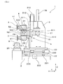
本例のブローチ研削盤1は、図7に示すように、ブローチ8の軸方向Lに複数並ぶ切刃81の各すくい面811を、円盤砥石6によって研削するよう構成されている。
ブローチ研削盤1は、図1、図2に示すように、架台2、コラム3、回転ヘッド4及び旋回機構5を備えている。架台2には、ブローチ8を回転可能に支持するブローチ支持台21が一対に設けられている。コラム3は、架台2において、ブローチ8に対してブローチ8の軸方向Lに相対移動可能に配設されている。回転ヘッド4は、コラム3に配設されており、円盤砥石6と、バリ取りブラシ7とを支持するよう構成されている。
Below, the example concerning a broach grinder is described with reference to drawings.
As shown in FIG. 7, the
As shown in FIGS. 1 and 2, the
バリ取りブラシ7は、図8に示すように、円盤砥石6によって研削をした後のすくい面811に形成されたバリ85を除去するために用いられる。また、図2に示すように、回転ヘッド4は、バリ取りブラシ7と円盤砥石6とを別々に回転させるよう構成されている。旋回機構5は、コラム3に配設されており、回転ヘッド4を、軸方向Lに直交する水平方向Yに沿った第1の旋回軸線C1の回りと、第1の旋回軸線C1に直交する第2の旋回軸線C2の回りとに旋回させるよう構成されている。
As shown in FIG. 8, the
以下に、本例のブローチ研削盤1について、図1〜図10を参照して詳説する。
図1に示すように、本例のブローチ研削盤1は、ブローチ8の複数の切刃81が摩耗した際に、この複数の切刃81を研削して再生するものである。ブローチ8における複数の切刃81は、ワークの加工穴の一方向に通過させて、ワークに対する切削深さを順次深くするために、軸方向Lの一方から他方に向けて、ブローチ8の中心軸線Oからの半径距離が順次大きくなっている。また、複数の切刃81には、荒削りを行う複数の切刃81Aと、仕上げ削りを行う複数の切刃81Bとがある。
Hereinafter, the
As shown in FIG. 1, the
図9に示すように、本例のブローチ8は、ワークの加工穴の内周面に対してヘリカルギヤを形成するものである。ブローチ8の複数の切刃81は、ワークの加工穴の内周面にヘリカル歯を切削するために、軸方向Lに並ぶとともに周方向Eに並んでいる。複数の切刃81は、ブローチ8の中心軸線Oの回りに捩じられながら並んでいる。周方向Eに並ぶ切刃81同士の間に形成された溝部83は、ブローチ8の中心軸線Oに対して所定のねじれ傾斜角αを有して軸方向Lに並んでいる。また、複数の切刃81は、周方向Eに対しても所定のねじれ角度βで捩じれて配置されている。複数の切刃81は、ブローチ8の中心軸線Oの回りに螺旋状に連続して形成されている。
As shown in FIG. 9, the
図1、図3に示すように、一対のブローチ支持台21は、ブローチ8の両端部を支持する。一対のブローチ支持台21は、架台2に設けられたテーブル20の上に配置されている。架台2及びテーブル20は、ブローチ8の軸方向Lに長い形状に形成されている。一対のブローチ支持台21のうちのいずれか一方は、モータ211によってブローチ8を回転させるよう構成されており、他方は、ブローチ8の回転に従って回転するよう構成されている。
回転ヘッド4が設けられたコラム3は、架台2の長手方向X(X方向)、軸方向Lに直交する水平方向Y(Y方向)、及び長手方向X及び水平方向Yに直交する上下方向Z(Z方向)にそれぞれ移動可能に構成されている。
As shown in FIGS. 1 and 3, the pair of
The
図1〜図3に示すように、架台2には、コラム3をX方向に案内するためのリニヤガイド221と、コラム3をX方向に駆動するためのモータ222と、モータ222による回転力を直線駆動力に変換するためのネジ機構223と、ネジ機構223によってX方向にスライドするX方向スライダー22とが設けられている。
X方向スライダー22には、コラム3をY方向に案内するためのリニヤガイド231と、コラム3をY方向に駆動するためのモータ232と、モータ232による回転力を直線駆動力に変換するためのネジ機構233と、ネジ機構233によってY方向にスライドするY方向スライダー23とが設けられている。
As shown in FIGS. 1 to 3, the
The
図1、図2に示すように、回転ヘッド4を支持するコラム3は、Y方向スライダー23に設けられている。コラム3は、回転ヘッド4を取り付けるためのブラケットによって構成されている。コラム3は、回転ヘッド4に支持する円盤砥石6及びバリ取りブラシ7が上下方向Zに並んで配置される高さに形成されている。
コラム3には、回転ヘッド4をZ方向に案内するためのリニヤガイド311と、回転ヘッド4をZ方向に駆動するためのモータ312と、モータ312による回転力を直線駆動力に変換するためのネジ機構313と、ネジ機構313によってZ方向にスライドするZ方向スライダー31とが設けられている。また、コラム3には、回転ヘッド4に加わる重力が、回転ヘッド4をZ方向に駆動するためのモータ312に作用することを緩和するための重力バランサ32が設けられている。重力バランサ32は、エアシリンダによって構成されており、エアシリンダによる推力を、重力が作用する鉛直方向とは反対方向に作用させるよう構成されている。
As shown in FIGS. 1 and 2, the
The
図2に示すように、回転ヘッド4は、円盤砥石6の回転中心軸である中心軸線D1とバリ取りブラシ7の回転中心軸である中心軸線D2とが平行な状態で、円盤砥石6とバリ取りブラシ7とを支持している。旋回機構5は、水平方向Yに沿った第1の旋回軸線C1の回りに円盤砥石6及びバリ取りブラシ7を旋回させる水平旋回軸511と、第1の旋回軸線C1に対して直交する第2の旋回軸線C2の回りに円盤砥石6及びバリ取りブラシ7を旋回させる上下旋回軸521とを有している。
As shown in FIG. 2, the
回転ヘッド4は、水平旋回軸511を挟む両側であって、水平旋回軸511の回りの位相が180°異なる位置に、円盤砥石6を支持する支持部41と、バリ取りブラシ7を支持する支持部41とを配置して構成されている。各支持部41には、円盤砥石6とバリ取りブラシ7とをそれぞれ回転させるためのモータ411が配置されている。円盤砥石6の回転中心軸である中心軸線D1とバリ取りブラシ7の回転中心軸である中心軸線D2とは、旋回軸線C2に対して直交する方向に配置されている。また、各支持部41は、円盤砥石6とバリ取りブラシ7とをそれぞれ着脱可能に構成されている。円盤砥石6とバリ取りブラシ7とは、いずれの支持部41に取り付けることもできる。
The
図1、図2に示すように、旋回機構5は、水平旋回軸511を回転させるための水平機構部51と、上下旋回軸521を回転させるための上下機構部52とを有している。水平機構部51は、Z方向スライダー31に設けられており、水平旋回軸511の他に、水平旋回軸511を回転可能に支持する回転支持部512と、水平旋回軸511を駆動するモータ513と、水平旋回軸511に取り付けられた旋回ブラケット514とを有している。上下機構部52は、旋回ブラケット514に設けられており、上下旋回軸521の他に、上下旋回軸521を回転可能に支持する回転支持部522と、上下旋回軸521を駆動するモータ523と、上下旋回軸521に取り付けられた旋回部524とを有している。各モータ411によって各支持部41を別々に駆動する回転ヘッド4は、旋回部524に設けられている。
As shown in FIGS. 1 and 2, the
水平機構部51は、水平旋回軸511を回転させて、円盤砥石6とバリ取りブラシ7とのいずれをブローチ8に対向させるかを切換可能である。回転ヘッド4に支持された円盤砥石6及びバリ取りブラシ7は、一対のブローチ支持台21に支持されたブローチ8よりも上方に配置されている。そして、水平機構部51の動作によって、円盤砥石6とバリ取りブラシ7とのうち下側に配置された方が、ブローチ8に対向する。また、図3、図4に示すように、水平機構部51は、水平旋回軸511を所定角度回転させることにより、円盤砥石6を、ブローチ8の各切刃81のすくい面811を研削する角度に設定する。そして、円盤砥石6の外周先端部61は、軸方向Lに並ぶ切刃81同士の間のポケット82に配置される。
The
図3、図4においては、円盤砥石6の中心軸線D1が、ブローチ8の中心軸線Oに平行な状態を示す。周方向E(図9参照)に対する、複数の切刃81のねじれ角度βが0(ゼロ)である場合には、切刃81のすくい面81に研削加工を行う際の円盤砥石6の中心軸線D1を、ブローチ8の中心軸線Oに上下方向Zから見て平行になるようにする。この場合には、円盤砥石6は、周方向Eに並ぶ複数の切刃81の研削を、軸方向Lに並ぶ複数の切刃81に対して逐次繰り返す。
一方、周方向Eに対する、複数の切刃81のねじれ角度βが設定されている場合(図9参照)には、研削加工を行う際の円盤砥石6の中心軸線D1を、ねじれ角度βを有するポケット82に直交させる。この場合には、軸方向L及び周方向Eに並ぶ複数の切刃81の研削は、円盤砥石6がブローチ8の中心軸線Oに平行に移動し、ブローチ8の外周を螺旋状に相対移動して行われる。
3 and 4, the center axis D <b> 1 of the
On the other hand, when the twist angle β of the plurality of cutting
上下機構部52は、上下旋回軸521を回転させて、ブローチ8の中心軸線Oに対する、円盤砥石6の中心軸線D1とバリ取りブラシ7の中心軸線D2との傾斜角度を切換可能である。図5、図6に示すように、バリ取りブラシ7によって各切刃81の研削後に生じたバリ85を除去するときには、上下機構部52の上下旋回軸521を回転させて、バリ取りブラシ7の中心軸線D2が、ブローチ8の各切刃81のねじれ傾斜角αに直交する状態に設定される。
The
図5、図6においては、バリ取りブラシ7の中心軸線D2が、ブローチ8の中心軸線Oに直交する状態を示す。軸方向Lに対する複数の切刃81のねじれ傾斜角αが0(ゼロ)である場合には、バリ取りを行う際のバリ取りブラシ7の中心軸線D2を、ブローチ8の中心軸線Oに直交する状態にする。ワークの加工穴の内周面にスプライン歯を形成するブローチ8の研削及びバリ取りを行う場合には、バリ取りブラシ7の中心軸線D2に直交するバリ取り方向は、ブローチ8の中心軸線Oに合わせて決定される。
5 and 6 show a state in which the central axis D2 of the
一方、軸方向Lに対する複数の切刃81のねじれ傾斜角αが設定されている場合(図9参照)には、バリ取りを行う際のバリ取りブラシ7の中心軸線D2を、ねじれ傾斜角αを有する溝部83に直交させる。本例においては、ワークの加工穴の内周面にヘリカル歯を形成するブローチ8の研削及びバリ取りを行うため、バリ取りブラシ7の中心軸線D2に直交するバリ取り方向は、ブローチ8のねじれ傾斜角αに合わせて設定される。
こうして、上下機構部52による上下旋回軸521の角度調整により、バリ取りブラシ7が、各切刃81のすくい面811に形成されたバリ85を除去する角度に設定される。
On the other hand, when the twist inclination angle α of the plurality of cutting
Thus, by adjusting the angle of the
バリ取りブラシ7は、図10(a)に示すように、回転ヘッド4の支持部41に取り付けられる中心部711と、中心部711の径方向外方に放射状に突出する複数のワイヤからなるワイヤ部712とを有している。中心部711は、支持部41におけるモータ411の出力軸が挿入される中心穴710を有する円環形状に形成されている。バリ取りブラシ7は、図10(b)に示すように、中心部711及びワイヤ部712を有するブラシプレート71を周方向に複数並べて形成されている。
As shown in FIG. 10A, the
次に、ブローチ研削盤1によって研削及びバリ取りを行う方法、及び作用効果について説明する。
ブローチ研削盤1において、各切刃81のすくい面811を研削する際には、図3、図4、図7に示すように、水平機構部51及び上下機構部52によって、回転ヘッド4における円盤砥石6の外周先端部61を、軸方向Lに並ぶ切刃81同士の間のポケット82に配置する。そして、回転ヘッド4によって円盤砥石6を回転させるとともに、一対のブローチ支持台21によってブローチ8を回転させる。
Next, a method of performing grinding and deburring by the
When grinding the
このとき、円盤砥石6の外周先端部61が回転しながら切刃81の周方向Eに並ぶ切刃81の全体に順次接触し、複数の切刃81のすくい面811の全体が研削される。そして、複数の切刃81の全体が再生され、各切刃81のすくい面811の縁部には、円盤砥石6がすくい面811を研削した際に突出するバリ85が形成される。
また、コラム3の移動によって、回転ヘッド4及び円盤砥石6を、ブローチ8の各切刃81の軸方向Lへの形成ピッチに応じてブローチ8の軸方向Lへ順次送る。
At this time, the outer
Further, by the movement of the
次いで、ブローチ研削盤1において、各切刃81のすくい面811に形成されたバリ85を除去する際には、図5、図6、図8に示すように、水平機構部51及び上下機構部52によって、回転ヘッド4におけるバリ取りブラシ7のワイヤ部712の先端部を、周方向Eに並ぶ切刃81同士の間の溝部83に配置する。そして、回転ヘッド4によってバリ取りブラシ7を回転させるとともに、一対のブローチ支持台21によってブローチ8を回転させる。このとき、ブローチ8を回転させる速度は、バリ取りブラシ7のワイヤ部712の先端部が、複数の切刃81によるねじれ傾斜角αに沿って溝部83に配置される速度とする。
Next, when removing the
また、このとき、図8、図9に示すように、ブラシ部712の先端部は、切刃81の先端(すくい面811と逃げ面812が交差する位置)に接触する。そして、切刃81のすくい面811の全体に形成されたバリ85が除去される。
また、バリ取りブラシ7によってバリ85を除去する際には、コラム3の移動によって、回転ヘッド4によって回転するバリ取りブラシ7が、一対のブローチ支持台21によって回転するブローチ8の軸方向Lに沿ってブローチ8に対して相対移動する。そして、バリ取りブラシ7のワイヤ部712の先端部が、複数の切刃81同士の間の溝部83に沿って順次配置される。また、バリ取りブラシ7は、ブローチ8の軸方向Lに繰り返し移動して、複数の溝部83の全体に対してバリ85の除去を行う。
At this time, as shown in FIGS. 8 and 9, the tip of the
Further, when the
また、図8に示すように、回転ヘッド4に支持されたバリ取りブラシ7は、ワークを切削する時のブローチ8の切削方向Mであって、複数の切刃81におけるすくい面811の形成側とは反対側から形成側へ向けて移動して、バリ85の除去を行う。また、バリ取りブラシ7の、バリ85を除去する位置における周速方向Vは、バリ取りブラシ7の移動方向Mと同じとする。そして、バリ取りブラシ7のワイヤ部712の先端部が、バリ85の裏面側852(円盤砥石6と接触しない側)に接触する。また、バリ取りブラシ7の移動による力と、バリ取りブラシ7の回転力とが、バリ85の裏面側852から表面側851に向けて作用する。
Further, as shown in FIG. 8, the
ここで、バリ85は、すくい面811の側である表面側851から裏面側852へ折り曲げる場合に比べて、裏面側852から表面側851へ折り曲げる場合の方が、折れやすい。そのため、バリ取りブラシ7の移動方向M及び回転による周速方向Vを、上記のようにバリ85の裏面側852から表面側851へ向けることにより、バリ85の除去を迅速かつ安定して行うことができる。
Here, the
本例のブローチ研削盤1においては、旋回機構5の水平機構部51及び上下機構部52によって、回転ヘッド4を第1の旋回軸線C1の回りと、第2の旋回軸線C2の回りとに旋回させる。これにより、円盤砥石6によってブローチ8の切刃81のすくい面811を研削する場合と、バリ取りブラシ7によってすくい面811に形成されたバリ85を除去する場合とに切り換えることができる。
In the
そして、1台のブローチ研削盤1において、すくい面811の研削加工と、すくい面811に形成されたバリ85の除去加工とを行うことができる。そのため、小さなスペースで、すくい面811の研削加工及びバリ85の除去加工を行うことができる。また、作業者の手作業によらず、ブローチ研削盤1を用いてバリ85の除去加工をすることにより、バリ取りの品質を安定させることができる。
それ故、本例のブローチ研削盤1によれば、すくい面811の研削加工及びバリ85の除去加工を、小さなスペースで、安定した品質で行うことができる。
Then, in one
Therefore, according to the
なお、ワークの加工穴の内周面にスプライン歯を形成するブローチ8のバリ取りを行う場合には、ブローチ研削盤1においては、回転を停止させたブローチ8の軸方向Lに向けて、回転ヘッド4によって回転するバリ取りブラシ7が移動する。そして、バリ取りブラシ7のワイヤ部712の先端部が、周方向Eに並ぶ切刃81同士の間の溝部83に配置されて、バリ取りが行われる。
When deburring the
また、切刃81が周方向Eに環状に形成されたブローチ8のバリ取りを行う際には、バリ取りブラシ7の中心軸線D2をブローチ8の中心軸線Oと平行に配置する。この場合には、バリ取りブラシ7によって、軸方向Lに並ぶ切刃81同士の間の環状のポケット82に沿って、切刃81のすくい面811に形成されたバリ取りを行うことができる。
Further, when deburring the
1 ブローチ研削盤
2 架台
21 ブローチ支持台
3 コラム
4 回転ヘッド
5 旋回機構
6 円盤砥石
7 バリ取りブラシ
8 ブローチ
81 切刃
811 すくい面
85 バリ
DESCRIPTION OF
Claims (5)
上記ブローチを回転可能に支持するブローチ支持台が設けられた架台と、
該架台において、上記ブローチに対して該ブローチの軸方向に相対移動可能に配設されたコラムと、
該コラムに配設され、上記円盤砥石と、該円盤砥石によって研削をした後の上記すくい面に形成されたバリを除去するためのバリ取りブラシとを支持し、該バリ取りブラシと上記円盤砥石とを別々に回転させる回転ヘッドと、
上記コラムに配設され、上記回転ヘッドを、上記軸方向に直交する水平方向に沿った第1の旋回軸線の回りと、該第1の旋回軸線に直交する第2の旋回軸線の回りとに旋回させる旋回機構と、を備えていることを特徴とするブローチ研削盤。 In a broach grinder configured to grind each rake face of a plurality of cutting blades arranged in the axial direction of the broach with a disc grindstone,
A stand provided with a broach support for rotatably supporting the broach;
A column disposed in the frame so as to be relatively movable in the axial direction of the broach with respect to the broach;
The disc grindstone disposed on the column and supporting a deburring brush for removing burrs formed on the rake face after grinding with the disc grindstone, the deburring brush and the disc grindstone Rotating heads that rotate separately, and
The rotary head disposed on the column is arranged around a first turning axis along a horizontal direction perpendicular to the axial direction and around a second turning axis perpendicular to the first turning axis. A broach grinder characterized by comprising a turning mechanism for turning.
上記バリ取りブラシは、径方向外方に放射状に突出する複数のワイヤを有しており、
上記バリ取りブラシによって上記バリを除去する際には、上記回転ヘッドによって回転する上記バリ取りブラシが上記ブローチの軸方向に沿って移動して、上記複数のワイヤの先端部が、周方向に並ぶ上記切刃同士の間の溝部に順次配置されるよう構成されていることを特徴とする請求項1に記載のブローチ研削盤。 The plurality of cutting blades are formed side by side in the axial direction and the circumferential direction in order to cut spline teeth on the inner peripheral surface of the machining hole of the workpiece,
The deburring brush has a plurality of wires projecting radially outward in the radial direction,
When removing the deburring with the deburring brush, the deburring brush rotated by the rotary head moves along the axial direction of the broach, and the tips of the plurality of wires are arranged in the circumferential direction. The broach grinder according to claim 1, wherein the broach grinder is configured to be sequentially disposed in a groove portion between the cutting blades.
上記バリ取りブラシは、径方向外方に放射状に突出する複数のワイヤを有しており、
上記バリ取りブラシによって上記バリを除去する際には、上記回転ヘッドによって回転する上記バリ取りブラシが、上記ブローチ支持台によって回転する上記ブローチの軸方向に沿って該ブローチに対して相対移動して、上記複数のワイヤの先端部が、周方向に並ぶ上記切刃同士の間の溝部に順次配置されるよう構成されていることを特徴とする請求項1に記載のブローチ研削盤。 The plurality of cutting blades are arranged in the axial direction and the circumferential direction while being twisted around the central axis of the broach in order to cut helical teeth on the inner peripheral surface of the work hole of the workpiece,
The deburring brush has a plurality of wires projecting radially outward in the radial direction,
When the burrs are removed by the deburring brush, the deburring brush rotated by the rotary head moves relative to the broach along the axial direction of the broach rotated by the broach support. 2. The broach grinder according to claim 1, wherein tip ends of the plurality of wires are sequentially arranged in a groove portion between the cutting blades arranged in the circumferential direction.
上記回転ヘッドによって回転する上記バリ取りブラシの、上記バリを除去する位置における周速方向は、上記バリ取りブラシの移動方向と同じであることを特徴とする請求項1〜3のいずれか一項に記載のブローチ研削盤。 The column is supported by the rotating head in the cutting direction of the broach when cutting a workpiece and from the side opposite to the rake face forming side of the plurality of cutting blades toward the forming side. It is configured to move the deburring brush,
The peripheral speed direction of the deburring brush rotated by the rotating head at a position where the deburring is removed is the same as the moving direction of the deburring brush. Broach grinder described in 1.
上記旋回機構は、上記水平方向に沿った旋回軸線の回りに上記円盤砥石及び上記バリ取りブラシを旋回させる水平旋回軸と、上記上下方向に沿った旋回軸線の回りに上記円盤砥石及び上記バリ取りブラシを旋回させる上下旋回軸とを有しており、かつ、上記水平旋回軸を回転させて、上記ブローチに対向させる、上記円盤砥石と上記バリ取りブラシとを切換可能であり、上記上下旋回軸を回転させて、上記ブローチの中心軸線に対する、上記円盤砥石と上記バリ取りブラシとの傾斜角度を切換可能であることを特徴とする請求項1〜4のいずれか一項に記載のブローチ研削盤。 The rotary head supports the disc grindstone and the deburring brush in a state where the center axis of the disc grindstone and the center axis of the deburring brush are parallel to each other.
The turning mechanism includes a horizontal turning shaft for turning the disc grindstone and the deburring brush around the turning axis along the horizontal direction, and the disc grindstone and the deburring around the turning axis along the vertical direction. A vertical turning shaft for turning the brush, and the horizontal turning shaft is rotated to be opposed to the broach so that the disc grinding wheel and the deburring brush can be switched, and the up and down turning shaft The broach grinder according to any one of claims 1 to 4, wherein the inclination angle of the disc grindstone and the deburring brush with respect to the central axis of the broach can be switched by rotating .
Priority Applications (1)
| Application Number | Priority Date | Filing Date | Title |
|---|---|---|---|
| JP2014052274A JP6212418B2 (en) | 2014-03-14 | 2014-03-14 | Broach grinder |
Applications Claiming Priority (1)
| Application Number | Priority Date | Filing Date | Title |
|---|---|---|---|
| JP2014052274A JP6212418B2 (en) | 2014-03-14 | 2014-03-14 | Broach grinder |
Publications (2)
| Publication Number | Publication Date |
|---|---|
| JP2015174183A true JP2015174183A (en) | 2015-10-05 |
| JP6212418B2 JP6212418B2 (en) | 2017-10-11 |
Family
ID=54253853
Family Applications (1)
| Application Number | Title | Priority Date | Filing Date |
|---|---|---|---|
| JP2014052274A Active JP6212418B2 (en) | 2014-03-14 | 2014-03-14 | Broach grinder |
Country Status (1)
| Country | Link |
|---|---|
| JP (1) | JP6212418B2 (en) |
Cited By (4)
| Publication number | Priority date | Publication date | Assignee | Title |
|---|---|---|---|---|
| WO2018030675A1 (en) * | 2016-08-08 | 2018-02-15 | 김인수 | Machine for polishing carbon jig/carbon mold for producing portable device glass |
| TWI627024B (en) * | 2017-05-25 | 2018-06-21 | Numerical control machine for deburring | |
| CN112571238A (en) * | 2020-12-03 | 2021-03-30 | 北京理工大学 | Special grinding and polishing composite grinding tool fast switching device for robot |
| KR102579374B1 (en) * | 2022-12-16 | 2023-09-18 | 주식회사 씨앤엘 | Deburring Manchine |
Citations (7)
| Publication number | Priority date | Publication date | Assignee | Title |
|---|---|---|---|---|
| US3762106A (en) * | 1971-08-11 | 1973-10-02 | Lapointe Machine Tool Co | Attachment for broach sharpening machine |
| JPS4943351Y1 (en) * | 1968-04-12 | 1974-11-27 | ||
| JPS5473587U (en) * | 1977-11-04 | 1979-05-25 | ||
| JPH0890398A (en) * | 1994-09-22 | 1996-04-09 | Nisshin Steel Co Ltd | Method and device for deburring metal piece |
| JPH1148112A (en) * | 1997-07-31 | 1999-02-23 | Mazda Motor Corp | Deburring method, and device therefor |
| JP2005186256A (en) * | 2003-12-26 | 2005-07-14 | Nachi Fujikoshi Corp | Grinder and machining method for grinding tooth flank of tool |
| JP2008213050A (en) * | 2007-02-28 | 2008-09-18 | Toyota Motor Corp | Broach grinding device and method |
-
2014
- 2014-03-14 JP JP2014052274A patent/JP6212418B2/en active Active
Patent Citations (7)
| Publication number | Priority date | Publication date | Assignee | Title |
|---|---|---|---|---|
| JPS4943351Y1 (en) * | 1968-04-12 | 1974-11-27 | ||
| US3762106A (en) * | 1971-08-11 | 1973-10-02 | Lapointe Machine Tool Co | Attachment for broach sharpening machine |
| JPS5473587U (en) * | 1977-11-04 | 1979-05-25 | ||
| JPH0890398A (en) * | 1994-09-22 | 1996-04-09 | Nisshin Steel Co Ltd | Method and device for deburring metal piece |
| JPH1148112A (en) * | 1997-07-31 | 1999-02-23 | Mazda Motor Corp | Deburring method, and device therefor |
| JP2005186256A (en) * | 2003-12-26 | 2005-07-14 | Nachi Fujikoshi Corp | Grinder and machining method for grinding tooth flank of tool |
| JP2008213050A (en) * | 2007-02-28 | 2008-09-18 | Toyota Motor Corp | Broach grinding device and method |
Cited By (4)
| Publication number | Priority date | Publication date | Assignee | Title |
|---|---|---|---|---|
| WO2018030675A1 (en) * | 2016-08-08 | 2018-02-15 | 김인수 | Machine for polishing carbon jig/carbon mold for producing portable device glass |
| TWI627024B (en) * | 2017-05-25 | 2018-06-21 | Numerical control machine for deburring | |
| CN112571238A (en) * | 2020-12-03 | 2021-03-30 | 北京理工大学 | Special grinding and polishing composite grinding tool fast switching device for robot |
| KR102579374B1 (en) * | 2022-12-16 | 2023-09-18 | 주식회사 씨앤엘 | Deburring Manchine |
Also Published As
| Publication number | Publication date |
|---|---|
| JP6212418B2 (en) | 2017-10-11 |
Similar Documents
| Publication | Publication Date | Title |
|---|---|---|
| JP4648219B2 (en) | Gear grinding machine | |
| JP5285416B2 (en) | Internal gear grinding machine and barrel threading tool dressing method | |
| JP5210033B2 (en) | Method and grinding machine for shaping a grinding tool | |
| KR101913918B1 (en) | Cutter for skiving | |
| JP6212418B2 (en) | Broach grinder | |
| JP5244577B2 (en) | Internal gear grinding machine | |
| JP5351700B2 (en) | Manufacturing method for barrel-shaped screw-like tools | |
| JP5360623B2 (en) | Grinding machine for double-sided flat workpiece | |
| KR20120030566A (en) | Method for machining internally toothed gear and method for dressing tool used for same | |
| JP2010253674A (en) | Method and apparatus for removing secondary burr on end-cut workpiece wheel | |
| JP2017530016A (en) | Method of machining teeth, machining tool, and machine tool | |
| JP2014500153A (en) | Method for machining the casing of an aircraft turboshaft engine and scraper tool for carrying out said method | |
| US3722144A (en) | Method and machine to de-bur commutator bars | |
| KR101410564B1 (en) | A Complex Grinding Machine | |
| CN207668610U (en) | A kind of pipe cutting equipment | |
| JP5854792B2 (en) | Dressing method for hourglass gear wheel and disk-shaped dresser | |
| JP5383556B2 (en) | Truing method for grinding wheel for gear grinding and gear grinding machine | |
| US2367850A (en) | Method of machining curved serrations in flat surfaces | |
| JP6819099B2 (en) | Gear processing method | |
| CN109623601A (en) | It is a kind of to be driven the double dynamical high-precision abrasive machine of grinding workpieces intelligently switched | |
| JP5290084B2 (en) | Grinding equipment | |
| JP3135410U (en) | Deburring device for large gears | |
| JP6815913B2 (en) | Worm processing equipment, worm processing method and worm | |
| JP6563241B2 (en) | Grinding wheel forming method of grinding wheel | |
| JP5524397B2 (en) | Manufacturing method for barrel-shaped screw-like tools |
Legal Events
| Date | Code | Title | Description |
|---|---|---|---|
| A621 | Written request for application examination |
Free format text: JAPANESE INTERMEDIATE CODE: A621 Effective date: 20160803 |
|
| A977 | Report on retrieval |
Free format text: JAPANESE INTERMEDIATE CODE: A971007 Effective date: 20170719 |
|
| TRDD | Decision of grant or rejection written | ||
| A01 | Written decision to grant a patent or to grant a registration (utility model) |
Free format text: JAPANESE INTERMEDIATE CODE: A01 Effective date: 20170822 |
|
| A61 | First payment of annual fees (during grant procedure) |
Free format text: JAPANESE INTERMEDIATE CODE: A61 Effective date: 20170915 |
|
| R150 | Certificate of patent or registration of utility model |
Ref document number: 6212418 Country of ref document: JP Free format text: JAPANESE INTERMEDIATE CODE: R150 |
|
| S531 | Written request for registration of change of domicile |
Free format text: JAPANESE INTERMEDIATE CODE: R313531 |
|
| R350 | Written notification of registration of transfer |
Free format text: JAPANESE INTERMEDIATE CODE: R350 |
|
| R250 | Receipt of annual fees |
Free format text: JAPANESE INTERMEDIATE CODE: R250 |
|
| R250 | Receipt of annual fees |
Free format text: JAPANESE INTERMEDIATE CODE: R250 |
|
| R250 | Receipt of annual fees |
Free format text: JAPANESE INTERMEDIATE CODE: R250 |
|
| R250 | Receipt of annual fees |
Free format text: JAPANESE INTERMEDIATE CODE: R250 |