JP2015169873A - Optical module production method - Google Patents
Optical module production method Download PDFInfo
- Publication number
- JP2015169873A JP2015169873A JP2014046100A JP2014046100A JP2015169873A JP 2015169873 A JP2015169873 A JP 2015169873A JP 2014046100 A JP2014046100 A JP 2014046100A JP 2014046100 A JP2014046100 A JP 2014046100A JP 2015169873 A JP2015169873 A JP 2015169873A
- Authority
- JP
- Japan
- Prior art keywords
- core fiber
- core
- optical module
- fixing
- cores
- Prior art date
- Legal status (The legal status is an assumption and is not a legal conclusion. Google has not performed a legal analysis and makes no representation as to the accuracy of the status listed.)
- Granted
Links
- 230000003287 optical effect Effects 0.000 title claims abstract description 145
- 238000004519 manufacturing process Methods 0.000 title claims abstract description 48
- 239000000835 fiber Substances 0.000 claims abstract description 166
- 239000003550 marker Substances 0.000 claims description 16
- 239000011521 glass Substances 0.000 claims description 10
- 230000002093 peripheral effect Effects 0.000 claims description 5
- 239000013307 optical fiber Substances 0.000 claims 1
- 230000002708 enhancing effect Effects 0.000 abstract 1
- 238000005520 cutting process Methods 0.000 description 7
- 238000000034 method Methods 0.000 description 6
- 238000005498 polishing Methods 0.000 description 6
- 230000005540 biological transmission Effects 0.000 description 4
- 238000005452 bending Methods 0.000 description 3
- 239000011248 coating agent Substances 0.000 description 1
- 238000000576 coating method Methods 0.000 description 1
- 238000004891 communication Methods 0.000 description 1
- 239000013013 elastic material Substances 0.000 description 1
- 238000005516 engineering process Methods 0.000 description 1
- 238000003825 pressing Methods 0.000 description 1
Images


Classifications
-
- G—PHYSICS
- G02—OPTICS
- G02B—OPTICAL ELEMENTS, SYSTEMS OR APPARATUS
- G02B6/00—Light guides; Structural details of arrangements comprising light guides and other optical elements, e.g. couplings
- G02B6/24—Coupling light guides
- G02B6/36—Mechanical coupling means
- G02B6/38—Mechanical coupling means having fibre to fibre mating means
- G02B6/3807—Dismountable connectors, i.e. comprising plugs
- G02B6/3873—Connectors using guide surfaces for aligning ferrule ends, e.g. tubes, sleeves, V-grooves, rods, pins, balls
- G02B6/3885—Multicore or multichannel optical connectors, i.e. one single ferrule containing more than one fibre, e.g. ribbon type
-
- G—PHYSICS
- G02—OPTICS
- G02B—OPTICAL ELEMENTS, SYSTEMS OR APPARATUS
- G02B6/00—Light guides; Structural details of arrangements comprising light guides and other optical elements, e.g. couplings
- G02B6/02—Optical fibres with cladding with or without a coating
- G02B6/02042—Multicore optical fibres
-
- G—PHYSICS
- G02—OPTICS
- G02B—OPTICAL ELEMENTS, SYSTEMS OR APPARATUS
- G02B6/00—Light guides; Structural details of arrangements comprising light guides and other optical elements, e.g. couplings
- G02B6/24—Coupling light guides
- G02B6/36—Mechanical coupling means
- G02B6/38—Mechanical coupling means having fibre to fibre mating means
- G02B6/3807—Dismountable connectors, i.e. comprising plugs
- G02B6/3833—Details of mounting fibres in ferrules; Assembly methods; Manufacture
- G02B6/3834—Means for centering or aligning the light guide within the ferrule
- G02B6/3843—Means for centering or aligning the light guide within the ferrule with auxiliary facilities for movably aligning or adjusting the fibre within its ferrule, e.g. measuring position or eccentricity
-
- G—PHYSICS
- G02—OPTICS
- G02B—OPTICAL ELEMENTS, SYSTEMS OR APPARATUS
- G02B6/00—Light guides; Structural details of arrangements comprising light guides and other optical elements, e.g. couplings
- G02B6/24—Coupling light guides
- G02B6/36—Mechanical coupling means
- G02B6/38—Mechanical coupling means having fibre to fibre mating means
- G02B6/3807—Dismountable connectors, i.e. comprising plugs
- G02B6/3869—Mounting ferrules to connector body, i.e. plugs
- G02B6/3871—Ferrule rotatable with respect to plug body, e.g. for setting rotational position ; Fixation of ferrules after rotation
-
- G—PHYSICS
- G02—OPTICS
- G02B—OPTICAL ELEMENTS, SYSTEMS OR APPARATUS
- G02B6/00—Light guides; Structural details of arrangements comprising light guides and other optical elements, e.g. couplings
- G02B6/44—Mechanical structures for providing tensile strength and external protection for fibres, e.g. optical transmission cables
- G02B6/4401—Optical cables
- G02B6/4403—Optical cables with ribbon structure
Abstract
Description
本発明は、マルチコアファイバの端部にコネクタが配置された光モジュールを製造する光モジュール製造方法に関するものである。 The present invention relates to an optical module manufacturing method for manufacturing an optical module in which a connector is disposed at an end of a multi-core fiber.
近年のデータセンターやハイパフォーマンスコンピュータでは、膨大な情報量を処理する必要性から、伝送速度、伝送容量の増大に伴い通信配線の光化が進展し、従来は電気配線であったCPU−CPU間といった短距離の光配線化への要求が高まっている。ここで、複数の伝送チャネルを高密度、省スペースで提供できるとして、マルチコアファイバ(MCF)を光配線に適用することが期待されている。マルチコアファイバは複数のコアを有するので、マルチコアファイバの端部にコネクタを配置する場合は、これら複数のコアの配列位置を所定の配列位置とするために高精度な回転調心が要求される。 In recent data centers and high performance computers, due to the necessity of processing enormous amounts of information, the opticalization of communication wiring has progressed along with the increase in transmission speed and transmission capacity. There is a growing demand for short-distance optical wiring. Here, it is expected that a multi-core fiber (MCF) is applied to an optical wiring because a plurality of transmission channels can be provided with high density and space saving. Since the multi-core fiber has a plurality of cores, when a connector is arranged at the end of the multi-core fiber, high-precision rotational alignment is required to set the arrangement position of the plurality of cores to a predetermined arrangement position.
そこで、特許文献1には、マルチコアファイバを加工して外周面の一部に平坦部を有する非円形状の断面とし、当該平坦部を利用して回転調心する技術が開示されている。また、一般に知られていることとしては、把持回転治具を用い、マルチコアファイバをコネクタの手前で把持するとともに、マルチコアファイバの端面をコネクタ側から観察しながら、把持部を回転させることで、回転調心する技術がある。
Therefore,
しかし、特許文献1の技術では、回転調心の精度を高めるためにはマルチコアファイバの製造精度を高めることが必要とされるので、回転調心の精度を高め難い。また、上記の一般に知られている技術では、マルチコアファイバの両端部にコネクタを配置する場合、コネクタ同士の間隔を把持回転治具が挿入できる間隔以上とする必要があり、短距離の光配線には適さない。
However, in the technique of
本発明は、上記課題を解決するためになされたものであり、短距離の光配線においてもマルチコアファイバの回転調心の精度を高めることができる光モジュール製造方法を提供することを目的とする。 The present invention has been made to solve the above-described problems, and an object of the present invention is to provide an optical module manufacturing method that can improve the accuracy of rotation alignment of a multi-core fiber even in a short-distance optical wiring.
本発明の光モジュール製造方法は、複数のコアを有するマルチコアファイバと、当該マルチコアファイバによって接続される2つの接続部品と、を備える光モジュールを製造する方法であって、接続部品間を接続するとともに接続部品間外に突出するようにマルチコアファイバを接続部品に対して配置する配置ステップと、接続部品間外においてマルチコアファイバの側面部を観察し、複数のコアの配列位置を特定する配列位置特定ステップと、把持回転治具を用いることにより、接続部品間外においてマルチコアファイバの一部を把持し、配列位置特定ステップの特定結果に基づき、複数のコアの配列位置が所定の配列位置と一致するように回転調心する回転調心ステップと、回転調心ステップ後に、マルチコアファイバを接続部品に固定する固定ステップと、を備える。 An optical module manufacturing method of the present invention is a method for manufacturing an optical module comprising a multi-core fiber having a plurality of cores and two connection parts connected by the multi-core fiber, and connecting the connection parts. An arrangement step of arranging the multi-core fiber with respect to the connection component so as to protrude outside the connection component, and an arrangement position specifying step of observing the side surface portion of the multi-core fiber outside the connection component and specifying the arrangement position of the plurality of cores And by using a gripping rotation jig, a part of the multi-core fiber is gripped between the connected parts, and the array positions of the plurality of cores match the predetermined array positions based on the specification result of the array position specifying step. Rotation alignment step that aligns the rotation core, and after the rotation alignment step, the multi-core fiber is fixed to the connection part Comprising fixing a step that, a.
本発明の光モジュール製造方法は、配列位置特定ステップでは、マルチコアファイバのガラス部分の外径をD[mm]としたとき、接続部品の接続部品間外側の端面から100D[mm]以内の位置におけるマルチコアファイバの側面部を観察してもよい。また、回転調心ステップ後であって固定ステップ前に、マルチコアファイバのガラス部分の外径をD[mm]としたとき、接続部品の接続部品間外側の端面から150D[mm]以内の位置におけるマルチコアファイバをクランプで仮固定ステップを備えてもよい。 In the optical module manufacturing method of the present invention, in the arrangement position specifying step, when the outer diameter of the glass portion of the multi-core fiber is D [mm], the connection part is located at a position within 100 D [mm] from the outer end surface between the connection parts. You may observe the side part of a multi-core fiber. Further, after the rotational alignment step and before the fixing step, when the outer diameter of the glass portion of the multi-core fiber is D [mm], the connection component is located at a position within 150 D [mm] from the outer end surface between the connection components. The multi-core fiber may be temporarily fixed with a clamp.
本発明の光モジュール製造方法は、把持回転治具を具備する作業台に対して取り付けられた接続部品固定治具に接続部品を装着固定する装着固定ステップと、回転調心ステップ後であって固定ステップ前に、接続部品固定治具に設けられたクランプでマルチコアファイバを仮固定する仮固定ステップと、クランプでマルチコアファイバを仮固定した状態で接続部品とともに接続部品固定治具を作業台から取り外す取外しステップと、を備えてもよい。 The optical module manufacturing method of the present invention includes a mounting and fixing step for mounting and fixing a connection component on a connection component fixing jig mounted on a workbench having a gripping and rotating jig, and a fixing after the rotation alignment step. Before the step, temporarily fix the multi-core fiber with the clamp provided on the connection component fixing jig, and remove the connection component fixing jig together with the connection component while temporarily holding the multi-core fiber with the clamp. And a step.
本発明の光モジュール製造方法は、回転調心ステップでは、複数のコアの配列画像を取り込み、画像処理により複数のコアの配列位置が所定の配列位置と一致するか否かを判定してもよい。また、マルチコアファイバは複数のコアの配列位置に対して所定の位置にマーカを有し、配列位置特定ステップでは、画像処理によりマーカの位置を特定するとともに、当該位置が、複数のコアの配列位置を所定の配列位置としたときのマーカの位置と一致するか否かを特定のマーカの位置と一致するか否かを特定してもよい。 In the optical module manufacturing method of the present invention, in the rotation alignment step, an array image of a plurality of cores may be captured, and it may be determined whether or not the array position of the plurality of cores matches a predetermined array position by image processing. . The multi-core fiber has a marker at a predetermined position with respect to the arrangement positions of the plurality of cores. In the arrangement position specifying step, the position of the marker is specified by image processing, and the position is determined by the arrangement position of the plurality of cores. It may be specified whether or not it matches with the position of a specific marker whether or not it matches with the position of the marker when.
本発明の光モジュール製造方法は、マルチコアファイバは、マルチコアファイバ集合体に含まれる複数本のマルチコアファイバの1本であり、マルチコアファイバ集合体は、複数のマルチコアファイバの外周面が被覆体により被覆された被覆部分と、被覆体が除去されて複数のマルチコアファイバそれぞれが単芯状態とされた単芯部分と、を有し、配置ステップでは、被覆部分を接続部品間に配置するとともに、単芯部分のそれぞれのマルチコアファイバを接続部品間外に突出するように接続部品に配置し、複数のマルチコアファイバそれぞれに対し、配列位置特定ステップおよび回転調心ステップとを行ってもよい。 In the optical module manufacturing method of the present invention, the multi-core fiber is one of a plurality of multi-core fibers included in the multi-core fiber assembly, and the outer surface of the multi-core fiber is coated with a coating on the multi-core fiber assembly. And a single-core portion in which each of the multi-core fibers is made into a single-core state by removing the covering, and in the arranging step, the covering portion is arranged between the connecting parts, and the single-core portion The multi-core fibers may be arranged on the connection parts so as to protrude outside the connection parts, and the arrangement position specifying step and the rotation alignment step may be performed on each of the plurality of multi-core fibers.
本発明によれば、短距離の光配線においてもマルチコアファイバの回転調心の精度を高めることができる光モジュール製造方法を提供することができる。 ADVANTAGE OF THE INVENTION According to this invention, the optical module manufacturing method which can raise the precision of the rotation alignment of a multi-core fiber can be provided also in short distance optical wiring.
以下、添付図面を参照して、本発明を実施するための形態を詳細に説明する。なお、図面の説明において同一の要素には同一の符号を付し、重複する説明を省略する。 DESCRIPTION OF EMBODIMENTS Hereinafter, embodiments for carrying out the present invention will be described in detail with reference to the accompanying drawings. In the description of the drawings, the same elements are denoted by the same reference numerals, and redundant description is omitted.
(第1実施形態)
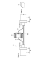
図1に示されるように、第1実施形態に係る光モジュール製造方法により製造された光モジュール1は、例えばCPU(Central Processing Unit)2,3間を接続する光配線に適用される。光モジュール1は、マルチコアファイバ10と、当該マルチコアファイバ10によって接続される2つの光コネクタ(接続部品)20,30と、を備える。マルチコアファイバ10は、複数本によりマルチコアファイバ集合体40として一体的に設けられている。マルチコアファイバ集合体40は、光コネクタ20,30間の光コネクタ20,30に隣接する隣接部分40a,40bにおいて、それぞれブーツ41a,41bにより一体的に保護される。これにより、当該隣接部分40a,40bにおけるマルチコアファイバ10の微小屈曲が防止される。
(First embodiment)
As shown in FIG. 1, the
光コネクタ20,30は、例えばMT(Mechanical Transfer)コネクタであり、マルチコアファイバ10が挿入されるフェルールを有し、当該マルチコアファイバ10の回転方向を固定する機能を有する。光コネクタ20,30のフェルールの内径は、マルチコアファイバ10のガラス部分の外径と同じ大きさに設定される。光コネクタ20は、光モジュール1の一端1aを含む先端部21と、当該先端部21の一端1aと反対側に設けられた根元部22とを有する。
The
先端部21は、CPU2の光コネクタ4の開口部と同じ大きさの端面を有する直方体状であり、光コネクタ20が光コネクタ4と接続される際に、当該開口部から光コネクタ4内に嵌め込まれる部分である。根元部22は、当該開口部より大きい端面を有する直方体状であり、光コネクタ20が光コネクタ4と接続される際に、当該開口部に隣接して光コネクタ4外に配置される部分である。
The
光コネクタ30は、光モジュール1の他端1bを含む先端部31と、当該先端部31の他端1bと反対側に設けられた根元部32とを有する。先端部31は、CPU3の光コネクタ5の開口部と同じ大きさの端面を有する直方体状であり、光コネクタ30が光コネクタ5と接続される際に、当該開口部から光コネクタ5内に嵌め込まれる部分である。根元部32は、当該開口部より大きい端面を有する直方体状であり、光コネクタ30が光コネクタ5と接続される際に、当該開口部に隣接して光コネクタ5外に配置される部分である。
The
本実施形態では、CPU2の光コネクタ4とCPU3の光コネクタ5とは同じ形状であり、光コネクタ20と光コネクタ30とは同じ形状である。また、ブーツ41aとブーツ41bとは同じ形状である。なお、光コネクタ20,30の代わりに、マルチコアファイバ10の回転方向を固定する機能を有する接続部品として、V溝をガラス板で抑える構造、キャピラリ等を用いてもよい。
In this embodiment, the
図2に示されるように、マルチコアファイバ10は、複数のコア11と、コア11の周りを取り囲むジャケット12と、を有する。複数のコア11はファイバ軸方向に延在している。複数のコア11の屈折率はジャケット12の屈折率と異なる。複数のコア11の断面形状は円形である。マルチコアファイバ10のガラス部分の外径はD[mm]である。
As shown in FIG. 2, the
本実施形態に係る光モジュール製造方法は、配置ステップと、配列位置特定ステップと、回転調心ステップと、固定ステップと、切断ステップと、端面研磨ステップと、を備える。ここで、図1〜3を参照して、本実施形態に係る光モジュール製造方法について説明する。 The optical module manufacturing method according to the present embodiment includes an arrangement step, an array position specifying step, a rotation alignment step, a fixing step, a cutting step, and an end surface polishing step. Here, with reference to FIGS. 1-3, the optical module manufacturing method which concerns on this embodiment is demonstrated.
図3に示されるように、配置ステップでは、マルチコアファイバ10の端部を光コネクタ20のフェルールに根元部22側から挿入し、先端部21側から突出させるとともに、マルチコアファイバ10の反対側の端部を光コネクタ30のフェルールに根元部32側から挿入し、先端部31側から突出させる。配置ステップでは、このようにして光コネクタ20,30間を接続するとともに、光コネクタ20,30間外に突出するようにマルチコアファイバ10を光コネクタ30に対して配置する。
As shown in FIG. 3, in the arranging step, the end of the
なお、図3では、光コネクタ20に対しては当該配置ステップから切断ステップまでが既に実施された状態が示されている。以下の説明でも、光コネクタ20に対しては当該配置ステップから切断ステップまでが既に実施されたものとして、主に光コネクタ30に対するマルチコアファイバ10の回転調心について詳述する。
Note that FIG. 3 shows a state where the
配列位置特定ステップまたは回転調心ステップでは、モニタ51を用いることにより、光コネクタ20,30間外であって、光コネクタ30に隣接する側の突出部分10aにおいてマルチコアファイバ10の側面部をマルチコアファイバ10のファイバ軸に垂直な方向から観察し、複数のコア11の配列画像を取り込む。そして、当該配列画像を画像処理することにより、複数のコア11の配列位置を特定し、複数のコア11の配列位置が所定の配列位置と一致するか否かを判定または推定して調心する。
In the arrangement position specifying step or the rotation alignment step, by using the
ここで、本来回転調心したいのは、光コネクタ30の光コネクタ20,30間外側の端面30aにおける複数のコア11の配列位置であることから、端面30aの近傍位置におけるマルチコアファイバ10の側面部を観察する。このとき端面30aから観察位置までの距離をL[mm]とすると、距離Lは100D[mm]以内であることが好ましく、50D[mm]以内であることがより好ましい。なお、一例として、7コアのマルチコアファイバの場合の外径Dが0.15mmであるとした場合には、距離Lは15mm以内、より好ましくは、7.5mm以内となる。
Here, since it is the arrangement position of the plurality of
複数のコア11の配列位置を側面部から観察する方法として、具体的には、マルチコアファイバ10のファイバ軸に垂直な方向においてマルチコアファイバ10に対してモニタ51の反対側に光源53を設置し、当該光源53から出射された光のうちマルチコアファイバ10を透過した光の強度プロファイルを測定する方法を用いることができる。複数のコア11はジャケット12と異なる屈折率を有するため、光源53から出射された光はマルチコアファイバ10の内部で反射、散乱される。これにより、複数のコア11の配列位置に応じた透過光強度プロファイルが得られる。
As a method of observing the arrangement positions of the plurality of
そして、当該透過光強度プロファイルが目的とする透過光強度プロファイルに一致するか否かを特定することにより、複数のコアの配列位置を特定するとともに、配列位置特定ステップを実行する。目的とする透過光強度プロファイルとは、複数のコア11の配列位置が目的とする所定の配列位置と一致する際の透過光強度プロファイルであり、予め求めておくことができる。
Then, by specifying whether or not the transmitted light intensity profile matches the target transmitted light intensity profile, the arrangement positions of the plurality of cores are specified, and the arrangement position specifying step is executed. The target transmitted light intensity profile is a transmitted light intensity profile when the array positions of the plurality of
回転調心ステップでは、把持回転治具52を用いることにより、光コネクタ20,30間外においてマルチコアファイバ10の一部を把持し、配列位置特定ステップの特定結果に基づき、複数のコア11の配列位置が所定の配列位置と一致するように回転調心する。具体的には、上記のように透過光強度プロファイルを測定しながら、当該透過光強度プロファイルが目的とする透過光強度プロファイルと一致するように回転調心する。
In the rotation alignment step, by using the holding
例えば、マルチコアファイバ10のファイバ軸に垂直な断面において、光源53から出射された光の進行方向に垂直な方向に複数のコア11が一次元に並ぶ配列を所定の配列位置とする場合、透過光強度プロファイルの画像処理によって、複数のコア11の間隔が最大となる配列位置を特定し、当該配列位置に回転調心する。なお、図3では、1本のマルチコアファイバ10を回転調心する場合を示しているが、複数のマルチコアファイバ10を回転調心する場合は、配列位置特定ステップおよび回転調心ステップを複数のマルチコアファイバ10に対して一本ずつ行う。
For example, in a cross section perpendicular to the fiber axis of the
固定ステップでは、回転調心ステップにおいて回転調心されたマルチコアファイバ10を光コネクタ30に対して接着により固定する。これにより、光コネクタ30の端面30aに対するマルチコアファイバ10の回転方向を確定させる。なお、接続部材としてV溝を用いる場合は、V溝上部からマルチコアファイバ10を押す押圧力により固定してもよい。
In the fixing step, the
切断ステップでは、突出部分10aを切断する。端面研磨ステップでは、突出部分10aが切断された光コネクタ30の端面30aを研磨する。研磨後の光コネクタ30の端面30aは光モジュール1の他端1bとなる。同様に研磨後の光コネクタ20の光コネクタ20,30間外側の端面20aは光モジュール1の一端1aとなる。これにより、CPU2,3を相互に接続可能な光モジュール1を得ることができる。なお、回転調心の精度を高めるために複数のマルチコアファイバ10に対して一本ずつ固定ステップを行うことが好ましい。
In the cutting step, the protruding
複数のマルチコアファイバ10を含むマルチコアファイバ集合体40は、その外周面を被覆体42により被覆された被覆部分43と、当該被覆体42が除去されて複数の前記マルチコアファイバ10のそれぞれが剥き出しとされた心線部分44と、を有する。心線部分44は、マルチコアファイバ10それぞれが単芯状態とされた単芯部分である。被覆部分43は、例えば、多心のケーブル状態又はコード状態である。したがって、具体的には、配置ステップでは、被覆部分43を光コネクタ20,30間に配置するとともに、心線部分44のそれぞれのマルチコアファイバ10を光コネクタ20,30間外に突出させるようにマルチコアファイバ集合体40を光コネクタ20,30に配置する。したがって、突出部分10aは心線部分44である。なお、ブーツ41a,41b内のマルチコアファイバ10は、ケーブル状態又はコード状態でもよい。
A
また、配列位置特定ステップでは、モニタ51を用いることにより、突出部分10aである心線部分44の側面部を観察し、複数のコア11の配列位置を特定する。更に、回転調心ステップでは、把持回転治具52を用いることにより、突出部分10aである心線部分44を把持し、配列位置特定ステップの特定結果に基づき、複数のコア11の配列位置が所定の配列位置と一致するように回転調心する。マルチコアファイバ集合体40の被覆部分43が多心のケーブル状態の場合は、ルースチューブを用いる等してマルチコアファイバ10がそれぞれケーブル内で自由に回転できる構造とすることが好ましい。
In the array position specifying step, the
以上、本実施形態の光モジュール製造方法によれば、マルチコアファイバ10を光コネクタ20,30間外に突出するように配置し、突出部分10aを観察するとともに、突出部分10aを把持して回転調心する。このように突出部分10aを用いてマルチコアファイバ10を回転調心するので、光コネクタ20,30間の間隔に左右されず、短距離の光配線においてもマルチコアファイバ10の回転調心の精度を高めることができる。したがって、CPU2,3間に限らず、例えば数cm以下の短距離の光配線に好適に用いることができる。また、近年では経済的観点から安価な光トランシーバを複数台並列化し伝送する構成が想定されており、その光伝送路としてマルチコアファイバ10を適用する際にも、本実施形態の光モジュール製造方法による光モジュール1を好適に用いることができる。
As described above, according to the optical module manufacturing method of the present embodiment, the
図4に示されるように、従来技術ではマルチコアファイバ10を光コネクタ20,30間外に突出させないように配置する。そして、マルチコアファイバ10を光コネクタ30に対して回転調心する場合、マルチコアファイバ10のファイバ軸方向からモニタ51により光コネクタ30の端面30aを観察するとともに、光コネクタ20,30間においてマルチコアファイバ10を把持回転治具52により把持し回転調心する。したがって、光コネクタ20,30間には把持回転治具52を挿入できる程度のスペースが必要となる。
As shown in FIG. 4, in the prior art, the
また、把持回転治具52が把持対象とするマルチコアファイバ10以外の他のマルチコアファイバ10に干渉しないように、把持対象のマルチコアファイバ10又は他のマルチコアファイバ10には余長が必要である。図4では、1本のマルチコアファイバ10のみを回転調心する場合を示しているが、他のマルチコアファイバ10を回転調整する場合は、他のマルチコアファイバ10にも余長が必要である。更に、マルチコアファイバ集合体40が、多心のケーブル状態又はコード状態である場合、回転調心するために被覆体42(図3参照)を剥ぐ必要がある。
Further, the
これに対して、本実施形態の光モジュール製造方法によれば、光コネクタ20,30間外の突出部分10aのマルチコアファイバ10を用いて回転調心するので、マルチコアファイバ集合体40が光コネクタ20,30間において被覆体42で被覆されたケーブル状態又はコード状態であっても、この間の被覆体42を剥いだり、被覆体42が剥き出しとされた心線部分44に回転調心のために触れたりする必要がない。したがって、製造される光モジュール1を構成するマルチコアファイバ集合体の機械的信頼性が劣化しにくい。
On the other hand, according to the optical module manufacturing method of the present embodiment, rotation alignment is performed using the
また、本実施形態の光モジュール製造方法によれば、配列位置特定ステップでは、好ましくは、光コネクタ30の光コネクタ20,30間外側の端面30aから100D[mm]以内の位置におけるマルチコアファイバ10の側面部を観察し、より好ましくは、端面30aから50D[mm]以内の位置におけるマルチコアファイバ10の側面部を観察する。これにより、端面30aにおけるマルチコアファイバ10の回転調心状態とほぼ一致した回転調心状態が得られ、回転調心を高精度で行うことができる。
Further, according to the optical module manufacturing method of the present embodiment, in the arrangement position specifying step, the
このようにマルチコアファイバ10のガラス部分の外径Dの大きさに応じて好適な観察位置の範囲が広くなるのは、外径Dの大きさに応じてマルチコアファイバ10の曲げ剛性が大きくなるためである。つまり、外径Dが大きい程、マルチコアファイバ10の曲げ剛性が大きくなるため、観察位置におけるマルチコアファイバ10の回転角度と端面30aにおけるマルチコアファイバ10の回転角度とのずれである回転ずれを小さく抑えることができる。当該回転ずれは、光コネクタ20,30とマルチコアファイバ10とのクリアランス(光コネクタ20,30のフェルールの内径とマルチコアファイバ10のガラス部分の外径Dとの差)に依存する摩擦力によっても影響を受け、例えばクリアランスが大きいと回転ずれが大きくなり易いが、100D[mm]以内であれば当該回転ずれを1°以下とすることができる。
The reason why the range of suitable observation positions becomes wider according to the size of the outer diameter D of the glass portion of the
なお、本実施形態では、突出部分10aはマルチコアファイバ10が剥き出しとされた心線部分44である。この突出部分10aを把持回転治具52で把持する際に、把持する箇所のマルチコアファイバ10の表面を弾性材料により被覆してもよい。これにより、マルチコアファイバ10が把持回転治具52で破断、損傷され難くなる。
In the present embodiment, the protruding
また、接続部材として光コネクタ20,30の代わりにV溝をガラス板で抑える構造を用いる場合、マルチコアファイバ10の端部をフェルールに挿入する必要がないため、V溝で固定する部分についてのみ被覆体42を除去し、突出部分10aについては被覆体42で被覆したままの状態を保つことができる。したがって、マルチコアファイバ10が把持回転治具52で破断、損傷され難くなる。
In addition, when using a structure in which the V-groove is held by a glass plate instead of the
また、図5に示されるように、マルチコアファイバ集合体40として複数のマルチコアファイバ10を一次元に配列させテープ状にまとめたテープ状心線45を有するものとしてもよい。テープ状心線45では心線の順番が固定されるので、心線の管理が容易となり好ましい。更に、テープ状心線45は、間欠的に心線同士が接着されている間欠テープ構造を有することで、回転調心により光コネクタ20,30の根元部22,32側に生じる回転方向の残留応力を解放し易いため好ましい。なお、テープ状心線45は、間欠テープ構造を有するものに限られず、間欠テープ構造を有さないものであってもよい。
Further, as shown in FIG. 5, the
(第2実施形態)
図6および図7に示されるように、第2実施形態に係る光モジュール製造方法は、マルチコアファイバ10が複数のコア11の配列位置に対して所定の位置にマーカ13を有する点で第1実施形態に係る光モジュール製造方法と相違する。マーカ13は複数のコア11およびジャケット12と異なる屈折率を有する。これにより、マーカ13の識別性が向上する。また、マーカ13の設けられる位置をマルチコアファイバ10の外周面に近い位置とすることにより、側面部からのモニタ51による観察が容易となり、且つ外周面から遠い位置とする場合に比べて同じ回転角度でも大きく動くため、配列位置特定ステップにおける配列位置の特定精度が向上する。
(Second Embodiment)
As shown in FIGS. 6 and 7, the optical module manufacturing method according to the second embodiment is the first embodiment in that the
本実施形態の光モジュール製造方法における配列位置特定ステップでは、画像処理によりマーカ13の位置を特定するとともに、当該位置が、複数のコア11の配列位置を所定の配列位置としたときのマーカ13の位置と一致するか否かを特定する。
In the array position specifying step in the optical module manufacturing method of the present embodiment, the position of the
本実施形態によれば、マルチコアファイバ10が複数のコア11の配列位置に対して所定の位置にマーカ13を有することにより、配列位置特定ステップにおける配列位置の特定精度を向上させることができる。この結果、短距離の光配線においてもマルチコアファイバ10の回転調心の精度を一層高めることができる。なお、本実施形態ではマルチコアファイバ10はマーカ13を1つ有するが、2つ以上有してもよい。
According to the present embodiment, the
(第3実施形態)
第3実施形態の光モジュール製造方法は、配置ステップの前に取付けステップ並びに装着固定ステップ、および回転調心ステップ後であって固定ステップ前に仮固定ステップ並びに取外しステップを更に備える点で第1実施形態の光モジュール製造方法と相違する。すなわち、第3実施形態の光モジュール製造方法は、取付けステップと、装着固定ステップと、配置ステップと、配列位置特定ステップと、回転調心ステップと、仮固定ステップと、取外しステップと、固定ステップと、切断ステップと、端面研磨ステップと、を備える。
(Third embodiment)
The optical module manufacturing method according to the third embodiment is a first implementation in that it further includes an attachment step, a mounting and fixing step, and a rotational alignment step before the placement step and a temporary fixing step and a removal step before the fixing step. It is different from the optical module manufacturing method of the embodiment. That is, the optical module manufacturing method of the third embodiment includes an attachment step, a mounting and fixing step, an arrangement step, an arrangement position specifying step, a rotation alignment step, a temporary fixing step, a removal step, and a fixing step. A cutting step and an end surface polishing step.
図8(a)に示されるように、第3実施形態の光モジュール製造方法では、作業台50および接続部品固定治具60を用いる。作業台50は、その上面上にモニタ51および把持回転治具52を具備し、当該上面上で接続部品固定治具60を用いて光モジュール1の製造を行わせるための平板状の台である。なお、作業台50は光源53(図3参照)を更に具備してもよい。
As shown in FIG. 8A, in the optical module manufacturing method of the third embodiment, a work table 50 and a connection
接続部品固定治具60は、図示しない取付け機構により作業台50上に対して取り付けおよび取り外しが可能であるとともに、光コネクタ30に当接して当該光コネクタ30を安定的に固定する当接部61を具備する。また接続部品固定治具60上には、マルチコアファイバ10を光コネクタ30に対して仮固定するクランプ62が一体的に設けられている。当該クランプ62は、マルチコアファイバ10の心線部分44を一本ずつ抑える構造を有することが好ましい。
The connection
取付けステップでは、作業台50の上面上に接続部品固定治具60を図示しない取り付け機構により取り付ける。装着固定ステップでは、上記取付けステップにおいて作業台50に対して取り付けられた接続部品固定治具60に当接部61を利用して光コネクタ30を装着固定する。そして、作業台50および接続部品固定治具60を用いた状態で配置ステップと、配列位置特定ステップと、回転調心ステップとをこの順で実行する。
In the attachment step, the connection
続いて仮固定ステップでは、回転調心ステップで回転調心されたマルチコアファイバ10をクランプ62により光コネクタ30に対して仮固定する。これにより、マルチコアファイバ10の回転調心の角度を保持することができる。ここで、光コネクタ30の光コネクタ20,30間外側の端面30aから150D[mm]以内の位置におけるマルチコアファイバ10をクランプ62で仮固定することが好ましく、100D[mm]以内の位置におけるマルチコアファイバ10をクランプ62で仮固定することがより好ましい。これにより、仮固定後に端面30aにおけるマルチコアファイバ10の回転角度にずれが生じたとしても、そのずれ量が低く抑えられる。
Subsequently, in the temporary fixing step, the
図8(b)に示されるように、取外しステップでは、クランプ62でマルチコアファイバ10を仮固定した状態で光コネクタ30とともに接続部品固定治具60を作業台50から取り外す。そして、固定ステップを実行してからクランプ62による仮固定を解除し、切断ステップおよび端面研磨ステップを実行する。なお、固定ステップ、切断ステップおよび端面研磨ステップを実行してから、クランプ62による仮固定を解除してもよい。
As shown in FIG. 8B, in the removal step, the connection
本実施形態によれば、接続部品固定治具60および接続部品固定治具60に一体的に設けられたクランプ62を用いることで、回転調心ステップ後に光コネクタ30に対するマルチコアファイバ10の回転角度を保持した状態で接続部品固定治具60を取り外すことができる。つまり、回転調心ステップ以前のステップと回転調心ステップより後のステップとを別々に行うことができるので、モニタ51および把持回転治具52といった機材の回転率を向上させるとともに、機材の必要台数を減少させることができる。よって、生産性を向上させるとともに、生産コストを減少させることができる。
According to the present embodiment, the rotation angle of the
また、複数のマルチコアファイバ10はそれぞれ回転調心された状態でクランプ62により仮固定され、固定ステップまで回転調心の角度が保持される。したがって、固定ステップを複数のマルチコアファイバ10に対してまとめて行うことができ、これにより製造効率を高めることができる。なお、クランプ62は、マルチコアファイバ10の心線部分44を複数本同時に抑える構造を有してもよい。
Further, the plurality of
1…光モジュール、10…マルチコアファイバ、11…コア、13…マーカ、20,30…光コネクタ(接続部品)、30a…端面、40…マルチコアファイバ集合体、42…被覆体、43…被覆部分、44…心線部分(単芯部分)、50…作業台、51…モニタ、52…把持回転治具、60…接続部品固定治具、62…クランプ、D…外径。
DESCRIPTION OF
Claims (7)
前記接続部品間を接続するとともに前記接続部品間外に突出するように前記マルチコアファイバを前記接続部品に対して配置する配置ステップと、
前記接続部品間外において前記マルチコアファイバの側面部を観察し、前記複数のコアの配列位置を特定する配列位置特定ステップと、
把持回転治具を用いることにより、前記接続部品間外において前記マルチコアファイバの一部を把持し、前記配列位置特定ステップの特定結果に基づき、前記複数のコアの配列位置が所定の配列位置と一致するように回転調心する回転調心ステップと、
前記回転調心ステップ後に、前記マルチコアファイバを前記接続部品に固定する固定ステップと、
を備える光モジュール製造方法。 A method of manufacturing an optical module comprising a multi-core fiber having a plurality of cores and two connection components connected by the multi-core fiber,
An arrangement step of arranging the multi-core fiber with respect to the connection component so as to connect between the connection components and project outside the connection components;
An arrangement position specifying step of observing a side surface portion of the multi-core fiber outside the connection parts and specifying an arrangement position of the plurality of cores;
By using a gripping rotation jig, a part of the multi-core fiber is gripped between the connection parts, and the array positions of the plurality of cores coincide with a predetermined array position based on the result of specifying the array position specifying step. A rotational alignment step for rotational alignment to
After the rotational alignment step, a fixing step of fixing the multi-core fiber to the connection component;
An optical module manufacturing method comprising:
前記回転調心ステップ後であって前記固定ステップ前に、前記接続部品固定治具に設けられたクランプで前記マルチコアファイバを仮固定する仮固定ステップと、
前記クランプで前記マルチコアファイバを仮固定した状態で前記接続部品とともに前記接続部品固定治具を前記作業台から取り外す取外しステップと、
を備える請求項1または2に記載の光モジュール製造方法。 A mounting and fixing step of mounting and fixing the connection component on a connection component fixing jig attached to a workbench having the gripping rotation jig;
After the rotational alignment step and before the fixing step, a temporary fixing step of temporarily fixing the multi-core fiber with a clamp provided on the connection component fixing jig;
A removal step of removing the connection component fixing jig from the work table together with the connection component in a state where the multi-core fiber is temporarily fixed by the clamp.
An optical module manufacturing method according to claim 1 or 2.
前記配列位置特定ステップでは、画像処理により前記マーカの位置を特定するとともに、当該位置が、前記複数のコアの配列位置を所定の配列位置としたときの前記マーカの位置と一致するか否かを特定する、請求項5に記載の光モジュール製造方法。 The multi-core fiber has a marker at a predetermined position with respect to the arrangement position of the plurality of cores,
In the array position specifying step, the position of the marker is specified by image processing, and whether or not the position matches the position of the marker when the array position of the plurality of cores is a predetermined array position. The optical module manufacturing method according to claim 5, wherein the optical module manufacturing method is specified.
前記マルチコアファイバ集合体は、前記複数のマルチコアファイバの外周面が被覆体により被覆された被覆部分と、前記被覆体が除去されて複数の前記マルチコアファイバそれぞれが単芯状態とされた単芯部分と、を有し、
前記配置ステップでは、前記被覆部分を前記接続部品間に配置するとともに、前記単芯部分のそれぞれの前記マルチコアファイバを前記接続部品間外に突出するように前記接続部品に配置し、
複数の前記マルチコアファイバそれぞれに対し、前記配列位置特定ステップおよび前記回転調心ステップとを行う、請求項1〜6の何れか一項に記載の光モジュール製造方法。
The multi-core fiber is one of a plurality of multi-core fibers included in a multi-core fiber assembly,
The multi-core fiber assembly includes a coated portion in which an outer peripheral surface of the plurality of multi-core fibers is coated with a covering, and a single-core portion in which the covering is removed and each of the plurality of multi-core fibers is in a single-core state. Have
In the arranging step, the covering portion is arranged between the connecting components, and the multi-core fibers of the single core portion are arranged on the connecting components so as to protrude outside the connecting components,
The optical module manufacturing method according to claim 1, wherein the arrangement position specifying step and the rotation alignment step are performed on each of the plurality of multi-core fibers.
Priority Applications (4)
| Application Number | Priority Date | Filing Date | Title |
|---|---|---|---|
| JP2014046100A JP6260362B2 (en) | 2014-03-10 | 2014-03-10 | Optical module manufacturing method |
| PCT/JP2015/056546 WO2015137236A1 (en) | 2014-03-10 | 2015-03-05 | Method for manufacturing optical module |
| CN201580012249.7A CN106068472B (en) | 2014-03-10 | 2015-03-05 | The manufacturing method of optical module |
| US15/097,825 US9759873B2 (en) | 2014-03-10 | 2016-04-13 | Method for manufacturing optical module |
Applications Claiming Priority (1)
| Application Number | Priority Date | Filing Date | Title |
|---|---|---|---|
| JP2014046100A JP6260362B2 (en) | 2014-03-10 | 2014-03-10 | Optical module manufacturing method |
Publications (2)
| Publication Number | Publication Date |
|---|---|
| JP2015169873A true JP2015169873A (en) | 2015-09-28 |
| JP6260362B2 JP6260362B2 (en) | 2018-01-17 |
Family
ID=54071682
Family Applications (1)
| Application Number | Title | Priority Date | Filing Date |
|---|---|---|---|
| JP2014046100A Active JP6260362B2 (en) | 2014-03-10 | 2014-03-10 | Optical module manufacturing method |
Country Status (4)
| Country | Link |
|---|---|
| US (1) | US9759873B2 (en) |
| JP (1) | JP6260362B2 (en) |
| CN (1) | CN106068472B (en) |
| WO (1) | WO2015137236A1 (en) |
Cited By (10)
| Publication number | Priority date | Publication date | Assignee | Title |
|---|---|---|---|---|
| JP2018165804A (en) * | 2017-03-28 | 2018-10-25 | 住友電気工業株式会社 | Method of manufacturing optical connecting component |
| JP2019008198A (en) * | 2017-06-27 | 2019-01-17 | 住友電気工業株式会社 | Method of manufacturing optical connection component, and jig |
| WO2019131441A1 (en) * | 2017-12-27 | 2019-07-04 | 日本電信電話株式会社 | Connection device, optical connector manufacturing device, connection method, and method for manufacturing optical connector |
| JP2019159017A (en) * | 2018-03-09 | 2019-09-19 | Kddi株式会社 | Aligning device of multi-core optical fiber and training data generation device for the same |
| JP2020038255A (en) * | 2018-09-03 | 2020-03-12 | Kddi株式会社 | Core alignment device for fusion of multicore optical fiber and connecting member |
| US11054548B2 (en) | 2017-08-31 | 2021-07-06 | Asahi Kasei Kabushiki Kaisha | Plastic optical fiber, plastic optical fiber cable, connector-attached plastic optical fiber cable, optical communication system, and plastic optical fiber sensor |
| JP2021156761A (en) * | 2020-03-27 | 2021-10-07 | Kddi株式会社 | Measuring device of refractive-index distribution of optical fiber, and processor therefor |
| WO2022138763A1 (en) * | 2020-12-25 | 2022-06-30 | 住友電気工業株式会社 | Method for manufacturing optical fiber connection component |
| WO2022187541A1 (en) * | 2021-03-05 | 2022-09-09 | Commscope Technologies Llc | System and method for multicore fiber evaluation using an overfilled launch |
| WO2023062923A1 (en) * | 2021-10-13 | 2023-04-20 | 株式会社フジクラ | Fiber assembly and method for manufacturing fiber assembly |
Families Citing this family (9)
| Publication number | Priority date | Publication date | Assignee | Title |
|---|---|---|---|---|
| JP6097890B2 (en) * | 2014-08-29 | 2017-03-15 | 古河電気工業株式会社 | Multi-core connector |
| JP2018138910A (en) * | 2017-02-24 | 2018-09-06 | 株式会社フジクラ | Device and method for measuring characteristics of multi-core fiber |
| CN109597178B (en) * | 2017-09-30 | 2021-08-10 | 财团法人金属工业研究发展中心 | Optical alignment equipment and optical alignment method |
| WO2020145010A1 (en) * | 2019-01-08 | 2020-07-16 | 住友電気工業株式会社 | Method for manufacturing optical connector |
| TR201901843A2 (en) * | 2019-02-07 | 2020-08-21 | Ali Osman Oezdogan | INNOVATION IN THE COATING AND MANUFACTURING METHOD OF MULTIPLE CABLE PIPES |
| JP6952728B2 (en) * | 2019-02-14 | 2021-10-20 | 昭和電線ケーブルシステム株式会社 | Intermittent adhesive type optical fiber tape core wire |
| CN111221083B (en) * | 2019-12-09 | 2020-12-11 | 长飞光纤光缆股份有限公司 | Multi-core optical fiber single-core connector and preparation and alignment method thereof |
| CN112255739B (en) * | 2020-11-20 | 2021-08-31 | 长飞光纤光缆股份有限公司 | Multi-core optical fiber connector counter shaft packaging system |
| CN114879307A (en) * | 2022-05-17 | 2022-08-09 | 上海光织科技有限公司 | Multi-core optical fiber bridge fiber and connection method |
Citations (5)
| Publication number | Priority date | Publication date | Assignee | Title |
|---|---|---|---|---|
| JPH0540207A (en) * | 1991-08-05 | 1993-02-19 | Mitsubishi Cable Ind Ltd | Polarization axis adjusting method for optical fiber |
| JP2004246203A (en) * | 2003-02-14 | 2004-09-02 | Matsushita Electric Ind Co Ltd | Method for manufacturing capillary assembly and capillary assembly apparatus |
| JP2013050695A (en) * | 2011-08-01 | 2013-03-14 | Furukawa Electric Co Ltd:The | Method of connecting multi-core fiber, multi-core fiber, and method of manufacturing multi-core fiber |
| JP2013522680A (en) * | 2010-03-16 | 2013-06-13 | オーエフエス ファイテル,エルエルシー | Multi-core fiber connector for multi-core optical fiber cable |
| US20130322835A1 (en) * | 2012-05-31 | 2013-12-05 | Douglas L. Butler | Angular alignment of optical fibers for fiber optic ribbon cables, and related methods |
Family Cites Families (14)
| Publication number | Priority date | Publication date | Assignee | Title |
|---|---|---|---|---|
| FR2701571B1 (en) * | 1993-02-15 | 1995-03-17 | Georges Le Noane | Multicore optical guides of great precision and small dimensions and method of manufacturing these guides. |
| JPH07248434A (en) * | 1994-03-08 | 1995-09-26 | Hitachi Cable Ltd | Optical fiber array and adapter for optical fiber array |
| FR2736441B1 (en) * | 1995-07-04 | 1997-09-26 | Noane Georges Le | DEVICE AND METHOD FOR TRACKING AND CONNECTING MULTI-CORE FIBERS |
| US9366828B2 (en) * | 2010-03-16 | 2016-06-14 | Ofs Fitel, Llc | Systems and techniques for improving insertion loss performance of multicore fiber connectors |
| US9069144B2 (en) | 2010-03-16 | 2015-06-30 | Ofs Fitel, Llc | Connectors for use with polarization-maintaining and multicore optical fiber cables |
| JP6034284B2 (en) * | 2011-03-09 | 2016-11-30 | 古河電気工業株式会社 | Bundle structure manufacturing method, fiber connection structure manufacturing method, fiber connection method, fiber connection structure |
| CN103443679B (en) * | 2011-03-09 | 2015-11-25 | 古河电气工业株式会社 | The core regulating method of optical connector, multi-core fiber and fiber bundle structure and optical fiber arrangement converting member |
| JP2016504620A (en) * | 2012-12-05 | 2016-02-12 | オーエフエス ファイテル,エルエルシー | Structure and technique for aligning multi-core fibers in ferrules or manufacturing jigs |
| US9256033B2 (en) * | 2013-01-23 | 2016-02-09 | Commscope, Inc. Of North Carolina | Cylindrical optical ferrule alignment apparatus |
| WO2014123873A1 (en) * | 2013-02-05 | 2014-08-14 | Commscope, Inc. Of North Carolina | Methods of connectorizing multi-core fiber optic cables and related apparatus |
| US9372304B2 (en) * | 2013-03-28 | 2016-06-21 | Ofs Fitel, Llc | Apparatus for alignment of a multicore fiber in a multifiber connector and method of using same |
| US9213134B2 (en) * | 2013-08-06 | 2015-12-15 | Verizon Patent And Licensing Inc. | Alignment for splicing multi-core optical fibers |
| US9322987B2 (en) * | 2013-08-27 | 2016-04-26 | International Business Machines Corporation | Multicore fiber coupler between multicore fibers and optical waveguides |
| JP5932881B2 (en) * | 2014-05-08 | 2016-06-08 | 株式会社フジクラ | Multi-core fiber and method for producing the multi-core fiber |
-
2014
- 2014-03-10 JP JP2014046100A patent/JP6260362B2/en active Active
-
2015
- 2015-03-05 WO PCT/JP2015/056546 patent/WO2015137236A1/en active Application Filing
- 2015-03-05 CN CN201580012249.7A patent/CN106068472B/en active Active
-
2016
- 2016-04-13 US US15/097,825 patent/US9759873B2/en active Active
Patent Citations (5)
| Publication number | Priority date | Publication date | Assignee | Title |
|---|---|---|---|---|
| JPH0540207A (en) * | 1991-08-05 | 1993-02-19 | Mitsubishi Cable Ind Ltd | Polarization axis adjusting method for optical fiber |
| JP2004246203A (en) * | 2003-02-14 | 2004-09-02 | Matsushita Electric Ind Co Ltd | Method for manufacturing capillary assembly and capillary assembly apparatus |
| JP2013522680A (en) * | 2010-03-16 | 2013-06-13 | オーエフエス ファイテル,エルエルシー | Multi-core fiber connector for multi-core optical fiber cable |
| JP2013050695A (en) * | 2011-08-01 | 2013-03-14 | Furukawa Electric Co Ltd:The | Method of connecting multi-core fiber, multi-core fiber, and method of manufacturing multi-core fiber |
| US20130322835A1 (en) * | 2012-05-31 | 2013-12-05 | Douglas L. Butler | Angular alignment of optical fibers for fiber optic ribbon cables, and related methods |
Cited By (18)
| Publication number | Priority date | Publication date | Assignee | Title |
|---|---|---|---|---|
| JP2018165804A (en) * | 2017-03-28 | 2018-10-25 | 住友電気工業株式会社 | Method of manufacturing optical connecting component |
| JP2019008198A (en) * | 2017-06-27 | 2019-01-17 | 住友電気工業株式会社 | Method of manufacturing optical connection component, and jig |
| US11054548B2 (en) | 2017-08-31 | 2021-07-06 | Asahi Kasei Kabushiki Kaisha | Plastic optical fiber, plastic optical fiber cable, connector-attached plastic optical fiber cable, optical communication system, and plastic optical fiber sensor |
| CN111492282B (en) * | 2017-12-27 | 2022-08-16 | 日本电信电话株式会社 | Connection device, optical connector manufacturing device, connection method, and optical connector manufacturing method |
| JP7067568B2 (en) | 2017-12-27 | 2022-05-16 | 日本電信電話株式会社 | Connection device, optical connector manufacturing device, connection method and optical connector manufacturing method |
| JPWO2019131441A1 (en) * | 2017-12-27 | 2020-07-27 | 日本電信電話株式会社 | Connecting device, optical connector manufacturing device, connecting method, and optical connector manufacturing method |
| CN111492282A (en) * | 2017-12-27 | 2020-08-04 | 日本电信电话株式会社 | Connection device, optical connector manufacturing device, connection method, and optical connector manufacturing method |
| US10955622B2 (en) | 2017-12-27 | 2021-03-23 | Nippon Telegraph And Telephone Corporation | Connection device, optical connector manufacturing device, connection method, and method for manufacturing optical connector |
| WO2019131441A1 (en) * | 2017-12-27 | 2019-07-04 | 日本電信電話株式会社 | Connection device, optical connector manufacturing device, connection method, and method for manufacturing optical connector |
| JP2019159017A (en) * | 2018-03-09 | 2019-09-19 | Kddi株式会社 | Aligning device of multi-core optical fiber and training data generation device for the same |
| JP2020038255A (en) * | 2018-09-03 | 2020-03-12 | Kddi株式会社 | Core alignment device for fusion of multicore optical fiber and connecting member |
| JP7156867B2 (en) | 2018-09-03 | 2022-10-19 | Kddi株式会社 | Alignment device for fusion splicing of multi-core optical fibers |
| JP2021156761A (en) * | 2020-03-27 | 2021-10-07 | Kddi株式会社 | Measuring device of refractive-index distribution of optical fiber, and processor therefor |
| JP7216042B2 (en) | 2020-03-27 | 2023-01-31 | Kddi株式会社 | Optical fiber refractive index distribution measuring device and processing device for the measuring device |
| WO2022138763A1 (en) * | 2020-12-25 | 2022-06-30 | 住友電気工業株式会社 | Method for manufacturing optical fiber connection component |
| WO2022187541A1 (en) * | 2021-03-05 | 2022-09-09 | Commscope Technologies Llc | System and method for multicore fiber evaluation using an overfilled launch |
| WO2023062923A1 (en) * | 2021-10-13 | 2023-04-20 | 株式会社フジクラ | Fiber assembly and method for manufacturing fiber assembly |
| JP7422957B2 (en) | 2021-10-13 | 2024-01-26 | 株式会社フジクラ | Fiber assembly and method for manufacturing fiber assembly |
Also Published As
| Publication number | Publication date |
|---|---|
| US20160223761A1 (en) | 2016-08-04 |
| JP6260362B2 (en) | 2018-01-17 |
| CN106068472B (en) | 2018-07-24 |
| US9759873B2 (en) | 2017-09-12 |
| CN106068472A (en) | 2016-11-02 |
| WO2015137236A1 (en) | 2015-09-17 |
Similar Documents
| Publication | Publication Date | Title |
|---|---|---|
| JP6260362B2 (en) | Optical module manufacturing method | |
| JP5798177B2 (en) | Single core connector for multi-core fiber optic cable | |
| US8858089B2 (en) | Single-fiber connectors for optical fiber cables | |
| EP3734338B1 (en) | Connection device, optical connector manufacturing device, connection method, and method for manufacturing optical connector | |
| JP4866961B2 (en) | Optical collimator, optical connector using the same, and optical collimator holding member | |
| JP2012208236A (en) | Fan-out component for multi-core fiber | |
| CN111221083B (en) | Multi-core optical fiber single-core connector and preparation and alignment method thereof | |
| CN110178063B (en) | Optical fiber holding member, optical connector, and optical coupling structure | |
| WO2012172869A1 (en) | Optical fiber connection method and optical fiber connection structure | |
| WO2013172322A1 (en) | Multicore optical connector, optical connector connection structure | |
| JP2014059479A (en) | Manufacturing method of optical connector, and optical connector | |
| US10031298B2 (en) | Extended access optical fiber connector ferrule | |
| JP3229211U (en) | Optical connection parts | |
| KR20150046603A (en) | integrated optical splitter | |
| JP6124928B2 (en) | Optical fiber connector mounting jig and method of using the same | |
| JP5065340B2 (en) | Optical fiber connector | |
| JP2017167299A (en) | Optical fiber bundle structure and manufacturing method thereof, optical connector, and optical fiber connection structure | |
| JP2015064504A (en) | Core adjustment method of optical fiber and manufacturing method of optical module | |
| EP4270070A1 (en) | Optical fiber ribbon, optical fiber connection component, and method for manufacturing optical fiber connection component | |
| JP2004151296A (en) | Method for connecting optical fiber and connection structure | |
| JP2021063884A (en) | Optical fiber insertion unit and method for building optical fiber insertion unit | |
| JP2022183873A (en) | Optical fiber ribbon | |
| JP2006011254A (en) | Optical connector component and board with the optical connector component and optical transmission apparatus having the board | |
| JP2012159675A (en) | Optical connector | |
| JP2012048262A (en) | Optical collimator, optical connector with optical collimator, and optical collimator holding member |
Legal Events
| Date | Code | Title | Description |
|---|---|---|---|
| A621 | Written request for application examination |
Free format text: JAPANESE INTERMEDIATE CODE: A621 Effective date: 20170216 |
|
| A131 | Notification of reasons for refusal |
Free format text: JAPANESE INTERMEDIATE CODE: A131 Effective date: 20170905 |
|
| A521 | Request for written amendment filed |
Free format text: JAPANESE INTERMEDIATE CODE: A523 Effective date: 20170929 |
|
| TRDD | Decision of grant or rejection written | ||
| A01 | Written decision to grant a patent or to grant a registration (utility model) |
Free format text: JAPANESE INTERMEDIATE CODE: A01 Effective date: 20171114 |
|
| A61 | First payment of annual fees (during grant procedure) |
Free format text: JAPANESE INTERMEDIATE CODE: A61 Effective date: 20171127 |
|
| R150 | Certificate of patent or registration of utility model |
Ref document number: 6260362 Country of ref document: JP Free format text: JAPANESE INTERMEDIATE CODE: R150 |
|
| R250 | Receipt of annual fees |
Free format text: JAPANESE INTERMEDIATE CODE: R250 |
|
| R250 | Receipt of annual fees |
Free format text: JAPANESE INTERMEDIATE CODE: R250 |
|
| R250 | Receipt of annual fees |
Free format text: JAPANESE INTERMEDIATE CODE: R250 |
|
| R250 | Receipt of annual fees |
Free format text: JAPANESE INTERMEDIATE CODE: R250 |