WO2015137236A1 - Method for manufacturing optical module - Google Patents
Method for manufacturing optical module Download PDFInfo
- Publication number
- WO2015137236A1 WO2015137236A1 PCT/JP2015/056546 JP2015056546W WO2015137236A1 WO 2015137236 A1 WO2015137236 A1 WO 2015137236A1 JP 2015056546 W JP2015056546 W JP 2015056546W WO 2015137236 A1 WO2015137236 A1 WO 2015137236A1
- Authority
- WO
- WIPO (PCT)
- Prior art keywords
- optical fiber
- mcf
- core optical
- cores
- optical module
- Prior art date
Links
Images


Classifications
-
- G—PHYSICS
- G02—OPTICS
- G02B—OPTICAL ELEMENTS, SYSTEMS OR APPARATUS
- G02B6/00—Light guides; Structural details of arrangements comprising light guides and other optical elements, e.g. couplings
- G02B6/24—Coupling light guides
- G02B6/36—Mechanical coupling means
- G02B6/38—Mechanical coupling means having fibre to fibre mating means
- G02B6/3807—Dismountable connectors, i.e. comprising plugs
- G02B6/3873—Connectors using guide surfaces for aligning ferrule ends, e.g. tubes, sleeves, V-grooves, rods, pins, balls
- G02B6/3885—Multicore or multichannel optical connectors, i.e. one single ferrule containing more than one fibre, e.g. ribbon type
-
- G—PHYSICS
- G02—OPTICS
- G02B—OPTICAL ELEMENTS, SYSTEMS OR APPARATUS
- G02B6/00—Light guides; Structural details of arrangements comprising light guides and other optical elements, e.g. couplings
- G02B6/02—Optical fibres with cladding with or without a coating
- G02B6/02042—Multicore optical fibres
-
- G—PHYSICS
- G02—OPTICS
- G02B—OPTICAL ELEMENTS, SYSTEMS OR APPARATUS
- G02B6/00—Light guides; Structural details of arrangements comprising light guides and other optical elements, e.g. couplings
- G02B6/24—Coupling light guides
- G02B6/36—Mechanical coupling means
- G02B6/38—Mechanical coupling means having fibre to fibre mating means
- G02B6/3807—Dismountable connectors, i.e. comprising plugs
- G02B6/3833—Details of mounting fibres in ferrules; Assembly methods; Manufacture
- G02B6/3834—Means for centering or aligning the light guide within the ferrule
- G02B6/3843—Means for centering or aligning the light guide within the ferrule with auxiliary facilities for movably aligning or adjusting the fibre within its ferrule, e.g. measuring position or eccentricity
-
- G—PHYSICS
- G02—OPTICS
- G02B—OPTICAL ELEMENTS, SYSTEMS OR APPARATUS
- G02B6/00—Light guides; Structural details of arrangements comprising light guides and other optical elements, e.g. couplings
- G02B6/24—Coupling light guides
- G02B6/36—Mechanical coupling means
- G02B6/38—Mechanical coupling means having fibre to fibre mating means
- G02B6/3807—Dismountable connectors, i.e. comprising plugs
- G02B6/3869—Mounting ferrules to connector body, i.e. plugs
- G02B6/3871—Ferrule rotatable with respect to plug body, e.g. for setting rotational position ; Fixation of ferrules after rotation
-
- G—PHYSICS
- G02—OPTICS
- G02B—OPTICAL ELEMENTS, SYSTEMS OR APPARATUS
- G02B6/00—Light guides; Structural details of arrangements comprising light guides and other optical elements, e.g. couplings
- G02B6/44—Mechanical structures for providing tensile strength and external protection for fibres, e.g. optical transmission cables
- G02B6/4401—Optical cables
- G02B6/4403—Optical cables with ribbon structure
Landscapes
- Physics & Mathematics (AREA)
- General Physics & Mathematics (AREA)
- Optics & Photonics (AREA)
- Mechanical Coupling Of Light Guides (AREA)
- Optical Fibers, Optical Fiber Cores, And Optical Fiber Bundles (AREA)
- Optical Couplings Of Light Guides (AREA)
Abstract
The present embodiment relates to a method for manufacturing an optical module including an MCF and two connection components, and is capable of providing highly accurate rotational alignment for the MCF even in a short distance optical fiber distribution. The MCF is disposed in a space between the two connection components with one end thereof projecting from one connection component. While the arrangement is maintained, the positional arrangement of the projecting end of the cores is observed from the side and adjusted on the basis of the observation results, so that the MCF may be rotationally aligned with a rotary holding jig that holds the projecting end.
Description
本発明は、マルチコア光ファイバ(以下、「MCF」と記す)の端部にコネクタが配置された光モジュールを製造する光モジュール製造方法に関するものである。
The present invention relates to an optical module manufacturing method for manufacturing an optical module in which a connector is arranged at an end of a multi-core optical fiber (hereinafter referred to as “MCF”).
近年のデータセンターやハイパフォーマンスコンピュータでは、膨大な情報量を処理する必要性から、伝送速度の向上、伝送容量の増大を目的とした通信配線の光配線化が進んでいる。特に、従来は電気配線であったCPU-CPU間のような短距離区間を光配線に置き換える要求が高まっている。ここで、複数の伝送チャネルを高密度、省スペースで提供できる伝送媒体として、MCFを光配線に適用することが期待されている。MCFは複数のコアを有する。そのため、MCFの端部にコネクタを配置する場合は、これら複数のコアの配列位置を所定の配列位置とするためにMCFの高精度な回転調心(MCFの長手方向を中心とした円周方向に、当該MCFを回転させる)が要求される。
In recent data centers and high performance computers, communication wiring has been increasingly used for the purpose of improving transmission speed and increasing transmission capacity due to the necessity of processing a huge amount of information. In particular, there is an increasing demand for replacing a short distance section between a CPU and a CPU, which has conventionally been an electrical wiring, with an optical wiring. Here, MCF is expected to be applied to optical wiring as a transmission medium that can provide a plurality of transmission channels with high density and space saving. The MCF has a plurality of cores. Therefore, when a connector is arranged at the end of the MCF, the MCF has a highly accurate rotational alignment (circumferential direction centered on the longitudinal direction of the MCF) in order to set the arrangement position of the plurality of cores to a predetermined arrangement position. , The MCF is rotated).
特許文献1には、MCFを、その外周面の一部に平坦部を形成することで非円形状の断面を有するように加工し、当該平坦部を利用してMCFを回転調心する技術が開示されている。また、一般に知られている技術としては、コネクタの一方側から把持回転治具を用いてMCFを把持するとともに該コネクタの他方側からMCFの端面を観察しながら、把持されたMCFを回転調心する技術がある。
Patent Document 1 discloses a technique in which an MCF is processed to have a non-circular cross section by forming a flat portion on a part of its outer peripheral surface, and the MCF is rotationally aligned using the flat portion. It is disclosed. Further, as a generally known technique, the MCF is gripped from one side of the connector using a gripping rotation jig, and the gripped MCF is rotationally aligned while observing the end face of the MCF from the other side of the connector. There is technology to do.
発明者らは上述の従来技術について検討した結果、以下の課題を発見した。すなわち、上記特許文献1の技術では、回転調心の精度を高めるためにはMCFにおける断面内のコアと平坦部との相対位置の製造精度を極めて高くする必要がある。また、上記の一般に知られている技術は、MCFの両端部にコネクタを配置する場合にコネクタ同士の間隔を把持回転治具が挿入できる間隔以上に設定する必要があり、短距離の光配線には適さない。
The inventors have found the following problems as a result of examining the above-described conventional technology. That is, in the technique of Patent Document 1, it is necessary to increase the manufacturing accuracy of the relative position between the core and the flat portion in the cross section of the MCF in order to increase the accuracy of rotational alignment. Further, in the above-described generally known technique, when the connectors are arranged at both ends of the MCF, it is necessary to set the interval between the connectors to be equal to or greater than the interval at which the gripping rotation jig can be inserted. Is not suitable.
本発明は、上記課題を解決するためになされたものであり、短距離の光配線においてもMCFの回転調心の精度を高めることができる光モジュール製造方法を提供することを目的とする。
The present invention has been made to solve the above-described problems, and an object of the present invention is to provide an optical module manufacturing method capable of improving the accuracy of MCF rotational alignment even in a short-distance optical wiring.
本実施形態に係る光モジュール製造方法は、複数のコアを有するMCF(マルチコア光ファイバ)と、当該MCFに取り付けられた第1および第2接続部品と、を備える光モジュールを製造する方法であって、配置ステップと、配列位置特定ステップと、回転調心ステップと、固定ステップとを少なくとも備える。配置ステップは、互いに離間している第1および第2接続部品に対してMCFを配置するステップであって、当該配置ステップでは、第1接続部品とマルチコア光ファイバの位置関係に関して、第2接続部品に対面する第1端面と第1端面に対向する第2端面を有する第1接続部品に対して、第1接続部品の第2端面から第2接続部品とは反対側にその一部が突出するように、MCFが配置される。配列位置特定ステップでは、第1接続部品の第2端面から第2接続部品とは反対側に突出した、MCFの突出部の側面観察により、複数のコアの配列位置が特定される。回転調心ステップでは、把持回転治具を用いることにより、MCFの突出部が把持され、配列位置特定ステップの特定結果に基づき、複数のコアの配列位置が所定の配列位置と一致するように、MCFが回転調心される。固定ステップは、回転調心ステップ後のステップであって、当該固定ステップでは、MCFが第1および第2接続部品それぞれに固定される。
An optical module manufacturing method according to the present embodiment is a method of manufacturing an optical module including an MCF (multi-core optical fiber) having a plurality of cores, and first and second connection components attached to the MCF. , An arrangement step, an arrangement position specifying step, a rotation alignment step, and a fixing step. The arranging step is a step of arranging the MCF with respect to the first and second connecting components that are separated from each other, and in the arranging step, the second connecting component is related to the positional relationship between the first connecting component and the multicore optical fiber. Part of the first connecting part protrudes from the second end face of the first connecting part to the side opposite to the second connecting part with respect to the first connecting part having the first end face facing the first end face and the second end face facing the first end face. Thus, the MCF is arranged. In the arrangement position specifying step, the arrangement positions of the plurality of cores are specified by observing a side surface of the protruding portion of the MCF that protrudes from the second end face of the first connection part to the side opposite to the second connection part. In the rotation alignment step, by using the gripping rotation jig, the protruding portion of the MCF is gripped, and based on the identification result of the array position specifying step, the array positions of the plurality of cores match the predetermined array position. The MCF is rotationally aligned. The fixing step is a step after the rotational alignment step, and in this fixing step, the MCF is fixed to each of the first and second connecting components.
本実施形態によれば、短距離の光配線においてもMCFの回転調心の精度を高めることができる光モジュール製造方法を提供することができる。
According to the present embodiment, it is possible to provide an optical module manufacturing method capable of increasing the accuracy of MCF rotational alignment even in a short-distance optical wiring.
[本願発明の実施形態の説明]
最初に本願発明の実施態様を列記して説明する。 [Description of Embodiment of Present Invention]
First, embodiments of the present invention will be listed and described.
最初に本願発明の実施態様を列記して説明する。 [Description of Embodiment of Present Invention]
First, embodiments of the present invention will be listed and described.
(1)本実施形態に係る光モジュール製造方法は、複数のコアを有するMCF(マルチコア光ファイバ)と、当該MCFによって接続される2つの接続部品と、を備える光モジュールを製造する方法である。すなわち、当該光モジュール製造方法は、上記MCFと、所定距離だけ離間した状態で、MCFに取り付けられた2つの接続部品と、を備える光モジュールを製造する。当該光モジュール製造方法は、第1の態様として、接続部品間を接続するとともに接続部品間外に突出するようにMCFを接続部品に対して配置する配置ステップと、接続部品間外においてMCFの側面部を観察し、複数のコアの配列位置を特定する配列位置特定ステップと、把持回転治具を用いることにより、接続部品間外においてMCFの一部を把持し、配列位置特定ステップの特定結果に基づき、複数のコアの配列位置が所定の配列位置と一致するように回転調心する回転調心ステップと、回転調心ステップ後に、MCFを接続部品に固定する固定ステップと、を備える。
(1) The optical module manufacturing method according to the present embodiment is a method of manufacturing an optical module including an MCF (multi-core optical fiber) having a plurality of cores and two connection components connected by the MCF. That is, the optical module manufacturing method manufactures an optical module including the MCF and two connection components attached to the MCF in a state of being separated by a predetermined distance. In the optical module manufacturing method, as a first aspect, the connecting step of connecting the connecting parts and arranging the MCF with respect to the connecting parts so as to protrude outside the connecting parts, and the side surface of the MCF outside the connecting parts A part of the MCF is gripped between the connected parts by using an array position specifying step for observing the part and specifying the array position of a plurality of cores and a gripping rotation jig. Based on the rotation alignment step, rotation alignment is performed so that the arrangement positions of the plurality of cores coincide with the predetermined arrangement position, and a fixing step of fixing the MCF to the connection component after the rotation alignment step.
上記「回転調心」とは、MCFの断面(MCFの長手方向に直交する面)において、ファイバ軸(当該MCFの長手方向に沿って伸びる軸であって、当該MCFの断面上の中心を通過する軸)を中心として円周方向に当該MCFを回転させることにより、断面上における複数のコアの配列位置を所望の位置まで回転させる動作を意味する。また、上記2つの接続部品の一方を第1接続部品、他方を第2接続部品とそれぞれ規定すると、上記「接続部品間」とは、第1および第2接続部品によって挟まれた領域であって、MCFが実質的な余長部分を設けることなく配置された該MCFの配置領域を意味する。また、「接続部品間外」とは、MCFの長手方向に沿って接続部品間を挟む領域を意味し、例えば、第1接続部品を基準にするとき、第1および第2接続部品で挟まれた領域とは反対側の領域であって、第2接続部品とは反対側に該第1接続部品から突出した、MCFの一部(突出部)が存在する領域を意味する。したがって、互いに離間している第1および第2接続部品に対してMCFを配置する配置ステップでは、第1接続部品とMCFの位置関係に関して、第2接続部品に対面する第1端面と第1端面に対向する第2端面を有する第1接続部品に対して、該第1接続部品の第2端面から第2接続部品とは反対側にその一部が突出するように、MCFが配置される。また、配列位置特定ステップでは、第1接続部品の第2端面から第2接続部品とは反対側に突出した、MCFの突出部の側面観察により、複数のコアの配列位置が特定される。回転調心ステップでは、把持回転治具を用いることにより、MCFの突出部が把持され、配列位置特定ステップの特定結果に基づき、複数のコアの配列位置が所定の配列位置と一致するように、MCFが回転調心される。回転調心ステップ後の固定ステップでは、MCFが第1および第2接続部品それぞれに固定される。したがって、本実施形態では、突出部の側面観察と、把持回転治具による突出部の把持は、何れも第1接続部品に対して第2接続部品とは逆側(第1および第2接続部品で挟まれた領域外)で行われる。
The “rotational alignment” is a fiber axis (an axis extending along the longitudinal direction of the MCF) in the cross section of the MCF (a plane perpendicular to the longitudinal direction of the MCF) and passes through the center of the MCF on the cross section. This means an operation of rotating the arrangement position of the plurality of cores on the cross section to a desired position by rotating the MCF in the circumferential direction around the axis). If one of the two connection components is defined as a first connection component and the other is defined as a second connection component, the “between connection components” is an area sandwiched between the first and second connection components. , MCF means an arrangement area of the MCF arranged without providing a substantial extra length portion. Further, “outside the connection parts” means a region sandwiching the connection parts along the longitudinal direction of the MCF. For example, when the first connection part is used as a reference, the connection part is sandwiched between the first and second connection parts. This is a region on the opposite side to the region where the part of the MCF (protruding portion) that protrudes from the first connecting component on the side opposite to the second connecting component is present. Therefore, in the arrangement step of arranging the MCF with respect to the first and second connection parts that are separated from each other, the first end face and the first end face that face the second connection part with respect to the positional relationship between the first connection part and the MCF. The MCF is disposed so that a part of the first connection component having the second end surface facing the first connection component protrudes from the second end surface of the first connection component to the opposite side of the second connection component. Further, in the arrangement position specifying step, the arrangement positions of the plurality of cores are specified by observing the side surface of the protruding portion of the MCF protruding from the second end face of the first connection part to the side opposite to the second connection part. In the rotation alignment step, by using the gripping rotation jig, the protruding portion of the MCF is gripped, and based on the identification result of the array position specifying step, the array positions of the plurality of cores match the predetermined array position. The MCF is rotationally aligned. In the fixing step after the rotational alignment step, the MCF is fixed to each of the first and second connection components. Therefore, in this embodiment, the side observation of the protruding portion and the gripping of the protruding portion by the holding rotation jig are both opposite to the second connecting component with respect to the first connecting component (the first and second connecting components). Outside the area sandwiched between).
(2)上記第1の態様に適用可能な第2の態様として、配列位置特定ステップでは、MCFのガラス部分の外径をD[mm]としたとき、第1接続部品の第2端面(接続部品間外の端面)から100×D[mm]以内の位置において、MCFの突出部の側面が観察される。
(2) As a second aspect applicable to the first aspect, in the arrangement position specifying step, when the outer diameter of the glass portion of the MCF is D [mm], the second end face (connection) of the first connection component The side surface of the protrusion of the MCF is observed at a position within 100 × D [mm] from the end surface outside the part).
(3)上記第1および第2の態様のうち少なくとも何れかの態様に適用可能な第3の態様として、当該光モジュール製造方法は、回転調心ステップ後かつ固定ステップ前に行われる仮固定ステップを備えてもよい。この仮固定ステップでは、MCFのガラス部分の外径をD[mm]としたとき、第1接続部品の第2端面(接続部品間外の端面)から150×D[mm]以内の位置において、MCFの突出部分がクランプで仮固定される。
(3) As a third aspect applicable to at least one of the first and second aspects, the optical module manufacturing method includes a temporary fixing step performed after the rotation alignment step and before the fixing step. May be provided. In this temporary fixing step, when the outer diameter of the glass portion of the MCF is D [mm], at a position within 150 × D [mm] from the second end surface of the first connection component (end surface outside the connection component), The protruding part of the MCF is temporarily fixed with a clamp.
(4)上記第1および第2の態様のうち少なくとも何れかの態様に適用可能な第4の態様として、当該光モジュール製造方法は、回転調心ステップ前に行われる装着固定ステップと、回転調心ステップ後かつ固定ステップ前に行われる仮固定ステップと、仮固定ステップ後かつ記固定ステップ前に行われる取外しステップと、を備えてもよい。装着固定ステップでは、把持回転治具を具備する作業台に対して取り付けられた接続部品固定治具に対して第1接続部品を装着することにより、該第1接続部品の位置が固定される。仮固定ステップでは、接続部品固定治具に設けられたクランプでMCFの突出部分が仮固定される。取外しステップでは、クランプでMCFを仮固定した状態で第1接続部品とともに接続部品固定治具が作業台から取り外される。
(4) As a fourth aspect applicable to at least one of the first and second aspects, the optical module manufacturing method includes a mounting fixing step performed before the rotation alignment step, a rotation adjustment step, and a rotation adjustment step. A temporary fixing step performed after the center step and before the fixing step, and a removal step performed after the temporary fixing step and before the fixing step may be provided. In the mounting and fixing step, the position of the first connecting component is fixed by mounting the first connecting component to the connecting component fixing jig attached to the work table having the gripping and rotating jig. In the temporary fixing step, the protruding portion of the MCF is temporarily fixed by a clamp provided on the connection component fixing jig. In the removal step, the connection component fixing jig is removed from the work table together with the first connection component in a state where the MCF is temporarily fixed by the clamp.
(5)上記第1~第4の態様のうち少なくとも何れかの態様に適用可能な第5の態様として、回転調心ステップでは、MCFの突出部分の側面を撮像することにより得られた複数のコアの配列画像に基づいて、該複数のコアの配列位置が所定の配列位置と一致するか否かが判定される。
(5) As a fifth aspect applicable to at least one of the first to fourth aspects, in the rotational alignment step, a plurality of images obtained by imaging the side surface of the protruding portion of the MCF Based on the array image of the cores, it is determined whether or not the array positions of the plurality of cores match a predetermined array position.
(6)上記第5の態様に適用可能な第6の態様として、MCFは、複数のコアの配列位置に対して所定の位置関係を満たすよう配置されたマーカを有してもよい。この場合、配列位置特定ステップでは、配列画像に基づいて特定されたマーカの位置が、複数のコアの配列位置を所定の配列位置に回転調心したときの位置と一致するか否かが判定される。
(6) As a sixth aspect applicable to the fifth aspect, the MCF may have a marker arranged so as to satisfy a predetermined positional relationship with respect to the arrangement positions of the plurality of cores. In this case, in the array position specifying step, it is determined whether or not the position of the marker specified based on the array image matches the position when the array positions of the plurality of cores are rotationally aligned to the predetermined array position. The
(7)上記第1~第6の態様のうち少なくとも何れかの態様に適用可能な第7の態様として、上記MCFは、マルチコア光ファイバ集合体(以下、「MCF集合体」と記す)に含まれる複数のマルチコア光ファイバ要素の1本であってもよい。この場合、MCF集合体は、複数のMCF要素それぞれの外周面が被覆体により被覆された被覆部分と、被覆体の一部が除去されることにより複数のマルチコア光ファイバ要素それぞれが分離状態とされた分離部分と、を有する。配置ステップでは、被覆部分が第1および第2接続部品の間に配置されるとともに、分離部分が第1接続部品の第2端面から第2接続部品とは反対側に突出するように、第1および第2接続部品に対してMCF集合体が配置される。また、当該光モジュール製造方法では、複数のMCF要素それぞれに対し、配列位置特定ステップおよび回転調心ステップが行われる。
(7) As a seventh aspect applicable to at least one of the first to sixth aspects, the MCF is included in a multi-core optical fiber assembly (hereinafter referred to as “MCF assembly”). One of a plurality of multi-core optical fiber elements may be used. In this case, in the MCF aggregate, the outer peripheral surface of each of the plurality of MCF elements is covered with the covering, and a part of the covering is removed so that the plurality of multi-core optical fiber elements are separated from each other. And a separating portion. In the arranging step, the first portion is arranged such that the covering portion is arranged between the first and second connecting parts, and the separating portion protrudes from the second end surface of the first connecting part to the side opposite to the second connecting part. The MCF assembly is disposed with respect to the second connection component. In the optical module manufacturing method, the arrangement position specifying step and the rotation alignment step are performed for each of the plurality of MCF elements.
[本願発明の実施形態の詳細]
以下、本実施形態に係る光モジュール製造方法の具体的な構造を、添付図面を参照しながら詳細に説明する。なお、本発明はこれらの例示に限定されるものではなく、特許請求の範囲によって示され、特許請求の範囲と均等の意味および範囲内での全ての変更が含まれることが意図される。 [Details of the embodiment of the present invention]
Hereinafter, a specific structure of the optical module manufacturing method according to the present embodiment will be described in detail with reference to the accompanying drawings. In addition, this invention is not limited to these illustrations, is shown by the claim, and intends that all the changes within the meaning and range equivalent to a claim are included.
(第1実施形態)
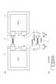
図1(a)に示されたように、第1実施形態に係る光モジュール製造方法により製造された光モジュール1は、例えばCPU(Central Processing Unit)2,3間を接続する光配線に適用される。光モジュール1は、1または複数のMCF10と、当該MCF10を介して接続される2つの光コネクタ(接続部品)20,30と、を備える。図1(a)の例では、被覆体(一体化用被覆)により一体化されたMCF集合体40として、複数のMCF10が開示されている。なお、2つの光コネクタ20,30の間には、1本のMCF10が配置されてもよい。MCF集合体40は、光コネクタ20,30間の、光コネクタ20,30に隣接する隣接部分40a,40bにおいて、それぞれブーツ41a,41b(図1(b)参照)により一体的に保護される。これにより、当該隣接部分40a,40bにおける各MCF10の微小屈曲が防止される。 (First embodiment)
As shown in FIG. 1A, theoptical module 1 manufactured by the optical module manufacturing method according to the first embodiment is applied to, for example, an optical wiring that connects between CPUs (Central Processing Units) 2 and 3. The The optical module 1 includes one or a plurality of MCFs 10 and two optical connectors (connection components) 20 and 30 connected via the MCF 10. In the example of FIG. 1A, a plurality of MCFs 10 are disclosed as the MCF aggregate 40 integrated by a covering (coating for integration). A single MCF 10 may be disposed between the two optical connectors 20 and 30. The MCF assembly 40 is integrally protected by boots 41a and 41b (see FIG. 1B) at adjacent portions 40a and 40b adjacent to the optical connectors 20 and 30 between the optical connectors 20 and 30, respectively. Thereby, the micro bending of each MCF10 in the said adjacent parts 40a and 40b is prevented.
図1(a)に示されたように、第1実施形態に係る光モジュール製造方法により製造された光モジュール1は、例えばCPU(Central Processing Unit)2,3間を接続する光配線に適用される。光モジュール1は、1または複数のMCF10と、当該MCF10を介して接続される2つの光コネクタ(接続部品)20,30と、を備える。図1(a)の例では、被覆体(一体化用被覆)により一体化されたMCF集合体40として、複数のMCF10が開示されている。なお、2つの光コネクタ20,30の間には、1本のMCF10が配置されてもよい。MCF集合体40は、光コネクタ20,30間の、光コネクタ20,30に隣接する隣接部分40a,40bにおいて、それぞれブーツ41a,41b(図1(b)参照)により一体的に保護される。これにより、当該隣接部分40a,40bにおける各MCF10の微小屈曲が防止される。 (First embodiment)
As shown in FIG. 1A, the
光コネクタ20,30は、例えばMT(Mechanical Transfer)コネクタであり、MCF10のそれぞれが挿入されるフェルールを有し、各MCF10の回転方向(ファイバ軸AXを中心とした円周方向)を固定する機能を有する。光コネクタ20,30の各フェルールの内径は、各MCF10のガラス部分の外径と略同じ大きさに設定される。光コネクタ20は、光モジュール1の一端1aを含む先端部21と、当該先端部21の一端1aとは反対側に設けられた根元部22とを有する。
The optical connectors 20 and 30 are, for example, MT (Mechanical Transfer) connectors, each having a ferrule into which each MCF 10 is inserted, and a function of fixing the rotation direction of each MCF 10 (circumferential direction around the fiber axis AX). Have The inner diameter of each ferrule of the optical connectors 20 and 30 is set to be approximately the same as the outer diameter of the glass portion of each MCF 10. The optical connector 20 includes a distal end portion 21 including one end 1 a of the optical module 1 and a root portion 22 provided on the opposite side to the one end 1 a of the distal end portion 21.
先端部21は、直方体形状を有するとともに、CPU2の光コネクタ4の開口部と略同じ大きさの端面を有する。この先端部21は、光コネクタ20が光コネクタ4と接続される際に、該開口部から光コネクタ4内に嵌め込まれる部分である。根元部22も、直方体形状を有するとともに、光コネクタ4の開口部より大きい端面を有する。この根元部33は、光コネクタ20が光コネクタ4と接続される際に、該開口部に隣接して光コネクタ4外に配置される部分である。
The front end portion 21 has a rectangular parallelepiped shape and an end surface having substantially the same size as the opening portion of the optical connector 4 of the CPU 2. The tip 21 is a portion that is fitted into the optical connector 4 from the opening when the optical connector 20 is connected to the optical connector 4. The root portion 22 also has a rectangular parallelepiped shape and an end face larger than the opening of the optical connector 4. The root portion 33 is a portion disposed outside the optical connector 4 adjacent to the opening when the optical connector 20 is connected to the optical connector 4.
光コネクタ30は、光モジュール1の他端1bを含む先端部31と、当該先端部31の他端1bと反対側に設けられた根元部32とを有する。先端部31は、直方体形状を有するとともに、CPU3の光コネクタ5の開口部と略同じ大きさの端面を有する。この先端部31は、光コネクタ30が光コネクタ5と接続される際に、該開口部から光コネクタ5内に嵌め込まれる部分である。根元部32も、直方体形状を有するとともに、光コネクタ5の開口部より大きい端面を有する。根元部32は、光コネクタ30が光コネクタ5と接続される際に、該開口部に隣接して光コネクタ5外に配置される部分である。
The optical connector 30 has a distal end portion 31 including the other end 1b of the optical module 1 and a root portion 32 provided on the opposite side of the other end 1b of the distal end portion 31. The distal end portion 31 has a rectangular parallelepiped shape, and has an end surface that is substantially the same size as the opening of the optical connector 5 of the CPU 3. The tip portion 31 is a portion that is fitted into the optical connector 5 from the opening when the optical connector 30 is connected to the optical connector 5. The root portion 32 also has a rectangular parallelepiped shape and an end face larger than the opening of the optical connector 5. The base portion 32 is a portion that is disposed outside the optical connector 5 adjacent to the opening when the optical connector 30 is connected to the optical connector 5.
本実施形態では、CPU2の光コネクタ4とCPU3の光コネクタ5とは同じ形状を有し、光コネクタ20と光コネクタ30とは同じ形状を有する。また、ブーツ41aとブーツ41bとは同じ形状を有する。なお、光コネクタ20,30の代わりに、各MCF10の回転方向を固定する機能を有する接続部品として、V溝をガラス板で抑える構造、キャピラリ等が利用されてもよい。
In this embodiment, the optical connector 4 of the CPU 2 and the optical connector 5 of the CPU 3 have the same shape, and the optical connector 20 and the optical connector 30 have the same shape. The boot 41a and the boot 41b have the same shape. Instead of the optical connectors 20 and 30, as a connection part having a function of fixing the rotation direction of each MCF 10, a structure in which the V groove is held by a glass plate, a capillary, or the like may be used.
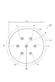
図2に示されたように、MCF10のそれぞれは、複数のコア11と、各コア11の周りを取り囲むジャケット12と、で構成されたガラス部分と、ガラス部分の外周面に設けられた、紫外線硬化樹脂等のファイバ被覆15を有する。なお、各MCF10のファイバ軸AXは、当該MCF10の断面中心を通り、当該MCFの長手方向に沿って延びる軸である。また、各MCF10において、複数のコア11はファイバ軸AX方向に延在している。複数のコア11それぞれの屈折率はジャケット12の屈折率と異なる。複数のコア11それぞれの断面形状は円形である。各MCF10のガラス部分の外径はD[mm]である。
As shown in FIG. 2, each of the MCFs 10 includes a glass portion composed of a plurality of cores 11 and a jacket 12 surrounding each core 11, and an ultraviolet ray provided on the outer peripheral surface of the glass portion. It has a fiber coating 15 such as a cured resin. The fiber axis AX of each MCF 10 is an axis that passes through the center of the cross section of the MCF 10 and extends along the longitudinal direction of the MCF. In each MCF 10, the plurality of cores 11 extend in the fiber axis AX direction. The refractive index of each of the plurality of cores 11 is different from the refractive index of the jacket 12. The cross-sectional shape of each of the plurality of cores 11 is a circle. The outer diameter of the glass portion of each MCF 10 is D [mm].
本実施形態に係る光モジュール製造方法は、配置ステップと、配列位置特定ステップと、回転調心ステップと、固定ステップと、切断ステップと、端面研磨ステップと、を備える。ここで、図1~3を参照して、本実施形態に係る光モジュール製造方法について説明する。
The optical module manufacturing method according to the present embodiment includes an arrangement step, an arrangement position specifying step, a rotation alignment step, a fixing step, a cutting step, and an end surface polishing step. Here, the optical module manufacturing method according to the present embodiment will be described with reference to FIGS.
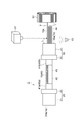
図3に示されたように、配置ステップでは、各MCF10の端部が、先端部21側から突出した状態になるまで、光コネクタ20の対応するフェルールに、根元部22側から挿入される。一方、各MCF10の反対側の端部は、先端部31側から突出した状態になるまで、光コネクタ30の対応するフェルールに、根元部32側から挿入される。配置ステップでは、このようにして光コネクタ20,30が、複数のMCF10を介して接続されるとともに、光コネクタ20,30間外(接続部品間外)にその一部(突出部分10a)が突出するように、複数のMCF10が光コネクタ30に対してそれぞれ配置される。
As shown in FIG. 3, in the placement step, the end portion of each MCF 10 is inserted from the root portion 22 side into the corresponding ferrule of the optical connector 20 until the end portion protrudes from the tip portion 21 side. On the other hand, the opposite end portion of each MCF 10 is inserted from the root portion 32 side into the corresponding ferrule of the optical connector 30 until it protrudes from the distal end portion 31 side. In the arrangement step, the optical connectors 20 and 30 are connected through the plurality of MCFs 10 in this way, and a part (protruding portion 10a) protrudes between the optical connectors 20 and 30 (outside the connection parts). As described above, the plurality of MCFs 10 are respectively arranged with respect to the optical connector 30.
なお、図3では、光コネクタ20に対しては当該配置ステップから切断ステップまでが既に実施された状態が示されている。以下の説明でも、光コネクタ20に対しては当該配置ステップから切断ステップまでが既に実施されたものとして、主に光コネクタ30に対する各MCF10の回転調心について詳述する。
Note that FIG. 3 shows a state where the optical connector 20 has already been performed from the placement step to the cutting step. In the following description, the rotation alignment of each MCF 10 with respect to the optical connector 30 will be mainly described in detail, assuming that the steps from the placement step to the cutting step have already been performed for the optical connector 20.
配列位置特定ステップまたは回転調心ステップでは、モニタ51を用いることにより、各MCF10における複数のコア11の配列画像が取り込まれる。すなわち、光コネクタ20,30間外であって、光コネクタ30に隣接する側に位置する各MCF10の突出部分10aの側面部が、当該MCF10のファイバ軸AXに垂直な方向からモニタ51により撮像される。そして、当該配列画像を画像処理することにより、各MCF10に関して、複数のコア11の配列位置が特定され、複数のコア11の配列位置が所定の配列位置と一致するか否かが判定または推定された後、当該MCF10の回転調心が行われる。
In the array position specifying step or the rotation alignment step, the array images of the plurality of cores 11 in each MCF 10 are captured by using the monitor 51. That is, the side surface portion of the protruding portion 10a of each MCF 10 located outside the optical connectors 20 and 30 and adjacent to the optical connector 30 is imaged by the monitor 51 from the direction perpendicular to the fiber axis AX of the MCF 10. The Then, by performing image processing on the array image, the array positions of the plurality of cores 11 are specified for each MCF 10, and it is determined or estimated whether or not the array positions of the plurality of cores 11 match a predetermined array position. After that, the rotational alignment of the MCF 10 is performed.
ここで、各MCF10に関して、本来回転調心の対象は、光コネクタ30の光コネクタ20,30間外側の端面30aにおける複数のコア11の配列位置である。このことから、端面30aの近傍位置における各MCF10の側面部(突出部分10aの側面部)が観察される。このとき端面30aから観察位置までの距離をL[mm]とすると、距離Lは100×D[mm]以内であることが好ましく、50×D[mm]以内であることがより好ましい。なお、一例として、7コアのMCFの場合の外径Dが0.15mmであるとした場合には、距離Lは15mm以内、より好ましくは、7.5mm以内となる。
Here, with respect to each MCF 10, the target of rotation alignment is the arrangement position of the plurality of cores 11 on the end face 30a on the outer side between the optical connectors 20 and 30 of the optical connector 30. From this, the side surface portion of each MCF 10 (side surface portion of the protruding portion 10a) in the vicinity of the end surface 30a is observed. At this time, when the distance from the end face 30a to the observation position is L [mm], the distance L is preferably within 100 × D [mm], and more preferably within 50 × D [mm]. As an example, when the outer diameter D in the case of a 7-core MCF is 0.15 mm, the distance L is within 15 mm, more preferably within 7.5 mm.
各MCF10における複数のコア11の配列位置を当該MCF10の側面部から観察する方法として、具体的には、各MCF10のファイバ軸AXに垂直な方向に沿って、各MCF10に対してモニタ51の反対側に光源53を設置し、当該光源53から出射された光のうち各MCF10を透過した光の強度プロファイルを測定する方法を用いることができる。各MCF10において、複数のコア11はジャケット12と異なる屈折率を有するため、光源53から出射された光はMCF10の内部で反射、散乱される。これにより、各MCF10における複数のコア11の配列位置に応じた透過光強度プロファイルが得られる。
As a method of observing the arrangement position of the plurality of cores 11 in each MCF 10 from the side surface portion of the MCF 10, specifically, the monitor 51 is opposite to each MCF 10 along the direction perpendicular to the fiber axis AX of each MCF 10. A method can be used in which a light source 53 is installed on the side and an intensity profile of light transmitted through each MCF 10 among light emitted from the light source 53 is measured. In each MCF 10, the plurality of cores 11 have a refractive index different from that of the jacket 12, so that the light emitted from the light source 53 is reflected and scattered inside the MCF 10. Thereby, the transmitted light intensity profile according to the arrangement position of the some core 11 in each MCF10 is obtained.
そして、各MCF10に関して、当該透過光強度プロファイルが目的とする透過光強度プロファイルに一致するか否かを判定することにより、複数のコア11の配列位置を特定する配列位置特定ステップが実行される。目的とする透過光強度プロファイルとは、各MCF10における複数のコア11の配列位置が目的とする所定の配列位置と一致する際の透過光強度プロファイルであり、予め求めておくことができる。
Then, for each MCF 10, by determining whether or not the transmitted light intensity profile matches the intended transmitted light intensity profile, an array position specifying step for specifying the array positions of the plurality of cores 11 is executed. The target transmitted light intensity profile is a transmitted light intensity profile when the array positions of the plurality of cores 11 in each MCF 10 coincide with a predetermined target array position, and can be obtained in advance.
回転調心ステップでは、把持回転治具52を用いることにより、光コネクタ20,30間外において各MCF10の一部が把持され、配列位置特定ステップの特定結果に基づき、把持されたMCF10における複数のコア11の配列位置が所定の配列位置と一致するように当該MCF10の回転調心が行われる。具体的には、上記のように透過光強度プロファイルを測定しながら、当該透過光強度プロファイルが目的とする透過光強度プロファイルと一致するように各MCF10の回転調心が行われる。
In the rotational alignment step, a part of each MCF 10 is gripped between the optical connectors 20 and 30 by using the gripping rotation jig 52, and a plurality of gripped MCFs 10 in the gripped MCF 10 are determined based on the result of specifying the array position specifying step. The rotation alignment of the MCF 10 is performed so that the arrangement position of the cores 11 coincides with the predetermined arrangement position. Specifically, while measuring the transmitted light intensity profile as described above, each MCF 10 is rotationally aligned so that the transmitted light intensity profile matches the intended transmitted light intensity profile.
例えば、各MCF10に関して、そのファイバ軸AXに垂直な断面において光源53から出射された光の進行方向に垂直な方向に複数のコア11が一次元に並ぶ配列を所定の配列位置とする場合、透過光強度プロファイルの画像処理によって、複数のコア11の間隔が最大となる配列位置を特定し、複数のコア11の配列位置が特定された配列位置に一致するように回転調心が行われる。なお、図3では、1本のMCF10を回転調心する場合が示されているが、複数のMCF10を回転調心する場合、配列位置特定ステップおよび回転調心ステップは、上述のように、複数のMCF10に対して一本ずつ行われる。
For example, when each MCF 10 has a predetermined arrangement position in which a plurality of cores 11 are arranged one-dimensionally in a direction perpendicular to the traveling direction of light emitted from the light source 53 in a cross section perpendicular to the fiber axis AX, transmission is performed. By the image processing of the light intensity profile, an array position where the interval between the plurality of cores 11 is maximized is specified, and rotational alignment is performed so that the array positions of the plurality of cores 11 coincide with the specified array position. Note that FIG. 3 shows a case where one MCF 10 is rotationally aligned. However, when a plurality of MCFs 10 are rotationally aligned, the arrangement position specifying step and the rotational alignment step are performed as described above. This is performed one by one for each MCF 10.
固定ステップでは、回転調心ステップにおいてそれぞれ回転調心されたMCF10が、光コネクタ30に対して接着により固定される。これにより、光コネクタ30の端面30aに対する各MCF10の回転方向が確定される。なお、接続部材としてV溝を用いる場合、MCF10のそれぞれは、V溝上部から当該MCF10のそれぞれを押す押圧力により固定されてもよい。
In the fixing step, the MCFs 10 that have been rotationally aligned in the rotational alignment step are fixed to the optical connector 30 by adhesion. Thereby, the rotation direction of each MCF 10 with respect to the end face 30a of the optical connector 30 is determined. In addition, when using V groove as a connection member, each of MCF10 may be fixed by the pressing force which presses each of the said MCF10 from V groove upper part.
切断ステップでは、各MCF10の突出部分10aが切断される。端面研磨ステップでは、各MCF10の突出部分10aが切断された光コネクタ30の端面30aが研磨される。研磨後の光コネクタ30の端面30aは、光モジュール1の他端1bとなる。同様に、研磨後の光コネクタ20の、光コネクタ20,30間外側の端面20aは、光モジュール1の一端1aとなる。これにより、CPU2,3を相互に接続可能な光モジュール1を得ることができる。なお、回転調心の精度を高めるため、固定ステップは、複数のMCF10に対して一本ずつ行われるのが好ましい。
In the cutting step, the protruding portion 10a of each MCF 10 is cut. In the end surface polishing step, the end surface 30a of the optical connector 30 from which the protruding portion 10a of each MCF 10 is cut is polished. The end face 30 a of the optical connector 30 after polishing becomes the other end 1 b of the optical module 1. Similarly, the end face 20 a on the outer side between the optical connectors 20 and 30 of the polished optical connector 20 becomes one end 1 a of the optical module 1. Thereby, the optical module 1 which can connect CPU2 and 3 mutually can be obtained. In order to improve the accuracy of rotational alignment, the fixing step is preferably performed one by one for the plurality of MCFs 10.
複数のMCF(MCF要素)10を含むMCF集合体40は、その外周面を被覆体(一体化用被覆)42により被覆された被覆部分43と、当該被覆体42が除去されて複数のMCF10のそれぞれが剥き出しとされた心線部分(coated-fiber part)44と、を有する。なお、心線部分44における各MCF10は、図2に示すようにガラス部分の外周面上にファイバ被覆15が設けられた心線状態である。また、心線部分44は、複数のMCF10のそれぞれが分離状態(単芯状態:single-fiber state)とされた分離部分(単芯部分:single-fiber part)である。被覆部分43は、例えば、多心のケーブル状態又はコード状態である。したがって、具体的に配置ステップでは、被覆部分43を光コネクタ20,30間に配置するとともに、心線部分44におけるMCF10のそれぞれを光コネクタ20,30間外に突出させるように、MCF集合体40が光コネクタ20,30間に配置される。したがって、MCF10それぞれの突出部分10aが心線部分44を構成している。なお、ブーツ41a,41b内における複数のMCF10は、ケーブル状態又はコード状態でもよい。
The MCF assembly 40 including a plurality of MCFs (MCF elements) 10 includes a covering portion 43 whose outer peripheral surface is covered by a covering (coating for integration) 42, and the covering 42 is removed to form a plurality of MCFs 10. Each of which has a coated-fiber part 44 exposed. Each MCF 10 in the core portion 44 is in a core state in which the fiber coating 15 is provided on the outer peripheral surface of the glass portion as shown in FIG. The core portion 44 is a separated portion (single-fiber portion) in which each of the plurality of MCFs 10 is in a separated state (single-fiber state). The covering portion 43 is, for example, a multi-core cable state or a cord state. Therefore, specifically, in the arranging step, the covering portion 43 is arranged between the optical connectors 20 and 30, and the MCF assembly 40 is arranged so that each of the MCFs 10 in the core portion 44 protrudes outside the optical connectors 20 and 30. Is disposed between the optical connectors 20 and 30. Accordingly, the protruding portion 10 a of each MCF 10 constitutes the core wire portion 44. The plurality of MCFs 10 in the boots 41a and 41b may be in a cable state or a cord state.
また、配列位置特定ステップでは、モニタ51を用いることにより、心線部分44における突出部分10aの側面部がそれぞれ観察され、各突出部分10aにおける複数のコア11の配列位置が特定される。更に、回転調心ステップでは、把持回転治具52を用いることにより、心線部分44における突出部分10aが把持され、配列位置特定ステップの特定結果に基づき、該把持された突出部分10aにおける複数のコア11の配列位置が所定の配列位置と一致するように回転調心が行われる。MCF集合体40の被覆部分43が多心のケーブル状態の場合、当該MCF集合体40は、ルースチューブを用いる等により複数のMCF10がそれぞれケーブル内で自由に回転できる構造を有するのが好ましい。
Further, in the arrangement position specifying step, by using the monitor 51, the side portions of the protruding portion 10a in the core wire portion 44 are observed, and the arrangement positions of the plurality of cores 11 in each protruding portion 10a are specified. Further, in the rotational alignment step, the protruding portion 10a in the core wire portion 44 is gripped by using the gripping rotation jig 52, and a plurality of the protruding portions 10a in the gripped protruding portion 10a are determined based on the identification result of the arrangement position specifying step. Rotation alignment is performed so that the arrangement position of the cores 11 matches a predetermined arrangement position. When the covering portion 43 of the MCF assembly 40 is in a multi-core cable state, the MCF assembly 40 preferably has a structure in which the plurality of MCFs 10 can freely rotate within the cable by using a loose tube, for example.
以上、本実施形態の光モジュール製造方法によれば、複数のMCF10のそれぞれに関して、その一部(突出部分10a)が光コネクタ20,30間外にそれぞれ突出するように当該MCF10を配置した状態で、突出部分10aが観察され、該観察された突出部分10aを把持した状態で回転調心が行われる。このように把持された突出部分10aを用いて回転調心が行われるので、光コネクタ20,30間の間隔に左右されず、短距離の光配線においても各MCF10の回転調心の精度を高めることができる。したがって、本実施形態は、CPU2,3間に限らず、例えば数cm以下の短距離の光配線に好適に用いることができる。また、近年では経済的観点から安価な光トランシーバを複数台並列化した状態で光伝送を行う構成が想定されており、その光伝送路として1または複数のMCF10を適用する際にも、本実施形態の光モジュール製造方法による光モジュール1を好適に用いることができる。
As described above, according to the optical module manufacturing method of the present embodiment, with respect to each of the plurality of MCFs 10, in a state where the MCFs 10 are arranged so that a part (the protruding portion 10 a) protrudes between the optical connectors 20 and 30. The protruding portion 10a is observed, and rotational alignment is performed in a state where the observed protruding portion 10a is gripped. Since the rotation alignment is performed using the protruding portion 10a thus gripped, the accuracy of the rotation alignment of each MCF 10 is improved even in a short-distance optical wiring regardless of the distance between the optical connectors 20 and 30. be able to. Therefore, this embodiment can be suitably used not only between the CPUs 2 and 3 but also for short-distance optical wiring of, for example, several cm or less. Further, in recent years, from an economical point of view, a configuration in which optical transmission is performed in a state where a plurality of inexpensive optical transceivers are arranged in parallel is assumed, and this implementation is also performed when one or a plurality of MCFs 10 are applied as the optical transmission path. The optical module 1 according to the optical module manufacturing method of the embodiment can be suitably used.
図4に示されたように、従来技術では、複数のMCF10が光コネクタ20,30間外に突出させないように配置される。そして、光コネクタ30に対して各MCF10の回転調心が行われる場合、まず、各MCF10のファイバ軸AX方向からモニタ51により光コネクタ30の端面30aが観察される。そして、光コネクタ20,30間においてMCF10のそれぞれが把持回転治具52により個別に把持された状態で回転調心が行われる。したがって、従来技術では、光コネクタ20,30間には把持回転治具52を挿入できる程度のスペースが必要となる。
As shown in FIG. 4, in the conventional technique, a plurality of MCFs 10 are arranged so as not to protrude between the optical connectors 20 and 30. When the rotation alignment of each MCF 10 is performed with respect to the optical connector 30, first, the end face 30 a of the optical connector 30 is observed by the monitor 51 from the fiber axis AX direction of each MCF 10. Then, rotation alignment is performed in a state where each of the MCFs 10 is individually gripped by the gripping rotation jig 52 between the optical connectors 20 and 30. Therefore, in the prior art, a space is required between the optical connectors 20 and 30 so that the gripping rotation jig 52 can be inserted.
また、把持回転治具52が把持対象とするMCF10以外の他のMCF10に干渉しないように、把持対象のMCF10または他のMCF10には余長が必要である。図4の例では、1本のMCF10のみが回転調心される場合が示されているが、他のMCF10を回転調整する場合は、他のMCF10にも余長が必要である。更に、MCF集合体40が、多心のケーブル状態又はコード状態である場合、回転調心するために被覆体42(図3参照)を剥ぐ必要がある。
Also, the MCF 10 to be gripped or the other MCF 10 needs an extra length so that the gripping rotation jig 52 does not interfere with other MCFs 10 other than the MCF 10 to be gripped. In the example of FIG. 4, the case where only one MCF 10 is rotationally aligned is shown. However, when other MCFs 10 are rotationally adjusted, the other MCFs 10 need extra lengths. Further, when the MCF assembly 40 is in a multi-core cable state or a cord state, it is necessary to peel off the covering body 42 (see FIG. 3) for rotational alignment.
これに対して、本実施形態の光モジュール製造方法によれば、光コネクタ20,30間外に位置する各MCF10の突出部分10aを用いて当該MCF10の回転調心が行われる。そのため、MCF集合体40が光コネクタ20,30間において被覆体42で被覆されたケーブル状態またはコード状態であっても、光コネクタ20,30間の被覆体42が剥がされたり、被覆体42が剥き出しとされた心線部分44において、ある突出部分10aの回転調心のために他の突出部分10aに触れられたりする必要がない。したがって、製造される光モジュール1を構成するMCF集合体40の機械的信頼性が劣化しにくい。
On the other hand, according to the optical module manufacturing method of the present embodiment, rotation alignment of the MCF 10 is performed using the protruding portions 10a of the MCFs 10 positioned outside the optical connectors 20 and 30. Therefore, even if the MCF assembly 40 is in a cable state or a cord state in which the MCF assembly 40 is covered with the covering 42 between the optical connectors 20 and 30, the covering 42 between the optical connectors 20 and 30 is peeled off or the covering 42 is In the exposed core portion 44, there is no need to touch another protruding portion 10a for rotational alignment of one protruding portion 10a. Therefore, the mechanical reliability of the MCF assembly 40 that constitutes the manufactured optical module 1 is unlikely to deteriorate.
また、本実施形態の光モジュール製造方法によれば、配列位置特定ステップでは、好ましくは、光コネクタ30の光コネクタ20,30間外側の端面30aから100×D[mm]以内の位置における各MCF10の側面部(突出部分10aの側面部)が観察され、より好ましくは、端面30aから50×D[mm]以内の位置における各MCF10の側面部が観察される。これにより、端面30aにおけるMCF10の回転調心状態とほぼ一致した回転調心状態が観察でき、回転調心を高精度で行うことができる。
Further, according to the optical module manufacturing method of the present embodiment, in the array position specifying step, each MCF 10 is preferably located at a position within 100 × D [mm] from the outer end surface 30a between the optical connectors 20 and 30 of the optical connector 30. Side surfaces (side portions of the protruding portion 10a) are observed, and more preferably, the side portions of each MCF 10 are observed at a position within 50 × D [mm] from the end surface 30a. Thereby, the rotational alignment state substantially coincident with the rotational alignment state of the MCF 10 on the end face 30a can be observed, and the rotational alignment can be performed with high accuracy.
このように各MCF10のガラス部分の外径Dの大きさに応じて好適な観察位置の範囲が広くなるのは、外径Dの大きさに応じて当該MCF10の曲げ剛性が大きくなるためである。つまり、外径Dが大きい程、各MCF10の曲げ剛性が大きくなるため、観察位置における各MCF10の回転角度と端面30aにおける各MCF10の回転角度とのずれである回転ずれを小さく抑えることができる。このように回転ずれは、光コネクタ20,30における各MCF10とのクリアランス(光コネクタ20,30それぞれにおける各フェルールの内径と各MCF10のガラス部分の外径Dとの差)に依存する摩擦力によっても影響を受け、例えばクリアランスが大きいと回転ずれが大きくなり易いが、100×D[mm]以内であれば当該回転ずれを1°以下とすることができる。
The reason why the range of suitable observation positions becomes wider according to the size of the outer diameter D of the glass portion of each MCF 10 in this way is because the bending rigidity of the MCF 10 becomes larger according to the size of the outer diameter D. . That is, since the bending rigidity of each MCF 10 increases as the outer diameter D increases, the rotational deviation that is the deviation between the rotational angle of each MCF 10 at the observation position and the rotational angle of each MCF 10 at the end face 30a can be suppressed to a small value. As described above, the rotational deviation is caused by a frictional force depending on the clearance between each optical connector 20 and 30 and each MCF 10 (difference between the inner diameter of each ferrule and the outer diameter D of the glass portion of each MCF 10). For example, if the clearance is large, the rotational deviation is likely to increase. However, if the clearance is within 100 × D [mm], the rotational deviation can be 1 ° or less.
なお、本実施形態では、各突出部分10aは、当該MCF10が剥き出しとされた心線部分44である。この突出部分10aを把持回転治具52で把持する際に、把持する箇所の当該MCF10の表面が弾性材料により被覆されてもよい。これにより、各MCF10が把持回転治具52で破断、損傷され難くなる。
In the present embodiment, each protruding portion 10a is a core portion 44 from which the MCF 10 is exposed. When the protruding portion 10a is gripped by the gripping rotation jig 52, the surface of the MCF 10 at the gripping portion may be covered with an elastic material. Accordingly, each MCF 10 is not easily broken or damaged by the gripping rotation jig 52.
また、接続部材として光コネクタ20,30の代わりにV溝をガラス板で抑える構造を用いる場合、各MCF10の端部はフェルールに挿入される必要がない。この場合、V溝で固定される部分についてのみ被覆体42が除去され、各MCF10の突出部分10aについては被覆体42で覆われたままの状態を保つことができる。したがって、この場合も各MCF10が把持回転治具52で破断、損傷され難くなる。
Further, when a structure in which the V-groove is held by a glass plate instead of the optical connectors 20 and 30 as the connection member, the end of each MCF 10 does not need to be inserted into the ferrule. In this case, the covering 42 is removed only for the portion fixed by the V-groove, and the protruding portion 10a of each MCF 10 can be kept covered with the covering 42. Therefore, also in this case, each MCF 10 is not easily broken or damaged by the gripping rotation jig 52.
また、図5に示されたように、MCF集合体40として、複数のMCF10を一次元に配列させた状態でこれらMCF10をテープ状にまとめたテープ状心線45が採用されてもよい。テープ状心線45では、心線の順番が固定されるので、心線の管理が容易となり好ましい。更に、テープ状心線45は、間欠的に心線同士(隣接するMCF10のファイバ被覆同士)が接着されている間欠テープ構造を有する。この場合、回転調心により光コネクタ20,30の根元部22,32側に生じる回転方向の残留応力を解放し易いため好ましい。なお、テープ状心線45は、間欠テープ構造を有するものに限られず、間欠テープ構造を有さないものであってもよい。
Further, as shown in FIG. 5, a tape-shaped core wire 45 in which a plurality of MCFs 10 are arranged in a one-dimensional manner and the MCFs 10 are arranged in a tape shape may be adopted as the MCF aggregate 40. The tape-shaped core wire 45 is preferable because the order of the core wires is fixed, so that the management of the core wires becomes easy. Furthermore, the tape-shaped core wire 45 has an intermittent tape structure in which the core wires are intermittently bonded to each other (fiber coverings of adjacent MCFs 10). This is preferable because it is easy to release the residual stress in the rotation direction generated on the base portions 22 and 32 side of the optical connectors 20 and 30 by the rotation alignment. The tape-shaped core wire 45 is not limited to one having an intermittent tape structure, and may be one having no intermittent tape structure.
(第2実施形態)
図6および図7に示されたように、第2実施形態に係る光モジュール製造方法は、各MCF10(図6)が複数のコア11の配列位置に対して所定の位置にマーカ13を有する点で第1実施形態に係る光モジュール製造方法と相違する。マーカ13は複数のコア11およびジャケット12と異なる屈折率を有する。これにより、マーカ13の識別性が向上する。また、マーカ13の設けられる位置を各MCF10の外周面に近い位置とすることにより、側面部からのモニタ51による観察が容易となり、且つ外周面から遠い位置とする場合に比べて同じ回転角度でも大きく動くため、配列位置特定ステップにおける配列位置の特定精度が向上する。なお、図7には、光コネクタ30側の構成として、図3と同様の構成が示されているが、本実施形態における光コネクタ20側の構成も図3と同様の構成である。 (Second Embodiment)
As shown in FIGS. 6 and 7, in the optical module manufacturing method according to the second embodiment, each MCF 10 (FIG. 6) has amarker 13 at a predetermined position with respect to the arrangement position of the plurality of cores 11. This is different from the optical module manufacturing method according to the first embodiment. The marker 13 has a refractive index different from that of the plurality of cores 11 and the jacket 12. Thereby, the discriminability of the marker 13 is improved. Further, by making the position where the marker 13 is provided close to the outer peripheral surface of each MCF 10, observation by the monitor 51 from the side surface portion is facilitated, and even at the same rotation angle as compared with the case where the position is far from the outer peripheral surface. Since it moves greatly, the accuracy of specifying the array position in the array position specifying step is improved. 7 shows the same configuration as that in FIG. 3 as the configuration on the optical connector 30 side, the configuration on the optical connector 20 side in this embodiment is also the same as that in FIG.
図6および図7に示されたように、第2実施形態に係る光モジュール製造方法は、各MCF10(図6)が複数のコア11の配列位置に対して所定の位置にマーカ13を有する点で第1実施形態に係る光モジュール製造方法と相違する。マーカ13は複数のコア11およびジャケット12と異なる屈折率を有する。これにより、マーカ13の識別性が向上する。また、マーカ13の設けられる位置を各MCF10の外周面に近い位置とすることにより、側面部からのモニタ51による観察が容易となり、且つ外周面から遠い位置とする場合に比べて同じ回転角度でも大きく動くため、配列位置特定ステップにおける配列位置の特定精度が向上する。なお、図7には、光コネクタ30側の構成として、図3と同様の構成が示されているが、本実施形態における光コネクタ20側の構成も図3と同様の構成である。 (Second Embodiment)
As shown in FIGS. 6 and 7, in the optical module manufacturing method according to the second embodiment, each MCF 10 (FIG. 6) has a
本実施形態の光モジュール製造方法における配列位置特定ステップでは、各MCF10に関して、画像処理によりマーカ13の位置が特定されるとともに、当該マーカ13の位置が、複数のコア11の配列位置を所定の配列位置としたときのマーカ13の位置と一致するか否かが判定される。
In the arrangement position specifying step in the optical module manufacturing method of the present embodiment, the position of the marker 13 is specified by image processing for each MCF 10, and the position of the marker 13 is the predetermined arrangement of the arrangement positions of the plurality of cores 11. It is determined whether or not the position of the marker 13 coincides with the position.
本実施形態によれば、各MCF10が複数のコア11の配列位置に対して所定の位置にマーカ13を有することにより(図6)、配列位置特定ステップにおける配列位置の特定精度を向上させることができる。この結果、短距離の光配線においても各MCF10の回転調心の精度を一層高めることができる。なお、本実施形態では、各MCF10はマーカ13を1つ有するが、2つ以上有してもよい。
According to this embodiment, each MCF 10 has the marker 13 at a predetermined position with respect to the array positions of the plurality of cores 11 (FIG. 6), thereby improving the array position specifying accuracy in the array position specifying step. it can. As a result, the accuracy of rotational alignment of each MCF 10 can be further improved even in a short-distance optical wiring. In the present embodiment, each MCF 10 has one marker 13, but may have two or more.
(第3実施形態)
第3実施形態の光モジュール製造方法は、配置ステップの前に取付けステップ並びに装着固定ステップ、および回転調心ステップ後であって固定ステップ前に仮固定ステップ並びに取外しステップを更に備える点で第1実施形態の光モジュール製造方法と相違する。すなわち、第3実施形態の光モジュール製造方法は、取付けステップと、装着固定ステップと、配置ステップと、配列位置特定ステップと、回転調心ステップと、仮固定ステップと、取外しステップと、固定ステップと、切断ステップと、端面研磨ステップと、を備える。 (Third embodiment)
The optical module manufacturing method according to the third embodiment is a first implementation in that it further includes an attachment step, a mounting and fixing step, and a rotational alignment step before the placement step and a temporary fixing step and a removal step before the fixing step. It is different from the optical module manufacturing method of the embodiment. That is, the optical module manufacturing method of the third embodiment includes an attachment step, a mounting and fixing step, an arrangement step, an arrangement position specifying step, a rotation alignment step, a temporary fixing step, a removal step, and a fixing step. A cutting step and an end surface polishing step.
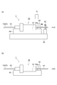
図8(a)に示されたように、第3実施形態の光モジュール製造方法では、作業台50および接続部品固定治具60が用いられる。作業台50は、その上面上にモニタ51および把持回転治具52を具備し、当該上面上で接続部品固定治具60を用いて光モジュール1の製造を行わせるための平板状の台である。なお、作業台50は光源53(図3参照)を更に具備してもよい。
As shown in FIG. 8A, in the optical module manufacturing method of the third embodiment, a work table 50 and a connection component fixing jig 60 are used. The work table 50 includes a monitor 51 and a gripping rotation jig 52 on its upper surface, and is a flat table for allowing the optical module 1 to be manufactured using the connection component fixing jig 60 on the upper surface. . The work table 50 may further include a light source 53 (see FIG. 3).
接続部品固定治具60は、図示しない取付け機構により作業台50上に対して取り付けおよび取り外しが可能であるとともに、光コネクタ30に当接して当該光コネクタ30を安定的に固定する当接部61を具備する。また接続部品固定治具60上には、各MCF10を光コネクタ30に対して仮固定するクランプ62が一体的に設けられている。当該クランプ62は、心線部分44における各MCF10の突出部分10aを一本ずつ抑える構造を有することが好ましい。
The connection component fixing jig 60 can be attached to and detached from the work table 50 by an attachment mechanism (not shown), and a contact portion 61 that contacts the optical connector 30 and stably fixes the optical connector 30. It comprises. A clamp 62 for temporarily fixing each MCF 10 to the optical connector 30 is integrally provided on the connection component fixing jig 60. The clamp 62 preferably has a structure that suppresses one protruding portion 10a of each MCF 10 in the core wire portion 44 one by one.
取付けステップでは、作業台50の上面上に、接続部品固定治具60が図示しない取り付け機構により取り付けられる。装着固定ステップでは、上記取付けステップにおいて作業台50に対して取り付けられた接続部品固定治具60に当接部61を利用して、光コネクタ30が装着固定される。そして、作業台50および接続部品固定治具60を用いた状態で、配置ステップ、配列位置特定ステップ、回転調心ステップの順に、これらステップが実行される。
In the mounting step, the connection component fixing jig 60 is mounted on the upper surface of the work table 50 by a mounting mechanism (not shown). In the mounting and fixing step, the optical connector 30 is mounted and fixed using the contact portion 61 to the connection component fixing jig 60 mounted to the work table 50 in the mounting step. Then, in a state where the work table 50 and the connection component fixing jig 60 are used, these steps are executed in the order of the arrangement step, the arrangement position specifying step, and the rotation alignment step.
続いて仮固定ステップでは、回転調心ステップで回転調心された各MCF10がクランプ62により光コネクタ30に対して仮固定される。これにより、MCF10の回転調心の角度が保持可能になる。ここで、光コネクタ30の、光コネクタ20,30間外側の端面30aから150×D[mm]以内の位置において各MCF10がクランプ62で仮固定されることが好ましく、100×D[mm]以内の位置において各MCF10がクランプ62で仮固定されることがより好ましい。これにより、仮固定後に端面30aにおけるMCF10の何れかの回転角度にずれが生じたとしても、そのずれ量が低く抑えられる。
Subsequently, in the temporary fixing step, each MCF 10 that has been rotationally aligned in the rotational alignment step is temporarily fixed to the optical connector 30 by the clamp 62. Thereby, the rotation alignment angle of the MCF 10 can be maintained. Here, it is preferable that each MCF 10 is temporarily fixed by the clamp 62 at a position within 150 × D [mm] from the outer end face 30a between the optical connectors 20 and 30 of the optical connector 30, and within 100 × D [mm]. It is more preferable that each MCF 10 is temporarily fixed by the clamp 62 at the position. As a result, even if a deviation occurs in any rotation angle of the MCF 10 on the end face 30a after temporary fixing, the deviation amount is kept low.
図8(b)に示されたように、取外しステップでは、クランプ62でMCF10を仮固定した状態で、光コネクタ30とともに接続部品固定治具60が作業台50から取り外される。そして、固定ステップ後にクランプ62による仮固定が解除され、切断ステップおよび端面研磨ステップが実行される。なお、固定ステップ、切断ステップおよび端面研磨ステップが実行された後、クランプ62による仮固定が解除されてもよい。
As shown in FIG. 8B, in the removal step, the connecting component fixing jig 60 is removed from the work table 50 together with the optical connector 30 in a state where the MCF 10 is temporarily fixed by the clamp 62. Then, the temporary fixing by the clamp 62 is released after the fixing step, and the cutting step and the end surface polishing step are executed. Note that the temporary fixing by the clamp 62 may be released after the fixing step, the cutting step, and the end surface polishing step are performed.
本実施形態によれば、接続部品固定治具60および接続部品固定治具60に一体的に設けられたクランプ62が用いられる。これにより、回転調心ステップ後に光コネクタ30に対する各MCF10の回転角度を保持した状態で、接続部品固定治具60の取り外しが可能になる。つまり、回転調心ステップ以前のステップと回転調心ステップより後のステップとを別々に行うことができるので、モニタ51および把持回転治具52といった機材の回転率を向上させるとともに、機材の必要台数を減少させることができる。よって、生産性を向上させるとともに、生産コストを減少させることができる。
According to the present embodiment, the connection component fixing jig 60 and the clamp 62 provided integrally with the connection component fixing jig 60 are used. Thereby, the connection component fixing jig 60 can be removed in a state where the rotation angle of each MCF 10 with respect to the optical connector 30 is maintained after the rotation alignment step. That is, since the steps before the rotation alignment step and the steps after the rotation alignment step can be performed separately, the rotation rate of the equipment such as the monitor 51 and the gripping rotation jig 52 is improved, and the necessary number of equipment is required. Can be reduced. Therefore, productivity can be improved and production cost can be reduced.
なお、クランプ62は、心線部分44における複数のMCF10の突出部分10aを同時に抑える構造を有してもよい。この場合、複数のMCF10はそれぞれ回転調心された状態でクランプ62により仮固定され、固定ステップまで回転調心の角度が保持される。したがって、固定ステップを複数のMCF10に対してまとめて行うことができ、これにより製造効率を高めることができる。
The clamp 62 may have a structure that simultaneously suppresses the protruding portions 10 a of the plurality of MCFs 10 in the core wire portion 44. In this case, the plurality of MCFs 10 are temporarily fixed by the clamps 62 while being rotationally aligned, and the rotational alignment angle is maintained until the fixing step. Therefore, the fixing step can be performed collectively on the plurality of MCFs 10, thereby improving the manufacturing efficiency.
1…光モジュール、10…MCF(マルチコア光ファイバ)、11…コア、13…マーカ、20,30…光コネクタ(接続部品)、30a…端面、40…MCF集合体(マルチコア光ファイバ集合体)、42…被覆体、43…被覆部分、44…心線部分(単芯部分、分離部分)、50…作業台、51…モニタ、52…把持回転治具、60…接続部品固定治具、62…クランプ、D…外径。
DESCRIPTION OF SYMBOLS 1 ... Optical module, 10 ... MCF (multi-core optical fiber), 11 ... Core, 13 ... Marker, 20, 30 ... Optical connector (connection component), 30a ... End surface, 40 ... MCF aggregate (multi-core optical fiber aggregate), 42 ... covering body, 43 ... covering portion, 44 ... core wire portion (single core portion, separation portion), 50 ... workbench, 51 ... monitor, 52 ... grip rotating jig, 60 ... connecting component fixing jig, 62 ... Clamp, D ... outer diameter.
Claims (7)
- 複数のコアを有するマルチコア光ファイバと、当該マルチコア光ファイバに取り付けられた第1および第2接続部品と、を備える光モジュールを製造する方法において、
互いに離間している前記第1および第2接続部品に対して前記マルチコア光ファイバを配置するステップであって、前記第1接続部品と前記マルチコア光ファイバの位置関係に関して、前記第2接続部品に対面する第1端面と前記第1端面に対向する第2端面を有する前記第1接続部品に対して、前記第1接続部品の前記第2端面から前記第2接続部品とは反対側にその一部が突出するように、前記マルチコア光ファイバを配置する配置ステップと、
前記第1接続部品の前記第2端面から前記第2接続部品とは反対側に突出した、前記マルチコア光ファイバの突出部の側面を観察し、前記複数のコアの配列位置を特定する配列位置特定ステップと、
把持回転治具を用いることにより、前記マルチコア光ファイバの突出部を把持し、前記配列位置特定ステップの特定結果に基づき、前記複数のコアの配列位置が所定の配列位置と一致するように、前記マルチコア光ファイバを回転調心する回転調心ステップと、
前記回転調心ステップ後のステップであって、前記マルチコア光ファイバを前記第1および第2接続部品それぞれに固定する固定ステップと、
を備える光モジュール製造方法。 In a method of manufacturing an optical module comprising a multi-core optical fiber having a plurality of cores, and first and second connection components attached to the multi-core optical fiber,
Disposing the multi-core optical fiber with respect to the first and second connection parts spaced apart from each other, the second connection part facing the second connection part with respect to a positional relationship between the first connection part and the multi-core optical fiber; A part of the first connecting part opposite to the second connecting part from the second end face of the first connecting part with respect to the first connecting part having the first end face and the second end face facing the first end face. Placing the multi-core optical fiber such that the multi-core optical fiber protrudes,
Alignment position specification for locating the plurality of cores by observing a side surface of the protruding portion of the multi-core optical fiber protruding from the second end surface of the first connection component to the opposite side of the second connection component Steps,
By using the gripping rotation jig, the projecting portion of the multi-core optical fiber is gripped, and based on the identification result of the array position specifying step, the array positions of the plurality of cores match a predetermined array position. A rotation alignment step for rotating alignment of the multi-core optical fiber;
A step after the rotational alignment step, wherein the multi-core optical fiber is fixed to each of the first and second connecting components;
An optical module manufacturing method comprising: - 前記配列位置特定ステップでは、前記マルチコア光ファイバのガラス部分の外径をD[mm]としたとき、前記第1接続部品の前記第2端面から100×D[mm]以内の位置において、前記マルチコア光ファイバの前記突出部の側面を観察する、請求項1に記載の光モジュール製造方法。 In the arrangement position specifying step, when the outer diameter of the glass portion of the multi-core optical fiber is D [mm], the multi-core is positioned at a position within 100 × D [mm] from the second end face of the first connection component. The optical module manufacturing method according to claim 1, wherein a side surface of the protruding portion of the optical fiber is observed.
- 前記回転調心ステップ後かつ前記固定ステップ前のステップであって、前記マルチコア光ファイバのガラス部分の外径をD[mm]としたとき、前記第1接続部品の前記第2端面から150×D[mm]以内の位置において、前記マルチコア光ファイバの前記突出部をクランプで仮固定する仮固定ステップを備える請求項1に記載の光モジュール製造方法。 150 × D from the second end face of the first connecting component after the rotational alignment step and before the fixing step, where the outer diameter of the glass portion of the multi-core optical fiber is D [mm]. The optical module manufacturing method according to claim 1, further comprising a temporary fixing step of temporarily fixing the protruding portion of the multi-core optical fiber with a clamp at a position within [mm].
- 前記回転調心ステップ前のステップであって、前記把持回転治具を具備する作業台に対して取り付けられた接続部品固定治具に対して前記第1接続部品を装着することにより、前記第1接続部品の位置を固定する装着固定ステップと、
前記回転調心ステップ後かつ前記固定ステップ前のステップであって、前記接続部品固定治具に設けられたクランプで前記マルチコア光ファイバの前記突出部を仮固定する仮固定ステップと、
前記仮固定ステップ後かつ前記固定ステップ前のステップであって、前記クランプで前記マルチコア光ファイバを仮固定した状態で前記第1接続部品とともに前記接続部品固定治具を前記作業台から取り外す取外しステップと、
を備える請求項1に記載の光モジュール製造方法。 A step before the rotational alignment step, wherein the first connection component is attached to a connection component fixing jig attached to a work table provided with the gripping rotation jig. A mounting and fixing step for fixing the position of the connecting component;
A temporary fixing step that is a step after the rotational alignment step and before the fixing step, and temporarily fixing the protruding portion of the multi-core optical fiber with a clamp provided in the connection component fixing jig;
A step after the temporary fixing step and before the fixing step, wherein the multi-core optical fiber is temporarily fixed with the clamp and the connecting component fixing jig is removed from the work table together with the first connecting component; ,
An optical module manufacturing method according to claim 1. - 前記回転調心ステップでは、前記マルチコア光ファイバの前記突出部の側面を撮像することにより得られた前記複数のコアの配列画像に基づいて、前記複数のコアの配列位置が前記所定の配列位置と一致するか否かが判定される、請求項1に記載の光モジュール製造方法。 In the rotational alignment step, based on the array image of the plurality of cores obtained by imaging the side surface of the protruding portion of the multi-core optical fiber, the array position of the plurality of cores is the predetermined array position. The optical module manufacturing method according to claim 1, wherein it is determined whether or not they match.
- 前記マルチコア光ファイバは、前記複数のコアの配列位置に対して所定の位置関係を満たすよう配置されたマーカを有し、
前記配列位置特定ステップでは、前記配列画像に基づいて特定された前記マーカの位置が、前記複数のコアの配列位置を所定の配列位置に回転調心したときの位置と一致するか否かが判定される、請求項5に記載の光モジュール製造方法。 The multi-core optical fiber has a marker arranged so as to satisfy a predetermined positional relationship with respect to the arrangement position of the plurality of cores,
In the array position specifying step, it is determined whether or not the position of the marker specified based on the array image coincides with a position when the array position of the plurality of cores is rotationally aligned to a predetermined array position. The optical module manufacturing method according to claim 5. - 前記マルチコア光ファイバは、マルチコア光ファイバ集合体に含まれる複数のマルチコア光ファイバ要素の1本であり、
前記マルチコア光ファイバ集合体は、前記複数のマルチコア光ファイバ要素それぞれの外周面が被覆体により被覆された被覆部分と、前記被覆体の一部が除去されることにより前記複数のマルチコア光ファイバ要素それぞれが分離状態とされた分離部分と、を有し、
前記配置ステップでは、前記被覆部分が前記第1および第2接続部品の間に配置されるとともに、前記分離部分が前記第1接続部品の前記第2端面から前記第2接続部品とは反対側に突出するように、前記第1および第2接続部品に対して前記マルチコア光ファイバ集合体が配置され、
前記複数のマルチコア光ファイバ要素それぞれに対し、前記配列位置特定ステップおよび前記回転調心ステップが行われる、請求項1~6の何れか一項に記載の光モジュール製造方法。 The multi-core optical fiber is one of a plurality of multi-core optical fiber elements included in a multi-core optical fiber assembly,
The multi-core optical fiber assembly includes a coated portion in which an outer peripheral surface of each of the plurality of multi-core optical fiber elements is coated with a covering, and a portion of the covering is removed to remove each of the plurality of multi-core optical fiber elements. Having a separated portion in a separated state,
In the arranging step, the covering portion is arranged between the first and second connecting components, and the separating portion is on the side opposite to the second connecting component from the second end surface of the first connecting component. The multi-core optical fiber assembly is disposed with respect to the first and second connection components so as to protrude,
The optical module manufacturing method according to any one of claims 1 to 6, wherein the arrangement position specifying step and the rotation alignment step are performed for each of the plurality of multi-core optical fiber elements.
Priority Applications (2)
| Application Number | Priority Date | Filing Date | Title |
|---|---|---|---|
| CN201580012249.7A CN106068472B (en) | 2014-03-10 | 2015-03-05 | The manufacturing method of optical module |
| US15/097,825 US9759873B2 (en) | 2014-03-10 | 2016-04-13 | Method for manufacturing optical module |
Applications Claiming Priority (2)
| Application Number | Priority Date | Filing Date | Title |
|---|---|---|---|
| JP2014-046100 | 2014-03-10 | ||
| JP2014046100A JP6260362B2 (en) | 2014-03-10 | 2014-03-10 | Optical module manufacturing method |
Related Child Applications (1)
| Application Number | Title | Priority Date | Filing Date |
|---|---|---|---|
| US15/097,825 Continuation US9759873B2 (en) | 2014-03-10 | 2016-04-13 | Method for manufacturing optical module |
Publications (1)
| Publication Number | Publication Date |
|---|---|
| WO2015137236A1 true WO2015137236A1 (en) | 2015-09-17 |
Family
ID=54071682
Family Applications (1)
| Application Number | Title | Priority Date | Filing Date |
|---|---|---|---|
| PCT/JP2015/056546 WO2015137236A1 (en) | 2014-03-10 | 2015-03-05 | Method for manufacturing optical module |
Country Status (4)
| Country | Link |
|---|---|
| US (1) | US9759873B2 (en) |
| JP (1) | JP6260362B2 (en) |
| CN (1) | CN106068472B (en) |
| WO (1) | WO2015137236A1 (en) |
Families Citing this family (19)
| Publication number | Priority date | Publication date | Assignee | Title |
|---|---|---|---|---|
| JP6097890B2 (en) * | 2014-08-29 | 2017-03-15 | 古河電気工業株式会社 | Multi-core connector |
| JP2018138910A (en) * | 2017-02-24 | 2018-09-06 | 株式会社フジクラ | Device and method for measuring characteristics of multi-core fiber |
| JP6930170B2 (en) * | 2017-03-28 | 2021-09-01 | 住友電気工業株式会社 | Manufacturing method of optical connection parts |
| JP6926722B2 (en) * | 2017-06-27 | 2021-08-25 | 住友電気工業株式会社 | Manufacturing method and jig for optical connection parts |
| EP3677937A4 (en) | 2017-08-31 | 2020-09-23 | Asahi Kasei Kabushiki Kaisha | Plastic optical fiber, plastic optical fiber cable, plastic optical fiber cable with attached connectors, optical communication system, and plastic optical fiber sensor |
| CN109597178B (en) * | 2017-09-30 | 2021-08-10 | 财团法人金属工业研究发展中心 | Optical alignment equipment and optical alignment method |
| JP7067568B2 (en) * | 2017-12-27 | 2022-05-16 | 日本電信電話株式会社 | Connection device, optical connector manufacturing device, connection method and optical connector manufacturing method |
| JP6917324B2 (en) * | 2018-03-09 | 2021-08-11 | Kddi株式会社 | Multi-core optical fiber centering device |
| JP7156867B2 (en) * | 2018-09-03 | 2022-10-19 | Kddi株式会社 | Alignment device for fusion splicing of multi-core optical fibers |
| WO2020145010A1 (en) * | 2019-01-08 | 2020-07-16 | 住友電気工業株式会社 | Method for manufacturing optical connector |
| TR201901843A2 (en) * | 2019-02-07 | 2020-08-21 | Ali Osman Oezdogan | INNOVATION IN THE COATING AND MANUFACTURING METHOD OF MULTIPLE CABLE PIPES |
| JP6952728B2 (en) * | 2019-02-14 | 2021-10-20 | 昭和電線ケーブルシステム株式会社 | Intermittent adhesive type optical fiber tape core wire |
| CN111221083B (en) * | 2019-12-09 | 2020-12-11 | 长飞光纤光缆股份有限公司 | Multi-core optical fiber single-core connector and preparation and alignment method thereof |
| JP7216042B2 (en) * | 2020-03-27 | 2023-01-31 | Kddi株式会社 | Optical fiber refractive index distribution measuring device and processing device for the measuring device |
| CN112255739B (en) * | 2020-11-20 | 2021-08-31 | 长飞光纤光缆股份有限公司 | Multi-core optical fiber connector counter shaft packaging system |
| JPWO2022138763A1 (en) * | 2020-12-25 | 2022-06-30 | ||
| WO2022187541A1 (en) * | 2021-03-05 | 2022-09-09 | Commscope Technologies Llc | System and method for multicore fiber evaluation using an overfilled launch |
| WO2023062923A1 (en) * | 2021-10-13 | 2023-04-20 | 株式会社フジクラ | Fiber assembly and method for manufacturing fiber assembly |
| CN114879307A (en) * | 2022-05-17 | 2022-08-09 | 上海光织科技有限公司 | Multi-core optical fiber bridge fiber and connection method |
Citations (4)
| Publication number | Priority date | Publication date | Assignee | Title |
|---|---|---|---|---|
| JPH0540207A (en) * | 1991-08-05 | 1993-02-19 | Mitsubishi Cable Ind Ltd | Polarization axis adjusting method for optical fiber |
| JP2004246203A (en) * | 2003-02-14 | 2004-09-02 | Matsushita Electric Ind Co Ltd | Method for manufacturing capillary assembly and capillary assembly apparatus |
| JP2013050695A (en) * | 2011-08-01 | 2013-03-14 | Furukawa Electric Co Ltd:The | Method of connecting multi-core fiber, multi-core fiber, and method of manufacturing multi-core fiber |
| JP2013522680A (en) * | 2010-03-16 | 2013-06-13 | オーエフエス ファイテル,エルエルシー | Multi-core fiber connector for multi-core optical fiber cable |
Family Cites Families (15)
| Publication number | Priority date | Publication date | Assignee | Title |
|---|---|---|---|---|
| FR2701571B1 (en) * | 1993-02-15 | 1995-03-17 | Georges Le Noane | Multicore optical guides of great precision and small dimensions and method of manufacturing these guides. |
| JPH07248434A (en) * | 1994-03-08 | 1995-09-26 | Hitachi Cable Ltd | Optical fiber array and adapter for optical fiber array |
| FR2736441B1 (en) * | 1995-07-04 | 1997-09-26 | Noane Georges Le | DEVICE AND METHOD FOR TRACKING AND CONNECTING MULTI-CORE FIBERS |
| US9069144B2 (en) | 2010-03-16 | 2015-06-30 | Ofs Fitel, Llc | Connectors for use with polarization-maintaining and multicore optical fiber cables |
| US9366828B2 (en) * | 2010-03-16 | 2016-06-14 | Ofs Fitel, Llc | Systems and techniques for improving insertion loss performance of multicore fiber connectors |
| CN103403589B (en) * | 2011-03-09 | 2017-12-19 | 古河电气工业株式会社 | Manufacture method, optic fiber connection method, fibre bundle terminal structure, the attachment structure of optical fiber of fiber bundle structure |
| JP5877194B2 (en) * | 2011-03-09 | 2016-03-02 | 古河電気工業株式会社 | Optical connector |
| US9057815B2 (en) * | 2012-05-31 | 2015-06-16 | Corning Cable Systems Llc | Angular alignment of optical fibers for fiber optic ribbon cables, and related methods |
| WO2014089159A2 (en) * | 2012-12-05 | 2014-06-12 | Ofs Fitel, Llc | Structures and techniques for aligning a multicore fiber in a ferrule or production jig |
| WO2014116785A1 (en) * | 2013-01-23 | 2014-07-31 | Commscope, Inc, Of North Carolina | Cylindrical optical ferrule alignment apparatus |
| WO2014123873A1 (en) * | 2013-02-05 | 2014-08-14 | Commscope, Inc. Of North Carolina | Methods of connectorizing multi-core fiber optic cables and related apparatus |
| US9372304B2 (en) * | 2013-03-28 | 2016-06-21 | Ofs Fitel, Llc | Apparatus for alignment of a multicore fiber in a multifiber connector and method of using same |
| US9213134B2 (en) * | 2013-08-06 | 2015-12-15 | Verizon Patent And Licensing Inc. | Alignment for splicing multi-core optical fibers |
| US9322987B2 (en) * | 2013-08-27 | 2016-04-26 | International Business Machines Corporation | Multicore fiber coupler between multicore fibers and optical waveguides |
| JP5932881B2 (en) * | 2014-05-08 | 2016-06-08 | 株式会社フジクラ | Multi-core fiber and method for producing the multi-core fiber |
-
2014
- 2014-03-10 JP JP2014046100A patent/JP6260362B2/en active Active
-
2015
- 2015-03-05 WO PCT/JP2015/056546 patent/WO2015137236A1/en active Application Filing
- 2015-03-05 CN CN201580012249.7A patent/CN106068472B/en active Active
-
2016
- 2016-04-13 US US15/097,825 patent/US9759873B2/en active Active
Patent Citations (4)
| Publication number | Priority date | Publication date | Assignee | Title |
|---|---|---|---|---|
| JPH0540207A (en) * | 1991-08-05 | 1993-02-19 | Mitsubishi Cable Ind Ltd | Polarization axis adjusting method for optical fiber |
| JP2004246203A (en) * | 2003-02-14 | 2004-09-02 | Matsushita Electric Ind Co Ltd | Method for manufacturing capillary assembly and capillary assembly apparatus |
| JP2013522680A (en) * | 2010-03-16 | 2013-06-13 | オーエフエス ファイテル,エルエルシー | Multi-core fiber connector for multi-core optical fiber cable |
| JP2013050695A (en) * | 2011-08-01 | 2013-03-14 | Furukawa Electric Co Ltd:The | Method of connecting multi-core fiber, multi-core fiber, and method of manufacturing multi-core fiber |
Also Published As
| Publication number | Publication date |
|---|---|
| CN106068472A (en) | 2016-11-02 |
| JP2015169873A (en) | 2015-09-28 |
| US9759873B2 (en) | 2017-09-12 |
| US20160223761A1 (en) | 2016-08-04 |
| JP6260362B2 (en) | 2018-01-17 |
| CN106068472B (en) | 2018-07-24 |
Similar Documents
| Publication | Publication Date | Title |
|---|---|---|
| WO2015137236A1 (en) | Method for manufacturing optical module | |
| JP5798177B2 (en) | Single core connector for multi-core fiber optic cable | |
| US9568684B2 (en) | Apparatus for alignment of a multicore fiber in a multifiber connector and method of using same | |
| JP4866961B2 (en) | Optical collimator, optical connector using the same, and optical collimator holding member | |
| JP6379642B2 (en) | Optical device manufacturing method, optical device, and optical connector unit | |
| JP2013238692A (en) | Method for manufacturing multi-core fiber connector and device for rotating multi-core fiber | |
| US9645328B2 (en) | No-polish optical element attachment for optical fiber ferrule | |
| US11199668B1 (en) | Coupling multi-channel laser to multicore fiber | |
| US20230236367A1 (en) | Optical fiber connection component and method for manufacturing optical fiber connection component | |
| US9891390B2 (en) | Fiber optic connector assembly and method for manufacturing the same | |
| US9651744B2 (en) | Multi-fiber ferrule | |
| JP2015172639A5 (en) | ||
| JP5065340B2 (en) | Optical fiber connector | |
| JP2015064504A (en) | Core adjustment method of optical fiber and manufacturing method of optical module | |
| JPWO2007046498A1 (en) | Optical fiber connection coupler and method of attaching optical fiber to the coupler | |
| US20230367092A1 (en) | Optical fiber ribbon, optical fiber connection component, and method for manufacturing optical fiber connection component | |
| TWI541552B (en) | An optical coupling member and an optical connector using the same, and a holding member for an optical coupling member | |
| US11703644B2 (en) | Manufacturing method for manufacturing multifiber connector and multi-fiber connector | |
| US20160124156A1 (en) | Method for establishing a multi-fiber optical cross-connection | |
| JP2002107264A (en) | Decentering measuring device and decentering measuring method for optical connector | |
| JP2016090858A (en) | Optical assembly | |
| JPH11237525A (en) | Manufacture of optical connector | |
| US20160124163A1 (en) | Vacuum gripper | |
| JP2006011254A (en) | Optical connector component and board with the optical connector component and optical transmission apparatus having the board | |
| JP2005249941A (en) | Optical connector |
Legal Events
| Date | Code | Title | Description |
|---|---|---|---|
| 121 | Ep: the epo has been informed by wipo that ep was designated in this application |
Ref document number: 15761388 Country of ref document: EP Kind code of ref document: A1 |
|
| NENP | Non-entry into the national phase |
Ref country code: DE |
|
| 122 | Ep: pct application non-entry in european phase |
Ref document number: 15761388 Country of ref document: EP Kind code of ref document: A1 |