JP2015158986A - Vehicular lighting fixture - Google Patents
Vehicular lighting fixture Download PDFInfo
- Publication number
- JP2015158986A JP2015158986A JP2014032111A JP2014032111A JP2015158986A JP 2015158986 A JP2015158986 A JP 2015158986A JP 2014032111 A JP2014032111 A JP 2014032111A JP 2014032111 A JP2014032111 A JP 2014032111A JP 2015158986 A JP2015158986 A JP 2015158986A
- Authority
- JP
- Japan
- Prior art keywords
- light
- lens
- light emitting
- optical axis
- light distribution
- Prior art date
- Legal status (The legal status is an assumption and is not a legal conclusion. Google has not performed a legal analysis and makes no representation as to the accuracy of the status listed.)
- Granted
Links
- 239000004065 semiconductor Substances 0.000 claims abstract description 20
- 230000003287 optical effect Effects 0.000 claims description 50
- 230000000694 effects Effects 0.000 abstract description 15
- 230000003595 spectral effect Effects 0.000 description 21
- 238000001228 spectrum Methods 0.000 description 14
- 239000003086 colorant Substances 0.000 description 8
- 230000004075 alteration Effects 0.000 description 5
- 239000000463 material Substances 0.000 description 5
- 238000004519 manufacturing process Methods 0.000 description 4
- 238000010586 diagram Methods 0.000 description 3
- 239000002131 composite material Substances 0.000 description 2
- 239000000758 substrate Substances 0.000 description 2
- 230000012447 hatching Effects 0.000 description 1
- 238000005286 illumination Methods 0.000 description 1
- 239000011347 resin Substances 0.000 description 1
- 229920005989 resin Polymers 0.000 description 1
- 238000007789 sealing Methods 0.000 description 1
- 238000009751 slip forming Methods 0.000 description 1
Images


Abstract
Description
この発明は、半導体型光源からの光(直射光)を、レンズに入射させてかつそのレンズから所定の配光パターンとして照射するレンズ直射型の車両用灯具に関するものである。 The present invention relates to a lens direct illumination type vehicle lamp that makes light (direct light) from a semiconductor light source incident on a lens and irradiates the lens as a predetermined light distribution pattern.
この種のレンズ直射型の車両用灯具は、従来からある(たとえば、特許文献1)。以下、従来の車両用灯具について説明する。従来の車両用灯具は、発光素子と、投影レンズと、を備える。発光素子を発光させることにより、投影レンズの出射面から所定の配光パターンが照射される。かかるレンズ直射型の車両用灯具においては、配光パターンにおいてレンズ分光現象(レンズの色収差現象)による色帯が出現するのを抑制すること、すなわち、色消し効果が得られることが重要である。 Conventionally, this type of lens direct-lighting vehicle lamp is known (for example, Patent Document 1). Hereinafter, a conventional vehicle lamp will be described. A conventional vehicular lamp includes a light emitting element and a projection lens. By causing the light emitting element to emit light, a predetermined light distribution pattern is irradiated from the exit surface of the projection lens. In such a direct lens type vehicle lamp, it is important to suppress the appearance of a color band due to a lens spectral phenomenon (lens chromatic aberration phenomenon) in the light distribution pattern, that is, to obtain an achromatic effect.
色消し効果がある車両用灯具は、従来からある(たとえば、特許文献2、特許文献3)。以下、従来の色消し効果がある車両用灯具について説明する。特許文献2の車両用灯具は、レンズ直射型ではなくプロジェクタ型であって、投影レンズの上半分を大きい屈折率の材質で構成し、投影レンズの下半分を小さい屈折率の材質で構成するものである。投影レンズの上半分から光が、投影レンズの下半分から照射される光の屈折よりも大きく屈折して照射される。これにより、投影レンズの上半分から照射される光の分光色と、投影レンズの下半分から照射される光の分光色とが、打ち消し合って色消し効果が得られる。
Conventionally, a vehicular lamp having an achromatic effect has been available (for example,
特許文献3の車両用灯具は、同じく、レンズ直射型ではなくプロジェクタ型であって、凸レンズの上方部を赤色光が水平方向に出射するように構成し、凸レンズの下方部を青色光が水平方向に出射するように構成するものである。凸レンズの上方部から出射する水平方向の赤色光および下向き方向の青色光と、凸レンズの下方部から出射する水平方向の青色光および下向き方向の赤色光とが、打ち消し合って色消し効果が得られる。
Similarly, the vehicular lamp of
ところが、特許文献2の車両用灯具および特許文献3の車両用灯具は、レンズ直射型ではなくプロジェクタ型であるから、レンズ直射型の車両用灯具に適用した場合において、確実な色消し効果が得られない場合がある。
However, since the vehicular lamp of
この発明が解決しようとする課題は、レンズ直射型の車両用灯具において、確実な色消し効果が得られること、にある。 The problem to be solved by the present invention is that a certain achromatic effect can be obtained in a lens direct-lighting vehicle lamp.
この発明(請求項1にかかる発明)は、レンズと、半導体型光源と、を備え、レンズが、入射面と、出射面と、から構成されていて、出射面が、レンズの基準光軸を含む部分と、基準光軸を含まない部分と、から形成されていて、基準光軸を含む部分の出射面が、基準光軸もしくはその近傍を通る段差面により、上下に2分割されている、ことを特徴とする。 The present invention (the invention according to claim 1) includes a lens and a semiconductor-type light source, and the lens is composed of an incident surface and an exit surface, and the exit surface has a reference optical axis of the lens. A portion including the reference optical axis, and an exit surface of the portion including the reference optical axis is vertically divided into two by a step surface passing through the reference optical axis or the vicinity thereof. It is characterized by that.
この発明(請求項2にかかる発明)は、上側の出射面のうち段差面側の部分から照射される半導体型光源の発光面像と、下側の出射面のうち段差面側の部分から照射される半導体型光源の発光面像とは、相互に重なり合うように、それぞれ配光制御されていて、上側の出射面のうち段差面から離れた部分から照射される半導体型光源の発光面像、および、下側の出射面のうち段差面から離れた部分から照射される半導体型光源の発光面像が、段差面から離れるにつれて下側に位置するように、それぞれ配光制御されている、ことを特徴とする。 In the present invention (the invention according to claim 2), the light emitting surface image of the semiconductor-type light source irradiated from the stepped surface side portion of the upper emitting surface and the stepped surface side portion of the lower emitting surface are irradiated. The light emitting surface image of the semiconductor type light source is light distribution controlled so as to overlap each other, and the light emitting surface image of the semiconductor type light source irradiated from the portion away from the step surface of the upper emission surface, In addition, the light distribution is controlled so that the light emitting surface image of the semiconductor-type light source irradiated from the portion of the lower emission surface away from the step surface is positioned on the lower side as the distance from the step surface increases. It is characterized by.
この発明(請求項3にかかる発明)は、基準光軸を含む部分の出射面が、斜めカットオフラインを有する配光パターンを照射する、ことを特徴とする。 The present invention (the invention according to claim 3) is characterized in that the exit surface of the portion including the reference optical axis irradiates a light distribution pattern having an oblique cut-off line.
この発明(請求項4にかかる発明)は、下側の出射面が、上側の出射面より、光の出射方向側に位置する、ことを特徴とする。 The present invention (the invention according to claim 4) is characterized in that the lower emission surface is located closer to the light emission direction than the upper emission surface.
この発明の車両用灯具は、レンズの出射面のうち、基準光軸を含む部分の出射面が、基準光軸もしくはその近傍を通る段差面により、上下に2分割されているものである。このために、上側の出射面から照射される半導体型光源の発光面像(配光パターン)と、下側の出射面から照射される半導体型光源の発光面像(配光パターン)と、の重なり合いを調整することができる。これにより、上側の出射面から照射される発光面像の分光色と、下側の出射面から照射される発光面像の分光色とを、混ぜ合わせて消し合うことができる。このように、この発明の車両用灯具は、レンズ直射型の車両用灯具において、確実な色消し効果が得られる。 In the vehicular lamp according to the present invention, the exit surface of the lens including the reference optical axis is divided into two vertically by a step surface passing through the reference optical axis or the vicinity thereof. For this purpose, a light emitting surface image (light distribution pattern) of the semiconductor light source irradiated from the upper light exit surface and a light emitting surface image (light distribution pattern) of the semiconductor light source irradiated from the lower light output surface The overlap can be adjusted. Thereby, the spectral color of the light emitting surface image irradiated from the upper output surface and the spectral color of the light emitting surface image irradiated from the lower output surface can be mixed and eliminated. As described above, the vehicular lamp according to the present invention provides a reliable achromatic effect in the lens direct-light vehicular lamp.
以下、この発明にかかる車両用灯具の実施形態(実施例)を図面に基づいて詳細に説明する。なお、この実施形態によりこの発明が限定されるものではない。図4〜図7、図9において、符号「VU−VD」は、スクリーンの上下の垂直線を示す。符号「HL−HR」は、スクリーンの左右の水平線を示す。この明細書および別紙の特許請求の範囲において、前、後、上、下、左、右は、この発明にかかる車両用灯具を車両に搭載した際の前、後、上、下、左、右である。図3、図8のレンズの断面図においては、光路を明確にするためにハッチングを省略してある。 DESCRIPTION OF EMBODIMENTS Embodiments (examples) of a vehicular lamp according to the present invention will be described below in detail with reference to the drawings. In addition, this invention is not limited by this embodiment. In FIG. 4 to FIG. 7 and FIG. 9, reference sign “VU-VD” indicates vertical lines on the top and bottom of the screen. Reference sign “HL-HR” indicates horizontal lines on the left and right of the screen. In this specification and the appended claims, front, rear, upper, lower, left, and right are front, rear, upper, lower, left, and right when the vehicular lamp according to the present invention is mounted on a vehicle. It is. In the cross-sectional views of the lenses in FIGS. 3 and 8, hatching is omitted to clarify the optical path.
(実施形態の構成の説明)
以下、図1〜図7を参照して、この実施形態にかかる車両用灯具の構成について説明する。図中、符号1L、1Rは、この実施形態にかかる車両用灯具(たとえば、車両用前照灯、ロービーム用ヘッドランプなど)である。前記車両用灯具1L、1Rは、車両(図示せず)の前部の左右両端部に搭載されている。前記車両用灯具1L、1Rは、左側通行用の車両用灯具である。従って、走行車線側が左側であり、対向車線側が右側である。
(Description of Configuration of Embodiment)
Hereinafter, with reference to FIGS. 1-7, the structure of the vehicle lamp concerning this embodiment is demonstrated. In the figure,
(ランプユニットの説明)
前記車両用灯具1L、1Rは、ランプハウジング(図示せず)と、ランプレンズ(図示せず)と、レンズ2と、半導体型光源3と、ヒートシンク部材(図示せず)と、図示しない取付部材(ホルダおよびレンズホルダなど)と、を備えるものである。
(Explanation of lamp unit)
The
前記レンズ2および前記半導体型光源3および前記ヒートシンク部材および前記取付部材は、ランプユニットを構成する。前記ランプハウジングおよび前記ランプレンズは、灯室(図示せず)を画成する。前記ランプユニットは、前記灯室内に配置されていて、かつ、上下方向用光軸調整機構(図示せず)および左右方向用光軸調整機構(図示せず)を介して前記ランプハウジングに取り付けられている。なお、前記灯室内には、前記ランプユニット以外のランプユニット、たとえば、フォグランプ、ハイビーム用ヘッドランプ、ローハイ用ヘッドランプ、ターンシグナルランプ、クリアランスランプ、デイタイムランニングランプ、コーナーリングランプなどが配置されている場合がある。
The
(半導体型光源3の説明)
前記半導体型光源3は、図1〜図3に示すように、この例では、たとえば、LED、OELまたはOLED(有機EL)などの自発光半導体型光源である。前記半導体型光源3は、発光チップ(LEDチップ)30を封止樹脂部材で封止したパッケージ(LEDパッケージ)から構成されている。前記パッケージは、基板(図示せず)に実装されている。前記基板に取り付けられているコネクタ(図示せず)を介して前記発光チップ30には、電源(バッテリー)からの電流が供給される。前記半導体型光源3は、前記ヒートシンク部材に取り付けられている。
(Description of the semiconductor-type light source 3)
As shown in FIGS. 1 to 3, the
前記発光チップ30は、平面矩形形状(平面長方形状)をなす。すなわち、4個の正方形のチップをX軸方向(水平方向)に配列してなるものである。なお、2個もしくは3個もしくは5個以上の正方形のチップ、あるいは、複数個の長方形のチップ、あるいは、1個の長方形のチップ、あるいは、1個の正方形のチップ、を使用しても良い。前記発光チップ30の正面この例では長方形の正面が発光面31をなす。前記発光面31は、前記レンズ2の基準光軸(前記車両用灯具1L、1Rの基準光軸)Zの前側に向いている。前記発光チップ30の前記発光面31の中心Oは、前記レンズ2の基準焦点Fもしくはその近傍に位置し、かつ、前記基準光軸Z上もしくはその近傍に位置する。
The
図2において、X、Y、Zは、直交座標(X−Y−Z直交座標系)を構成する。X軸は、前記発光チップ30の前記発光面31の中心Oを通る左右方向の水平軸であって、この実施形態において、左側が+方向であり、右側が−方向である。また、Y軸は、前記発光チップ30の前記発光面31の中心Oを通る上下方向の鉛直軸であって、この実施形態において、上側が+方向であり、下側が−方向である。さらに、Z軸は、前記発光チップ30の前記発光面31の中心Oを通る法線(垂線)、すなわち、前記X軸および前記Y軸と直交する前後方向の軸(前記基準光軸Z)であって、この実施形態において、前側が+方向であり、後側が−方向である。
In FIG. 2, X, Y, and Z constitute an orthogonal coordinate (XYZ orthogonal coordinate system). The X axis is a horizontal axis in the left-right direction that passes through the center O of the
(レンズ2の説明)
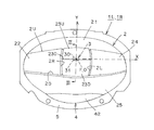
前記レンズ2は、図1、図3に示すように、入射面20と、出射面21、22、23U、23D、24、25(以下、「出射面21〜25」と記載する場合がある)と、から構成されている。前記レンズ2は、前記取付部材を介して前記ヒートシンク部材に、前記半導体型光源3と対向するように、取り付けられている。この例において、前記レンズ2の中心(図示せず)は、前記発光チップ30の前記発光面31の中心O(前記X軸、前記基準光軸Z)に対して、下に位置する。なお、前記レンズ2の中心と前記発光チップ30の前記発光面31の中心Oとを一致もしくはほぼ一致させても良いし、前記レンズ2の中心を前記発光チップ30の前記発光面31の中心Oに対して、上に位置させても良い。
(Description of lens 2)
As shown in FIGS. 1 and 3, the
(入射面20の説明)
前記入射面20は、1個の面から構成されている。前記入射面20は、前記半導体型光源3と対向する面であって、この例では2次曲面または複合2次曲面または自由曲面により連続的に形成されている。前記入射面20は、前記半導体型光源3からの光(直射光)を前記レンズ2中に入射させるものである。
(Description of the incident surface 20)
The
(出射面21〜25の説明)
前記出射面21〜25は、前記半導体型光源3と対向する面と反対側の面であって、この例では自由曲面または複合2次曲面または2次曲面からそれぞれ独立して形成されている。前記出射面21〜25は、前記入射面20から前記レンズ2中に入射した前記半導体型光源3からの光を、外部(前記車両の前方)に、所定の配光パターンP1、P2、P3、P4、P5、LP(図6、図7を参照)として出射(照射)させるものである。
(Description of exit surfaces 21 to 25)
The emission surfaces 21 to 25 are surfaces opposite to the surfaces facing the
前記出射面21〜25は、2本の水平分割段差面(横方向の分割線)2U、2Dにより、上段の前記出射面21と中段の前記出射面22、23U、23D、24と下段の前記出射面25とに分割されている。中段の前記出射面22、23U、23D、24は、2本の垂直分割段差面(縦方向の分割線)2L、2Rにより、左側(走行車線側)の前記出射面24と中央の前記出射面23U、23Dと右側(対向車線側)の前記出射面22とに分割されている。前記出射面21〜25は、前記基準光軸Zを含む部分の中央の中段の前記出射面23U、23Dと、前記基準光軸Zを含まない部分の上段の前記出射面21、左右両側の中段の前記出射面22、24、下段の前記出射面25と、に分割されている。
The emission surfaces 21 to 25 are divided into two horizontal division step surfaces (lateral dividing lines) 2U and 2D, and the
上段の前記出射面21は、中段の前記出射面22、23U、23D、24より、後側に凹んでいる。中段の前記出射面22、23U、23D、24は、下段の前記出射面25より、後側に凹んでいる。中央の中段の前記出射面23U、23Dは、左右両側の中段の前記出射面22、24より、後側に凹んでいる。
The
上段の前記出射面21は、スクリーンの上下の垂直線VU−VDに対して左右対称もしくはほぼ左右対称の拡散配光パターンとしての第1配光パターンP1(図6(A)を参照)を出射する。
The
右側の中段の前記出射面22は、右側の下水平カットオフラインCL1を有する拡散配光パターンとしての第2配光パターンP2(図6(B)を参照)を照射する。
The
中央の中段の前記出射面23U、23Dは、右側の下水平カットオフラインCL1、中央の斜めカットオフラインCL2、左側の上水平カットオフラインCL3を有する集光配光パターンとしての第3配光パターンP3(図6(C)を参照)を照射する。
The
左側の中段の前記出射面24は、左側の上水平カットオフラインCL3を有する拡散配光パターンとしての第4配光パターンP4(図6(D)を参照)を照射する。
The
下段の前記出射面25は、スクリーンの上下の垂直線VU−VDに対して左右対称もしくはほぼ左右対称の拡散配光パターンとしての第5配光パターンP5(図6(E)を参照)を出射する。
The
前記第1配光パターンP1、前記第2配光パターンP2、前記第3配光パターンP3、前記第4配光パターンP4、前記第5配光パターンP5が合成(重畳)されることにより、ロービーム配光パターンLP(図7(A)、(B)を参照)が得られる。 By combining (superimposing) the first light distribution pattern P1, the second light distribution pattern P2, the third light distribution pattern P3, the fourth light distribution pattern P4, and the fifth light distribution pattern P5, a low beam A light distribution pattern LP (see FIGS. 7A and 7B) is obtained.
(基準光軸Zを含む部分の出射面23U、23Dの説明)
前記基準光軸Zを含む部分の前記出射面(中央の中段の前記出射面)23U、23Dは、前記基準光軸Zもしくはその近傍を通る段差面230により、上下に2分割されている。下側の前記出射面23Dは、上側の前記出射面23Uより、光の出射方向側に位置する。すなわち、上側の前記出射面23Uは、下側の前記出射面23Dより、後側に凹んでいる。
(Description of the exit surfaces 23U and 23D of the portion including the reference optical axis Z)
The exit surfaces (the center exit surfaces) 23U and 23D including the reference optical axis Z are vertically divided into two by a
上側の前記出射面23Uのうち前記段差面230側の部分から照射される出射光L3U(図3参照)により形成される発光面像I3U(図4参照)と、下側の前記出射面23Dのうち前記段差面230側の部分から照射される出射光L1D(図3参照)により形成される発光面像I1D(図5参照)とは、相互に重なり合うように、それぞれ配光制御されている。
A light emitting surface image I3U (see FIG. 4) formed by the emitted light L3U (see FIG. 3) emitted from the stepped
上側の前記出射面23Uのうち前記段差面230から離れた部分から照射される出射光L2U、L1U(図3参照)により形成される発光面像I2U、I1U(図4参照)、および、下側の前記出射面23Dのうち前記段差面230から離れた部分から照射される出射光L2D、L3D(図3参照)により形成される発光面像I2D、I3D(図5参照)は、前記段差面230から離れるにつれて下側に位置するように、それぞれ配光制御されている。
Light emitting surface images I2U and I1U (see FIG. 4) formed by the emitted light L2U and L1U (see FIG. 3) irradiated from a portion away from the
(発光面像の発光制御の説明)
以下、前記発光面像I1U、I2U、I3U、I1D、I2D、I3Dの配光制御について図4、図5を参照して説明する。
(Description of light emission control of light emitting surface image)
The light distribution control of the light emitting surface images I1U, I2U, I3U, I1D, I2D, and I3D will be described below with reference to FIGS.
前記発光面像I3Uは、上縁が前記上水平カットオフラインCL3もしくはその近傍に位置し、かつ、右上角が前記上水平カットオフラインCL3と前記斜めカットオフラインCL2との交点もしくはその近傍に位置するように、配光制御されている。前記発光面像I2Uは、右上角が前記斜めカットオフラインCL2もしくはその近傍に位置するように、配光制御されている。前記発光面像I1Uは、上縁が前記下水平カットオフラインCL1の延長線もしくはその近傍に位置し、かつ、右上角が前記下水平カットオフラインCL1と前記斜めカットオフラインCL2との交点もしくはその近傍に位置するように、配光制御されている。 The light emitting surface image I3U has an upper edge located at or near the upper horizontal cutoff line CL3, and an upper right corner located at the intersection or the vicinity of the upper horizontal cutoff line CL3 and the oblique cutoff line CL2. The light distribution is controlled. The light emission surface image I2U is light-distributed so that the upper right corner is positioned at or near the oblique cutoff line CL2. The light emitting surface image I1U has an upper edge located at an extension line of the lower horizontal cutoff line CL1 or in the vicinity thereof, and an upper right corner at an intersection or the vicinity of the lower horizontal cutoff line CL1 and the oblique cutoff line CL2. The light distribution is controlled so as to be positioned.
前記レンズ2の肉厚は、上側の前記出射面23Uの基準光軸Zを含む部分の肉厚が厚く、上側の前記出射面23Uの基準光軸Zから離れた部分の肉厚が薄い。このために、前記レンズ2の分光現象(前記レンズ2の色収差現象)により、上側の前記出射面23Uから出射される前記出射光L1U、L2U、L3Uは、上側にやや赤色の光と下側にやや青色の光とに分光される。この結果、前記発光面像I3U、I2U、I1Uの上縁には、やや赤色の分光Rが存在する。なお、前記発光面像I2U、I1Uの上縁の左側の一部は、前記発光面像I3U、I2U中にそれぞれ重なるので、前記やや赤色の分光Rが消えている。
Regarding the thickness of the
前記発光面像I1Dは、上縁が前記上水平カットオフラインCL3もしくはその近傍に位置し、かつ、右上角が前記上水平カットオフラインCL3と前記斜めカットオフラインCL2との交点もしくはその近傍に位置するように、配光制御されている。前記発光面像I2Dは、右上角が前記斜めカットオフラインCL2もしくはその近傍に位置するように、配光制御されている。前記発光面像I3Dは、上縁が前記下水平カットオフラインCL1の延長線もしくはその近傍に位置し、かつ、右上角が前記下水平カットオフラインCL1と前記斜めカットオフラインCL2との交点もしくはその近傍に位置するように、配光制御されている。 The light emitting surface image I1D has an upper edge located at the upper horizontal cut-off line CL3 or the vicinity thereof, and an upper right corner located at an intersection or the vicinity of the upper horizontal cut-off line CL3 and the oblique cut-off line CL2. The light distribution is controlled. The light emitting surface image I2D is light-distributed so that the upper right corner is positioned at or near the oblique cutoff line CL2. The light emitting surface image I3D has an upper edge located at an extension line of the lower horizontal cutoff line CL1 or in the vicinity thereof, and an upper right corner at an intersection or the vicinity of the lower horizontal cutoff line CL1 and the oblique cutoff line CL2. The light distribution is controlled so as to be positioned.
前記レンズ2の肉厚は、下側の前記出射面23Dの基準光軸Zを含む部分の肉厚が厚く、下側の前記出射面23Dの基準光軸Zから離れた部分の肉厚が薄い。このために、前記レンズ2の分光現象(前記レンズ2の色収差現象)により、下側の前記出射面23Dから出射される前記出射光L1D、L2D、L3Dは、上側にやや青色の光と下側にやや赤色の光とに分光される。この結果、前記発光面像I1D、I2D、I3Dの上縁には、やや青色の分光Bが存在する。なお、前記発光面像I2D、I3Dの上縁の左側の一部は、前記発光面像I1D、I2D中にそれぞれ重なるので、前記やや青色の分光Bが消えている。
Regarding the thickness of the
(出射光、発光面像、配光パターンの説明)
図3に示す前記出射光L1U、L2U、L3U、L1D、L2D、L3Dは、この例では、前記基準光軸Zを含む部分の前記出射面(中央の中段の前記出射面)23U、23Dの縦断面(図1におけるIII−III線断面)の任意の点から外部に出射(照射)されている光である。図4、図5に示す前記発光面像I1U、I2U、I3U、I1D、I2D、I3Dは、この例では、図3に示す出射光L1U、L2U、L3U、L1D、L2D、L3Dによりそれぞれ形成される像である。
(Explanation of outgoing light, light emitting surface image, light distribution pattern)
In this example, the emitted lights L1U, L2U, L3U, L1D, L2D, and L3D shown in FIG. 3 are longitudinal sections of the emission surfaces (the emission surfaces in the middle middle stage) 23U and 23D of the portion including the reference optical axis Z. It is the light emitted (irradiated) to the outside from an arbitrary point on the surface (III-III line cross section in FIG. 1). In this example, the light emitting surface images I1U, I2U, I3U, I1D, I2D, and I3D shown in FIGS. It is a statue.
前記基準光軸Zを含む部分の前記出射面23U、23Dの全面からは、図3に示す前記出射光L1U、L2U、L3U、L1D、L2D、L3Dと同様に、それぞれ配光制御されている出射光(図示せず)が外部に出射されている。前記基準光軸Zを含む部分の前記出射面23U、23Dの全面から出射されている前記出射光により、図4、図5に示す前記発光面像I1U、I2U、I3U、I1D、I2D、I3Dと同様に、発光面像(図示せず)がそれぞれ形成されている。前記発光面像が重ねられて図6(C)に示す前記第3配光パターンP3が形成されている。 From the entire surfaces of the exit surfaces 23U and 23D including the reference optical axis Z, the light distribution is controlled in the same manner as the exit lights L1U, L2U, L3U, L1D, L2D, and L3D shown in FIG. Irradiation light (not shown) is emitted to the outside. By the emitted light emitted from the entire surface of the emission surfaces 23U and 23D including the reference optical axis Z, the light emitting surface images I1U, I2U, I3U, I1D, I2D, and I3D shown in FIGS. Similarly, light emitting surface images (not shown) are formed. The third light distribution pattern P3 shown in FIG. 6C is formed by superimposing the light emitting surface images.
前記第3配光パターンP3以外の配光パターン(前記第1配光パターンP1、前記第2配光パターンP2、前記第4配光パターンP4、前記第5配光パターンP5)も、図示されていないが、同様に、上段の前記出射面21、左右両側の中段の前記出射面22、24、下段の前記出射面25の全面から出射されている出射光により形成されている発光面像が重ねられて形成されているものである。
Light distribution patterns other than the third light distribution pattern P3 (the first light distribution pattern P1, the second light distribution pattern P2, the fourth light distribution pattern P4, and the fifth light distribution pattern P5) are also illustrated. Similarly, the light emitting surface image formed by the light emitted from the entire surface of the
(補助レンズ部4の説明)
前記レンズ2の下辺には、補助レンズ部4が一体に設けられている。前記補助レンズ部4は、入射面(図示せず)と、全反射面(図示せず)と、出射面42と、から構成されている。前記補助レンズ部4は、前記半導体型光源3からの光を前記入射面から入射して、その入射光を前記全反射面で全反射させ、その全反射光を前記出射面42から出射させ、その出射光L6により、図6(F)、図7(A)に示すオーバーヘッドサイン配光パターンP6として照射する。
(Description of auxiliary lens unit 4)
An
前記補助レンズ部4により形成される前記オーバーヘッドサイン配光パターンP6は、前記レンズ2により形成される前記ロービーム配光パターンLPの主配光パターンに対する補助配光パターンである。
The overhead sign light distribution pattern P6 formed by the
(フランジ部5の説明)
前記レンズ2および前記補助レンズ部4の周囲には、フランジ部5が一体に設けられている。前記フランジ部5は、前記取付部材に取り付けるためのものである。前記フランジ部5を介して前記レンズ2および前記補助レンズ部4は、前記取付部材に取り付けられる。
(Description of flange part 5)
A
(実施形態の作用の説明)
この実施形態にかかる車両用灯具1L、1Rは、以上のごとき構成からなり、以下、その作用について説明する。
(Description of the operation of the embodiment)
The
半導体型光源3を点灯する。すると、半導体型光源3の発光面31からの光の大部分は、レンズ2の1個の入射面20からレンズ2中に屈折して入射する。このとき、入射光は、入射面20において配光制御される。その入射光は、レンズ2の6個の出射面21〜25から外部にそれぞれ屈折して出射する。このとき、出射光は、出射面21〜25において配光制御される。その出射光は、5個の配光パターンP1〜P5として車両の前方に照射される。
The
すなわち、上段の出射面21からは、出射光が出射されて図6(A)に示す第1配光パターンP1として車両の前方に照射される。右側の中段の出射面22からは、出射光が出射されて図6(B) に示す下水平カットオフラインCL1を有する第2配光パターンP2として車両の前方に照射される。中央の中段の上側の出射面23Uおよび下側の出射面23Dからは、出射光L1U、L2U、L3U、L1D、L2D、L3D(図3参照)が出射されて図6(C) に示す下水平カットオフラインCL1、斜めカットオフラインCL2、上水平カットオフラインCL3を有する第3配光パターンP3として車両の前方に照射される。左側の中段の出射面24からは、出射光が出射されて図6(D)に示す上水平カットオフラインCL3を有する第4配光パターンP4として車両の前方に照射される。下段の出射面25からは、出射光が出射されて図6(E) に示す第5配光パターンP5として車両の前方に照射される。
That is, emitted light is emitted from the
前記の5個の配光パターンP1〜P5が重畳されることにより、図7(A)、(B)に示す下水平カットオフラインCL1、斜めカットオフラインCL2、上水平カットオフラインCL3を有するロービーム配光パターンLPが形成される。ここで、第1配光パターンP1および第5配光パターンP5の上縁は、下水平カットオフラインCL1、斜めカットオフラインCL2、上水平カットオフラインCL3より若干下側に位置する。 By superimposing the five light distribution patterns P1 to P5, a low beam light distribution having a lower horizontal cut-off line CL1, an oblique cut-off line CL2, and an upper horizontal cut-off line CL3 shown in FIGS. 7A and 7B. A pattern LP is formed. Here, the upper edges of the first light distribution pattern P1 and the fifth light distribution pattern P5 are located slightly below the lower horizontal cutoff line CL1, the oblique cutoff line CL2, and the upper horizontal cutoff line CL3.
一方、半導体型光源3からの光の一部は、補助レンズ部4の入射面から補助レンズ部4中に屈折して入射する。このとき、入射光は、入射面において配光制御される。その入射光は、補助レンズ部4の全反射面で全反射する。このとき、全反射光は、反射面において配光制御される。その全反射光は、補助レンズ部4の出射面42から外部に屈折して出射する。このとき、出射光は、出射面42において配光制御される。その出射光は、図6(F)、図7(A)に示すオーバーヘッドサイン配光パターンP6として車両の前上方に照射される。
On the other hand, part of the light from the
(実施形態の効果の説明)
この実施形態にかかる車両用灯具1L、1Rは、以上のごとき構成および作用からなり、以下、その効果について説明する。
(Explanation of effect of embodiment)
The
この実施形態にかかる車両用灯具1L、1Rは、レンズ2の出射面21〜25のうち、基準光軸Zを含む部分の出射面23U、23Dが、基準光軸Zもしくはその近傍を通る段差面230により、上下に2分割されているものである。このために、上側の出射面23Uから照射される半導体型光源3の発光面像I3U、I2U、I1U(配光パターン)と、下側の出射面23Dから照射される半導体型光源3の発光面像I1D、I2D、I3D(配光パターン)と、の重なり合いを調整することができる。これにより、上側の出射面23Uから照射される発光面像I3U、I2U、I1Uの分光色(やや赤色)と、下側の出射面23Dから照射される発光面像I1D、I2D、I3Dの分光色(やや青色)とを、混ぜ合わせて消し合うことができる。このように、この実施形態にかかる車両用灯具1L、1Rは、レンズ直射型の車両用灯具において、確実な色消し効果が得られる。
The
特に、この実施形態にかかる車両用灯具1L、1Rは、上側の出射面23Uのうち段差面230側の部分から照射される出射光L3Uにより形成される発光面像I3Uと、下側の出射面23Dのうち段差面230側の部分から照射される出射光L1Dにより形成される発光面像I1Dとが、図3〜図5に示すように、相互に重なり合うように、それぞれ配光制御されている。また、上側の出射面23Uのうち段差面230から離れた部分から照射される出射光L2U、L1Uにより形成される発光面像I2U、I1U、および、下側の出射面23Dのうち段差面230から離れた部分から照射される出射光L2D、L3Dにより形成される発光面像I2D、I3Dが、図3〜図5に示すように、段差面230から離れるにつれて下側に位置するように、それぞれ配光制御されている。
In particular, the
このために、この実施形態にかかる車両用灯具1L、1Rは、発光面像I3U、I2U、I1Uの上縁に存在する分光色(やや赤色)と、発光面像I1D、I2D、I3Dの上縁に存在する分光色(やや青色)とが、相互に打ち消し合うものであるから、レンズ直射型の車両用灯具において、さらに確実な色消し効果が得られる。
For this reason, the
ここで、レンズの出射面のうち、基準光軸Zを含む部分の出射面23が上下に2分割されていない1個の出射面23からなるレンズにおける出射光L1、L2、L3、L4、L5、L6(以下、「出射光L1〜L6」と称する場合がある)および発光面像I1、I2、I3、I4、I5、I6(以下、「発光面像I1〜I6」と称する場合がある)について、図8、図9を参照して説明する。
Here, among the exit surfaces of the lens, the exit light L1, L2, L3, L4, L5 in the lens composed of one
かかるレンズにおいて、半導体型光源3からの光は、レンズの入射面20からレンズ中に入射する。その入射光は、レンズの出射面23から外部に出射光L1〜L6(図8参照)として出射される。その出射光L1〜L6により形成される発光面像I1〜I6は、図9に示すように、カットオフラインCL1、CL2、CL3に沿って、上から下に連続して配光制御される。
In such a lens, the light from the semiconductor-
すなわち、出射光L1により形成される発光面像I1は、上縁が上水平カットオフラインCL3もしくはその近傍に位置し、かつ、右上角が上水平カットオフラインCL3と斜めカットオフラインCL2との交点もしくはその近傍に位置するように、配光制御されている。出射光L2、L3、L4により形成されている発光面像I2、I3、I4は、右上角が斜めカットオフラインCL2もしくはその近傍に位置するように、上から下に連続して配光制御されている。出射光L5により形成される発光面像I5は、上縁が下水平カットオフラインCL1の延長線もしくはその近傍に位置し、かつ、右上角が下水平カットオフラインCL1と斜めカットオフラインCL2との交点もしくはその近傍に位置するように、配光制御されている。出射光L6により形成されている発光面像I6は、下水平カットオフラインCL1よりも下側に位置するように、配光制御されている。 That is, the light emitting surface image I1 formed by the emitted light L1 has an upper edge located at or near the upper horizontal cut-off line CL3 and an upper right corner at the intersection of the upper horizontal cut-off line CL3 and the oblique cut-off line CL2. Light distribution is controlled so as to be located in the vicinity. The light-emitting surface images I2, I3, and I4 formed by the emitted lights L2, L3, and L4 are subjected to light distribution control continuously from the top to the bottom so that the upper right corner is located at or near the oblique cutoff line CL2. Yes. The light emitting surface image I5 formed by the emitted light L5 has an upper edge located at or near the extension line of the lower horizontal cutoff line CL1, and an upper right corner at the intersection of the lower horizontal cutoff line CL1 and the oblique cutoff line CL2. Light distribution is controlled so as to be located in the vicinity thereof. Light distribution control is performed so that the light emitting surface image I6 formed by the emitted light L6 is positioned below the lower horizontal cut-off line CL1.
かかるレンズの肉厚は、出射面23の基準光軸Zを含む部分(出射面23の中央部分)の肉厚が厚く、出射面23の基準光軸Zから離れた部分(出射面23の周辺部分)の肉厚が薄い。このために、レンズの分光現象(レンズの色収差現象)により、出射面23の上側の部分から出射される出射光L1、L2の上側にやや赤色の光と下側にやや青色の光とに分光され、一方、出射面23の下側の部分から出射される出射光L6、L5の上側にやや青色の光と下側にやや赤色の光とに分光される。なお、出射面23の基準光軸Zを含む部分から出射される出射光L3、L4は、レンズの分光現象(レンズの色収差現象)の影響を受けない。もしくは、受けてもその影響が小さい。
The thickness of the lens is such that the portion including the reference optical axis Z of the exit surface 23 (the central portion of the exit surface 23) is thick, and the portion of the
この結果、発光面像I1、I2の上縁には、やや赤色の分光Rが存在する。なお、前記発光面像I2の上縁の左側の一部は、発光面像I1U中に重なるので、やや赤色の分光Rが消えている。一方、発光面像I6、I5の上縁には、やや青色の分光Bが存在する。なお、発光面像I6、I5の上縁の左側の一部は、発光面像I5、I4、I3中にそれぞれ重なるので、やや青色の分光Bが消えている。 As a result, a slightly red spectrum R exists at the upper edges of the light emitting surface images I1 and I2. Note that a part of the left side of the upper edge of the light emitting surface image I2 overlaps with the light emitting surface image I1U, and therefore the red spectrum R is slightly lost. On the other hand, a slightly blue spectrum B exists at the upper edges of the light emitting surface images I6 and I5. Note that a part of the left side of the upper edge of the light emitting surface images I6 and I5 overlaps with the light emitting surface images I5, I4 and I3, respectively, so that the blue spectrum B is slightly lost.
このように、かかるレンズにおいては、図9に示すように、上水平カットオフラインCL3にやや赤色の分光Rが、下水平カットオフラインCL1にやや青色の分光Bが、斜めカットオフラインCL2にやや赤色の分光Rとやや青色の分光Bとが、それぞれ現れて目立つ。 Thus, in such a lens, as shown in FIG. 9, a slightly red spectrum R is present in the upper horizontal cutoff line CL3, a slightly blue spectrum B is present in the lower horizontal cutoff line CL1, and a slightly red spectrum B is present in the oblique cutoff line CL2. The spectrum R and the slightly blue spectrum B appear and stand out.
これに対して、この実施形態にかかる車両用灯具1L、1Rは、レンズ2の基準光軸Zを含む部分の出射面23U、23Dを段差面230で上下に2分割するものであるから、上側の出射面23Uから照射される発光面像I3U、I2U、I1Uと、下側の出射面23Dから照射される発光面像I1D、I2D、I3Dと、の重なり合いを調整して、上側の出射面23Uから照射される発光面像I3U、I2U、I1Uの分光色(やや赤色)と、下側の出射面23Dから照射される発光面像I1D、I2D、I3Dの分光色(やや青色)とを、混ぜ合わせて消し合うことができる。
On the other hand, since the
この実施形態にかかる車両用灯具1L、1Rは、1つの材質からなるものであるから、製造が簡単であり、コストが安価である。
Since the
また、この実施形態にかかる車両用灯具1L、1Rは、レンズ2の出射面21〜25のうち、基準光軸Zを含む部分の出射面23U、23Dが、基準光軸Zもしくはその近傍を通る段差面230により、上下に2分割されているものである。このために、基準光軸Zを含む部分の出射面23U、23Dから出射される強い光の出射光L1U、L2U、L3U、L1D、L2D、L3Dの分光色を消すことができるものである。
Further, in the
ここで、特許文献2の車両用灯具は、投影レンズとして屈折率が異なる2つの材質を使用するので、製造上やコスト上で課題がある。特許文献3の車両用灯具は、凸レンズの上方部と下方部とから出射される弱い光の分光色を打ち消し合うものであるから、凸レンズの中央部(凸レンズの基準光軸を含む部分)から出射される強い光の分光色を打ち消し合うことができないという課題がある。
Here, since the vehicular lamp of
これに対して、この実施形態にかかる車両用灯具1L、1Rは、1つの材質からなるものであるから、製造が簡単であり、コストが安価である。また、この実施形態にかかる車両用灯具1L、1Rは、強い光の出射光L1U、L2U、L3U、L1D、L2D、L3Dの分光色を消すことができるものである。
On the other hand, since the
この実施形態にかかる車両用灯具1L、1Rは、基準光軸Zを含む部分の出射面23U、23Dが、斜めカットオフラインCL2を有する第3配光パターンP3を照射するものである。斜めカットオフラインCL2は、ロービーム配光パターンLPのうち、最高光度が存在していて、ドライバーが注視する部分である。このために、ドライバーが注視する斜めカットオフラインCL2部分における分光色を消すことができるので、ドライバーにおいて分光色による煩わしさがなく、視認性が向上する。
In the
この実施形態にかかる車両用灯具1L、1Rは、下側の出射面23Dが上側の出射面23Uより光の出射方向側に位置する。すなわち、上側の出射面23Uが下側の出射面23Dより後側に凹んでいる。このために、段差面230を、上側の出射面23Uから下側の出射面23Dにかけて、上から下に傾斜させることができる。この結果、段差面230から出射する出射光が、上から下に傾斜している段差面230により配光制御されて、レンズ2の基準光軸Zに対して下向きに屈折して出射する。これにより、段差面230からの迷惑光の発生を確実に防ぐことができる。
In the
(実施形態以外の例の説明)
この実施形態においては、車両用前照灯、ロービーム用ヘッドランプについて説明するものである。ところが、この発明においては、車両用前照灯、ロービーム用ヘッドランプ以外の車両用灯具たとえばフォグランプ、ハイビーム用ヘッドランプなどであっても良い。
(Description of example other than embodiment)
In this embodiment, a vehicle headlamp and a low beam headlamp will be described. However, in the present invention, vehicle lamps other than vehicle headlamps and low beam headlamps such as fog lamps and high beam headlamps may be used.
また、この実施形態においては、基準光軸Zを含まない部分の出射面が、上段の出射面21、左右両側の中段の出射面22、24、下段の出射面25と、4個に分割されている。ところが、この発明においては、基準光軸Zを含まない部分の出射面を、1個〜3個、あるいは、5個以上に分割しても良い。
Further, in this embodiment, the part of the exit surface that does not include the reference optical axis Z is divided into four parts, the
さらに、この実施形態においては、レンズ2の下辺に補助レンズ部4を設けて、オーバーヘッドサイン配光パターンP6を形成するものである。ところが、この発明においては、レンズ2の周辺に補助レンズ部を設けて、オーバーヘッドサイン配光パターンP6以外の補助配光パターンを形成するようにしても良い。また、複数個の補助レンズ部を設けて、複数個の補助配光パターンを形成しても良い。さらに、補助レンズ部を設けず、補助配光パターンを形成しなくても良い。
Further, in this embodiment, the
1L、1R 車両用灯具
2 レンズ
20 入射面
21、22、23U、23D、24、25 出射面
23 出射面
230 段差面
3 半導体型光源
30 発光チップ
31 発光面
4 補助レンズ部
42 出射面
5 フランジ部
B やや青色の分光
CL1 下水平カットオフライン
CL2 斜めカットオフライン
CL3 上水平カットオフライン
F 基準焦点
HL−HR スクリーンの左右の水平線
I1U、I2U、I3U、I1D、I2D、I3D 発光面像
I1、I2、I3、I4、I5、I6 発光面像
L1U、L2U、L3U、L1D、L2D、L3D 出射光
L1、L2、L3、L4、L5、L6 出射光
LP ロービーム配光パターン
O 中心
P1 第1配光パターン
P2 第2配光パターン
P3 第3配光パターン
P4 第4配光パターン
P5 第5配光パターン
P6 オーバーヘッドサイン配光パターン
R やや赤色の分光
VU−VD スクリーンの上下の垂直線
X X軸
Y Y軸
Z 基準光軸(Z軸)
1L,
Claims (4)
前記レンズは、入射面と、出射面と、から構成されていて、
前記出射面は、前記レンズの基準光軸を含む部分と、前記基準光軸を含まない部分と、から形成されていて、
前記基準光軸を含む部分の前記出射面は、前記基準光軸もしくはその近傍を通る段差面により、上下に2分割されている、
ことを特徴とする車両用灯具。 A lens and a semiconductor-type light source,
The lens is composed of an entrance surface and an exit surface,
The exit surface is formed from a portion including a reference optical axis of the lens and a portion not including the reference optical axis,
The exit surface of the portion including the reference optical axis is divided into two vertically by a step surface passing through the reference optical axis or the vicinity thereof.
A vehicular lamp characterized by the above.
上側の前記出射面のうち前記段差面から離れた部分から照射される前記半導体型光源の発光面像、および、下側の前記出射面のうち前記段差面から離れた部分から照射される前記半導体型光源の発光面像は、前記段差面から離れるにつれて下側に位置するように、それぞれ配光制御されている、
ことを特徴とする請求項1に記載の車両用灯具。 The light emitting surface image of the semiconductor-type light source irradiated from the stepped surface side portion of the upper emitting surface, and the semiconductor-type light source irradiated from the stepped surface side portion of the lower emitting surface. The light-emitting surface images are light distribution controlled so that they overlap each other.
A light emitting surface image of the semiconductor-type light source irradiated from a portion of the upper exit surface away from the step surface, and the semiconductor irradiated from a portion of the lower exit surface away from the step surface The light emission surface image of the mold light source is light distribution controlled so as to be positioned on the lower side as the distance from the step surface increases.
The vehicular lamp according to claim 1.
ことを特徴とする請求項1または2に記載の車両用灯具。 The exit surface of the portion including the reference optical axis irradiates a light distribution pattern having an oblique cutoff line.
The vehicular lamp according to claim 1 or 2.
ことを特徴とする請求項1〜3のいずれか1項に記載の車両用灯具。 The lower emission surface is positioned closer to the light emission direction than the upper emission surface.
The vehicular lamp according to any one of claims 1 to 3.
Priority Applications (1)
| Application Number | Priority Date | Filing Date | Title |
|---|---|---|---|
| JP2014032111A JP6303587B2 (en) | 2014-02-21 | 2014-02-21 | Vehicle lighting |
Applications Claiming Priority (1)
| Application Number | Priority Date | Filing Date | Title |
|---|---|---|---|
| JP2014032111A JP6303587B2 (en) | 2014-02-21 | 2014-02-21 | Vehicle lighting |
Publications (2)
| Publication Number | Publication Date |
|---|---|
| JP2015158986A true JP2015158986A (en) | 2015-09-03 |
| JP6303587B2 JP6303587B2 (en) | 2018-04-04 |
Family
ID=54182854
Family Applications (1)
| Application Number | Title | Priority Date | Filing Date |
|---|---|---|---|
| JP2014032111A Active JP6303587B2 (en) | 2014-02-21 | 2014-02-21 | Vehicle lighting |
Country Status (1)
| Country | Link |
|---|---|
| JP (1) | JP6303587B2 (en) |
Cited By (5)
| Publication number | Priority date | Publication date | Assignee | Title |
|---|---|---|---|---|
| KR20170079452A (en) * | 2015-12-30 | 2017-07-10 | 에스엘 주식회사 | A lamp for vehicle |
| EP3372890A1 (en) * | 2017-03-09 | 2018-09-12 | Automotive Lighting Reutlingen GmbH | Motor vehicle headlamp light module |
| US10502381B2 (en) | 2017-09-22 | 2019-12-10 | Nichia Corporation | Light-emitting module and vehicle lamp |
| WO2020218616A1 (en) * | 2019-04-25 | 2020-10-29 | 市光工業株式会社 | Vehicle lighting tool |
| JP2020181813A (en) * | 2019-04-25 | 2020-11-05 | 市光工業株式会社 | Vehicular lighting fixture |
Citations (4)
| Publication number | Priority date | Publication date | Assignee | Title |
|---|---|---|---|---|
| JP2006210295A (en) * | 2005-01-31 | 2006-08-10 | Ichikoh Ind Ltd | Vehicular lighting fixture and vehicular headlight device |
| US20080247188A1 (en) * | 2007-04-04 | 2008-10-09 | Magna International Inc. | Complex projector lens for LED headlamp |
| JP2009289537A (en) * | 2008-05-28 | 2009-12-10 | Koito Mfg Co Ltd | Vehicular lighting lamp tool |
| JP2011228196A (en) * | 2010-04-22 | 2011-11-10 | Stanley Electric Co Ltd | Lighting fixture for vehicle |
-
2014
- 2014-02-21 JP JP2014032111A patent/JP6303587B2/en active Active
Patent Citations (4)
| Publication number | Priority date | Publication date | Assignee | Title |
|---|---|---|---|---|
| JP2006210295A (en) * | 2005-01-31 | 2006-08-10 | Ichikoh Ind Ltd | Vehicular lighting fixture and vehicular headlight device |
| US20080247188A1 (en) * | 2007-04-04 | 2008-10-09 | Magna International Inc. | Complex projector lens for LED headlamp |
| JP2009289537A (en) * | 2008-05-28 | 2009-12-10 | Koito Mfg Co Ltd | Vehicular lighting lamp tool |
| JP2011228196A (en) * | 2010-04-22 | 2011-11-10 | Stanley Electric Co Ltd | Lighting fixture for vehicle |
Cited By (11)
| Publication number | Priority date | Publication date | Assignee | Title |
|---|---|---|---|---|
| KR20170079452A (en) * | 2015-12-30 | 2017-07-10 | 에스엘 주식회사 | A lamp for vehicle |
| KR102002028B1 (en) * | 2015-12-30 | 2019-07-22 | 에스엘 주식회사 | A lamp for vehicle |
| EP3372890A1 (en) * | 2017-03-09 | 2018-09-12 | Automotive Lighting Reutlingen GmbH | Motor vehicle headlamp light module |
| CN108571702A (en) * | 2017-03-09 | 2018-09-25 | 汽车照明罗伊特林根有限公司 | Automotive headlight optical module |
| US10731816B2 (en) | 2017-03-09 | 2020-08-04 | Automotive Lighting Reutlingen Gmbh | Motor vehicle headlight module with light distributions spaced from the cutoff line |
| CN108571702B (en) * | 2017-03-09 | 2022-02-11 | 汽车照明罗伊特林根有限公司 | Motor vehicle headlight light module |
| US10502381B2 (en) | 2017-09-22 | 2019-12-10 | Nichia Corporation | Light-emitting module and vehicle lamp |
| WO2020218616A1 (en) * | 2019-04-25 | 2020-10-29 | 市光工業株式会社 | Vehicle lighting tool |
| JP2020181813A (en) * | 2019-04-25 | 2020-11-05 | 市光工業株式会社 | Vehicular lighting fixture |
| CN113710954A (en) * | 2019-04-25 | 2021-11-26 | 市光工业株式会社 | Vehicle lamp |
| JP7302521B2 (en) | 2019-04-25 | 2023-07-04 | 市光工業株式会社 | vehicle lamp |
Also Published As
| Publication number | Publication date |
|---|---|
| JP6303587B2 (en) | 2018-04-04 |
Similar Documents
| Publication | Publication Date | Title |
|---|---|---|
| JP6131571B2 (en) | Vehicle lighting | |
| JP6127472B2 (en) | Vehicle headlamp | |
| JP5919685B2 (en) | Vehicle headlamp | |
| WO2014208655A1 (en) | Vehicle lamp fitting | |
| JP6303587B2 (en) | Vehicle lighting | |
| JP6205713B2 (en) | Vehicle lighting | |
| JP6409259B2 (en) | Vehicle lighting | |
| JP6119279B2 (en) | Vehicle headlamp | |
| JP6064439B2 (en) | Vehicle headlamp | |
| JP6264847B2 (en) | Vehicle lighting | |
| JP6056616B2 (en) | Vehicle lighting | |
| JP6471457B2 (en) | Vehicle lighting | |
| JP2018045838A (en) | Light emitting module and vehicular lighting fixture | |
| JP6056615B2 (en) | Vehicle lighting | |
| JP6136213B2 (en) | Vehicle lighting | |
| JP6019993B2 (en) | Vehicle headlamp | |
| JP6277612B2 (en) | Vehicle lighting | |
| JP6733715B2 (en) | Vehicle lighting | |
| JP6171175B2 (en) | Vehicle lighting | |
| JP6394080B2 (en) | Vehicle lighting | |
| JP2014203590A (en) | Vehicle lamp | |
| JP6402592B2 (en) | Vehicle headlamp | |
| JP5949086B2 (en) | Vehicle headlamp | |
| JP6277613B2 (en) | Vehicle lighting | |
| JP6264848B2 (en) | Vehicle lighting |
Legal Events
| Date | Code | Title | Description |
|---|---|---|---|
| A621 | Written request for application examination |
Free format text: JAPANESE INTERMEDIATE CODE: A621 Effective date: 20170202 |
|
| A977 | Report on retrieval |
Free format text: JAPANESE INTERMEDIATE CODE: A971007 Effective date: 20171016 |
|
| A131 | Notification of reasons for refusal |
Free format text: JAPANESE INTERMEDIATE CODE: A131 Effective date: 20171024 |
|
| A521 | Request for written amendment filed |
Free format text: JAPANESE INTERMEDIATE CODE: A523 Effective date: 20171221 |
|
| TRDD | Decision of grant or rejection written | ||
| A01 | Written decision to grant a patent or to grant a registration (utility model) |
Free format text: JAPANESE INTERMEDIATE CODE: A01 Effective date: 20180206 |
|
| A61 | First payment of annual fees (during grant procedure) |
Free format text: JAPANESE INTERMEDIATE CODE: A61 Effective date: 20180219 |
|
| R150 | Certificate of patent or registration of utility model |
Ref document number: 6303587 Country of ref document: JP Free format text: JAPANESE INTERMEDIATE CODE: R150 |
|
| R250 | Receipt of annual fees |
Free format text: JAPANESE INTERMEDIATE CODE: R250 |
|
| R250 | Receipt of annual fees |
Free format text: JAPANESE INTERMEDIATE CODE: R250 |
|
| R250 | Receipt of annual fees |
Free format text: JAPANESE INTERMEDIATE CODE: R250 |
|
| R250 | Receipt of annual fees |
Free format text: JAPANESE INTERMEDIATE CODE: R250 |