JP2015114258A - Gas analysis method and gas analyzer - Google Patents
Gas analysis method and gas analyzer Download PDFInfo
- Publication number
- JP2015114258A JP2015114258A JP2013257941A JP2013257941A JP2015114258A JP 2015114258 A JP2015114258 A JP 2015114258A JP 2013257941 A JP2013257941 A JP 2013257941A JP 2013257941 A JP2013257941 A JP 2013257941A JP 2015114258 A JP2015114258 A JP 2015114258A
- Authority
- JP
- Japan
- Prior art keywords
- measurement
- measurement signal
- wavelength
- gas
- obtaining
- Prior art date
- Legal status (The legal status is an assumption and is not a legal conclusion. Google has not performed a legal analysis and makes no representation as to the accuracy of the status listed.)
- Granted
Links
- 238000004868 gas analysis Methods 0.000 title claims abstract description 48
- 238000000034 method Methods 0.000 title claims abstract description 47
- 238000005259 measurement Methods 0.000 claims abstract description 305
- 238000004458 analytical method Methods 0.000 claims abstract description 59
- 230000010355 oscillation Effects 0.000 claims abstract description 46
- 230000003287 optical effect Effects 0.000 claims abstract description 33
- 238000010521 absorption reaction Methods 0.000 claims abstract description 32
- 238000010408 sweeping Methods 0.000 claims abstract description 7
- 239000000428 dust Substances 0.000 description 15
- 238000002485 combustion reaction Methods 0.000 description 11
- 230000002238 attenuated effect Effects 0.000 description 10
- 230000005855 radiation Effects 0.000 description 6
- 238000010586 diagram Methods 0.000 description 5
- XLYOFNOQVPJJNP-UHFFFAOYSA-N water Substances O XLYOFNOQVPJJNP-UHFFFAOYSA-N 0.000 description 5
- 239000003245 coal Substances 0.000 description 3
- 230000008020 evaporation Effects 0.000 description 3
- 238000001704 evaporation Methods 0.000 description 3
- 239000013307 optical fiber Substances 0.000 description 3
- 238000010248 power generation Methods 0.000 description 3
- 230000005540 biological transmission Effects 0.000 description 2
- 239000000446 fuel Substances 0.000 description 2
- 238000004566 IR spectroscopy Methods 0.000 description 1
- 238000004847 absorption spectroscopy Methods 0.000 description 1
- 238000000862 absorption spectrum Methods 0.000 description 1
- 239000003570 air Substances 0.000 description 1
- 238000007796 conventional method Methods 0.000 description 1
- 238000010438 heat treatment Methods 0.000 description 1
- 239000008236 heating water Substances 0.000 description 1
- 230000031700 light absorption Effects 0.000 description 1
- 239000000463 material Substances 0.000 description 1
- 238000003303 reheating Methods 0.000 description 1
- 238000001228 spectrum Methods 0.000 description 1
- 230000003068 static effect Effects 0.000 description 1
- 238000002834 transmittance Methods 0.000 description 1
Images
Landscapes
- Investigating Or Analysing Materials By Optical Means (AREA)
Abstract
Description
本開示はガス分析方法及びガス分析装置に関する。 The present disclosure relates to a gas analysis method and a gas analyzer.
赤外吸収分光法及び赤外吸収分光装置は、赤外線領域での光の吸収を調べることにより、分析対象のガスに含まれる成分の濃度等を分析するのに用いられる。
一般的に、赤外吸収分光法では、計測信号用及びリファレンス信号用の2つの受光素子が用意される。光源から出射した光は2つに分配され、一方の光が、分析対象のガスを通過してから計測信号用の受光素子に入射させられ、他方の光が、ガスを透過せずにリファレンス信号用受光素子に入射させられる。ガスの分析には、計測信号とリファレンス信号の差が用いられる。
The infrared absorption spectroscopic method and the infrared absorption spectroscopic device are used for analyzing the concentration of a component contained in a gas to be analyzed by examining light absorption in the infrared region.
In general, in infrared absorption spectroscopy, two light receiving elements for measurement signals and reference signals are prepared. The light emitted from the light source is divided into two, one of the light passes through the gas to be analyzed and then enters the light receiving element for measurement signal, and the other light does not pass through the gas and the reference signal Incident on the light receiving element. The difference between the measurement signal and the reference signal is used for gas analysis.
かかる従来の方法に対し、特許文献1は、赤外線吸光スペクトルのベースライン補正方法を開示しており、該方法により得られる補正されたベースラインを用いれば、リファレンス信号の測定が不要になるものと考えられる。より詳しくは、特許文献1に記載された方法では、電気的スペクトルにおいてピークが検出され、該ピークに対応する領域のデータが消去され、そして、消去された領域の両側の2点を基準にしてデータが補間される。
In contrast to this conventional method,
一方、赤外吸収分光装置には、光源として、波長可変ダイオードレーザを用いるものがある。この種の赤外吸収分光装置として、例えば特許文献2に記載されたレーザ計測装置では、光源から出射するレーザ光の波長及び強度が掃引される。このレーザ計測装置では、計測信号とリファレンス信号の両方が測定されており、レーザ光の強度が三角波状に掃引されていても、計測信号とリファレンス信号の差をとることで、掃引の影響を除去することができる。
On the other hand, some infrared absorption spectrometers use a wavelength tunable diode laser as a light source. As this type of infrared absorption spectroscopic apparatus, for example, in a laser measuring apparatus described in
2つの受光素子を用いる場合、光を分配してからそれぞれの受光素子に至るまでの光学系が厳密には同一ではなく、光学系の相違による誤差が生じてしまう。
また、2つの受光素子を用いる場合、環境光や熱輻射により、2つの受光素子の動作特性に相違が発生し、誤差が生じてしまうこともある。
When two light receiving elements are used, the optical systems from the distribution of light to the respective light receiving elements are not exactly the same, and errors due to differences in the optical systems occur.
Further, when two light receiving elements are used, there may be a difference in operating characteristics between the two light receiving elements due to ambient light or thermal radiation, resulting in an error.
これに対し、特許文献1に記載されるように、補正されたベースラインを用いれば、2つの受光素子を用いることに起因する誤差は解消されるものと考えられる。しかしながら、ピークに対応する領域の両側の点を特定するのは困難であり、これらの点の設定によっては、かえって誤差が大きくなってしまう恐れがある。
On the other hand, as described in
そこで、本発明の少なくとも一実施形態の目的は、1つの受光素子を用いて、誤差が確実に低減されるガス分析方法及びガス分析装置を提供することにある。 Accordingly, an object of at least one embodiment of the present invention is to provide a gas analyzing method and a gas analyzing apparatus in which errors are reliably reduced by using one light receiving element.
本発明の少なくとも一実施形態に係るガス分析装置は、
光路の始端に、中心波長を含む波長範囲で発振波長が可変であり且つ前記中心波長が可変に構成された波長可変ダイオードレーザを配置する工程と、
前記光路の終端に、受光素子を配置する工程と、
前記分析対象ガスの吸収線を含む第1計測波長範囲で前記波長可変ダイオードレーザの発振波長を掃引しながら、前記受光素子により第1計測信号を取得する工程と、
前記分析対象ガスの吸収線を含まない第2計測波長範囲で前記波長可変ダイオードレーザの発振波長を掃引しながら、前記受光素子により第2計測信号を取得する工程と、
前記第2計測信号に基づいて前記第1計測信号におけるベースラインを求める工程と、
前記第1計測信号及び前記ベースラインに基づいて、前記分析対象ガスを分析する工程とを備える。
A gas analyzer according to at least one embodiment of the present invention includes:
A step of disposing a wavelength tunable diode laser having an oscillation wavelength variable in a wavelength range including a center wavelength and having the center wavelength variably configured at a start end of an optical path;
Placing a light receiving element at the end of the optical path;
Acquiring the first measurement signal by the light receiving element while sweeping the oscillation wavelength of the wavelength tunable diode laser in the first measurement wavelength range including the absorption line of the gas to be analyzed;
Acquiring a second measurement signal by the light receiving element while sweeping the oscillation wavelength of the wavelength tunable diode laser in a second measurement wavelength range not including the absorption line of the gas to be analyzed;
Obtaining a baseline in the first measurement signal based on the second measurement signal;
Analyzing the target gas based on the first measurement signal and the baseline.
この構成によれば、第1計測信号及び第2計測信号が、同じ受光素子を用いて取得される。このため、第1計測信号と第2計測信号を取得するための光学系が全く同一になり、光学系の相違に起因する誤差が取り除かれる。
一方、この構成によれば、第2計測波長範囲には分析対象ガスの吸収線が含まれておらず、第2計測信号の形状を、略そのままベースラインとして用いることができる。このため、1つの受光素子を用いても、ベースラインを求める際に生じる誤差が殆ど無い。
これらの結果、この構成によれば、第1計測信号及びベースラインに基づいて、分析対象ガスを高精度に分析することができる。
According to this configuration, the first measurement signal and the second measurement signal are acquired using the same light receiving element. For this reason, the optical system for acquiring the first measurement signal and the second measurement signal is exactly the same, and errors due to the difference in the optical system are eliminated.
On the other hand, according to this configuration, the absorption line of the analysis target gas is not included in the second measurement wavelength range, and the shape of the second measurement signal can be used as the baseline almost as it is. For this reason, even if one light receiving element is used, there is almost no error that occurs when obtaining the baseline.
As a result, according to this configuration, it is possible to analyze the analysis target gas with high accuracy based on the first measurement signal and the baseline.
幾つかの実施形態では、
前記第1計測信号を取得する工程において、前記第1計測波長範囲で前記発振波長の掃引を繰り返しながら、複数の前記第1計測信号を取得し、
ガス分析方法は、前記複数の第1計測信号の各々の最大値に基づいて、前記複数の第1計測信号のうち少なくとも1つの第1計測信号に含まれる外乱に起因する外乱成分を求める工程を更に備え、
前記分析対象ガスを分析する工程において、前記少なくとも1つの第1計測信号、該少なくとも1つの第1計測信号に含まれる前記外乱成分、及び、前記ベースラインに基づいて、前記分析対象ガスを分析する。
In some embodiments,
In the step of acquiring the first measurement signal, a plurality of the first measurement signals are acquired while repeating the oscillation wavelength sweep in the first measurement wavelength range,
The gas analysis method includes a step of obtaining a disturbance component caused by a disturbance included in at least one first measurement signal among the plurality of first measurement signals based on a maximum value of each of the plurality of first measurement signals. In addition,
In the step of analyzing the analysis target gas, the analysis target gas is analyzed based on the at least one first measurement signal, the disturbance component included in the at least one first measurement signal, and the baseline. .
光路上に塵埃等が存在する場合、塵埃等によって光が散乱され、第1計測信号が減衰してしまう。つまり、塵埃等が外乱となって、第1計測信号が減衰してしまう。この点、この構成によれば、外乱による外乱成分が、複数の第1計測信号の各々の最大値に基づいて求められ、外乱成分を考慮して分析対象ガスが分析されているので、外乱の影響が低減され、高精度に分析が行われる。 When dust or the like is present on the optical path, light is scattered by the dust or the like, and the first measurement signal is attenuated. That is, dust etc. become disturbance and the first measurement signal is attenuated. In this respect, according to this configuration, the disturbance component due to the disturbance is obtained based on the maximum value of each of the plurality of first measurement signals, and the analysis target gas is analyzed in consideration of the disturbance component. Impact is reduced and analysis is performed with high accuracy.
幾つかの実施形態では、
前記第1計測信号を取得する工程において、前記第1計測波長範囲での前記発振波長の掃引を繰り返しながら、複数の前記第1計測信号を取得し、
ガス分析方法は、前記複数の第1計測信号の各々の最小値に基づいて、前記複数の第1計測信号のうち少なくとも1つの第1計測信号に含まれる迷光に起因する迷光成分を求める工程を更に備え、
前記分析対象ガスを分析する工程において、前記少なくとも1つの第1計測信号、該少なくとも1つの第1計測信号に含まれる前記迷光成分、及び、前記ベースラインに基づいて、前記分析対象ガスを分析する。
In some embodiments,
In the step of acquiring the first measurement signal, while repeating the oscillation wavelength sweep in the first measurement wavelength range, acquiring a plurality of the first measurement signals,
The gas analysis method includes a step of obtaining a stray light component caused by stray light included in at least one first measurement signal among the plurality of first measurement signals based on a minimum value of each of the plurality of first measurement signals. In addition,
In the step of analyzing the analysis target gas, the analysis target gas is analyzed based on the at least one first measurement signal, the stray light component included in the at least one first measurement signal, and the baseline. .
受光素子に輻射光等の迷光が入射する場合、第1計測信号が増加してしまう。この点、この構成によれば、第1計測信号が最小値であるときに受光素子に入射するのは迷光のみであり、迷光成分が、複数の第1計測信号の各々の最小値に基づいて求められる。そして、迷光成分を考慮して分析対象ガスが分析されているので、迷光の影響が低減され、高精度に分析が行われる。 When stray light such as radiation is incident on the light receiving element, the first measurement signal is increased. In this respect, according to this configuration, only the stray light is incident on the light receiving element when the first measurement signal has the minimum value, and the stray light component is based on the minimum value of each of the plurality of first measurement signals. Desired. Since the analysis target gas is analyzed in consideration of the stray light component, the influence of the stray light is reduced and the analysis is performed with high accuracy.
幾つかの実施形態では、
前記第1計測信号を取得する工程において、前記第1計測波長範囲での前記発振波長の掃引をインターバルを置いて繰り返す。
この構成によれば、インターバルに対応して、第1計測信号の最小値が一定時間現れるようにすることで、迷光成分をより正確に求めることができる。この結果として、ガスの分析がより高精度に行われる。
In some embodiments,
In the step of acquiring the first measurement signal, the oscillation wavelength sweep in the first measurement wavelength range is repeated at intervals.
According to this configuration, the stray light component can be obtained more accurately by causing the minimum value of the first measurement signal to appear for a certain time corresponding to the interval. As a result, gas analysis is performed with higher accuracy.
幾つかの実施形態では、
前記第2計測信号を取得する工程において、前記第2計測波長範囲での前記発振波長の掃引を繰り返しながら、複数の前記第2計測信号を取得し、
ガス分析方法は、前記複数の第2計測信号の各々の最大値に基づいて、前記複数の第2計測信号うち少なくとも1つの第2計測信号に含まれる外乱に起因する外乱成分を求める工程を更に備え、
前記ベースラインを求める工程において、前記少なくとも一つの第2計測信号、及び、該少なくとも一つの第2計測信号に含まれる前記外乱成分に基づいて、前記ベースラインを求める。
In some embodiments,
In the step of obtaining the second measurement signal, while repeating the oscillation wavelength sweep in the second measurement wavelength range, obtaining a plurality of the second measurement signals,
The gas analysis method further includes a step of obtaining a disturbance component caused by a disturbance included in at least one second measurement signal among the plurality of second measurement signals based on the maximum value of each of the plurality of second measurement signals. Prepared,
In the step of obtaining the baseline, the baseline is obtained based on the at least one second measurement signal and the disturbance component included in the at least one second measurement signal.
光路上に塵埃等が存在する場合、塵埃等によって光が散乱され、第2計測信号が減衰してしまう。つまり、塵埃等が外乱となって、第2計測信号が減衰してしまう。この点、この構成によれば、外乱による外乱成分が、複数の第2計測信号の各々の最大値に基づいて求められ、外乱成分を考慮して分析対象ガスが分析されているので、外乱の影響が低減され、高精度に分析が行われる。 When dust or the like is present on the optical path, light is scattered by the dust or the like, and the second measurement signal is attenuated. That is, dust etc. become disturbance and the second measurement signal is attenuated. In this respect, according to this configuration, the disturbance component due to the disturbance is obtained based on the maximum value of each of the plurality of second measurement signals, and the analysis target gas is analyzed in consideration of the disturbance component. Impact is reduced and analysis is performed with high accuracy.
幾つかの実施形態では、
前記第2計測信号を取得する工程において、前記第2計測波長範囲での前記発振波長の掃引を繰り返しながら、複数の前記第2計測信号を取得し、
ガス分析方法は、前記複数の第2計測信号の各々の最小値に基づいて、前記複数の第2計測信号のうち少なくとも1つの第2計測信号に含まれる迷光に起因する迷光成分を求める工程を更に備え、
前記ベースラインを求める工程において、前記少なくとも一つの第2計測信号、及び、該少なくとも一つの第2計測信号に含まれる前記迷光成分に基づいて、前記ベースラインを求める。
In some embodiments,
In the step of obtaining the second measurement signal, while repeating the oscillation wavelength sweep in the second measurement wavelength range, obtaining a plurality of the second measurement signals,
The gas analysis method includes a step of obtaining a stray light component caused by stray light included in at least one second measurement signal among the plurality of second measurement signals based on a minimum value of each of the plurality of second measurement signals. In addition,
In the step of obtaining the baseline, the baseline is obtained based on the at least one second measurement signal and the stray light component included in the at least one second measurement signal.
受光素子に輻射光等の迷光が入射する場合、第2計測信号が増加してしまう。この点、この構成によれば、第1計測信号が最小値であるときに受光素子に入射するのは迷光のみであり、迷光成分が、複数の第2計測信号の各々の最小値に基づいて求められる。そして、迷光成分を考慮して分析対象ガスが分析されているので、迷光の影響が低減され、高精度に分析が行われる。 When stray light such as radiation is incident on the light receiving element, the second measurement signal is increased. In this respect, according to this configuration, only the stray light is incident on the light receiving element when the first measurement signal has the minimum value, and the stray light component is based on the minimum value of each of the plurality of second measurement signals. Desired. Since the analysis target gas is analyzed in consideration of the stray light component, the influence of the stray light is reduced and the analysis is performed with high accuracy.
幾つかの実施形態では、
前記第2計測信号を取得する工程において、前記第2計測波長範囲での前記発振波長の掃引をインターバルを置いて繰り返す。
この構成によれば、インターバルに対応して、第2計測信号の最小値が一定時間現れるようにすることで、迷光成分をより正確に求めることができる。この結果として、ガスの分析がより高精度に行われる。
In some embodiments,
In the step of obtaining the second measurement signal, the oscillation wavelength sweep in the second measurement wavelength range is repeated at intervals.
According to this configuration, the stray light component can be obtained more accurately by causing the minimum value of the second measurement signal to appear for a certain time corresponding to the interval. As a result, gas analysis is performed with higher accuracy.
本発明の少なくとも一実施形態に係るガス分析装置は、
光路の始端に配置され、中心波長を含む波長範囲で発振波長が可変であり且つ前記中心波長が可変に構成された波長可変ダイオードレーザと、
前記光路の終端に配置される受光素子と、
前記受光素子の出力信号に基づいて、分析対象ガスを分析するように構成された計測器とを備え、
前記計測器は、
前記分析対象ガスの吸収線を含む第1計測波長範囲で前記波長可変ダイオードレーザの発振波長が掃引されている間に前記受光素子により第1計測信号を取得し、
前記分析対象ガスの吸収線を含まない第2計測波長範囲で前記波長可変ダイオードレーザの発振波長が掃引されている間に前記受光素子により第2計測信号を取得し、
前記第2計測信号に基づいて前記第1計測信号におけるベースラインを求め、
前記第1計測信号及び前記ベースラインに基づいて、前記分析対象ガスを分析する
ように構成されている。
A gas analyzer according to at least one embodiment of the present invention includes:
A wavelength tunable diode laser disposed at the beginning of the optical path, the oscillation wavelength being variable in a wavelength range including the center wavelength, and the center wavelength being variably configured;
A light receiving element disposed at the end of the optical path;
A measuring instrument configured to analyze an analysis target gas based on an output signal of the light receiving element;
The measuring instrument is
A first measurement signal is acquired by the light receiving element while the oscillation wavelength of the wavelength tunable diode laser is swept in a first measurement wavelength range including an absorption line of the analysis target gas;
A second measurement signal is acquired by the light receiving element while the oscillation wavelength of the wavelength tunable diode laser is swept in a second measurement wavelength range not including the absorption line of the analysis target gas;
Obtaining a baseline in the first measurement signal based on the second measurement signal;
The analysis target gas is analyzed based on the first measurement signal and the baseline.
この構成によれば、第1計測信号及び第2計測信号が、同じ受光素子を用いて取得される。このため、第1計測信号と第2計測信号を取得するための光学系が全く同一になり、光学系の相違に起因する誤差が取り除かれる。
一方、この構成によれば、第2計測波長範囲には分析対象ガスの吸収線が含まれておらず、第2計測信号の形状を、略そのままベースラインとして用いることができる。このため、1つの受光素子を用いても、ベースラインを求める際に生じる誤差が殆ど無い。
これらの結果、この構成によれば、第1計測信号及びベースラインに基づいて、分析対象ガスを高精度に分析することができる。
According to this configuration, the first measurement signal and the second measurement signal are acquired using the same light receiving element. For this reason, the optical system for acquiring the first measurement signal and the second measurement signal is exactly the same, and errors due to the difference in the optical system are eliminated.
On the other hand, according to this configuration, the absorption line of the analysis target gas is not included in the second measurement wavelength range, and the shape of the second measurement signal can be used as the baseline almost as it is. For this reason, even if one light receiving element is used, there is almost no error that occurs when obtaining the baseline.
As a result, according to this configuration, it is possible to analyze the analysis target gas with high accuracy based on the first measurement signal and the baseline.
幾つかの実施形態では、
前記計測器は、
前記第1計測波長範囲での前記発振波長の掃引が繰り返されている間における複数の前記第1計測信号を取得し、
前記複数の第1計測信号の各々の最大値に基づいて、前記複数の第1計測信号のうち少なくとも1つの第1計測信号に含まれる外乱に起因する外乱成分を求め、
前記少なくとも1つの第1計測信号、該少なくとも1つの第1計測信号に含まれる前記外乱成分、及び、前記ベースラインに基づいて、前記分析対象ガスを分析する
ように構成されている。
In some embodiments,
The measuring instrument is
Obtaining a plurality of the first measurement signals while the sweep of the oscillation wavelength in the first measurement wavelength range is repeated;
Based on the maximum value of each of the plurality of first measurement signals, a disturbance component caused by a disturbance included in at least one first measurement signal among the plurality of first measurement signals is obtained,
The analysis target gas is configured to be analyzed based on the at least one first measurement signal, the disturbance component included in the at least one first measurement signal, and the baseline.
光路上に塵埃等が存在する場合、塵埃等によって光が散乱され、第1計測信号が減衰してしまう。つまり、塵埃等が外乱となって、第1計測信号が減衰してしまう。この点、この構成によれば、外乱による外乱成分が、複数の第1計測信号の各々の最大値に基づいて求められ、外乱成分を考慮して分析対象ガスが分析されているので、外乱の影響が低減され、高精度に分析が行われる。 When dust or the like is present on the optical path, light is scattered by the dust or the like, and the first measurement signal is attenuated. That is, dust etc. become disturbance and the first measurement signal is attenuated. In this respect, according to this configuration, the disturbance component due to the disturbance is obtained based on the maximum value of each of the plurality of first measurement signals, and the analysis target gas is analyzed in consideration of the disturbance component. Impact is reduced and analysis is performed with high accuracy.
幾つかの実施形態では、
前記計測器は、
前記第1計測波長範囲での前記発振波長の掃引が繰り返されている間における複数の前記第1計測信号を取得し、
前記複数の第1計測信号の各々の最小値に基づいて、前記複数の第1計測信号のうち少なくとも1つの第1計測信号に含まれる迷光に起因する迷光成分を求め、
前記少なくとも1つの第1計測信号、該少なくとも1つの第1計測信号に含まれる前記迷光成分、及び、前記ベースラインに基づいて、前記分析対象ガスを分析する
ように構成されている。
In some embodiments,
The measuring instrument is
Obtaining a plurality of the first measurement signals while the sweep of the oscillation wavelength in the first measurement wavelength range is repeated;
Based on the minimum value of each of the plurality of first measurement signals, a stray light component caused by stray light included in at least one first measurement signal among the plurality of first measurement signals is obtained.
The analysis target gas is analyzed based on the at least one first measurement signal, the stray light component included in the at least one first measurement signal, and the baseline.
受光素子に輻射光等の迷光が入射する場合、第1計測信号が増加してしまう。この点、この構成によれば、第1計測信号が最小値であるときに受光素子に入射するのは迷光のみであり、迷光成分が、複数の第1計測信号の各々の最小値に基づいて求められる。そして、迷光成分を考慮して分析対象ガスが分析されているので、迷光の影響が低減され、高精度に分析が行われる。 When stray light such as radiation is incident on the light receiving element, the first measurement signal is increased. In this respect, according to this configuration, only the stray light is incident on the light receiving element when the first measurement signal has the minimum value, and the stray light component is based on the minimum value of each of the plurality of first measurement signals. Desired. Since the analysis target gas is analyzed in consideration of the stray light component, the influence of the stray light is reduced and the analysis is performed with high accuracy.
幾つかの実施形態では、
前記計測器は、前記第1計測波長範囲での前記発振波長の掃引がインターバルを置いて繰り返されている間における複数の前記第1計測信号を取得するように構成されている。
この構成によれば、インターバルに対応して、第1計測信号の最小値が一定時間現れるようにすることで、迷光成分をより正確に求めることができる。この結果として、ガスの分析がより高精度に行われる。
In some embodiments,
The measuring instrument is configured to acquire a plurality of the first measurement signals while the oscillation wavelength sweep in the first measurement wavelength range is repeated at intervals.
According to this configuration, the stray light component can be obtained more accurately by causing the minimum value of the first measurement signal to appear for a certain time corresponding to the interval. As a result, gas analysis is performed with higher accuracy.
幾つかの実施形態では、
前記計測器は、
前記第2計測波長範囲での前記発振波長の掃引が繰り返されている間における複数の前記第2計測信号を取得し、
前記複数の第2計測信号の各々の最大値に基づいて、前記複数の第2計測信号うち少なくとも1つの第2計測信号に含まれる外乱に起因する外乱成分を求め、
前記少なくとも一つの第2計測信号、及び、該少なくとも一つの第2計測信号に含まれる前記外乱成分に基づいて、前記ベースラインを求める
ように構成されている。
In some embodiments,
The measuring instrument is
Obtaining a plurality of the second measurement signals while the sweep of the oscillation wavelength in the second measurement wavelength range is repeated;
Based on the maximum value of each of the plurality of second measurement signals, a disturbance component caused by a disturbance included in at least one second measurement signal among the plurality of second measurement signals is obtained.
The base line is obtained based on the at least one second measurement signal and the disturbance component included in the at least one second measurement signal.
光路上に塵埃等が存在する場合、塵埃等によって光が散乱され、第2計測信号が減衰してしまう。つまり、塵埃等が外乱となって、第2計測信号が減衰してしまう。この点、この構成によれば、外乱による外乱成分が、複数の第2計測信号の各々の最大値に基づいて求められ、外乱成分を考慮して分析対象ガスが分析されているので、外乱の影響が低減され、高精度に分析が行われる。 When dust or the like is present on the optical path, light is scattered by the dust or the like, and the second measurement signal is attenuated. That is, dust etc. become disturbance and the second measurement signal is attenuated. In this respect, according to this configuration, the disturbance component due to the disturbance is obtained based on the maximum value of each of the plurality of second measurement signals, and the analysis target gas is analyzed in consideration of the disturbance component. Impact is reduced and analysis is performed with high accuracy.
幾つかの実施形態では、
前記計測器は、
前記第2計測波長範囲での前記発振波長の掃引が繰り返されている間における複数の前記第2計測信号を取得し、
前記複数の第2計測信号の各々の最小値に基づいて、前記複数の第2計測信号のうち少なくとも1つの第2計測信号に含まれる迷光に起因する迷光成分を求め、
前記少なくとも一つの第2計測信号、及び、該少なくとも一つの第2計測信号に含まれる前記迷光成分に基づいて、前記ベースラインを求める
ように構成されている。
In some embodiments,
The measuring instrument is
Obtaining a plurality of the second measurement signals while the sweep of the oscillation wavelength in the second measurement wavelength range is repeated;
Based on the minimum value of each of the plurality of second measurement signals, a stray light component caused by stray light included in at least one second measurement signal among the plurality of second measurement signals is obtained.
The baseline is determined based on the at least one second measurement signal and the stray light component included in the at least one second measurement signal.
受光素子に輻射光等の迷光が入射する場合、第2計測信号が増加してしまう。この点、この構成によれば、第2計測信号が最小値であるときに受光素子に入射するのは迷光のみであり、迷光成分が、複数の第2計測信号の各々の最小値に基づいて求められる。そして、迷光成分を考慮して分析対象ガスが分析されているので、迷光の影響が低減され、高精度に分析が行われる。 When stray light such as radiation is incident on the light receiving element, the second measurement signal is increased. In this respect, according to this configuration, only the stray light is incident on the light receiving element when the second measurement signal has the minimum value, and the stray light component is based on the minimum value of each of the plurality of second measurement signals. Desired. Since the analysis target gas is analyzed in consideration of the stray light component, the influence of the stray light is reduced and the analysis is performed with high accuracy.
幾つかの実施形態では、
前記計測器は、前記第2計測波長範囲での前記発振波長の掃引がインターバルを置いて繰り返されている間における複数の前記第2計測信号を取得するように構成されている。
この構成によれば、インターバルに対応して、第2計測信号の最小値が一定時間現れるようにすることで、迷光成分をより正確に求めることができる。この結果として、ガスの分析がより高精度に行われる。
In some embodiments,
The measuring instrument is configured to acquire a plurality of the second measurement signals while the oscillation wavelength sweep in the second measurement wavelength range is repeated at intervals.
According to this configuration, the stray light component can be obtained more accurately by causing the minimum value of the second measurement signal to appear for a certain time corresponding to the interval. As a result, gas analysis is performed with higher accuracy.
本発明の少なくとも一実施形態によれば、1つの受光素子を用いて、誤差が確実に低減されるガス分析方法及びガス分析装置が提供される。 According to at least one embodiment of the present invention, there is provided a gas analysis method and a gas analysis apparatus in which errors are reliably reduced by using one light receiving element.
以下、添付図面を参照して、本発明の実施形態について説明する。ただし、この実施形態に記載されている又は図面に示されている構成部品の寸法、材質、形状及びその相対的配置等は、本発明の範囲をこれに限定する趣旨ではなく、単なる説明例にすぎない。 Embodiments of the present invention will be described below with reference to the accompanying drawings. However, the dimensions, materials, shapes, and relative arrangements of the components described in this embodiment or shown in the drawings are not intended to limit the scope of the present invention, but are merely illustrative examples. Only.
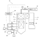
図1は、ボイラ10の概略構成を示す図である。
ボイラ10は、燃焼炉12と、燃焼炉12に連なる煙道14とを有する。
燃焼炉12の火路壁16は水を加熱するための蒸発管を含み、燃焼炉12の上部には、蒸気を過熱するための過熱器18が配置されている。煙道14の下部には、水を予備加熱するための節炭器20が配置されている。また、煙道14の上部には、蒸気を再加熱するための再熱器22が配置されている。
FIG. 1 is a diagram illustrating a schematic configuration of a
The
The
燃焼炉12には、バーナ24が取り付けられ、バーナ24には、送風機26から空気が供給されるとともに石炭粉砕機28から微粉炭が供給可能である。また、燃焼炉12には、空気供給管30が取り付けられ、空気供給管30には送風機26から空気が供給可能である。
A
バーナ24から噴出する微粉炭が燃焼することにより生じた高温の排ガスは、燃焼炉12内を上昇し、煙道14に流入する。燃焼により生じた熱は、火路壁16の蒸発管に伝えられ、これにより水が加熱される。排ガスの熱は、過熱器18での蒸気の過熱、再熱器22での蒸気の再加熱、及び、節炭器20での水の予熱に利用される。低温になった排ガスは、例えばボイラ10の下流に設けられた脱硝装置に流入し、浄化される。
過熱器18で過熱された蒸気(主蒸気)は、例えば、蒸気タービン32に供給され、発電等に利用される。
High-temperature exhaust gas generated by burning pulverized coal ejected from the
The steam (main steam) superheated by the
ボイラ10の制御装置34は、例えば、発電量に基づいてガバナ弁36を制御する一方、主蒸気の圧力に基づいて、ボイラ10における燃焼状態を制御するように構成されている。すなわち、ボイラ10の制御装置34は、燃焼炉12に供給される燃料及び空気の量や、節炭器20を通じて蒸発管に供給される水の量を制御するように構成されている。
For example, the
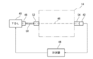
図2は、本発明の一実施形態に係るガス分析装置の概略的な構成を示している。ガス分析装置は、煙道14を流れる排ガスの分析を行うことができる。本実施形態では、ガス分析装置は、図1中に一点鎖線L1で示した位置で、排ガスの分析を行うことができる。すなわち、ガス分析装置は、過熱器18と節炭器20の間で、排ガスの分析を行うことができる。ただし、ガス分析装置は、図1中に一点鎖線L2、L3で示した位置で、排ガスの分析を行ってもよい。つまり、ガス分析装置は、燃焼炉12内で排ガスの分析を行ってもよい。
FIG. 2 shows a schematic configuration of a gas analyzer according to an embodiment of the present invention. The gas analyzer can analyze the exhaust gas flowing through the
ガス分析装置は、波長可変ダイオードレーザ40と、受光素子42と、計測器44とを有する。以下では、波長可変ダイオードレーザ40をTDL(Tunable
Diode LASER)とも称する。
The gas analyzer includes a wavelength
Also called Diode LASER).
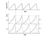
TDL40は、光路46の始端に配置され、レーザ光を出射するように構成されている。図3は、TDL40から出射するレーザ光の強度及び波長と時間との関係を示している。図3に示すように、TDL40は、TDL40に供給する電流を変化させることにより、中心波長λc1を含む波長範囲Δλで発振波長が可変である。本実施形態では、出射光強度が三角波形状(鋸刃形状)に変化させられる。ただし、出射光強度の変調パターンはこれに限定されることはない。
The
また、図3に示すように、TDL40は、TDL40の温度を変化させることにより、波長範囲Δλを超えて、中心波長λc1を例えば中心波長λc2に変化させることができる。なお、温度変化により中心波長を変化させても、供給電流の変調パターンを同一のままにしておけば、波長範囲Δλの大きさ及び出射光強度の変調パターンを同一に維持することができる。
As shown in FIG. 3, the
受光素子42は、光路46の終端に配置され、TDL40が出射したレーザ光を受光する。受光素子42は、例えばフォトダイオードからなる。受光素子42は、入射したレーザ光の強度に対応する信号を出力するように構成されている。
The
光路46の少なくとも一部は、煙道14内、すなわち排ガス流路内を延びている。なお、光路46を規定する光学系の構成は特に限定されることはない。本実施形態では、TDL40は、カプラ48によって光ファイバ50の一端に接続され、光ファイバ50の他端には送光用コリメータ52が取り付けられている。送光用コリメータ52から出射したレーザ光は、煙道14内を横断してから、受光用コリメータ54に入射する。受光素子42は、受光用コリメータ54に取り付けられ、受光用コリメータ54によって収束されたレーザ光が受光素子42に入射する。
At least a part of the
計測器44は、例えばコンピュータによって構成され、受光素子42の出力に基づいて、分析対象のガスを分析するように構成されている。なお、ガスの分析には、例えば、ガスに含まれる成分の濃度分析や、温度の分析が含まれる。
The measuring
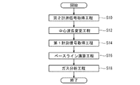
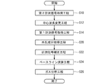
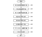
図4は、幾つかの実施形態に係るガス分析方法の手順を概略的に示すフローチャートである。ガス分析方法は、上述したガス分析装置を用いたガス分析に用いることができる。
図4に示したように、ガス分析方法は、第2計測信号取得工程S10と、中心波長変更工程S12と、第1計測信号取得工程S14と、ベースライン演算工程S16と、ガス分析工程S18とを有する。なお、計測器44は、これらの工程S10〜S18を実行可能なように構成されている。
FIG. 4 is a flowchart schematically showing a procedure of a gas analysis method according to some embodiments. The gas analysis method can be used for gas analysis using the above-described gas analyzer.
As shown in FIG. 4, the gas analysis method includes a second measurement signal acquisition step S10, a center wavelength change step S12, a first measurement signal acquisition step S14, a baseline calculation step S16, and a gas analysis step S18. Have The measuring
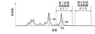
図5は、レーザ光の波長と、ガスによるレーザ光の吸収率との関係を、ガスの吸収線とともに示すグラフである。図5に示すように、ガスは成分に応じて複数の吸収線56を有し、レーザ光は、吸収線56及びその近傍の波長において吸収される。
第2計測信号取得工程S10では、吸収線56を含まない第2計測波長範囲Δλ2でTDL40の発振波長が掃引される。そして、発振波長が掃引されている間、受光素子42の出力(第2計測信号)が取得される。
FIG. 5 is a graph showing the relationship between the wavelength of the laser beam and the absorption rate of the laser beam by the gas, along with the gas absorption line. As shown in FIG. 5, the gas has a plurality of
In the second measurement signal acquisition step S10, the oscillation wavelength of the
ベースライン演算工程S16では、第2計測信号に基づいて、ベースラインが求められる。
中心波長変更工程S12では、分析に用いられる吸収線56が、発振波長が掃引される波長範囲に含まれるように、TDL40の中心波長が変更される。中心波長の変更は、TDL40の温度を調整することにより行われる。なお、TDL40への供給電流の変調パターンは変更されず、中心波長を変更した後の波長範囲(第1計測波長範囲Δλ1)の大きさは第2計測波長範囲Δλ2の大きさと同じであり、出射光強度の変調パターンも変更されない。
In the baseline calculation step S16, a baseline is obtained based on the second measurement signal.
In the center wavelength changing step S12, the center wavelength of the
なお、第2計測波長範囲Δλ2は、分析対象の吸収線56を含んでおらず、吸収が殆どない実質的に透明な範囲であればよく、一部において、第1計測波長範囲Δλ1と重なっていてもよい。一般的に、波長可変ダイオードレーザにあっては、その組成等に応じて発振波長の可変範囲が異なるが、その中から、分析対象のガス種、分析対象の吸収線56、第1計測波長範囲Δλ1及び第2計測波長範囲Δλ2を考慮して、適当な可変範囲を有するものがTDL40として選択される。
Note that the second measurement wavelength range Δλ2 may be a substantially transparent range that does not include the
第1計測信号取得工程S14では、吸収線56を含む第1計測波長範囲Δλ1でTDL40の発振波長が掃引される。そして、発振波長が掃引されている間に、受光素子42の出力(第1計測信号)が取得される。
In the first measurement signal acquisition step S14, the oscillation wavelength of the
ガス分析工程S18では、第1計測信号及びベースラインに基づいて、分析対象ガスが分析される。
分析対象ガスに含まれるガス種の濃度(モル分率)Cや温度は、Lambert−Beer則により、次式(1)及び(2)により求められる。
I/Io=exp(−K(λ)・L) ・・・(1)
K(λ)=P・C・S(T)・φ(λ) ・・・(2)
In the gas analysis step S18, the analysis target gas is analyzed based on the first measurement signal and the baseline.
The concentration (molar fraction) C and temperature of the gas species contained in the analysis target gas are obtained by the following equations (1) and (2) according to the Lambert-Beer rule.
I / Io = exp (−K (λ) · L) (1)
K (λ) = P · C · S (T) · φ (λ) (2)
なお、式(1)及び(2)中、Iは透過光強度、Ioは入射光強度(ベースラインの光強度)、I/Ioは透過率、K(λ)は吸収係数、λは吸収線56の波長、Lは光路長、Pは場の静圧、S(T)は吸収強度温度依存係数、Tはガス種の温度、φ(λ)は吸収線形状関数である。 In equations (1) and (2), I is the transmitted light intensity, Io is the incident light intensity (baseline light intensity), I / Io is the transmittance, K (λ) is the absorption coefficient, and λ is the absorption line. The wavelength is 56, L is the optical path length, P is the static pressure of the field, S (T) is the absorption intensity temperature dependence coefficient, T is the temperature of the gas species, and φ (λ) is the absorption line shape function.
以下、ベースライン演算工程S16について詳細に説明する。
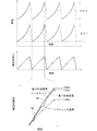
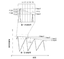
図6は、TDL40の波長、出射光強度、第1計測信号、第2計測信号及びベースラインと、時間の関係を概略的に示している。なお、図6の下段のグラフ中、二点鎖線は、リファレンス信号測定用の受光素子を用意して測定されたリファレンス信号を概略的に示している。図示しないけれども、リファレンス信号測定用の受光素子は、煙道14の手前で光路46から分岐された光路の終端に配置される。
Hereinafter, the baseline calculation step S16 will be described in detail.
FIG. 6 schematically shows the relationship between the wavelength of the
図6の下段のグラフに示すように、第1計測信号の最大値I1maxと、第2計測信号の最大値I2maxとの間には差がある。ベースラインは、最大値I1maxと最大値I2maxとが一致するように、第2計測信号に係数を乗算することにより求められる。
なお、ベースラインは、時間を変数とする近似多項式を用いて近似することができる。そこで、第2計測信号に係数を演算して求められた値を、近似多項式で近似し、得られた近似多項式をベースラインとして用いてもよい。
As shown in the lower graph of FIG. 6, there is a difference between the maximum value I1max of the first measurement signal and the maximum value I2max of the second measurement signal. The baseline is obtained by multiplying the second measurement signal by a coefficient so that the maximum value I1max and the maximum value I2max coincide.
The baseline can be approximated using an approximate polynomial with time as a variable. Therefore, a value obtained by calculating a coefficient for the second measurement signal may be approximated with an approximate polynomial, and the obtained approximate polynomial may be used as a baseline.
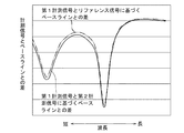
図7は、第2計測信号に基づいて求められたベースラインと第1計測信号との差(差分信号)を概略的に示すグラフである。なお、図7中の二点鎖線は、リファレンス信号に基づいて求められたベースラインと第1計測信号との差を概略的に示している。リファレンス信号に基づくベースラインは、リファレンス信号の最大値Irmaxが第1計測信号の最大値I1maxに一致するように、リファレンス信号に係数を乗算して求められる。
図7に示すように、差分信号の形状は、第2計測信号に基づいて求められたベースラインを用いた場合と、リファレンス用信号を用いた場合とでほぼ同じであるが、一部に違いがある。
FIG. 7 is a graph schematically showing a difference (difference signal) between the baseline and the first measurement signal obtained based on the second measurement signal. In addition, the dashed-two dotted line in FIG. 7 has shown schematically the difference of the base line calculated | required based on the reference signal, and a 1st measurement signal. The baseline based on the reference signal is obtained by multiplying the reference signal by a coefficient so that the maximum value Irmax of the reference signal matches the maximum value I1max of the first measurement signal.
As shown in FIG. 7, the shape of the difference signal is substantially the same between the case where the baseline obtained based on the second measurement signal is used and the case where the reference signal is used, but there are some differences. There is.
上述した構成によれば、第1計測信号及び第2計測信号が、同じ受光素子42を用いて取得される。このため、第1計測信号と第2計測信号を取得するための光学系が全く同一になり、光学系の相違に起因する誤差が取り除かれる。
一方、この構成によれば、第2計測波長範囲Δλ2には分析対象ガスの吸収線56が含まれておらず、第2計測信号の形状を、係数を乗算するとしても、略そのままベースラインとして用いることができる。このため、1つの受光素子42を用いても、ベースラインを求める際に生じる誤差が殆ど無い。
これらの結果、この構成によれば、第1計測信号及びベースラインに基づいて、分析対象ガスを高精度に分析することができる。
According to the configuration described above, the first measurement signal and the second measurement signal are acquired using the same
On the other hand, according to this configuration, the second measurement wavelength range Δλ2 does not include the
As a result, according to this configuration, it is possible to analyze the analysis target gas with high accuracy based on the first measurement signal and the baseline.
図8は、幾つかの実施形態に係るガス分析方法の手順を概略的に示すフローチャートである。ガス分析方法は、上述したガス分析装置を用いたガス分析に用いることができる。
図8に示すガス分析方法は、図4に示すガス分析方法に、第1計測信号に含まれる外乱成分を取得する外乱成分取得工程S20及び計測信号補正工程S22を追加したものである。そして、ベースライン演算工程S24では、計測信号補正工程S22で補正された第1計測信号の最大値I1maxに補正用信号の最大値I2maxが一致するように、補正用信号に係数が乗算される。ガス分析工程S26では、補正された第1計測信号及びベースラインに基づいて分析対象ガスの分析が行われる。
FIG. 8 is a flowchart schematically showing a procedure of a gas analysis method according to some embodiments. The gas analysis method can be used for gas analysis using the above-described gas analyzer.
The gas analysis method shown in FIG. 8 is obtained by adding a disturbance component acquisition step S20 and a measurement signal correction step S22 for acquiring a disturbance component included in the first measurement signal to the gas analysis method shown in FIG. In the baseline calculation step S24, the correction signal is multiplied by a coefficient so that the maximum value I2max of the correction signal matches the maximum value I1max of the first measurement signal corrected in the measurement signal correction step S22. In the gas analysis step S26, the analysis target gas is analyzed based on the corrected first measurement signal and the baseline.
図9は、外乱成分取得工程S20及び計測信号補正工程S22を説明するための図である。
図9に示すように、第1計測信号を繰り返し測定した場合、複数の第1計測信号の最大値I1max1、I1max2、I1max3、・・・が取得される。外乱成分取得工程S20では、複数の第1計測信号の最大値I1max1、I1max2、I1max3、・・・を滑らかに繋ぐ関数f(t)が求められる。
そして、計測信号補正工程S22では、第1計測信号を関数f(t)で割算することにより補正する。
FIG. 9 is a diagram for explaining the disturbance component acquisition step S20 and the measurement signal correction step S22.
9, when the first measurement signal is repeatedly measured, the maximum values I1max1, I1max2, I1max3,... Of the plurality of first measurement signals are acquired. In the disturbance component acquisition step S20, a function f (t) that smoothly connects the maximum values I1max1, I1max2, I1max3,... Of the plurality of first measurement signals is obtained.
And in measurement signal correction process S22, it correct | amends by dividing a 1st measurement signal by the function f (t).
光路46上に塵埃等が存在する場合、塵埃等によって光が散乱され、第1計測信号が減衰してしまう。つまり、塵埃等が外乱となって、第1計測信号が減衰してしまう。この点、この構成によれば、外乱による外乱成分が、複数の第1計測信号の各々の最大値に基づいて求められ、外乱成分を考慮して分析対象ガスが分析されているので、外乱の影響が低減され、高精度に分析が行われる。
When dust or the like is present on the
なお、図9に拡大して概略的に示すように、f(t)は、第1計測信号の最大値と最大値の間における外乱成分も表しており、各時間t1、t2、t3・・・の第1計測信号を、対応するf(t1)、f(t2)、f(t3)・・・で割算するより、第1計測信号を時間ごとに正確に補正することができる。ただし、図9では、説明のために時間のステップが粗いが、実際には連続的に補正することができる。 9, f (t) also represents a disturbance component between the maximum value and the maximum value of the first measurement signal, and each time t1, t2, t3,. The first measurement signal can be accurately corrected every time by dividing the first measurement signal by the corresponding f (t1), f (t2), f (t3). However, in FIG. 9, the time step is rough for the sake of explanation, but in practice it can be corrected continuously.
図10は、幾つかの実施形態に係るガス分析方法の手順を概略的に示すフローチャートである。ガス分析方法は、上述したガス分析装置を用いたガス分析に用いることができる。
図10に示すガス分析方法では、TDL40の出射光強度が、零を最小値として変調される。その上で、図10に示すガス分析方法では、図8に示すガス分析方法に、第1計測信号に含まれる迷光成分を取得する迷光成分取得工程S28が追加される。計測信号補正工程S30では、外乱成分及び迷光成分に基づいて第1計測信号が補正される。ベースライン演算工程S32では、計測信号補正工程S30で補正された第1計測信号の最大値I1maxに補正用信号の最大値I2maxが一致するように、補正用信号に係数が乗算される。ガス分析工程S34では、補正された第1計測信号及びベースラインに基づいて分析対象ガスの分析が行われる。
FIG. 10 is a flowchart schematically showing a procedure of a gas analysis method according to some embodiments. The gas analysis method can be used for gas analysis using the above-described gas analyzer.
In the gas analysis method shown in FIG. 10, the emitted light intensity of the
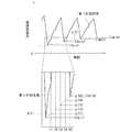
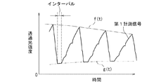
図11は、迷光成分取得工程S28及び計測信号補正工程S30を説明するための図である。
図11に示すように、第1計測信号を繰り返し測定した場合、複数の第1計測信号の最小値I1min1、I1min2、I1min3、・・・が取得される。そして、迷光成分取得工程S28では、複数の第1計測信号の最小値I1min1、I1min2、I1min3、・・・を滑らかに繋ぐ関数g(t)が求められる。
計測信号補正工程S30では、第1計測信号から関数g(t)を引算した値を、関数f(t)で割算することにより、補正された第1計測信号が得られる。
FIG. 11 is a diagram for explaining the stray light component acquisition step S28 and the measurement signal correction step S30.
As shown in FIG. 11, when the first measurement signal is repeatedly measured, the minimum values I1min1, I1min2, I1min3,... Of the plurality of first measurement signals are acquired. In the stray light component acquisition step S28, a function g (t) that smoothly connects the minimum values I1min1, I1min2, I1min3,... Of the plurality of first measurement signals is obtained.
In the measurement signal correction step S30, a corrected first measurement signal is obtained by dividing the value obtained by subtracting the function g (t) from the first measurement signal by the function f (t).
受光素子42に環境光や輻射光等の迷光が入射する場合、第1計測信号が増加してしまう。この点、この構成によれば、TDL40の出射光強度が零を最小値として変調されており、出射光強度が零のときに受光素子42に入射するのは迷光のみであり、迷光成分が、複数の第1計測信号の各々の最小値に基づいて求められる。そして、迷光成分を考慮して分析対象ガスが分析されているので、迷光の影響が低減され、高精度に分析が行われる。
When stray light such as ambient light or radiation light enters the
なお、図11に拡大して概略的に示すように、g(t)は、第1計測信号の最小値と最最小値の間における迷光成分も表しており、各時間t1、t2、t3・・・の第1計測信号から、対応するg(t1)、g(t2)、g(t3)・・・を引算することより、第1計測信号を時間ごとに正確に補正することができる。ただし、図11では、説明のために時間のステップが粗いが、実際には連続的に補正することができる。 As schematically shown in FIG. 11, g (t) also represents a stray light component between the minimum value and the minimum value of the first measurement signal, and each time t1, t2, t3,. By subtracting the corresponding g (t1), g (t2), g (t3)... From the first measurement signal of .., the first measurement signal can be accurately corrected for each time. . However, in FIG. 11, the time step is rough for the sake of explanation, but in practice it can be corrected continuously.
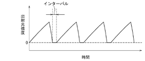
図12及び図13は、幾つかの実施形態に係るガス分析方法を説明するための図である。
図12に示すように、幾つかの実施形態では、TDL40の出射光強度が一定時間零になるインターバルを置いて、TDL40の出射光強度が変調される。このような変調によれば、図13に示すように、第1計測信号にも、インターバルに対応して一定時間最小値が出現する。
このように、第1計測信号の最小値が一定時間現れるようにすることで、迷光成分を表す関数g(t)をより正確に求めることができる。この結果として、ガスの分析がより高精度に行われる。
12 and 13 are diagrams for explaining a gas analysis method according to some embodiments.
As shown in FIG. 12, in some embodiments, the output light intensity of the
As described above, the function g (t) representing the stray light component can be obtained more accurately by causing the minimum value of the first measurement signal to appear for a certain period of time. As a result, gas analysis is performed with higher accuracy.
幾つかの実施形態では、TDL40の出射光強度の変調周波数は、外乱成分や迷光成分の変動周波数よりも高く設定されるが、外乱成分や迷光成分の変動周波数の10倍程度に設定される。例えば、TDL40の出射光強度の変調周波数は、100Hz以上20kHz以下に設定され、好ましくは、100Hz以上1kHz以下に設定される。
この構成によれば、TDL40の出射光強度の変調周波数を低めに抑えることで、第1計測信号や第2計測信号の最大値や最小値に基づいて、外乱成分や迷光成分の変動を正確に求めることができる。また、変調周波数を低めに抑えることで、TDL40、受光素子42及び計測器44として安価なものを用いることができる。
In some embodiments, the modulation frequency of the emitted light intensity of the
According to this configuration, by suppressing the modulation frequency of the emitted light intensity of the
本発明は上述した幾つかの実施形態に限定されることはなく、上述した幾つかの実施形態に変更を加えた形態や、これらの形態を適宜組み合わせた形態も含む。
例えば、上述した幾つかの実施形態では、第1計測信号についてのみ外乱成分の関数f(t)を求めて補正を行ったが、第2計測信号についても同様の方法により外乱成分の関数f(t)を求めて補正を行ってもよい。
上述した幾つかの実施形態では、第1計測信号についてのみ迷光成分の関数g(t)を求めて補正を行ったが、第2計測信号についても同様の方法により迷光成分の関数g(t)を求めて補正を行ってもよい。
The present invention is not limited to the above-described several embodiments, and includes forms obtained by changing some of the above-described embodiments and forms obtained by appropriately combining these forms.
For example, in some of the embodiments described above, the disturbance component function f (t) is obtained and corrected only for the first measurement signal. However, the disturbance component function f ( Correction may be performed by obtaining t).
In some embodiments described above, the function g (t) of the stray light component is obtained and corrected only for the first measurement signal, but the function g (t) of the stray light component is also obtained for the second measurement signal by the same method. May be corrected.
上述した幾つかの実施形態では、迷光成分のための補正を、外乱成分のための補正と併用して行ったが、迷光成分のための補正のみを行ってもよい。
上述した幾つかの実施形態では、迷光成分を演算により補正したが、光学系に迷光除去フィルタを設け、迷光成分を光学的に除去してもよい。
上述した幾つかの実施形態では、第2計測信号を取得した後に第1計測信号を測定したが、第1計測信号を取得した後に、第2計測信号を取得してもよい。
In some embodiments described above, the correction for the stray light component is performed in combination with the correction for the disturbance component, but only the correction for the stray light component may be performed.
In some embodiments described above, the stray light component is corrected by calculation. However, a stray light removal filter may be provided in the optical system to optically remove the stray light component.
In some embodiments described above, the first measurement signal is measured after obtaining the second measurement signal. However, the second measurement signal may be obtained after obtaining the first measurement signal.
上述した幾つかの実施形態において、ガス分析装置による分析結果を制御装置34に入力し、制御装置34が、発電量や主蒸気圧力に加え、ガス分析装置による分析結果に基づいて、ボイラ10への燃料、空気及び水の供給を制御するように構成されていてもよい。
上述した幾つかの実施形態では、ガス分析装置及びガス分析方法は、煙道14を流れる排ガスの分析に適用されていたが、分析対象ガスは、排ガスに限定されることはない。
In some embodiments described above, the analysis result by the gas analyzer is input to the
In some embodiments described above, the gas analyzer and the gas analysis method are applied to the analysis of the exhaust gas flowing through the
40 波長可変ダイオードレーザ(TDL)
42 受光素子
44 計測器
46 光路
48 カプラ
50 光ファイバ
52 送光用コリメータ
54 受光用コリメータ
56 吸収線
40 Tunable diode laser (TDL)
42
Claims (14)
前記光路の終端に、受光素子を配置する工程と、
前記分析対象ガスの吸収線を含む第1計測波長範囲で前記波長可変ダイオードレーザの発振波長を掃引しながら、前記受光素子により第1計測信号を取得する工程と、
前記分析対象ガスの吸収線を含まない第2計測波長範囲で前記波長可変ダイオードレーザの発振波長を掃引しながら、前記受光素子により第2計測信号を取得する工程と、
前記第2計測信号に基づいて前記第1計測信号におけるベースラインを求める工程と、
前記第1計測信号及び前記ベースラインに基づいて、前記分析対象ガスを分析する工程と
を備えることを特徴とするガス分析方法。 A step of disposing a wavelength tunable diode laser having an oscillation wavelength variable in a wavelength range including a center wavelength and having the center wavelength variably configured at a start end of an optical path;
Placing a light receiving element at the end of the optical path;
Acquiring the first measurement signal by the light receiving element while sweeping the oscillation wavelength of the wavelength tunable diode laser in the first measurement wavelength range including the absorption line of the gas to be analyzed;
Acquiring a second measurement signal by the light receiving element while sweeping the oscillation wavelength of the wavelength tunable diode laser in a second measurement wavelength range not including the absorption line of the gas to be analyzed;
Obtaining a baseline in the first measurement signal based on the second measurement signal;
Analyzing the gas to be analyzed based on the first measurement signal and the baseline.
前記複数の第1計測信号の各々の最大値に基づいて、前記複数の第1計測信号のうち少なくとも1つの第1計測信号に含まれる外乱に起因する外乱成分を求める工程を更に備え、
前記分析対象ガスを分析する工程において、前記少なくとも1つの第1計測信号、該少なくとも1つの第1計測信号に含まれる前記外乱成分、及び、前記ベースラインに基づいて、前記分析対象ガスを分析する
ことを特徴とする請求項1に記載のガス分析方法。 In the step of acquiring the first measurement signal, a plurality of the first measurement signals are acquired while repeating the oscillation wavelength sweep in the first measurement wavelength range,
A step of obtaining a disturbance component caused by a disturbance included in at least one first measurement signal among the plurality of first measurement signals based on the maximum value of each of the plurality of first measurement signals;
In the step of analyzing the analysis target gas, the analysis target gas is analyzed based on the at least one first measurement signal, the disturbance component included in the at least one first measurement signal, and the baseline. The gas analysis method according to claim 1.
前記複数の第1計測信号の各々の最小値に基づいて、前記複数の第1計測信号のうち少なくとも1つの第1計測信号に含まれる迷光に起因する迷光成分を求める工程を更に備え、
前記分析対象ガスを分析する工程において、前記少なくとも1つの第1計測信号、該少なくとも1つの第1計測信号に含まれる前記迷光成分、及び、前記ベースラインに基づいて、前記分析対象ガスを分析する
ことを特徴とする請求項1又は2に記載のガス分析方法。 In the step of acquiring the first measurement signal, while repeating the oscillation wavelength sweep in the first measurement wavelength range, acquiring a plurality of the first measurement signals,
A step of obtaining a stray light component caused by stray light included in at least one of the plurality of first measurement signals based on a minimum value of each of the plurality of first measurement signals;
In the step of analyzing the analysis target gas, the analysis target gas is analyzed based on the at least one first measurement signal, the stray light component included in the at least one first measurement signal, and the baseline. The gas analysis method according to claim 1 or 2.
前記複数の第2計測信号の各々の最大値に基づいて、前記複数の第2計測信号うち少なくとも1つの第2計測信号に含まれる外乱に起因する外乱成分を求める工程を更に備え、
前記ベースラインを求める工程において、前記少なくとも一つの第2計測信号、及び、該少なくとも一つの第2計測信号に含まれる前記外乱成分に基づいて、前記ベースラインを求める
ことを特徴とする請求項1乃至4の何れか一項に記載のガス分析方法。 In the step of obtaining the second measurement signal, while repeating the oscillation wavelength sweep in the second measurement wavelength range, obtaining a plurality of the second measurement signals,
A step of obtaining a disturbance component caused by a disturbance included in at least one second measurement signal out of the plurality of second measurement signals based on the maximum value of each of the plurality of second measurement signals;
2. The baseline is obtained based on the disturbance component contained in the at least one second measurement signal and the at least one second measurement signal in the step of obtaining the baseline. The gas analysis method as described in any one of thru | or 4.
前記複数の第2計測信号の各々の最小値に基づいて、前記複数の第2計測信号のうち少なくとも1つの第2計測信号に含まれる迷光に起因する迷光成分を求める工程を更に備え、
前記ベースラインを求める工程において、前記少なくとも一つの第2計測信号、及び、該少なくとも一つの第2計測信号に含まれる前記迷光成分に基づいて、前記ベースラインを求める
ことを特徴とする請求項1乃至5の何れか一項に記載のガス分析方法。 In the step of obtaining the second measurement signal, while repeating the oscillation wavelength sweep in the second measurement wavelength range, obtaining a plurality of the second measurement signals,
A step of obtaining a stray light component caused by stray light included in at least one second measurement signal among the plurality of second measurement signals based on the minimum value of each of the plurality of second measurement signals;
2. The base line is obtained based on the stray light component included in the at least one second measurement signal and the at least one second measurement signal in the step of obtaining the baseline. The gas analysis method as described in any one of thru | or 5.
前記光路の終端に配置される受光素子と、
前記受光素子の出力信号に基づいて、分析対象ガスを分析するように構成された計測器とを備え、
前記計測器は、
前記分析対象ガスの吸収線を含む第1計測波長範囲で前記波長可変ダイオードレーザの発振波長が掃引されている間に前記受光素子により第1計測信号を取得し、
前記分析対象ガスの吸収線を含まない第2計測波長範囲で前記波長可変ダイオードレーザの発振波長が掃引されている間に前記受光素子により第2計測信号を取得し、
前記第2計測信号に基づいて前記第1計測信号におけるベースラインを求め、
前記第1計測信号及び前記ベースラインに基づいて、前記分析対象ガスを分析する
ように構成されていることを特徴とするガス分析装置。 A wavelength tunable diode laser disposed at the beginning of the optical path, the oscillation wavelength being variable in a wavelength range including the center wavelength, and the center wavelength being variably configured;
A light receiving element disposed at the end of the optical path;
A measuring instrument configured to analyze an analysis target gas based on an output signal of the light receiving element;
The measuring instrument is
A first measurement signal is acquired by the light receiving element while the oscillation wavelength of the wavelength tunable diode laser is swept in a first measurement wavelength range including an absorption line of the analysis target gas;
A second measurement signal is acquired by the light receiving element while the oscillation wavelength of the wavelength tunable diode laser is swept in a second measurement wavelength range not including the absorption line of the analysis target gas;
Obtaining a baseline in the first measurement signal based on the second measurement signal;
A gas analyzer configured to analyze the analysis target gas based on the first measurement signal and the baseline.
前記第1計測波長範囲での前記発振波長の掃引が繰り返されている間における複数の前記第1計測信号を取得し、
前記複数の第1計測信号の各々の最大値に基づいて、前記複数の第1計測信号のうち少なくとも1つの第1計測信号に含まれる外乱に起因する外乱成分を求め、
前記少なくとも1つの第1計測信号、該少なくとも1つの第1計測信号に含まれる前記外乱成分、及び、前記ベースラインに基づいて、前記分析対象ガスを分析する
ように構成されていることを特徴とする請求項8に記載のガス分析装置。 The measuring instrument is
Obtaining a plurality of the first measurement signals while the sweep of the oscillation wavelength in the first measurement wavelength range is repeated;
Based on the maximum value of each of the plurality of first measurement signals, a disturbance component caused by a disturbance included in at least one first measurement signal among the plurality of first measurement signals is obtained,
The analysis target gas is analyzed based on the at least one first measurement signal, the disturbance component included in the at least one first measurement signal, and the baseline. The gas analyzer according to claim 8.
前記第1計測波長範囲での前記発振波長の掃引が繰り返されている間における複数の前記第1計測信号を取得し、
前記複数の第1計測信号の各々の最小値に基づいて、前記複数の第1計測信号のうち少なくとも1つの第1計測信号に含まれる迷光に起因する迷光成分を求め、
前記少なくとも1つの第1計測信号、該少なくとも1つの第1計測信号に含まれる前記迷光成分、及び、前記ベースラインに基づいて、前記分析対象ガスを分析する
ように構成されていることを特徴とする請求項8又は9に記載のガス分析装置。 The measuring instrument is
Obtaining a plurality of the first measurement signals while the sweep of the oscillation wavelength in the first measurement wavelength range is repeated;
Based on the minimum value of each of the plurality of first measurement signals, a stray light component caused by stray light included in at least one first measurement signal among the plurality of first measurement signals is obtained.
The analysis target gas is configured to be analyzed based on the at least one first measurement signal, the stray light component included in the at least one first measurement signal, and the baseline. The gas analyzer according to claim 8 or 9.
ことを特徴とする請求項10に記載のガス分析装置。 The measuring instrument is configured to acquire a plurality of the first measurement signals while the oscillation wavelength sweep in the first measurement wavelength range is repeated at intervals. The gas analyzer according to claim 10.
前記第2計測波長範囲での前記発振波長の掃引が繰り返されている間における複数の前記第2計測信号を取得し、
前記複数の第2計測信号の各々の最大値に基づいて、前記複数の第2計測信号うち少なくとも1つの第2計測信号に含まれる外乱に起因する外乱成分を求め、
前記少なくとも一つの第2計測信号、及び、該少なくとも一つの第2計測信号に含まれる前記外乱成分に基づいて、前記ベースラインを求める
ように構成されている
ことを特徴とする請求項8乃至11の何れか一項に記載のガス分析装置。 The measuring instrument is
Obtaining a plurality of the second measurement signals while the sweep of the oscillation wavelength in the second measurement wavelength range is repeated;
Based on the maximum value of each of the plurality of second measurement signals, a disturbance component caused by a disturbance included in at least one second measurement signal among the plurality of second measurement signals is obtained.
12. The base line is obtained based on the at least one second measurement signal and the disturbance component included in the at least one second measurement signal. The gas analyzer according to any one of the above.
前記第2計測波長範囲での前記発振波長の掃引が繰り返されている間における複数の前記第2計測信号を取得し、
前記複数の第2計測信号の各々の最小値に基づいて、前記複数の第2計測信号のうち少なくとも1つの第2計測信号に含まれる迷光に起因する迷光成分を求め、
前記少なくとも一つの第2計測信号、及び、該少なくとも一つの第2計測信号に含まれる前記迷光成分に基づいて、前記ベースラインを求める
ように構成されている
ことを特徴とする請求項8乃至12の何れか一項に記載のガス分析装置。 The measuring instrument is
Obtaining a plurality of the second measurement signals while the sweep of the oscillation wavelength in the second measurement wavelength range is repeated;
Based on the minimum value of each of the plurality of second measurement signals, a stray light component caused by stray light included in at least one second measurement signal among the plurality of second measurement signals is obtained.
13. The baseline is obtained based on the at least one second measurement signal and the stray light component included in the at least one second measurement signal. The gas analyzer according to any one of the above.
ことを特徴とする請求項13に記載のガス分析装置。
The measuring instrument is configured to acquire a plurality of the second measurement signals while the oscillation wavelength sweep in the second measurement wavelength range is repeated at intervals. The gas analyzer according to claim 13.
Priority Applications (1)
| Application Number | Priority Date | Filing Date | Title |
|---|---|---|---|
| JP2013257941A JP6062354B2 (en) | 2013-12-13 | 2013-12-13 | Gas analysis method and gas analyzer |
Applications Claiming Priority (1)
| Application Number | Priority Date | Filing Date | Title |
|---|---|---|---|
| JP2013257941A JP6062354B2 (en) | 2013-12-13 | 2013-12-13 | Gas analysis method and gas analyzer |
Publications (2)
| Publication Number | Publication Date |
|---|---|
| JP2015114258A true JP2015114258A (en) | 2015-06-22 |
| JP6062354B2 JP6062354B2 (en) | 2017-01-18 |
Family
ID=53528176
Family Applications (1)
| Application Number | Title | Priority Date | Filing Date |
|---|---|---|---|
| JP2013257941A Expired - Fee Related JP6062354B2 (en) | 2013-12-13 | 2013-12-13 | Gas analysis method and gas analyzer |
Country Status (1)
| Country | Link |
|---|---|
| JP (1) | JP6062354B2 (en) |
Cited By (1)
| Publication number | Priority date | Publication date | Assignee | Title |
|---|---|---|---|---|
| JP2019015661A (en) * | 2017-07-10 | 2019-01-31 | 株式会社Ihi | Analyzer |
Citations (5)
| Publication number | Priority date | Publication date | Assignee | Title |
|---|---|---|---|---|
| JP2007218783A (en) * | 2006-02-17 | 2007-08-30 | Hitachi Cable Ltd | Optical fiber type gas concentration detection method and apparatus |
| JP2009216385A (en) * | 2006-05-19 | 2009-09-24 | Toyota Motor Corp | Gas analyzer and wavelength sweeping control method of laser in gas analyzer |
| JP2010217100A (en) * | 2009-03-18 | 2010-09-30 | Toyota Motor Corp | Exhaust gas analyzer |
| JP2012237636A (en) * | 2011-05-11 | 2012-12-06 | Shimadzu Corp | Gas analyzer |
| JP2013050403A (en) * | 2011-08-31 | 2013-03-14 | Shimadzu Corp | Gas analyzer |
-
2013
- 2013-12-13 JP JP2013257941A patent/JP6062354B2/en not_active Expired - Fee Related
Patent Citations (5)
| Publication number | Priority date | Publication date | Assignee | Title |
|---|---|---|---|---|
| JP2007218783A (en) * | 2006-02-17 | 2007-08-30 | Hitachi Cable Ltd | Optical fiber type gas concentration detection method and apparatus |
| JP2009216385A (en) * | 2006-05-19 | 2009-09-24 | Toyota Motor Corp | Gas analyzer and wavelength sweeping control method of laser in gas analyzer |
| JP2010217100A (en) * | 2009-03-18 | 2010-09-30 | Toyota Motor Corp | Exhaust gas analyzer |
| JP2012237636A (en) * | 2011-05-11 | 2012-12-06 | Shimadzu Corp | Gas analyzer |
| JP2013050403A (en) * | 2011-08-31 | 2013-03-14 | Shimadzu Corp | Gas analyzer |
Cited By (1)
| Publication number | Priority date | Publication date | Assignee | Title |
|---|---|---|---|---|
| JP2019015661A (en) * | 2017-07-10 | 2019-01-31 | 株式会社Ihi | Analyzer |
Also Published As
| Publication number | Publication date |
|---|---|
| JP6062354B2 (en) | 2017-01-18 |
Similar Documents
| Publication | Publication Date | Title |
|---|---|---|
| CN101956997B (en) | For the optical interrogation sensors of Combustion System | |
| JP6128361B2 (en) | Multi-component laser gas analyzer | |
| US10234378B2 (en) | Method and system for reduction of influence of baseline distortion in absorption spectroscopy measurements | |
| CN100437165C (en) | Method and apparatus for monitoring and controlling a combustion process | |
| JP6057430B2 (en) | Gas analysis apparatus and gas analysis method using laser light | |
| JP6979704B2 (en) | Temperature measuring device and temperature measuring method | |
| JP4775173B2 (en) | Fiber optic temperature sensor | |
| JP6473367B2 (en) | Gas analysis system | |
| CN102022193A (en) | Systems and methods for closed loop emissions control | |
| JP2015040747A5 (en) | ||
| JP5532608B2 (en) | Laser gas analysis method | |
| JP7624743B2 (en) | Gas analysis device and gas analysis method | |
| KR20170128488A (en) | Laser-based IR spectroscopy to measure sulfur trioxide in the exhaust gas of a gas power plant | |
| JP6062355B2 (en) | Gas analysis method and gas analyzer | |
| JP2016090521A (en) | Gas absorbance measuring device | |
| JP2015114260A (en) | Exhaust gas analyzing apparatus | |
| JP6062354B2 (en) | Gas analysis method and gas analyzer | |
| JP2021128141A (en) | Laser type gas analyzer | |
| Buerkle et al. | Optical sensing of turbine inlet temperature in a pressurized gas turbine combustor | |
| JP2023533541A (en) | Laser heterodyne combustion efficiency monitor and related methods | |
| Spearrin et al. | Mid-infrared laser absorption diagnostics for detonation studies | |
| WO2001071320A1 (en) | Method and apparatus for analyzing vaporized metal | |
| Hou et al. | A TDLAS Temperature Sensor Up to MHz for Fast-Varying Transient Flows | |
| JP2011137645A (en) | Optical gas analysis device, gas analysis method and analysis control method | |
| Yu et al. | A tunable diode-laser absorption spectroscopy (TDLAS) thermometry for combustion diagnostics |
Legal Events
| Date | Code | Title | Description |
|---|---|---|---|
| A625 | Written request for application examination (by other person) |
Free format text: JAPANESE INTERMEDIATE CODE: A625 Effective date: 20151028 |
|
| A977 | Report on retrieval |
Free format text: JAPANESE INTERMEDIATE CODE: A971007 Effective date: 20160831 |
|
| A131 | Notification of reasons for refusal |
Free format text: JAPANESE INTERMEDIATE CODE: A131 Effective date: 20160902 |
|
| A521 | Written amendment |
Free format text: JAPANESE INTERMEDIATE CODE: A523 Effective date: 20161031 |
|
| TRDD | Decision of grant or rejection written | ||
| A01 | Written decision to grant a patent or to grant a registration (utility model) |
Free format text: JAPANESE INTERMEDIATE CODE: A01 Effective date: 20161118 |
|
| A61 | First payment of annual fees (during grant procedure) |
Free format text: JAPANESE INTERMEDIATE CODE: A61 Effective date: 20161214 |
|
| R151 | Written notification of patent or utility model registration |
Ref document number: 6062354 Country of ref document: JP Free format text: JAPANESE INTERMEDIATE CODE: R151 |
|
| LAPS | Cancellation because of no payment of annual fees |