JP2015114011A - Heating cooker - Google Patents

Heating cooker Download PDF

Info

Publication number
JP2015114011A
JP2015114011A JP2013255028A JP2013255028A JP2015114011A JP 2015114011 A JP2015114011 A JP 2015114011A JP 2013255028 A JP2013255028 A JP 2013255028A JP 2013255028 A JP2013255028 A JP 2013255028A JP 2015114011 A JP2015114011 A JP 2015114011A
Authority
JP
Japan
Prior art keywords
heating
time
cooking
key
grill
Prior art date
Legal status (The legal status is an assumption and is not a legal conclusion. Google has not performed a legal analysis and makes no representation as to the accuracy of the status listed.)
Granted
Application number
JP2013255028A
Other languages
Japanese (ja)
Other versions
JP6165041B2 (en
Inventor
杉山 直也
Naoya Sugiyama
直也 杉山
金井 孝博
Takahiro Kanai
孝博 金井
吉川 秀樹
Hideki Yoshikawa
秀樹 吉川
Current Assignee (The listed assignees may be inaccurate. Google has not performed a legal analysis and makes no representation or warranty as to the accuracy of the list.)
Mitsubishi Electric Home Appliance Co Ltd
Mitsubishi Electric Corp
Original Assignee
Mitsubishi Electric Home Appliance Co Ltd
Mitsubishi Electric Corp
Priority date (The priority date is an assumption and is not a legal conclusion. Google has not performed a legal analysis and makes no representation as to the accuracy of the date listed.)
Filing date
Publication date
Application filed by Mitsubishi Electric Home Appliance Co Ltd, Mitsubishi Electric Corp filed Critical Mitsubishi Electric Home Appliance Co Ltd
Priority to JP2013255028A priority Critical patent/JP6165041B2/en
Publication of JP2015114011A publication Critical patent/JP2015114011A/en
Application granted granted Critical
Publication of JP6165041B2 publication Critical patent/JP6165041B2/en
Expired - Fee Related legal-status Critical Current
Anticipated expiration legal-status Critical

Links

Images

Landscapes

  • Electric Ovens (AREA)

Abstract

【課題】連続運転モードで複数の加熱手段を運転した際に、使用者の判断により最適な加熱運転を行うことができる加熱調理器を提供することを目的とする。【解決手段】加熱特性の異なる複数の加熱手段と加熱手段の運転を制御する制御手段とを有し、少なくとも加熱手段のうちの特定の加熱手段の運転に続けて特定の加熱手段以外の他の加熱手段を連続して運転する連続運転モードを備えた加熱調理器であって、制御手段は、連続運転モードの時に予め入力された加熱手段の各運転時間となるよう各加熱手段の運転を行い、特定の加熱手段の運転中に他の加熱手段の運転に移行する移行スキップ操作手段を備えたものである。【選択図】図7An object of the present invention is to provide a cooking device capable of performing an optimum heating operation according to a user's judgment when a plurality of heating means are operated in a continuous operation mode. A plurality of heating means having different heating characteristics and a control means for controlling the operation of the heating means are provided, and at least other than the specific heating means following the operation of the specific heating means among the heating means. A cooking device having a continuous operation mode for continuously operating the heating means, wherein the control means operates each heating means so as to have each operation time of the heating means input in advance in the continuous operation mode. A transition skip operation means for shifting to the operation of another heating means during the operation of the specific heating means is provided. [Selection] Figure 7

Description

本発明は、加熱特性の異なる複数の加熱手段を備え、加熱手段を切り替えて連続運転を行う加熱調理器に関するものである。   The present invention relates to a heating cooker that includes a plurality of heating means having different heating characteristics and performs continuous operation by switching the heating means.

従来、マイクロ波加熱やヒーター加熱など加熱特性の異なる複数の加熱手段を備えた加熱調理器で調理物を加熱する際に、複数の加熱手段を切り替えて連続運転する加熱手段の制御が知られている。この加熱手段の制御は、使用者が手動設定をして複数の加熱手段の運転時間をそれぞれ予め設定し連続運転を行っていた(例えば特許文献1を参照)。   Conventionally, when heating a cooked food with a heating cooker having a plurality of heating means having different heating characteristics such as microwave heating and heater heating, it is known to control the heating means that continuously operates by switching the plurality of heating means. Yes. In the control of the heating means, the user manually sets the operation time of the plurality of heating means in advance and performs continuous operation (see, for example, Patent Document 1).

特開昭58−60133号公報JP-A-58-60133

従来の加熱調理器では、使用者が複数の加熱手段の運転時間を手動設定するため、使用者は調理物の種類や分量などから各加熱時間を予測して設定しなければならず、その設定が適切でなかったとしても各加熱時間を運転途中で変更できないため使い勝手が良くなかった。   In a conventional cooking device, the user manually sets the operation time of a plurality of heating means, so the user must predict and set each heating time based on the type and amount of the cooked food. Even if it was not appropriate, each heating time could not be changed during operation, so it was not convenient.

本発明は、上記のような課題を解決するためになされたもので、連続運転モードで複数の加熱手段を運転した際に、使用者の判断により最適な加熱運転を行うことができる加熱調理器を提供することを目的とする。   The present invention has been made in order to solve the above-described problem, and when a plurality of heating means are operated in a continuous operation mode, a cooking device capable of performing an optimum heating operation according to a user's judgment. The purpose is to provide.

本発明に係る加熱調理器は、加熱特性の異なる複数の加熱手段と前記加熱手段の運転を制御する制御手段とを有し、少なくとも前記加熱手段のうちの特定の加熱手段の運転に続けて前記特定の加熱手段以外の他の加熱手段を連続して運転する連続運転モードを備えた加熱調理器であって、前記制御手段は、前記連続運転モードの時に予め入力された前記加熱手段の各運転時間となるよう各加熱手段の運転を行い、前記特定の加熱手段の運転中に前記他の加熱手段の運転に移行する移行スキップ操作手段を備えたものである。   A heating cooker according to the present invention includes a plurality of heating means having different heating characteristics and a control means for controlling the operation of the heating means, and at least following the operation of a specific heating means of the heating means, A cooking device having a continuous operation mode for continuously operating other heating means other than the specific heating means, wherein the control means operates each of the heating means input in advance in the continuous operation mode. Each heating means is operated so as to have a time, and a transition skip operation means for shifting to the operation of the other heating means during the operation of the specific heating means is provided.

本発明に係る加熱調理器によれば、連続運転モードで複数の加熱手段を運転した際に、加熱運転の途中で次の加熱手段に移行する移行スキップ操作が可能となるため、使用者の判断により最適な加熱運転を実行することができる。   According to the heating cooker according to the present invention, when a plurality of heating means are operated in the continuous operation mode, a transition skip operation for shifting to the next heating means is possible in the middle of the heating operation, so that the user's judgment Thus, the optimum heating operation can be executed.

実施の形態1に係る加熱調理器を示す斜視図である。It is a perspective view which shows the heating cooker which concerns on Embodiment 1. FIG. 実施の形態1に係る加熱調理器を前後方向に切断した側面断面図である。It is side surface sectional drawing which cut | disconnected the heating cooker which concerns on Embodiment 1 in the front-back direction. 実施の形態1に係る加熱調理器の操作部及び表示部の説明図である。It is explanatory drawing of the operation part and display part of the heating cooker which concern on Embodiment 1. FIG. 実施の形態1に係る加熱調理器の制御ブロック図である。It is a control block diagram of the heating cooker according to the first embodiment. 実施の形態1に係る加熱調理器でレンジグリル調理における機能切り替えの操作手順と発光部の点灯状況、および表示部の表示内容を示した説明図である。It is explanatory drawing which showed the operation procedure of the function switching in the range grill cooking with the heating cooker which concerns on Embodiment 1, the lighting condition of a light emission part, and the display content of a display part. 実施の形態1に係る加熱調理器でレンジグリル調理における機能切り替えの操作手順と発光部の点灯状況、および表示部の表示内容を示した説明図である。It is explanatory drawing which showed the operation procedure of the function switching in the range grill cooking with the heating cooker which concerns on Embodiment 1, the lighting condition of a light emission part, and the display content of a display part. 実施の形態1に係る加熱調理器でレンジグリル調理における機能切り替えの操作手順と発光部の点灯状況、および表示部の表示内容を示した説明図である。It is explanatory drawing which showed the operation procedure of the function switching in the range grill cooking with the heating cooker which concerns on Embodiment 1, the lighting condition of a light emission part, and the display content of a display part. 実施の形態1に係る加熱調理器におけるレンジグリル調理の「手動」のモードを使用する場合の操作手順と発光部の点灯状況、及び、表示部の表示内容を示した説明図である。It is explanatory drawing which showed the operation procedure, the lighting condition of a light emission part, and the display content of a display part in the case of using the "manual" mode of the range grill cooking in the heating cooker which concerns on Embodiment 1. FIG. 実施の形態1に係る加熱調理器におけるレンジグリル調理の「手動」のモードを使用する場合の操作手順と発光部の点灯状況、及び、表示部の表示内容を示した説明図である。It is explanatory drawing which showed the operation procedure, the lighting condition of a light emission part, and the display content of a display part in the case of using the "manual" mode of the range grill cooking in the heating cooker which concerns on Embodiment 1. FIG. 実施の形態1に係る加熱調理器におけるレンジグリル調理の「手動」のモードを使用する場合の操作手順と発光部の点灯状況、及び、表示部の表示内容を示した説明図である。It is explanatory drawing which showed the operation procedure, the lighting condition of a light emission part, and the display content of a display part in the case of using the "manual" mode of the range grill cooking in the heating cooker which concerns on Embodiment 1. FIG. 実施の形態1に係る加熱調理器におけるレンジグリル調理の「手動」のモードを使用する場合の操作手順と発光部の点灯状況、及び、表示部の表示内容を示した説明図である。It is explanatory drawing which showed the operation procedure, the lighting condition of a light emission part, and the display content of a display part in the case of using the "manual" mode of the range grill cooking in the heating cooker which concerns on Embodiment 1. FIG. 実施の形態1に係る加熱調理器におけるレンジグリル調理の「手動」のモードを使用する場合の操作手順と発光部の点灯状況、及び、表示部の表示内容を示した説明図である。It is explanatory drawing which showed the operation procedure, the lighting condition of a light emission part, and the display content of a display part in the case of using the "manual" mode of the range grill cooking in the heating cooker which concerns on Embodiment 1. FIG. 実施の形態1に係るレンジグリル調理の手動モード時におけるレンジ調理時の報知、移行スキップ制御を示す制御フロー図である。It is a control flow figure showing information at the time of range cooking at the time of manual mode of range grill cooking concerning Embodiment 1, and shift skip control. 実施の形態1に係るレンジグリル調理の手動モード時におけるグリル調理時の報知、終了スキップ制御を示す制御フロー図である。It is a control flowchart which shows the notification at the time of grill cooking in the manual mode of the range grill cooking which concerns on Embodiment 1, and completion | finish skip control. 実施の形態1に係るグリル調理時の加熱室内の温度変化と予測終了時間t2a_endとの関係を示した図である。It is the figure which showed the relationship between the temperature change in the heating chamber at the time of grill cooking which concerns on Embodiment 1, and prediction end time t2a_end. 実施の形態2に係るレンジグリル調理の手動モード時における設定時間変更制御を示す制御フロー図である。FIG. 10 is a control flow diagram showing set time change control in a manual mode of range grill cooking according to Embodiment 2.

以下、本発明に係る加熱調理器について、図面を用いて説明する。
なお、以下で説明する構成や制御内容等は、一例であり、本発明に係る加熱調理器は、そのような構成や制御内容等に限定されない。
また、細かい構造については、適宜図示を簡略化又は省略している。
また、重複又は類似する説明については、適宜簡略化又は省略している。
Hereinafter, the cooking device according to the present invention will be described with reference to the drawings.
In addition, the structure, control content, etc. which are demonstrated below are examples, and the heating cooker which concerns on this invention is not limited to such a structure, control content, etc.
Further, the illustration of the fine structure is simplified or omitted as appropriate.
In addition, overlapping or similar descriptions are appropriately simplified or omitted.

以下、本発明の実施の形態について図面を用いて説明する。
実施の形態1.
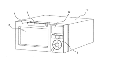
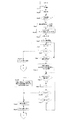
図1は、実施の形態1に係る加熱調理器を示す斜視図である。
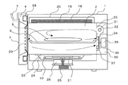
図2は、実施の形態1に係る加熱調理器を前後方向に切断した側面断面図である。
図1に示すように、本実施の形態における加熱調理器は、本体1の内部に調理物5を加熱調理する加熱室(加熱エリア)2を備え、本体1の前側には窓3を有するドア4が設けられている。このドア4は、下部を本体1に軸支されており、上部に設けられたハンドル7により開閉可能に構成されている。
そして、加熱調理器を正面から見てドア4の右側に位置する略長方形状の領域は、使用者が後述する複数のキーを用いて調理に関する所定の入力を行う操作部8が形成されている。また、この操作部8には、操作入力の状態と調理状況を表示する表示部9が設けられている。
Hereinafter, embodiments of the present invention will be described with reference to the drawings.
Embodiment 1 FIG.
1 is a perspective view showing a heating cooker according to Embodiment 1. FIG.
FIG. 2 is a side cross-sectional view of the cooking device according to Embodiment 1 cut in the front-rear direction.
As shown in FIG. 1, the heating cooker according to the present embodiment includes a heating chamber (heating area) 2 for cooking cooking 5 inside the main body 1, and a door having a window 3 on the front side of the main body 1. 4 is provided. The lower portion of the door 4 is pivotally supported by the main body 1 and can be opened and closed by a handle 7 provided at the upper portion.
And the operation part 8 which the user performs the predetermined | prescribed input regarding cooking using the some key mentioned later is formed in the substantially rectangular area | region located in the right side of the door 4 seeing a heating cooker from the front. . In addition, the operation unit 8 is provided with a display unit 9 for displaying an operation input state and cooking status.

次に、加熱室2内部には、調理物5を載置するセラミックによって構成された調理プレート6が着脱自在に設置され、加熱室2側面に設けられたガイドレール(図示せず)に支持されるように構成されている。
加熱室2の上面外側には、発熱体であるニクロム線をマイカで挟んで構成したフラットヒーター18が配置されている。フラットヒーター18は、断熱材19と、これらを覆う板金20によって上部を覆われており、加熱室2内部を加熱するように構成されている。
Next, a cooking plate 6 made of ceramic on which the food 5 is placed is detachably installed inside the heating chamber 2 and is supported by guide rails (not shown) provided on the side of the heating chamber 2. It is comprised so that.
A flat heater 18 configured by sandwiching a nichrome wire as a heating element between mica is disposed outside the upper surface of the heating chamber 2. The flat heater 18 is covered with a heat insulating material 19 and a sheet metal 20 that covers them, and is configured to heat the inside of the heating chamber 2.

次に、加熱室2の下部には、本体1内に設置されたマグネトロン38の発生する周波数約2450MHzのマイクロ波を、加熱室2に伝播するアンテナ21が備えられている。
このアンテナ21は、加熱室2とセラミックプレート23で隔てられた下部加熱室24内に、回転可能に軸支され、アンテナモーター25によって回転しながら、導波管26を介して伝播されるマイクロ波を加熱室2に伝播するものである。
また、下部加熱室24内部には、アンテナ21を取り囲むように配置されたシーズヒーター22が配置されており、セラミックプレート23を通して加熱室2を下側から加熱するように構成されている。
つまり、本体1の内部には、フラットヒーター18やマグネトロン38やシーズヒーター22など、加熱特性の異なる加熱手段が複数設けられている。
Next, an antenna 21 for propagating microwaves having a frequency of about 2450 MHz generated by the magnetron 38 installed in the main body 1 to the heating chamber 2 is provided below the heating chamber 2.
The antenna 21 is rotatably supported in a lower heating chamber 24 separated from the heating chamber 2 and the ceramic plate 23, and is transmitted through a waveguide 26 while being rotated by an antenna motor 25. Is propagated to the heating chamber 2.
Further, a sheathed heater 22 disposed so as to surround the antenna 21 is disposed inside the lower heating chamber 24, and is configured to heat the heating chamber 2 from below through the ceramic plate 23.
That is, a plurality of heating means having different heating characteristics such as the flat heater 18, the magnetron 38, and the sheathed heater 22 are provided inside the main body 1.

次に、ドア4には、加熱室2内部に伝播したマイクロ波が、ドア4と加熱室2との合わせ目から漏洩することを防止するための金属製の袋小路構造を有するチョーク28と、マイクロ波の漏洩を遮断しつつ、前面に設けられた窓3を通して加熱室2内部を外側から見通せるようにするための直径1mm程度の複数の開口を有する金属製の開口パネル29を内部に備えている。
加熱室2の背面外側には、背面加熱室30が形成され、背面加熱室30内には赤外線を発生する背面ガラス管ヒーター31と、これを取り囲む反射部32が設けられている。
Next, the door 4 includes a choke 28 having a metal bag path structure for preventing microwaves propagating into the heating chamber 2 from leaking from the joint between the door 4 and the heating chamber 2, and a microwave. A metal opening panel 29 having a plurality of openings with a diameter of about 1 mm for allowing the inside of the heating chamber 2 to be seen from the outside through a window 3 provided on the front surface while blocking leakage of waves is provided inside. .
A backside heating chamber 30 is formed outside the backside of the heating chamber 2, and a backside glass tube heater 31 that generates infrared rays and a reflecting portion 32 surrounding the backside glass tube heater 31 are provided in the backside heating chamber 30.

次に、加熱室2と背面加熱室30を仕切る壁面の背面ガラス管ヒーター31の前側には、加熱室2内への赤外線入射部となる直径約4mmの複数の連通孔でなる背面開口部33が設けられている。
この背面開口部33は、背面ガラス管ヒーター31の発生する赤外線を加熱室2内に透過させるが、加熱室2内部に伝播されたマイクロ波を背面加熱室30内に伝播することを防止する機能を持つ。
Next, on the front side of the rear glass tube heater 31 on the wall surface that separates the heating chamber 2 and the rear heating chamber 30, a rear opening 33 formed of a plurality of communication holes having a diameter of about 4 mm serving as an infrared incident portion into the heating chamber 2. Is provided.
The rear opening 33 transmits infrared rays generated by the rear glass tube heater 31 into the heating chamber 2, but prevents the microwave propagated inside the heating chamber 2 from propagating into the rear heating chamber 30. have.

また、反射部32は、背面加熱室30内の下部位置に設けられたターボファン34を収容する循環室35に連通している。この循環室35の後方には、ターボファン34を駆動するファンモーター36が設けられている。
加熱室2と背面加熱室30とを仕切る壁面におけるターボファン34の前側には、直径約4mmの複数の吸気口37が設けられている。
Further, the reflecting portion 32 communicates with a circulation chamber 35 that houses a turbo fan 34 provided at a lower position in the back surface heating chamber 30. A fan motor 36 for driving the turbo fan 34 is provided behind the circulation chamber 35.
A plurality of air inlets 37 having a diameter of about 4 mm are provided on the front side of the turbo fan 34 on the wall surface that partitions the heating chamber 2 and the back surface heating chamber 30.

ターボファン34は、ファンモーター36により回転されることにより、加熱室2内の空気を、吸気口37を介して循環室35内に吸気し、反射部32の背面ガラス管ヒーター31に送る機能を持つ。
そして、反射部32内で背面ガラス管ヒーター31によって加熱された空気は、背面開口部33を介して加熱室2内部に送出される。
このように、ターボファン34を駆動させると、加熱室2内部に熱風の対流を発生させることが可能となり、加熱室2内の温度の立ち上りを早くすることができる。
The turbo fan 34 is rotated by a fan motor 36 so that the air in the heating chamber 2 is sucked into the circulation chamber 35 through the air inlet 37 and is sent to the rear glass tube heater 31 of the reflecting portion 32. Have.
Then, the air heated by the rear glass tube heater 31 in the reflecting portion 32 is sent into the heating chamber 2 through the rear opening 33.
In this way, when the turbo fan 34 is driven, it becomes possible to generate convection of hot air inside the heating chamber 2, and the temperature rise in the heating chamber 2 can be accelerated.

また、セラミックからなる調理プレート6を加熱室2側面のガイドレール(図示せず)に支持させて、吸気口37に差し掛かる高さ(調理プレート6と吸気口37が前後に重なる位置関係)に設置すると、調理プレート6の上の空間内で循環する空気と調理プレート6の上下の空間に跨って循環する空気とに分かれるため、循環ループの小さい上の空間の温度が高くなる。
このため、調理プレート6上での加熱時間を短縮することが可能となる。
Further, the cooking plate 6 made of ceramic is supported on a guide rail (not shown) on the side surface of the heating chamber 2 so as to reach the intake port 37 (the positional relationship in which the cooking plate 6 and the intake port 37 overlap in the front-rear direction). When installed, the air circulates in the space above the cooking plate 6 and the air circulates across the space above and below the cooking plate 6, so the temperature of the space above the small circulation loop becomes high.
For this reason, it becomes possible to shorten the heating time on the cooking plate 6.

また、本実施の形態の加熱調理器においては、前記のように構成されているため、マグネトロン38の発生するマイクロ波によるレンジ調理と、加熱室2上部のフラットヒーター18による加熱のみ、もしくは、フラットヒーター18に加えて背面ガラス管ヒーター31による加熱を加えて上側から加熱を行うグリル調理と、グリル調理で用いる加熱源にシーズヒーター22による加熱を組み合わせて、庫内全体を均一に加熱するオーブン調理を行うことができる。   In addition, since the cooking device of the present embodiment is configured as described above, only cooking by microwaves generated by the magnetron 38 and heating by the flat heater 18 at the top of the heating chamber 2 or flatness is possible. In addition to the heater 18, heating by the back glass tube heater 31 is added to the grill cooking in which heating is performed from the upper side, and heating by the sheathed heater 22 is combined with a heating source used in grill cooking, and oven cooking that uniformly heats the entire interior It can be performed.

また、セラミックプレート23はマイクロ波を透過するため、セラミックプレート23上に調理物5を載置させた状態でマイクロ波加熱とヒーター加熱を組み合わせて調理することができる。
つまり、マイクロ波加熱とヒーター加熱を同時、あるいは交互に行うことにより、ヒーター加熱のみでは均一な加熱調理が困難であった、厚みのある食材や、水分の多い食材も早く調理することができる。
Moreover, since the ceramic plate 23 permeate | transmits a microwave, it can cook combining microwave heating and heater heating in the state which put the foodstuff 5 on the ceramic plate 23. FIG.
In other words, by performing microwave heating and heater heating simultaneously or alternately, it is possible to quickly cook thick foods and moisture-rich foods that have been difficult to cook uniformly with only heater heating.

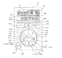
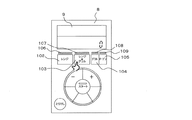
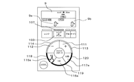
次に、図3は、実施の形態1における加熱調理器の操作部8及び表示部9の説明図である。
操作部8は、略長方形状であり、第1の操作入力領域101と第2の操作入力領域110と第3の操作入力領域123と表示部9を有する。
図3において、表示部9は液晶からなる略長方形状の表示画面であり、固定の文字と記号により、操作部8への操作入力の状態と調理状況を表示する。
Next, FIG. 3 is explanatory drawing of the operation part 8 and the display part 9 of the heating cooker in Embodiment 1. FIG.
The operation unit 8 has a substantially rectangular shape, and includes a first operation input region 101, a second operation input region 110, a third operation input region 123, and a display unit 9.
In FIG. 3, the display unit 9 is a substantially rectangular display screen made of liquid crystal, and displays the state of operation input to the operation unit 8 and the cooking status using fixed characters and symbols.

また、表示部9内は、表示の上側略半分に、「自動」や「手動」、「あたため」や「ゆでもの」や「解凍」や「のみもの」、用いる加熱手段や加熱状態などの加熱動作モードを示す表示が配置され、下側略半分には、マイクロ波を使用した加熱時の加熱時間を表示するレンジ加熱時間表示エリア9aと、各種ヒーター加熱時の加熱時間を表示するヒーター加熱時間表示エリア9bがそれぞれ設けられている。
また、このふたつの時間表示エリアは、隣り合うエリアとエリアとの間に仕切り線9cを設ける(表示する)ことにより、別々の加熱手段の為の時間が表示されるエリアであることを認識しやすいように仕切られている。
In the display unit 9, heating is performed in the upper half of the display, such as “automatic”, “manual”, “warm”, “boiled”, “thaw”, “things”, heating means to be used and heating state. A display indicating the operation mode is arranged, and in the lower half, a range heating time display area 9a for displaying the heating time at the time of heating using microwaves, and a heater heating time for displaying the heating time at the time of heating various heaters A display area 9b is provided.
In addition, by providing (displaying) a partition line 9c between the adjacent areas, the two time display areas recognize that the time for separate heating means is displayed. It is partitioned for easy.

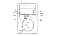
表示部9の下側の領域には、加熱手段を選択する第1の操作入力領域101が設けられている。
この第1の操作入力領域101は、レンジキー102と、レンジグリルキー103と、グリルキー104と、オーブンキー105と、前記各キーの上側に配置された発光部106、発光部107、発光部108、発光部109が配置されている。
A first operation input area 101 for selecting a heating means is provided in the lower area of the display unit 9.
The first operation input area 101 includes a range key 102, a range grill key 103, a grill key 104, an oven key 105, and a light emitting unit 106, a light emitting unit 107, and a light emitting unit 108 arranged above each key. The light emitting unit 109 is disposed.

第1の操作入力領域101の各キーは加熱手段の選択を行うものであり、レンジキー102はマグネトロン38によるマイクロ波加熱を用いたレンジ調理の選択、レンジグリルキー103はマイクロ波加熱のレンジ調理の後にフラットヒーター18および背面ガラス管ヒーター31のグリル調理を連続して行うレンジグリル調理の選択、グリルキー104はグリル調理の選択、オーブンキー105はフラットヒーター18とシーズヒーター22の加熱によるオーブン調理の選択を行う。   Each key of the first operation input area 101 is used to select a heating means, the range key 102 is used to select range cooking using microwave heating by the magnetron 38, and the range grill key 103 is used for microwave cooking range cooking. After that, the selection of the range grill cooking in which the flat heater 18 and the rear glass tube heater 31 are continuously grilled, the grill key 104 is selected for grill cooking, the oven key 105 is the oven cooking by heating the flat heater 18 and the sheathed heater 22 Make a selection.

これらの加熱手段の選択を行う加熱手段選択手段である各キーは、左から、レンジキー102、レンジグリルキー103、グリルキー104、オーブンキー105の順番で横一列となるように配列されている。
また、レンジキー102はレンジ加熱時間表示エリア9aの近傍(下側)に、グリルキー104とオーブンキー105はヒーター加熱時間表示エリア9bの近傍(下側)に、マイクロ波加熱とヒーター加熱の双方を行うレンジグリルキー103は、グリルキー104とオーブンキー105との間に挟まれて位置している。つまり、加熱手段の選択を行う各キーは、各々の加熱時間表示エリアに対応して配置されている。
The keys, which are the heating means selection means for selecting these heating means, are arranged in a horizontal row in the order of the range key 102, the range grill key 103, the grill key 104, and the oven key 105 from the left.
In addition, the range key 102 is near (lower side) the range heating time display area 9a, and the grill key 104 and the oven key 105 are both near the heater heating time display area 9b (lower side). The range grill key 103 to be performed is located between the grill key 104 and the oven key 105. That is, each key for selecting the heating means is arranged corresponding to each heating time display area.

また、これらの発光部106、107、108、109も、横方向に一列に配置されており、ドア4を開閉した際の初期状態で点灯し、キー102、103、104、105のいずれかが選択された場合に、その選択された加熱手段に対応したキーの発光部のみが点灯し、他の発光部が消灯するように構成されている。   The light emitting units 106, 107, 108, and 109 are also arranged in a row in the horizontal direction, and light up in an initial state when the door 4 is opened and closed, and any one of the keys 102, 103, 104, and 105 is turned on. When selected, only the light emitting part of the key corresponding to the selected heating means is turned on, and the other light emitting parts are turned off.

尚、発光部106はレンジキー102の上方に位置し、発光部107はレンジグリルキー103の上方に位置し、発光部108はグリルキー104の上方に位置し、発光部109はオーブンキー105の上方に位置し、それぞれのキーに対応した位置関係となるように配置されている。
このように、第1の操作入力領域101は上記の各キー群の配列により、略長方形状に形成されている。
The light emitting unit 106 is located above the range key 102, the light emitting unit 107 is located above the range grill key 103, the light emitting unit 108 is located above the grill key 104, and the light emitting unit 109 is located above the oven key 105. Are arranged so as to have a positional relationship corresponding to each key.
Thus, the first operation input area 101 is formed in a substantially rectangular shape by the arrangement of each key group described above.

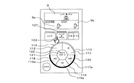
次に、第1の操作入力領域101の下側の離間した位置には、第2の操作入力領域110が設けられている。
この第2の操作入力領域110は、各加熱手段が選択された際に、調理の仕上がりに関わる加熱の強さを調節する2つの仕上がり調節キー(プラスキー111、マイナスキー112)と、加熱時間を設定する3つの加熱時間設定キー115、116、117と、調理を開始するスタートキー121から構成されている。また、これらキーに対応して設けられる発光部113、114、118、119、120、122が設けられている。
尚、第2の操作入力領域110は、これらのキーの配置により、略円形状に形成されている。
Next, a second operation input area 110 is provided at a spaced position below the first operation input area 101.
The second operation input area 110 includes two finish adjustment keys (plus key 111, minus key 112) for adjusting the intensity of heating related to the finish of cooking when each heating means is selected, and the heating time. Are comprised of three heating time setting keys 115, 116, and 117 for setting cooking, and a start key 121 for starting cooking. In addition, light emitting units 113, 114, 118, 119, 120, and 122 provided corresponding to these keys are provided.
The second operation input area 110 is formed in a substantially circular shape by the arrangement of these keys.

次に、第2の操作入力領域110の各キーを説明すると、まず、仕上がり調節キーは、調理物5の調理の仕上がり具合を上げるプラスキー111と、仕上がり具合を下げるマイナスキー112からなる。仕上がり具合とは、仕上がり状態の調理物5の温度や焼目の具合や量などのことである。
また、これらの仕上がり調節キーの形状は、中心から所定の半径の領域が切り欠かれた開角が略90度の扇形状である。
Next, each key in the second operation input area 110 will be described. First, the finish adjustment key includes a plus key 111 for raising the degree of cooking of the food 5 and a minus key 112 for lowering the degree of finishing. The finished condition refers to the temperature of the cooked food 5 in the finished state, the degree and amount of grilling, and the like.
Further, the shape of these finish adjustment keys is a fan shape having an opening angle of approximately 90 degrees with a predetermined radius area cut away from the center.

次に、加熱時間設定キーは、加熱時間を任意に設定する際に用いるものであり、設定可能な時間の単位の大きさに応じて、第1の加熱時間設定キー115、第2の加熱時間設定キー116、第3の加熱時間設定キー117から構成されている。
これらの各設定キーは、選択した加熱手段に応じて、設定可能な時間の単位(時間の幅)がそれぞれ変化するように構成されている。つまり、加熱時間設定キーは、選択された加熱手段の加熱特性に応じて、各キーに記載された(5分など)文字の裏面に各々設けられた光源となるLEDのうち、設定可能な時間の単位(5分など)に該当する文字のみを点灯させるように構成されており、入力値が変更されるように構成されている。
Next, the heating time setting key is used to arbitrarily set the heating time, and the first heating time setting key 115 and the second heating time are set according to the settable time unit size. It consists of a setting key 116 and a third heating time setting key 117.
Each of these setting keys is configured such that a settable time unit (time width) changes according to the selected heating means. In other words, the heating time setting key is a settable time among the LEDs serving as light sources provided on the back side of the characters (such as 5 minutes) described in each key according to the heating characteristics of the selected heating means. It is configured to light only the characters corresponding to the unit (such as 5 minutes), and the input value is changed.

例えば、マイクロ波を用いるレンジ加熱の場合、第1の加熱時間設定キー115は5分単位で時間設定入力を行うことができる5分キー115aとなり、第2の加熱時間設定キー116は1分単位で時間設定入力を行うことができる1分キー116aとなり、第3の加熱時間設定キー117は10秒単位で時間設定入力が行うことができる10秒キー117aとなる。
また、各種ヒーターを用いて行うヒーター加熱の場合、第1の加熱時間設定キー115は10分単位で時間設定入力を行うことができる10分キー115bとなり、第2の加熱時間設定キー116は5分単位で時間設定入力を行うことができる5分キー116bとなり、第3の加熱時間設定キー117は1分単位で時間設定入力が行うことができる1分キー117bとなる。
For example, in the case of range heating using microwaves, the first heating time setting key 115 is a 5-minute key 115a that allows time setting input in units of 5 minutes, and the second heating time setting key 116 is in units of 1 minute. The 1-minute key 116a can be used to input a time setting, and the third heating time setting key 117 is a 10-second key 117a that can be used to input a time setting in units of 10 seconds.
Further, in the case of heater heating using various heaters, the first heating time setting key 115 becomes a 10 minute key 115b that allows time setting input in units of 10 minutes, and the second heating time setting key 116 is 5 The 5-minute key 116b can be used to input a time setting in units of minutes, and the third heating time setting key 117 can be a 1-minute key 117b that can be used to input time settings in units of 1 minute.

また、これらの加熱時間設定キーの形状は、中心から所定の半径の領域が切り欠かれた開角が略60度の扇形状である。
尚、仕上がり調節キーと加熱時間設定キーをなす扇形状のキーは、全て同じ半径で構成されており、また、切り欠かれた部分の領域の半径も同じである。
These heating time setting keys have a fan shape with an opening angle of approximately 60 degrees, in which a region having a predetermined radius is cut from the center.
Note that the fan-shaped keys that form the finish adjustment key and the heating time setting key are all configured with the same radius, and the radius of the notched region is also the same.

次に、スタートキー121は、第1の操作入力領域101又は仕上がり調節キー又は加熱時間設定キーにより各種設定を行った後、加熱調理を開始するためのキーである。このスタートキー121は、円形状に構成されており、この円の半径は仕上がり調節キーや加熱時間設定キーの切り欠かれた部分の領域の半径よりも小さい。
また、スタートキー121には、キー入力が可能な場合に点滅する発光部122が設けられている。
Next, the start key 121 is a key for starting cooking by performing various settings using the first operation input area 101, the finish adjustment key, or the heating time setting key. The start key 121 is formed in a circular shape, and the radius of the circle is smaller than the radius of the region where the finish adjustment key and the heating time setting key are notched.
In addition, the start key 121 is provided with a light emitting unit 122 that blinks when key input is possible.

以上のように構成された第2の操作入力領域110を構成するキーは、次のように配置される。
まず、プラスキー111とマイナスキー112と第1の加熱時間設定キー115と第2の加熱時間設定キー116と第3の加熱時間設定キー117は、各キーの直線部分を隣り合わせて配置される。つまり、プラスキー111とマイナスキー112は開角が略90度であり、第1の加熱時間設定キー115と第2の加熱時間設定キー116と第3の加熱時間設定キー117は開角が略60であり、各キーをなす扇形状は全て同じ半径であり、また、それぞれ切り欠かれた部分の領域の半径も同じであることから、これらのキーの配列によりリング形状が形成される。
The keys constituting the second operation input area 110 configured as described above are arranged as follows.
First, the plus key 111, the minus key 112, the first heating time setting key 115, the second heating time setting key 116, and the third heating time setting key 117 are arranged so that the linear portions of the keys are adjacent to each other. That is, the plus key 111 and the minus key 112 have an opening angle of approximately 90 degrees, and the first heating time setting key 115, the second heating time setting key 116, and the third heating time setting key 117 have an opening angle of approximately 90 degrees. 60, all the fan shapes forming the respective keys have the same radius, and the radii of the regions of the cutout portions are also the same, so that a ring shape is formed by the arrangement of these keys.

そして、このリング形状の中心となる位置に、スタートキー121が配置され、第2の操作入力領域110は、これらのキーの配置により、円形状(円盤状)に形成される。
尚、マイナスキー112とプラスキー111は、第2の操作入力領域110の上半分に配置され、左側にマイナスキー112、右側にプラスキー111が位置する。
The start key 121 is arranged at the center of the ring shape, and the second operation input area 110 is formed in a circular shape (disk shape) by the arrangement of these keys.
The minus key 112 and the plus key 111 are arranged in the upper half of the second operation input area 110, and the minus key 112 is located on the left side and the plus key 111 is located on the right side.

また、第1の加熱時間設定キー115と第2の加熱時間設定キー116と第3の加熱時間設定キー117は、第2の操作入力領域110の下半分に配置される。
特に、設定可能な時間の単位が一番大きい第1の加熱時間設定キー115は左側に、設定可能な時間の単位が2番目の大きさである第2の加熱時間設定キー116は中央に、設定可能な時間の単位が最も小さい単位である第3の加熱時間設定キー117は右側にそれぞれ位置するように配置される。
また、仕上がり調節キー及び加熱時間設定キーのそれぞれのキーの外周部には、キー入力が可能な場合に点灯する発光部113、発光部114、発光部118、発光部119、発光部120が配置されている。
The first heating time setting key 115, the second heating time setting key 116, and the third heating time setting key 117 are arranged in the lower half of the second operation input area 110.
In particular, the first heating time setting key 115 having the largest settable time unit is on the left side, and the second heating time setting key 116 having the second settable time unit is on the center. The third heating time setting key 117, which is the smallest unit of time that can be set, is arranged to be located on the right side.
In addition, a light-emitting unit 113, a light-emitting unit 114, a light-emitting unit 118, a light-emitting unit 119, and a light-emitting unit 120 that are turned on when key input is possible are arranged on the outer periphery of each of the finish adjustment key and the heating time setting key Has been.

次に、第2の操作入力領域110の左下側の離間した位置には、第3の操作入力領域123が形成されており、領域内部に第1の操作入力領域101及び第2の操作入力領域110で行った操作入力を解除する円形状の取消しキー124が配置されている。
この第3の操作入力領域123は、略長方形状である操作部8の下辺8aと、この下辺8aに略垂直に交わる左辺8bと、円形状である第2の操作入力領域110に囲まれている。
Next, a third operation input area 123 is formed at a position separated from the lower left side of the second operation input area 110, and the first operation input area 101 and the second operation input area are formed inside the area. A circular cancel key 124 for canceling the operation input performed at 110 is arranged.
The third operation input area 123 is surrounded by a lower side 8a of the operation unit 8 that is substantially rectangular, a left side 8b that intersects the lower side 8a substantially perpendicularly, and a second operation input area 110 that is circular. Yes.

ここで、操作部8における第2の操作入力領域110の占める割合が大きくなり、第2の操作入力領域110が操作部8の下辺8aと左辺8bに近づいても、第2の操作入力領域110は円形状であるので、第2の操作入力領域110と下辺8aと左辺8bに囲まれた部分には隙間が形成される。
従って、操作部8における第2の操作入力領域110の占める割合が大きくなっても、取消しキー124を設けるスペースを確保することができる。
Here, even if the proportion of the second operation input area 110 in the operation unit 8 increases and the second operation input area 110 approaches the lower side 8a and the left side 8b of the operation unit 8, the second operation input area 110 is displayed. Is a circular shape, a gap is formed in a portion surrounded by the second operation input region 110, the lower side 8a, and the left side 8b.
Therefore, even if the proportion of the second operation input area 110 in the operation unit 8 increases, a space for providing the cancel key 124 can be secured.

操作部8は、以上のように構成されており、操作者が操作を行う際の手順として、まず加熱手段を選択することが明確であるため、操作者が調理物5を調理するのに適した加熱手段を選択しやすい。
また、第2の操作入力領域110に仕上がり調節キーと加熱時間設定キーとスタートキー121が1つの纏りになって第1の操作入力領域101の下側に配置されているので、加熱手段の選択の後にこれらの操作を行うという操作手順を理解し易い。
The operation unit 8 is configured as described above, and since it is clear that the heating means is first selected as a procedure when the operator performs the operation, the operation unit 8 is suitable for the operator to cook the food 5. Easy to select the heating means.
In addition, since the finish adjustment key, the heating time setting key, and the start key 121 are arranged together in the second operation input area 110 under the first operation input area 101, the heating means It is easy to understand the operation procedure of performing these operations after selection.

取消しキー124は第1の操作入力領域101、および第2の操作入力領域110から離れた位置に独立して配置されているため、認識し易く、どの操作入力ステップにおいても容易に操作を行うことができる。また、操作部8においてグリルキー104とオーブンキー105を一つの領域にまとめながら、2つのキーとして配置することにより、グリル調理とオーブン調理がヒーターによる加熱手段を利用する点で共通することを理解し易くしている。   Since the cancel key 124 is independently arranged at a position away from the first operation input area 101 and the second operation input area 110, it is easy to recognize and can be easily operated at any operation input step. Can do. In addition, it is understood that the grill cooking and the oven cooking use the heating means by the heater by arranging the grill key 104 and the oven key 105 as two keys while combining them in one area in the operation unit 8. It is easy.

本実施の形態1の加熱調理器は、調理物5を加熱する加熱源として、マイクロ波による加熱手段と、ヒーター(フラットヒーター18、背面ガラス管ヒーター31、シーズヒーター22)の加熱手段を有し、また、加熱方法として、レンジ調理と、グリル調理と、オーブン調理と、レンジ調理とグリル調理の複合調理であるレンジグリル調理の4通りの加熱方法を有する。   The heating cooker according to the first embodiment has a heating means using microwaves and a heating means for heaters (flat heater 18, back glass tube heater 31, sheathed heater 22) as a heating source for heating cooked food 5. As heating methods, there are four heating methods: range cooking, grill cooking, oven cooking, and range grill cooking which is a combined cooking of range cooking and grill cooking.

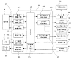
図4は、実施の形態1における加熱調理器の制御ブロック図である。以上のとおり、操作手順と発光部の点灯状況を説明したが、これらの操作は、制御部44のキー入力判定手段46によって、マイコン45取り込まれ、入力されたキーに応じた表示を表示駆動手段47により、LEDの点灯制御をLED駆動手段48により行なっている。
調理方法を設定した後、スタートキー121を押下することにより、加熱調理が開始される。調理が開始されると、手動レンジ調理の場合、マイコン45は、モーター駆動手段50によりアンテナモーター25を駆動するとともに、マグネトロン駆動手段43を介してインバーター基板39を駆動してマグネトロン38を発振させ、加熱を開始する。設定された出力で、設定された時間加熱を継続しながら、表示部9で調理時間をカウントダウンし、設定された時間加熱をした時点で加熱を停止し、表示部9に調理終了である旨を表示するとともに、報知手段52により例えばブザー音で調理終了を報知する。
FIG. 4 is a control block diagram of the heating cooker in the first embodiment. As described above, the operation procedure and the lighting state of the light emitting unit have been described. These operations are captured by the microcomputer 45 by the key input determination unit 46 of the control unit 44, and display according to the input key is displayed. 47, LED lighting control is performed by the LED driving means 48.
After setting the cooking method, the cooking is started by pressing the start key 121. When cooking is started, in the case of manual range cooking, the microcomputer 45 drives the antenna motor 25 by the motor driving means 50 and drives the inverter board 39 via the magnetron driving means 43 to oscillate the magnetron 38. Start heating. While continuing the heating for the set time with the set output, the cooking time is counted down on the display unit 9, the heating is stopped when the set time is heated, and the display unit 9 indicates that the cooking is finished. At the same time, the notification means 52 notifies the end of cooking with a buzzer sound, for example.

一方、自動のレンジ調理の場合には、加熱室2の外側に設けられた調理物5の表面温度を検出する赤外線センサー41と、加熱室2内の温度を検出するサーミスタ42が設けられており、自動調理においては、これらの検知結果に基づき、加熱時間を調節し、調理制御が行われる。なお、本実施の形態1に係る加熱調理器のサーミスタ42は、調理物5より発生する蒸気を微小な温度変化として捉えて検出することで、蒸気検出器としての機能も併せ持っている。
また、オーブン調理やグリル調理の場合には、設定された調理に応じて、ヒーター駆動手段49により、フラットヒーター18やシーズヒーター22、背面ガラス管ヒーター31を駆動したり、場合によってはファンモーター駆動手段51によりファンモーター36を回転させることで加熱室2内の熱風を循環させて加熱を行い、サーミスタ42の検知結果に基づき、調理制御が行われる。
On the other hand, in the case of automatic range cooking, an infrared sensor 41 for detecting the surface temperature of the food 5 provided outside the heating chamber 2 and a thermistor 42 for detecting the temperature in the heating chamber 2 are provided. In automatic cooking, cooking time is controlled by adjusting the heating time based on these detection results. The thermistor 42 of the heating cooker according to the first embodiment also has a function as a steam detector by detecting and detecting the steam generated from the food 5 as a minute temperature change.
In the case of oven cooking or grill cooking, the heater heater 49 drives the flat heater 18, the sheathed heater 22, and the back glass tube heater 31 according to the set cooking, or in some cases, a fan motor drive. The fan motor 36 is rotated by the means 51 to circulate the hot air in the heating chamber 2 for heating, and cooking control is performed based on the detection result of the thermistor 42.

次に、調理を行う場合の操作手順について説明する。
本実施の形態1に係る加熱調理器は、上記のようにレンジ調理と、グリル調理と、オーブン調理と、レンジ調理とグリル調理の複合調理であるレンジグリル調理の4通りの加熱方法を有する。
この中で、マイクロ波加熱によるレンジ調理の後に、フラットヒーター18と背面ガラス管ヒーター31を同時通電するグリル調理を連続して行うレンジグリル調理を選択した場合の操作手順を説明する。
Next, an operation procedure when cooking is described.
As described above, the cooking device according to the first embodiment has four heating methods of range cooking, grill cooking, oven cooking, and range grill cooking, which is combined cooking of range cooking and grill cooking.
In this description, the operation procedure when range grill cooking in which grill cooking in which the flat heater 18 and the rear glass tube heater 31 are energized continuously is selected after range cooking by microwave heating will be described.

<レンジグリル調理時の自動モードの操作手順>
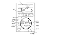
図5A〜図5Cは、実施の形態1に係る加熱調理器でレンジグリル調理における機能切り替えの操作手順と発光部の点灯状況、および表示部の表示内容を示した説明図である。
<Operation procedure of automatic mode when cooking range grill>
FIG. 5A to FIG. 5C are explanatory diagrams showing the function switching operation procedure, the lighting state of the light emitting unit, and the display content of the display unit in range grill cooking by the heating cooker according to the first embodiment.

図5Aは、調理物5を加熱室2の調理プレート6上に載置してドア4を閉じた初期状態の操作部8の状態であり、表示部9には「0」が表示され、レンジキー102と、レンジグリルキー103と、グリルキー104と、オーブンキー105の各キーに対応した発光部106、発光部107、発光部108、発光部109が点灯し、加熱手段を選択する4つのキーが有効であることを示している。   FIG. 5A shows a state of the operation unit 8 in an initial state in which the food 5 is placed on the cooking plate 6 of the heating chamber 2 and the door 4 is closed, and “0” is displayed on the display unit 9 and the range is displayed. The light emitting unit 106, the light emitting unit 107, the light emitting unit 108, and the light emitting unit 109 corresponding to the keys 102, the range grill key 103, the grill key 104, and the oven key 105 are turned on, and four keys for selecting a heating means are selected. Is valid.

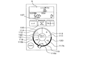
図5Aにおいて、レンジグリルキー103を1回押下した場合、図5Bの状態となる。レンジグリルキー103に対応する発光部107は、点灯を継続し、他の発光部106、108、109は消灯に変わり、レンジグリル調理のモードに入ったことを示す。
表示部9には「レンジ→グリル」が表示され、レンジグリル調理の選択であることが示され、「自動」のモード表示となる。
In FIG. 5A, when the range grill key 103 is pressed once, the state shown in FIG. 5B is obtained. The light emitting unit 107 corresponding to the range grill key 103 continues to be lit, and the other light emitting units 106, 108, 109 are turned off to indicate that the range grill cooking mode has been entered.
“Range → Grill” is displayed on the display unit 9 to indicate that range grill cooking is selected, and an “automatic” mode display is displayed.

レンジグリル調理において、レンジ調理のステップでは、レンジ出力は600Wで固定され、レンジ調理からグリル調理に自動的に移行するタイミングは、加熱室2に設けられた加熱室2内の温度を検出する加熱室温度検出器であるサーミスタ42、調理物5の発する蒸気量を検出する蒸気検出器(本実施の形態においてはサーミスタ42)、調理物5の温度を非接触で検出する非接触温度検出器である赤外線センサー41などによって検出された調理物5の加熱状況によって決定される。
また、グリル調理のステップに移行した後のヒーター加熱による加熱時間は、加熱中の加熱室2の温度変化によって決定されるが、使用者の好みに応じて調理の仕上がりの強弱レベルによって加減することができる。
In the range grill cooking, in the range cooking step, the range output is fixed at 600 W, and the timing for automatically shifting from the range cooking to the grill cooking is the heating for detecting the temperature in the heating chamber 2 provided in the heating chamber 2. A thermistor 42 which is a room temperature detector, a steam detector (thermistor 42 in the present embodiment) for detecting the amount of steam emitted from the food 5, and a non-contact temperature detector for detecting the temperature of the food 5 in a non-contact manner. It is determined by the heating status of the food 5 detected by an infrared sensor 41 or the like.
In addition, the heating time by the heater heating after the transition to the grill cooking step is determined by the temperature change of the heating chamber 2 during heating, but it is adjusted depending on the level of cooking finish according to the user's preference. Can do.

レンジグリル調理の「自動」モードを選択した状態で、表示部9には初期設定時の強弱レベル「3」が表示され、発光部122が点滅し、スタートキー121が有効であることが示される。
また、発光部114と発光部113も点灯し、初期設定時の温度をプラスキー111とマイナスキー112によって仕上がりレベル(焼き色)を変更できることも示される。
In the state where the “automatic” mode of range grill cooking is selected, the strength level “3” at the initial setting is displayed on the display unit 9, the light emitting unit 122 blinks, and the start key 121 is effective. .
In addition, the light-emitting unit 114 and the light-emitting unit 113 are also turned on, and it is also shown that the temperature at the initial setting can be changed by the plus key 111 and the minus key 112.

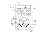
図5Bにおいて、レンジグリルキー103をもう1回押下した場合、図5Cの状態となる。
発光部107は点灯を継続し、レンジグリル調理のモードであることを示す。表示部9は「手動」のモード表示となる。ここで、レンジ調理のステップでの設定可能項目はレンジ加熱時間のみであり、レンジ出力は600Wで固定となる。また、グリル調理のステップでの調節可能項目は加熱時間のみとなる。
In FIG. 5B, when the range grill key 103 is pressed again, the state shown in FIG. 5C is obtained.
The light emitting unit 107 continues to be lit, indicating that it is in the range grill cooking mode. The display unit 9 displays the “manual” mode. Here, the settable item in the range cooking step is only the range heating time, and the range output is fixed at 600W. The adjustable item in the grill cooking step is only the heating time.

この状態において、表示部9のレンジ加熱時間表示エリア9aには、レンジ加熱時間t1’の設定値として初期値の「0秒」が表示され、ヒーター加熱時間表示エリア9bには、グリル加熱時間t2’の初期値である「0秒」が表示され、連続加熱する双方の加熱モードでの加熱時間が両方同時に表示されている。   In this state, the initial value “0 second” is displayed as the set value of the range heating time t1 ′ in the range heating time display area 9a of the display unit 9, and the grill heating time t2 is displayed in the heater heating time display area 9b. The initial value of “0 seconds” is displayed, and both heating times in both heating modes for continuous heating are displayed at the same time.

また、発光部118、発光部119、発光部120が点滅するとともに、レンジ時間表示用LEDが各々点灯し、加熱時間設定キー各々に入力できる時間が表示され、5分キー115aと1分キー116aと10秒キー117aによるレンジ加熱時間の設定が促される。レンジグリル調理の手動モードでは、レンジ加熱時間t1’とグリル加熱時間t2’の設定は必須の操作であり、設定がされなければ調理が開始されない。
従って、加熱時間が設定されるまで、スタートキー121は有効とならず、発光部122は点滅しない。
In addition, the light emitting unit 118, the light emitting unit 119, and the light emitting unit 120 blink, the range time display LEDs are turned on, and the time that can be input to each heating time setting key is displayed, and the 5 minute key 115a and the 1 minute key 116a. And the setting of the range heating time by the 10-second key 117a is prompted. In the manual mode of the range grill cooking, the setting of the range heating time t1 ′ and the grill heating time t2 ′ is an essential operation, and cooking is not started unless they are set.
Therefore, until the heating time is set, the start key 121 is not effective and the light emitting unit 122 does not blink.

以上のレンジ加熱時間とグリル加熱時間の調理設定を行った後、スタートキー121を押下することにより、加熱調理が開始される。
尚、図5Cにおいて、レンジグリルキー103をさらに1回押下すると、図5Bの状態である「レンジグリル調理の自動」に戻る。
After the cooking setting of the above range heating time and grill heating time is performed, by pressing the start key 121, heating cooking is started.
In FIG. 5C, when the range grill key 103 is further pressed once, the state returns to the “automatic range grill cooking” state shown in FIG. 5B.

<レンジグリル調理時の手動モードの操作手順>
次に、レンジグリル調理の「手動」モードを使用する際の操作手順について説明する。
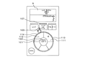
図6A〜図6Eは、実施の形態1に係る加熱調理器におけるレンジグリル調理の「手動」のモードを使用する場合の操作手順と発光部の点灯状況、及び、表示部の表示内容を示した説明図である。
<Operation procedure in manual mode when cooking range grill>
Next, an operation procedure when using the “manual” mode of range grill cooking will be described.
6A to 6E show the operation procedure, the lighting state of the light emitting unit, and the display content of the display unit when using the “manual” mode of range grill cooking in the heating cooker according to the first embodiment. It is explanatory drawing.

図6Aは調理物5を加熱室2の調理プレート6上に載置してドア4を閉じた初期状態の操作部8の状態であり、表示部9には0が表示され、レンジキー102と、レンジグリルキー103と、グリルキー104と、オーブンキー105の各キーに対応した発光部106、発光部107、発光部108、発光部109が点灯し、加熱手段を選択する4つのキーが有効であることを示している。   6A shows a state of the operation unit 8 in an initial state in which the food 5 is placed on the cooking plate 6 of the heating chamber 2 and the door 4 is closed, and 0 is displayed on the display unit 9, and the range key 102 and The light emitting unit 106, the light emitting unit 107, the light emitting unit 108, and the light emitting unit 109 corresponding to each of the range grill key 103, the grill key 104, and the oven key 105 are turned on, and four keys for selecting a heating means are effective. It shows that there is.

図6Aにおいて、レンジグリルキー103を2回押下した場合、図6Bの状態となる。
発光部107は、点灯を継続し、他の発光部106、108、109は消灯に変わり、レンジグリル調理のモードに入ったことを示す。表示部9には「レンジ→グリル」が表示され、レンジグリル調理の選択であることが示され、「手動」のモード表示となる。発光部118、発光部119、発光部120が点滅するとともに、レンジ時間表示用LEDが各々点灯し、加熱時間設定キー各々に入力できる時間が表示され、5分キー115aと1分キー116aと10秒キー117aによるレンジ加熱時間t1’の設定が促される。
In FIG. 6A, when the range grill key 103 is pressed twice, the state shown in FIG. 6B is obtained.
The light emitting unit 107 continues to be lit, and the other light emitting units 106, 108, and 109 are turned off to indicate that the range grill cooking mode has been entered. “Range → Grill” is displayed on the display unit 9 to indicate that the range grill cooking is selected, and the mode display is “Manual”. The light-emitting unit 118, the light-emitting unit 119, and the light-emitting unit 120 blink, the range time display LEDs are lit, and the time that can be input to each heating time setting key is displayed. The 5-minute key 115a and the 1-minute keys 116a and 10 Setting of the range heating time t1 ′ by the second key 117a is prompted.

そして、表示部9の下段の左側に設けられたレンジ加熱時間表示エリア9aには、レンジ加熱時間t1’の設定値として初期値の「0秒」が表示され、右側のヒーター加熱時間表示エリア9bにはグリル加熱時間t2’の初期値である「0秒」が表示される。また、仕切り線9cは、レンジ調理とグリル調理の双方が連続して行われることを使用者が理解しやすいように、表示させていない。   In the range heating time display area 9a provided on the lower left side of the display unit 9, the initial value “0 seconds” is displayed as the set value of the range heating time t1 ′, and the heater heating time display area 9b on the right side is displayed. Displays “0 second”, which is the initial value of the grill heating time t2 ′. The partition line 9c is not displayed so that the user can easily understand that both range cooking and grill cooking are performed continuously.

次に、図6Bにおいて、5分キー115aを1回押下すると、図6Cの状態となる。表示部9のレンジ加熱時間表示エリア9aに表示されたレンジ加熱時間t1’の表示が5分加えられて「5分00秒」となる。
ここで、レンジ加熱時間t1’が設定されたため、次のステップ、すなわちグリル加熱時間t2’の設定ステップへの切り替え操作であるプラスキー111の設定操作を促すべく、発光部113が点滅する。
Next, in FIG. 6B, when the 5-minute key 115a is pressed once, the state shown in FIG. 6C is obtained. The display of the range heating time t1 ′ displayed in the range heating time display area 9a of the display unit 9 is added for 5 minutes to become “5:00 minutes 00 seconds”.
Here, since the range heating time t1 ′ has been set, the light emitting unit 113 blinks in order to prompt the setting operation of the plus key 111 which is a switching operation to the next step, that is, the setting step of the grill heating time t2 ′.

発光部113は、点滅状態を継続し、プラスキー111の押下を促し続けるが、一定時間(例えば5秒)経過しても、プラスキー111の押下などのキー操作が無い場合、よりいっそうプラスキー111の設定操作を促すように、5分キー115aと1分キー116aと10秒キー117aの各発光部118,119,120を消灯するとともに、発光部113の輝度を高くして点滅させ、プラスキー111への注目度を高めるようになっている。この時、発光部113は、LEDと直列に接続された負荷抵抗を小さな抵抗値に切り替えて、流れる電流を増やすことで輝度を高くする。   The light emitting unit 113 continues to blink and continues to prompt the user to press the plus key 111. However, if there is no key operation such as pressing the plus key 111 after a certain time (for example, 5 seconds), the plus key 111 is further increased. In order to prompt the setting operation 111, the light emitting units 118, 119, and 120 of the 5-minute key 115a, the 1-minute key 116a, and the 10-second key 117a are turned off, and the luminance of the light-emitting unit 113 is increased and blinked. The degree of attention to the key 111 is increased. At this time, the light emitting unit 113 increases the luminance by switching the load resistance connected in series with the LED to a small resistance value and increasing the flowing current.

尚、この状態でも5分キー115aと1分キー116aと10秒キー117aによるレンジ加熱時間の設定の変更を行うことができるように構成されている。また、本実施の形態では、発光部113の輝度を高くする例を挙げているが、発光部113の発行色を変化させたりして注目度を高くしてもよい。   In this state, the range heating time setting can be changed by the 5-minute key 115a, the 1-minute key 116a, and the 10-second key 117a. In the present embodiment, an example is given in which the luminance of the light emitting unit 113 is increased. However, the attention level may be increased by changing the issue color of the light emitting unit 113.

次に、プラスキー111が押下されると、図6Dのグリル調理時間の設定ステップとなる。発光部118、発光部119、発光部120が点滅するとともに、ヒーター時間表示用LEDが各々点灯し、加熱時間設定キー各々に入力できる時間が表示され、10分キー115bと5分キー116bと1分キー117bによるグリル加熱時間t2’の設定が促される。   Next, when the plus key 111 is pressed, the grill cooking time setting step in FIG. 6D is performed. The light-emitting unit 118, the light-emitting unit 119, and the light-emitting unit 120 blink, the heater time display LEDs are turned on, and the time that can be input to each heating time setting key is displayed. The 10-minute key 115b and the 5-minute key 116b and 1 Setting of the grill heating time t2 ′ by the minute key 117b is prompted.

図6Dの状態から、5分キー116bが押下されると、図6Eの状態、すなわち、ヒーター加熱時間表示エリア9bに設定されたグリル加熱時間t2’が「5分00秒」と表示されるとともに、発光部118、発光部119、発光部120は点滅から点灯に変わり、発光部122が点滅状態となり、スタートキー121が有効となる。
以上の調理設定を行った後、スタートキー121を押下することにより、加熱調理が開始される。
When the 5-minute key 116b is pressed from the state shown in FIG. 6D, the state shown in FIG. 6E, that is, the grill heating time t2 ′ set in the heater heating time display area 9b is displayed as “5:00 minutes 00 seconds”. The light emitting unit 118, the light emitting unit 119, and the light emitting unit 120 change from blinking to lighting, the light emitting unit 122 enters the blinking state, and the start key 121 is enabled.
After performing the above cooking settings, the cooking is started by pressing the start key 121.

<レンジグリル調理の手動モード時における報知、移行スキップ制御>
次に、実施の形態1に係る上記のレンジグリル調理の手動モードにおける制御について説明する。
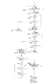
図7は、実施の形態1に係るレンジグリル調理の手動モード時におけるレンジ調理時の報知、移行スキップ制御を示す制御フロー図である。
<Notification in range grill cooking manual mode, transition skip control>
Next, the control in the manual mode of the range grill cooking according to the first embodiment will be described.
FIG. 7 is a control flow diagram showing notification and shift skip control during range cooking in the manual mode of range grill cooking according to the first embodiment.

はじめにステップ1にてドア4が開くと、ステップ2にて電源をオンする。次にステップ3にて手動モードが選択されたか否かを判断する。手動モードの場合にはステップ4に進み、レンジ加熱時間t1’とグリル加熱時間t2’の両方が設定された時点でステップ5に進む。
ここで、ステップ4においてレンジ加熱時間t1’を180秒、グリル加熱時間t2’を600秒とした例を説明する。
ステップ5にてレンジの出力を600Wに固定し、計時手段のカウンターt1を初期値であるゼロにセットする。なお、レンジ加熱時間の最大値t1maxは、例えば300秒に設定される。
First, when the door 4 is opened in step 1, the power is turned on in step 2. Next, in step 3, it is determined whether or not the manual mode is selected. In the case of the manual mode, the process proceeds to Step 4 and proceeds to Step 5 when both the range heating time t1 ′ and the grill heating time t2 ′ are set.
Here, an example in which the range heating time t1 ′ is 180 seconds and the grill heating time t2 ′ is 600 seconds in step 4 will be described.
In step 5, the output of the range is fixed to 600 W, and the counter t1 of the time measuring means is set to the initial value zero. In addition, the maximum value t1max of the range heating time is set to 300 seconds, for example.

ドア4が閉められていることをドア開閉検出手段53が検出している状態で、ステップ6で加熱がスタートすると、ステップ7にて各センサーで加熱の状態を検出する。ここでセンサーとは、加熱室2内の温度を検出する加熱室温度検出器であるサーミスタ42、調理物5の発する蒸気量を検出する蒸気検出器(本実施の形態においてはサーミスタ42)、調理物5の温度を非接触で検出する非接触温度検出器である赤外線センサー41などである。また、ステップ8にて計時手段のカウンターt1のカウントを開始する。   When the door opening / closing detection means 53 detects that the door 4 is closed and heating is started in step 6, the heating state is detected by each sensor in step 7. Here, the sensor means a thermistor 42 that is a heating chamber temperature detector that detects the temperature in the heating chamber 2, a steam detector that detects the amount of steam emitted from the food 5 (the thermistor 42 in the present embodiment), cooking An infrared sensor 41 is a non-contact temperature detector that detects the temperature of the object 5 in a non-contact manner. In step 8, the counter t1 of the time measuring means starts counting.

ステップ9にてカウンターt1の値が設定したレンジ加熱時間t1’に達したか否かを判断する。
カウンターt1の値が設定したレンジ加熱時間t1’に達した場合にはステップ10に進み、グリル加熱に移行する。設定したレンジ加熱時間t1’に達していない場合にはステップ11に進み、上記の各センサーで検出した値がグリル加熱移行用の閾値に達したかを判断する。ここでグリル加熱移行用の閾値とは、レンジ加熱が十分に達成されたか否かを判断するための目安として上記各センサーである加熱室温度検出器(サーミスタ42)で検出した温度、蒸気検出器で検出した蒸気量、非接触温度検出器(赤外線センサー41)で検出した温度等を規定した値である。
In step 9, it is determined whether or not the value of the counter t1 has reached the set range heating time t1 ′.
When the value of the counter t1 reaches the set range heating time t1 ′, the process proceeds to step 10 and shifts to grill heating. If the set range heating time t1 ′ has not been reached, the process proceeds to step 11 to determine whether the value detected by each of the sensors has reached the threshold value for grill heating transition. Here, the threshold value for transition to grill heating refers to the temperature detected by the heating chamber temperature detector (thermistor 42), which is each of the above sensors as a guide for determining whether or not range heating has been sufficiently achieved, and a steam detector. This is a value that defines the amount of steam detected in step 1, the temperature detected by the non-contact temperature detector (infrared sensor 41), and the like.

ステップ11にて各センサーで検出した値がグリル加熱移行用の閾値に達した場合には、ステップ12に進み、使用者がレンジ加熱からグリル加熱に移行する移行スキップ操作を許可するとともに、その時の計時手段のカウンターt1の時間をt1aとして記憶部に記憶し、報知手段52により報知を発報する。この報知は、設定したレンジ加熱時間t1’に計時手段のカウンターt1の値が達していない場合でも、調理物5の状態がレンジ加熱を終了する条件を満たした場合に使用者に対してレンジ加熱からグリル加熱に移行する移行スキップ操作を促すためのものである。   When the value detected by each sensor in step 11 reaches the threshold value for shifting to grill heating, the process proceeds to step 12 where the user permits a transition skip operation for shifting from range heating to grill heating, and at that time The time of the counter t1 of the time measuring means is stored in the storage unit as t1a, and the notification is issued by the notification means 52. This notification is given to the user when the state of the food 5 satisfies the condition for ending the range heating even when the value of the counter t1 of the timing means has not reached the set range heating time t1 ′. This is for urging a transition skip operation to shift to grill heating.

報知手段52による報知は、表示部9への表示やパイロットサインでの表示、報知音や音声による報知など使用者にレンジ加熱を終了する条件が満たされたことを通知するものであれば様々な手段を採用することができる。なお、報知を調理器の本体1から離れている使用者に確実に伝えるために少なくとも、音による報知を行なうことが好ましい。更に、表示部9に例えば「レンジ加熱を終了しグリル加熱に移行することが可能です。移行する場合は「+」キーを押してください。」などの表示を併用することが望ましい。また、移行スキップ操作をわかりやすくするために、この場合プラスキー111に対応する発光部113を点滅させることが望ましい。   The notification by the notification means 52 may be various as long as it notifies the user that the condition for ending the range heating is satisfied, such as display on the display unit 9, display with a pilot sign, notification by notification sound or voice. Means can be employed. In addition, it is preferable to perform at least sound notification in order to reliably transmit the notification to a user who is away from the main body 1 of the cooking device. In addition, for example, “It is possible to end the range heating and shift to grill heating. Press the“ + ”key to shift. It is desirable to use a display such as “” together. In order to make the transition skip operation easier to understand, in this case, it is desirable to blink the light emitting unit 113 corresponding to the plus key 111.

ここで、レンジ加熱からグリル加熱への移行を促す報知手段52による報知は、調理器の本体1に予め記憶された自動調理においてレンジ加熱からグリル加熱へ移行するタイミングで行なわれるよう構成されている。すなわち、自動モードとして、加熱前の初期状態で調理済みの調理物5を再加熱する自動再加熱モードと初期状態で未調理の調理物5を調理する自動調理モードというふたつのモードを備えている場合、その食品を自動再加熱モードで加熱した場合の移行タイミングで第1報知を行なうとともに、自動調理モードで過熱した場合の移行タイミングで第2報知を行なうというように、各種調理条件に応じて報知するように構成されている。そして、これらの報知はそれぞれの区別がつくように違う種類の報知(例えば、報知音の鳴動パターンが異なるなど)とすることが望ましい。   Here, the notification by the notifying means 52 urging the transition from the range heating to the grill heating is configured to be performed at the timing of shifting from the range heating to the grill heating in the automatic cooking stored in advance in the main body 1 of the cooker. . That is, as an automatic mode, there are two modes, an automatic reheating mode for reheating cooked food 5 in an initial state before heating and an automatic cooking mode for cooking uncooked food 5 in an initial state. In this case, according to various cooking conditions, the first notification is made at the transition timing when the food is heated in the automatic reheating mode, and the second notification is made at the transition timing when the food is overheated in the automatic cooking mode. It is comprised so that it may alert | report. These notifications are desirably different types of notifications (for example, different ringing patterns of notification sounds) so that each can be distinguished.

この場合、ステップ11にて各センサーで検出した値がグリル加熱移行用の閾値に達した時点で第1報知を行い、その後、記憶した計時手段のカウンターt1aの値に所定の係数α(α>1)を乗算した時間に計時手段のカウンターt1の時間が到達した時点で第2報知を行う。これは、初期状態で未調理の調理物5を加熱調理する方が調理済みの調理物5を再加熱する場合に比べてレンジ加熱に長い時間を要し、グリル加熱に移行する適切な時期のタイミングが遅くなるためである。
このように、加熱前の初期状態で調理済みの調理物5を再加熱していることを想定した第1報知と、加熱前の初期状態で未調理の調理物5を調理していることを想定した第2報知とに分けて2回行うことで、加熱前の初期状態の調理形態に対応した移行スキップ操作が可能となる。
In this case, when the value detected by each sensor in step 11 reaches the threshold value for shifting to grill heating, the first notification is given, and then the predetermined value α (α>) is added to the stored value of the counter t1a of the time measuring means. When the time of the counter t1 of the time measuring means reaches the time multiplied by 1), the second notification is performed. This is because the cooking of the uncooked food 5 in the initial state takes a longer time for the range heating compared to the case where the cooked food 5 is reheated, and the appropriate time to shift to grill heating. This is because the timing is delayed.
As described above, the first notification assuming that the cooked food 5 is reheated in the initial state before heating, and that the uncooked food 5 is cooked in the initial state before heating. By performing twice for the assumed second notification, a transition skip operation corresponding to the cooking mode in the initial state before heating can be performed.

次にステップ13にて使用者による移行スキップ操作(例えばプラスキー111の操作)があったか否かを判断する。移行スキップ操作があった場合には、ステップ14に進み移行スキップ操作によりレンジ加熱が短縮された時間(設定されたレンジ加熱時間t1’− グリル加熱に移行した際の計時手段のカウンターt1の値)から削減された電力量を演算して記憶部に記憶し表示部9に表示する。移行スキップ操作がなかった場合にはステップ15に進み、計時手段のカウンターt1のカウントを継続する。   Next, in step 13, it is determined whether or not there has been a transition skip operation (for example, operation of the plus key 111) by the user. If there is a transition skip operation, the process proceeds to step 14 and the time when the range heating is shortened by the transition skip operation (the set range heating time t1 '-the value of the counter t1 of the time measuring means when the grill heating is performed) Is calculated, stored in the storage unit, and displayed on the display unit 9. If there is no transition skip operation, the process proceeds to step 15 to continue counting the counter t1 of the time measuring means.

ステップ16にてカウンターt1の値が設定したレンジ加熱時間t1’に達したか否かを判断する。
カウンターt1の値が設定したレンジ加熱時間t1’に達していない場合はステップ17に進み、レンジ加熱時間の最大値t1maxに達したか否かをさらに判断する。ステップ16でカウンターt1の値が設定したレンジ加熱時間t1’に達した場合、及び、ステップ17にてカウンターt1の値がレンジ加熱時間の最大値t1maxに達した場合には、ステップ18にて報知手段52をオフにし、ステップ19にてグリル加熱に移行する。
In step 16, it is determined whether or not the value of the counter t1 has reached the set range heating time t1 ′.
If the value of the counter t1 has not reached the set range heating time t1 ′, the process proceeds to step 17 to further determine whether or not the maximum value t1max of the range heating time has been reached. When the value of the counter t1 reaches the set range heating time t1 ′ at step 16 and when the value of the counter t1 reaches the maximum value t1max of the range heating time at step 17, it is notified at step 18 The means 52 is turned off, and the process proceeds to grill heating in step 19.

次に、図7のステップ10及びステップ19にてグリル加熱に移行(図7の「A」以降)した際の制御フローについて、図8を用いて説明する。
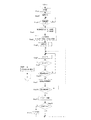
図8は、実施の形態1に係るレンジグリル調理の手動モード時におけるグリル調理時の報知、終了スキップ制御を示す制御フロー図である。
Next, the control flow at the time of shifting to grill heating (after “A” in FIG. 7) in step 10 and step 19 of FIG. 7 will be described with reference to FIG.
FIG. 8 is a control flowchart showing notification and end skip control during grill cooking in the manual mode of range grill cooking according to the first embodiment.

はじめにステップ20にてグリル加熱を開始すると、計時手段のカウンターt2を初期値であるゼロにセットする。なお、グリル加熱時間の最大値t2maxは、例えば1200秒に設定される。グリル加熱時間t2’は前述のように600秒とした例を説明する。   First, when grill heating is started in step 20, the counter t2 of the time measuring means is set to zero which is an initial value. Note that the maximum value t2max of the grill heating time is set to 1200 seconds, for example. An example in which the grill heating time t2 'is 600 seconds as described above will be described.

ステップ21で各センサーにて加熱状態の検出を開始する。ここでセンサーとは、加熱室2内の温度を検出する加熱室温度検出器であるサーミスタ42、調理物5の発する蒸気量を検出する蒸気検出器(本実施の形態においてはサーミスタ42)、調理物5の温度を非接触で検出する非接触温度検出器である赤外線センサー41などである。また、ステップ22にて計時手段のカウンターt2のカウントを開始する。
ステップ23にてカウンターt2の値が設定したグリル加熱時間t2’に達したか否かを判断する。
In step 21, detection of the heating state is started by each sensor. Here, the sensor means a thermistor 42 that is a heating chamber temperature detector that detects the temperature in the heating chamber 2, a steam detector that detects the amount of steam emitted from the food 5 (the thermistor 42 in the present embodiment), cooking An infrared sensor 41 is a non-contact temperature detector that detects the temperature of the object 5 in a non-contact manner. In step 22, the counting of the counter t2 of the time measuring means is started.
In step 23, it is determined whether or not the value of the counter t2 has reached the set grill heating time t2 ′.

カウンターt2の値が設定したグリル加熱時間t2’に達した場合にはステップ24に進み、グリル加熱を終了する。設定したグリル加熱時間t2’に達していない場合にはステップ25に進み、例えば上記の各センサーのうち加熱室2内の温度を検出する加熱室温度検出器(サーミスタ42)で検出した加熱室2内の温度が所定の閾値に達したかを判断する。   When the value of the counter t2 reaches the set grill heating time t2 ', the process proceeds to step 24, and the grill heating is terminated. If the set grill heating time t2 ′ has not been reached, the process proceeds to step 25, where the heating chamber 2 detected by a heating chamber temperature detector (thermistor 42) for detecting the temperature in the heating chamber 2 among the above-described sensors, for example. It is determined whether the internal temperature has reached a predetermined threshold.

加熱室2内の温度が所定の閾値に達した場合は、そのときの計時手段のカウンターt2の時間をt2aとして記憶部に記憶する。
ステップ26では記憶したt2aに所定の係数β(β>1)を乗算してグリル加熱を終了するのに適した予測終了時間t2a_endを演算する。
ここで、サーミスタ42で検出した加熱室2内の温度変化とグリル加熱を終了するのに適した予測終了時間t2a_endの関係について説明する。
When the temperature in the heating chamber 2 reaches a predetermined threshold value, the time of the counter t2 of the time measuring means at that time is stored in the storage unit as t2a.
In step 26, the stored t2a is multiplied by a predetermined coefficient β (β> 1) to calculate a predicted end time t2a_end suitable for ending the grill heating.
Here, the relationship between the temperature change in the heating chamber 2 detected by the thermistor 42 and the predicted end time t2a_end suitable for ending the grill heating will be described.

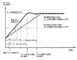
図9は、実施の形態1に係るグリル調理時の加熱室内の温度変化と予測終了時間t2a_endとの関係を示した図である。
図9において、横軸は計時手段のカウンターt2の経過時間を示し、縦軸に加熱室温度検出器(サーミスタ42)で検出した加熱室2内の温度を示している。
FIG. 9 is a diagram showing the relationship between the temperature change in the heating chamber during grill cooking and the predicted end time t2a_end according to the first embodiment.
In FIG. 9, the horizontal axis indicates the elapsed time of the counter t2 of the time measuring means, and the vertical axis indicates the temperature in the heating chamber 2 detected by the heating chamber temperature detector (thermistor 42).

グリル加熱が開始されると実線で示すように加熱室2内の温度が上昇をはじめる。加熱室2内の温度が例えば150℃(閾値)に到達したときの計時手段のカウンターt2の時間をt2aとして記憶する。記憶したt2aに所定の係数β(β>1)を乗算してグリル加熱を終了するのに適した予測終了時間t2a_endを演算する。この係数βは、グリル内の温度が例えば250℃に達するまでの時間を中間温度(150℃)に達した時点での温度勾配から予測し、グリル加熱の終了時刻を予め予測するための係数であり、調理物5に過度の焼き目や焦げ目が発生しない温度域で加熱を終了させる値に試験等から設定される。なお、図9の破線は、調理物5の熱容量が大きく、加熱室2内の温度上昇勾配が鈍い場合をしめしている。   When grill heating is started, the temperature in the heating chamber 2 starts to rise as shown by the solid line. The time of the counter t2 of the time measuring means when the temperature in the heating chamber 2 reaches, for example, 150 ° C. (threshold) is stored as t2a. The stored t2a is multiplied by a predetermined coefficient β (β> 1) to calculate a predicted end time t2a_end suitable for ending the grill heating. This coefficient β is a coefficient for predicting the time until the temperature in the grill reaches, for example, 250 ° C. from the temperature gradient at the time when the temperature reaches the intermediate temperature (150 ° C.), and predicting the end time of the grill heating in advance. Yes, it is set from a test or the like to a value at which heating is completed in a temperature range in which excessive baking or charring does not occur in the cooked product 5. In addition, the broken line of FIG. 9 has shown the case where the heat capacity of the cooking thing 5 is large and the temperature rise gradient in the heating chamber 2 is blunt.

つづいてステップ27では計時手段のカウンターt2のカウントを継続し、ステップ28においてt2の時間が予測終了時間t2a_endに達したか否かを判断する。
予測終了時間t2a_endに達していない場合にはステップ29に進み、t2がグリル加熱時間の最大値t2maxに達したかをさらに判断する。最大値t2maxに達した場合にはステップ30にてグリル加熱を終了する。
また、ステップ28にてt2の時間が予測終了時間t2a_endに達した場合にはステップ31に進み、使用者がグリル加熱を終了する終了スキップ操作を許可するとともに、報知手段52により報知を発報する。
Subsequently, at step 27, the counter t2 of the timing means is continuously counted, and at step 28, it is determined whether or not the time t2 has reached the predicted end time t2a_end.
If the predicted end time t2a_end has not been reached, the process proceeds to step 29 to further determine whether t2 has reached the maximum value t2max of the grill heating time. When the maximum value t2max is reached, the grill heating is terminated in step 30.
If the time t2 reaches the predicted end time t2a_end in step 28, the process proceeds to step 31, where the user permits the end skip operation to end the grill heating, and the notification means 52 issues a notification. .

この報知は、設定したグリル加熱時間t2’に計時手段のカウンターt2の値が達していない場合でも、調理物5の状態がグリル加熱を終了する条件を満たしたことを予測し、使用者に対してグリル加熱を終了する終了スキップ操作を促すためのものである。
報知手段52による報知は、表示部9への表示やパイロットサインでの表示、報知音や音声による報知など使用者にレンジ加熱を終了する条件が満たされたことを通知するものであれば様々な手段を採用することができる。
This notification predicts that the state of the cooked food 5 satisfies the condition for ending the grill heating even when the value of the counter t2 of the timing means has not reached at the set grill heating time t2 ′, and This is for prompting an end skip operation to end the grill heating.
The notification by the notification means 52 may be various as long as it notifies the user that the condition for ending the range heating is satisfied, such as display on the display unit 9, display with a pilot sign, notification by notification sound or voice. Means can be employed.

なお、報知を調理器の本体1から離れている使用者に確実に伝えるために少なくとも音による報知を行なうことが好ましい。更に、表示部9に例えば「グリル加熱を終了することが可能です。終了する場合は「とりけし」キーを押してください。」などの表示をし、その他の報知手段52を併用することが望ましい。また、終了スキップ操作をわかりやすくするために、この場合とりけし124に対応する発光部を点滅させることが望ましい。   In addition, it is preferable to perform at least sound notification in order to reliably transmit the notification to a user who is away from the main body 1 of the cooking device. In addition, for example, “Grill heating can be terminated. Press the“ Takeshiki ”key to terminate. It is desirable to use the other informing means 52 in combination. In order to make the end skip operation easier to understand, in this case, it is desirable to blink the light emitting unit corresponding to the cutout 124.

ここで、グリル加熱の終了を促す報知手段52による報知は、レンジ加熱の時と同様に、加熱前の初期状態で調理済みの調理物5を再加熱した場合を想定した第1報知と、加熱前の初期状態で未調理の調理物5を調理した場合を想定した第2報知を行なうように構成されている。この2回の報知はそれぞれの区別がつくように違う種類の報知(例えば、報知音の鳴動パターンが異なるなど)とすることが望ましい。
この場合、上記のようにステップ25にて加熱室2内の温度が、調理済みの調理物5を再加熱した場合のグリル加熱終了の判断に適した温度、例えば150℃(閾値)に到達したかを判断し、この閾値に温度が達したときのカウンターt2の時間をt2aとして記憶部に記憶する。そして、t2aに所定の係数β(β>1)を乗算してグリル加熱を終了するのに適した予測終了時間t2a_endを算出し、この予測終了時間t2a_endが経過したときに第1報知を発報する。
Here, the notification by the notification means 52 that prompts the end of grill heating is the same as in the case of the range heating, the first notification assuming the case where the cooked food 5 is reheated in the initial state before heating, and heating. It is comprised so that the 2nd alerting | reporting which assumes the case where the uncooked food 5 was cooked in the previous initial state may be performed. The two notifications are preferably different types of notifications (for example, different sounding patterns of notification sounds) so that the respective notifications can be distinguished.
In this case, as described above, the temperature in the heating chamber 2 has reached a temperature suitable for determination of the end of grill heating when the cooked food 5 is reheated, for example, 150 ° C. (threshold), as described above. The time of the counter t2 when the temperature reaches this threshold is stored in the storage unit as t2a. Then, t2a is multiplied by a predetermined coefficient β (β> 1) to calculate a predicted end time t2a_end suitable for ending the grill heating, and the first notification is issued when the predicted end time t2a_end has elapsed. To do.

また、加熱前の初期状態で未調理の調理物5を調理していることを想定した第2報知は、加熱室2内の温度が未調理の調理物5を調理した際のグリル加熱終了の判断に適した温度、例えば200℃(閾値)に到達したかを判断し、この閾値に温度が達したときのカウンターt2の時間をt2bとして記憶部に記憶する。そして、t2bに所定の係数γ(γ>1)を乗算してグリル加熱を終了するのに適した予測終了時間t2b_endを算出し、この予測終了時間t2b_endが経過したときに第2報知を発報する。
このように、加熱前の初期状態で調理済みの調理物5を再加熱していることを想定した第1報知と、加熱前の初期状態で未調理の調理物5を調理していることを想定した第2報知とに分けて報知を2回行うことで、加熱前の初期状態の調理形態に対応した終了スキップ操作が可能となる。
Moreover, the 2nd alert | report which assumed that the uncooked food 5 is cooking in the initial state before a heating is the completion | finish of grill heating when the temperature in the heating chamber 2 cooked the uncooked food 5 It is determined whether a temperature suitable for determination, for example, 200 ° C. (threshold) has been reached, and the time of the counter t2 when the temperature has reached this threshold is stored in the storage unit as t2b. Then, t2b is multiplied by a predetermined coefficient γ (γ> 1) to calculate a predicted end time t2b_end suitable for ending the grill heating, and a second notification is issued when the predicted end time t2b_end has elapsed. To do.
As described above, the first notification assuming that the cooked food 5 is reheated in the initial state before heating, and that the uncooked food 5 is cooked in the initial state before heating. By performing notification twice for the assumed second notification, an end skip operation corresponding to the cooking state in the initial state before heating can be performed.

次にステップ32にて使用者による終了スキップ操作(例えば取消しキー124の操作)があったか否かを判断する。終了スキップ操作があった場合には、ステップ33に進み終了スキップ操作によりグリル加熱が短縮された時間(設定されたグリル加熱時間t2’−予測終了時間t2endの値)から削減された電力量を演算して記憶し表示部9に表示するとともに、ステップ37にて報知手段52をオフとし、ステップ38にてグリル加熱を終了する。終了スキップ操作がなかった場合にはステップ34に進み、計時手段のカウンターt2のカウントを継続する。   Next, in step 32, it is determined whether or not an end skip operation (for example, operation of the cancel key 124) has been performed by the user. If there is an end skip operation, the process proceeds to step 33 to calculate the amount of power reduced from the time when grill heating is shortened by the end skip operation (the set grill heating time t2′−predicted end time t2end value). The information is stored and displayed on the display unit 9, and the notification means 52 is turned off in step 37, and the grill heating is terminated in step 38. If there is no end skip operation, the process proceeds to step 34, and the counting of the counter t2 of the time measuring means is continued.

ステップ35にてカウンターt2の値が設定したグリル加熱時間t2’に達したか否かを判断する。
カウンターt2の値が設定したグリル加熱時間t2’に達していない場合はステップ36に進み、グリル加熱時間の最大値t2maxに達したか否かをさらに判断する。ステップ35でカウンターt2の値が設定したグリル加熱時間t2’に達した場合、及び、ステップ36にてカウンターt2の値がグリル加熱時間の最大値t2maxに達した場合には、ステップ37にて報知手段52をオフとし、ステップ38にてグリル加熱を終了する。
In step 35, it is determined whether or not the value of the counter t2 has reached the set grill heating time t2 ′.
When the value of the counter t2 has not reached the set grill heating time t2 ′, the process proceeds to step 36, and it is further determined whether or not the maximum value t2max of the grill heating time has been reached. When the value of the counter t2 reaches the grill heating time t2 ′ set at step 35, and when the value of the counter t2 reaches the maximum value of the grill heating time t2max at step 36, a notification is made at step 37. The means 52 is turned off and the grill heating is terminated in step 38.

実施の形態1に係る加熱調理器では、レンジグリル調理を行う際に手動モードで複数の加熱手段の各加熱時間を使用者が設定した際にも、調理物5に対応して最適に各加熱手段の切り替え時期を報知してくれるとともに、加熱の終了時期も報知してくれるため、使用者が各加熱時間を過度に長時間設定しても複数の加熱手段で適切な連続運転を実行することができる。   In the heating cooker according to the first embodiment, when the user sets each heating time of the plurality of heating means in the manual mode when cooking the range grill, each heating is optimally performed corresponding to the food 5. In addition to notifying the switching timing of the means and also the end time of heating, even if the user sets each heating time excessively long, appropriate continuous operation is performed with multiple heating means Can do.

また、これらの報知は自動調理における移行タイミングで行なうようにした為、使用者が手動モードで加熱調理したレシピが、自動モードで過不足なく調理できるか否かを判断することができる。すなわち、報知に基づいて使用者がスキップ操作を実行して調理を行なった結果、良好な仕上がり状態となっていれば、次回からは自動モードで加熱調理できるとの判断をすることができるので、使い勝手を向上させることができる。   Moreover, since these notifications are made at the transition timing in automatic cooking, it is possible to determine whether or not the recipe cooked by the user in the manual mode can be cooked without excess or deficiency in the automatic mode. That is, as a result of cooking by performing a skip operation by the user based on the notification, if it is in a good finished state, it can be determined that cooking can be performed in automatic mode from the next time, Usability can be improved.

それから、使用者が各加熱手段の切り替え時期や加熱の終了時期を報知により判断してスキップさせ加熱時間を短縮するため、余分な加熱運転を回避して消費電力量を削減することが可能になる。なお、削減した消費電力量は、不揮発性メモリ45aに記憶させておき、削減した消費電力量を表示するモードを設け、スキップ操作により削減した電力量の累計を表示させるなどしてもよい。   Then, since the user judges by skipping the switching timing of each heating means and the end timing of heating and skips the heating time, it becomes possible to avoid excessive heating operation and reduce power consumption. . Note that the reduced power consumption amount may be stored in the nonvolatile memory 45a, and a mode for displaying the reduced power consumption amount may be provided to display a cumulative amount of power reduced by the skip operation.

実施の形態2.
実施の形態2に係る加熱調理器は、実施の形態1に係る加熱調理器のレンジグリル調理の手動モードにおける制御と基本的に同じであるが、手動で設定したレンジ加熱時間t1’と、グリル加熱時間t2’とを加熱運転の途中で変更可能な点で異なる。
Embodiment 2. FIG.
The cooker according to the second embodiment is basically the same as the control in the manual mode of the range grill cooking of the cooker according to the first embodiment, but the range heating time t1 ′ set manually and the grill The difference is that the heating time t2 'can be changed during the heating operation.

<レンジグリル調理の手動モード時における設定時間変更制御>
図10は、実施の形態2に係るレンジグリル調理の手動モード時における設定時間変更制御を示す制御フロー図である。
この制御フローにおいて、ステップ1からステップ6までは実施の形態1と同じである。
<Setting time change control in manual mode of range grill cooking>
FIG. 10 is a control flowchart showing set time change control in the manual mode of range grill cooking according to the second embodiment.
In this control flow, steps 1 to 6 are the same as those in the first embodiment.

すなわち、ステップ1にてドア4が開くと、ステップ2にて電源をオンする。次にステップ3にて手動モードが選択されたか否かを判断する。手動モードの場合にはステップ4に進み、レンジ加熱時間t1’とグリル加熱時間t2’の両方が設定された時点でステップ5に進む。
ここで、ステップ4においてレンジ加熱時間t1’を180秒、グリル加熱時間t2’を600秒とした例を説明する。
That is, when the door 4 is opened in step 1, the power is turned on in step 2. Next, in step 3, it is determined whether or not the manual mode is selected. In the case of the manual mode, the process proceeds to Step 4 and proceeds to Step 5 when both the range heating time t1 ′ and the grill heating time t2 ′ are set.
Here, an example in which the range heating time t1 ′ is 180 seconds and the grill heating time t2 ′ is 600 seconds in step 4 will be described.

ステップ5にてレンジの出力を600Wに固定し、計時手段のカウンターt1を初期値であるゼロにセットする。なお、レンジ加熱時間の最大値t1maxは、例えば300秒に設定される。
ステップ6で加熱がスタートすると、ステップ7にて計時手段のカウンターt1のカウントを開始する。
ステップ8にてカウンターt1の値が設定したレンジ加熱時間t1’に達したか否かを判断する。
In step 5, the output of the range is fixed to 600 W, and the counter t1 of the time measuring means is set to the initial value zero. In addition, the maximum value t1max of the range heating time is set to 300 seconds, for example.
When heating starts in step 6, counting of the counter t1 of the time measuring means is started in step 7.
In step 8, it is determined whether or not the value of the counter t1 has reached the set range heating time t1 ′.

カウンターt1の値が設定したレンジ加熱時間t1’に達した場合にはステップ9に進み、グリル加熱に移行する。設定したレンジ加熱時間t1’に達していない場合にはステップ10に進み、設定したレンジ加熱時間t1’が時間変更されたか否かを判断する。   When the value of the counter t1 reaches the set range heating time t1 ', the process proceeds to step 9 to shift to grill heating. If the set range heating time t1 'has not been reached, the process proceeds to step 10 to determine whether or not the set range heating time t1' has been changed.

時間変更があった場合はステップ11にて増加もしくは減少した設定時間を記憶する。 ここで、設定したレンジ加熱時間t1’を変更する際には例えば操作部8のプラスキー111やマイナスキー112を操作することで表示部9に表示されたレンジ加熱時間t1’を増減することができる。操作は、例えばプラスキー1回の押下で+10秒、長押しで連続的に時間が増加するなどの変更が採用可能である。また、時間の変更中は表示部9に表示されたレンジ加熱時間t1’を点滅させる。   If there is a time change, the set time increased or decreased in step 11 is stored. Here, when changing the set range heating time t1 ′, the range heating time t1 ′ displayed on the display unit 9 can be increased or decreased by operating the plus key 111 or the minus key 112 of the operation unit 8, for example. it can. For the operation, for example, it is possible to adopt a change such as +10 seconds when the plus key is pressed once, and time is continuously increased by long pressing. Further, during the time change, the range heating time t1 'displayed on the display unit 9 is blinked.

次に、ステップ12にて設定時間変更の確定操作があったか否かを判断する。確定操作は、例えばスタートキー121を押下して決定する。または、最後にプラスキー111やマイナスキー112を操作してから一定時間経過した時点で確定してもよい。
確定操作が行われると表示部9に表示されたレンジ加熱時間t1’の点滅が点灯へと変更されステップ13にて例えばレンジ加熱時間t1’から30秒が減算される。
Next, in step 12, it is determined whether or not a setting time change confirmation operation has been performed. The confirmation operation is determined by pressing the start key 121, for example. Alternatively, it may be determined when a certain time has elapsed since the last time the plus key 111 or the minus key 112 was operated.
When the confirmation operation is performed, the blinking of the range heating time t1 ′ displayed on the display unit 9 is changed to lighting, and in step 13, for example, 30 seconds is subtracted from the range heating time t1 ′.

ステップ14にて時間変更されたレンジ加熱時間t1’がレンジ加熱時間の最大値t1max以上か否かを判断する。最大値t1max以上の場合にはステップ15にて時間変更されたレンジ加熱時間t1’はレンジ加熱時間の最大値t1maxとされる。最大値t1max未満の場合には、ステップ7に戻り計時手段のカウンターt1を継続してカウントする。   It is determined whether or not the range heating time t1 'whose time has been changed in step 14 is equal to or greater than the maximum value t1max of the range heating time. If the maximum value t1max is greater than or equal to the maximum value t1max, the range heating time t1 'changed in step 15 is set to the maximum value t1max of the range heating time. If it is less than the maximum value t1max, the process returns to step 7 and the counter t1 of the time measuring means is continuously counted.

なお、実施の形態2に係る設定時間変更制御は、実施の形態1に係るレンジグリル調理の手動モード時における報知、スキップ制御と組み合わせて実行することが可能である。
具体的には、図7の制御フローにおけるステップ9の後に実施の形態2に係る図10の制御フローのステップ10以下を割り込ませてレンジ加熱時間t1’を変更可能とすることができる。
The set time change control according to the second embodiment can be executed in combination with notification and skip control in the manual mode of the range grill cooking according to the first embodiment.
Specifically, after step 9 in the control flow of FIG. 7, the range heating time t1 ′ can be changed by interrupting step 10 and subsequent steps of the control flow of FIG. 10 according to the second embodiment.

また、実施の形態2に係る設定時間変更制御は、実施の形態1に係るグリル加熱時間t2’の変更にも採用することができる。
具体的には図8の制御フローにおけるステップ23の後に実施の形態2に係る図9の制御フローのステップ10以下を割り込ませてグリル加熱時間t2’を変更可能とすることができる。
Further, the set time change control according to the second embodiment can also be employed for changing the grill heating time t2 ′ according to the first embodiment.
Specifically, the grill heating time t2 ′ can be changed by interrupting step 10 and subsequent steps of the control flow of FIG. 9 according to the second embodiment after step 23 of the control flow of FIG.

実施の形態2に係る加熱調理器によれば、実施の形態1に係る加熱調理器のレンジグリル調理時の報知、スキップ制御に加え、手動で設定したレンジ加熱時間t1’と、グリル加熱時間t2’とを加熱運転の途中で変更可能としたことで、予め設定した加熱時間が短かった場合にも対処することができ、使用者の使い勝手をさらに向上させることができる。   According to the heating cooker according to the second embodiment, in addition to the notification and skip control at the time of cooking the range grill of the heating cooker according to the first embodiment, the manually set range heating time t1 ′ and the grill heating time t2 Since 'can be changed during the heating operation, it is possible to cope with a case where the preset heating time is short, and the usability of the user can be further improved.

1 本体、2 加熱室、3 窓、4 ドア、5 調理物、6 調理プレート、7 ハンドル、8 操作部、8a 下辺、8b 左辺、9 表示部、9a レンジ加熱時間表示エリア、9b ヒーター加熱時間表示エリア、9c 仕切り線、18 フラットヒーター、19 断熱材、20 板金、21 アンテナ、22 シーズヒーター、23 セラミックプレート、24 下部加熱室、25 アンテナモーター、26 導波管、28 チョーク、29 開口パネル、30 背面加熱室、31 背面ガラス管ヒーター、32 反射部、33 背面開口部、34 ターボファン、35 循環室、36 ファンモーター、37 吸気口、38 マグネトロン、39 インバーター基板、41 赤外線センサー、42 サーミスタ(加熱室温度検出器)、43 マグネトロン駆動手段、44 制御部、45 マイコン、45a 不揮発性メモリ、46 キー入力判定手段、47 表示駆動手段、48 LED駆動手段、49 ヒーター駆動手段、50 モーター駆動手段、51 ファンモーター駆動手段、52 報知手段、53 ドア開閉検出手段、101 第1の操作入力領域、102 レンジキー、103 レンジグリルキー、104 グリルキー、105 オーブンキー、106 発光部、107 発光部、108 発光部、109 発光部、110 第2の操作入力領域、111 プラスキー、112 マイナスキー、113 発光部、114 発光部、115 第1の加熱時間設定キー、116 第2の加熱時間設定キー、117 第3の加熱時間設定キー、118 発光部、119 発光部、120 発光部、121 スタートキー、122 発光部、123 第3の操作入力領域、124 取消しキー。   DESCRIPTION OF SYMBOLS 1 Main body, 2 Heating chamber, 3 Window, 4 Door, 5 Cooked food, 6 Cooking plate, 7 Handle, 8 Operation part, 8a Lower side, 8b Left side, 9 Display part, 9a Range heating time display area, 9b Heater heating time display Area, 9c Partition line, 18 Flat heater, 19 Thermal insulation, 20 Sheet metal, 21 Antenna, 22 Seed heater, 23 Ceramic plate, 24 Lower heating chamber, 25 Antenna motor, 26 Waveguide, 28 Choke, 29 Open panel, 30 Rear heating chamber, 31 Rear glass tube heater, 32 Reflector, 33 Rear opening, 34 Turbo fan, 35 Circulation chamber, 36 Fan motor, 37 Air inlet, 38 Magnetron, 39 Inverter board, 41 Infrared sensor, 42 Thermistor (heating) Room temperature detector), 43 magnetron drive Means, 44 control unit, 45 microcomputer, 45a nonvolatile memory, 46 key input determination means, 47 display drive means, 48 LED drive means, 49 heater drive means, 50 motor drive means, 51 fan motor drive means, 52 notification means, 53 door opening / closing detection means, 101 first operation input area, 102 range key, 103 range grill key, 104 grill key, 105 oven key, 106 light emitting part, 107 light emitting part, 108 light emitting part, 109 light emitting part, 110 second Operation input area, 111 plus key, 112 minus key, 113 light emitting unit, 114 light emitting unit, 115 first heating time setting key, 116 second heating time setting key, 117 third heating time setting key, 118 light emitting unit 119 Light-emitting unit, 120 Light-emitting unit, 121 Start key -, 122 Light emitting unit, 123 Third operation input area, 124 Cancel key.

Claims (13)

加熱特性の異なる複数の加熱手段と前記加熱手段の運転を制御する制御手段とを有し、少なくとも前記加熱手段のうちの特定の加熱手段の運転に続けて前記特定の加熱手段以外の他の加熱手段を連続して運転する連続運転モードを備えた加熱調理器であって、
前記制御手段は、前記連続運転モードの時に予め入力された前記加熱手段の各運転時間となるよう各加熱手段の運転を行い、前記特定の加熱手段の運転中に前記他の加熱手段の運転に移行する移行スキップ操作手段を備えたことを特徴とする加熱調理器。
A plurality of heating means having different heating characteristics and a control means for controlling operation of the heating means, and at least heating other than the specific heating means following the operation of the specific heating means of the heating means A cooking device having a continuous operation mode for continuously operating the means,
The control means operates each heating means so as to have each operation time of the heating means input in advance in the continuous operation mode, and operates the other heating means during the operation of the specific heating means. A cooking device comprising a transition skip operation means for transition.
前記制御手段は、前記移行スキップ操作手段の操作があった際には、前記特定の加熱手段の運転を中断して前記他の加熱手段の運転に移行するように構成されたことを特徴とする請求項1に記載の加熱調理器。   The control unit is configured to interrupt the operation of the specific heating unit and shift to the operation of the other heating unit when the transition skip operation unit is operated. The cooking device according to claim 1. 前記制御手段は、前記移行スキップ操作手段の操作を促す報知を調理物の加熱前の初期状態に対応して複数回の報知をするように構成されたことを特徴とする請求項1または2に記載の加熱調理器。   3. The control unit according to claim 1, wherein the control unit is configured to perform a plurality of notifications in response to an initial state before heating of the food to be urged to operate the transition skip operation unit. The cooking device described. 前記制御手段は、加熱室内の温度を検出する加熱室温度検出器、調理物の発する蒸気量を検出する蒸気検出器、調理物の温度を非接触で検出する非接触温度検出器のうちのいずれか1つの検出値が既定値以上になったことに基づいて前記移行スキップ操作手段の操作を許可するように構成されたことを特徴とする請求項1〜3のいずれか1項に記載の加熱調理器。   The control means is any one of a heating chamber temperature detector that detects the temperature in the heating chamber, a steam detector that detects the amount of steam generated by the food, and a non-contact temperature detector that detects the temperature of the food in a non-contact manner. The heating according to any one of claims 1 to 3, wherein the operation of the transition skip operation means is permitted based on the fact that one detected value is equal to or greater than a predetermined value. Cooking device. 前記制御手段は、前記移行スキップ操作手段の操作があった際に、前記予め入力された加熱手段の各運転時間から短縮された時間に基づいて削減された電力量を表示手段に表示することを特徴とする請求項1〜4のいずれか1項に記載の加熱調理器。   The control means displays on the display means the amount of power reduced based on the time shortened from each operation time of the heating means input in advance when the transition skip operation means is operated. The cooking device according to any one of claims 1 to 4, characterized in that: 前記制御手段は、前記他の加熱手段の運転中に運転を終了する終了スキップ操作手段を備え、前記終了スキップ操作手段の操作があった際には、前記他の加熱手段の運転を中断して加熱運転を終了するように構成されたことを特徴とする請求項1〜5のいずれか1項に記載の加熱調理器。   The control means includes an end skip operation means for ending the operation during the operation of the other heating means. When the end skip operation means is operated, the operation of the other heating means is interrupted. The cooking device according to any one of claims 1 to 5, wherein the cooking device is configured to end the heating operation. 前記制御手段は、前記終了スキップ操作手段の操作を促す報知を調理物の加熱前の初期状態に対応して複数回の報知をするように構成されたことを特徴とする請求項6に記載の加熱調理器。   The said control means is comprised so that the alerting | reporting which prompts operation of the said completion | finish skip operation means may be alert | reported in multiple times corresponding to the initial state before the heating of a foodstuff. Cooking cooker. 前記制御手段は、加熱室内の温度を検出する加熱室温度検出器の検出値が既定値以上になったことに基づいて前記終了スキップ操作手段の操作を許可するように構成されたことを特徴とする請求項6または7に記載の加熱調理器。   The control means is configured to permit the operation of the end skip operation means based on a detection value of a heating chamber temperature detector for detecting a temperature in the heating chamber being equal to or higher than a predetermined value. The cooking device according to claim 6 or 7. 前記制御手段は、前記終了スキップ操作手段の操作があった際に、前記予め入力された加熱手段の各運転時間から短縮された時間に基づいて削減された電力量を表示手段に表示することを特徴とする請求項6〜8のいずれか1項に記載の加熱調理器。   The control means displays on the display means the amount of power reduced based on the time shortened from each operation time of the heating means inputted in advance when the end skip operation means is operated. The cooking device according to any one of claims 6 to 8, wherein the cooking device is a cooking device. 前記複数回の報知は、それぞれ異なる種類の報知内容であることを特徴とする請求項3または7に記載された加熱調理器。   The cooking device according to claim 3 or 7, wherein the plurality of notifications are different types of notification contents. 前記報知は、少なくとも表示手段に文字情報を表示するものであることを特徴とする請求項3〜10のいずれか1項に記載の加熱調理器。   The cooking device according to any one of claims 3 to 10, wherein the notification is for displaying character information on at least display means. 前記制御手段は、前記加熱手段の運転中に前記予め入力された加熱手段の各運転時間を変更する時間変更操作があった際に、前記予め入力された加熱手段の各運転時間を変更するように構成されたことを特徴とする請求項1〜11のいずれか1項に記載の加熱調理器。   The control means changes each operation time of the heating means inputted in advance when there is a time change operation for changing each operation time of the heating means inputted in advance during operation of the heating means. The cooking device according to any one of claims 1 to 11, wherein the cooking device is configured as described above. 前記特定の加熱手段はマイクロ波を利用した加熱手段であり、前記他の加熱手段はヒーターを利用した加熱手段であることを特徴とする請求項1〜12のいずれか1項に記載の加熱調理器。   The cooking according to any one of claims 1 to 12, wherein the specific heating means is a heating means using microwaves, and the other heating means is a heating means using a heater. vessel.
JP2013255028A 2013-12-10 2013-12-10 Cooker Expired - Fee Related JP6165041B2 (en)

Priority Applications (1)

Application Number Priority Date Filing Date Title
JP2013255028A JP6165041B2 (en) 2013-12-10 2013-12-10 Cooker

Applications Claiming Priority (1)

Application Number Priority Date Filing Date Title
JP2013255028A JP6165041B2 (en) 2013-12-10 2013-12-10 Cooker

Publications (2)

Publication Number Publication Date
JP2015114011A true JP2015114011A (en) 2015-06-22
JP6165041B2 JP6165041B2 (en) 2017-07-19

Family

ID=53527986

Family Applications (1)

Application Number Title Priority Date Filing Date
JP2013255028A Expired - Fee Related JP6165041B2 (en) 2013-12-10 2013-12-10 Cooker

Country Status (1)

Country Link
JP (1) JP6165041B2 (en)

Cited By (4)

* Cited by examiner, † Cited by third party
Publication number Priority date Publication date Assignee Title
JP2017223383A (en) * 2016-06-13 2017-12-21 シャープ株式会社 Cooking device
JP2021196100A (en) * 2020-06-12 2021-12-27 日立グローバルライフソリューションズ株式会社 Heating cooker
JP2022183598A (en) * 2021-05-31 2022-12-13 日立グローバルライフソリューションズ株式会社 heating cooker
JP2023037928A (en) * 2021-09-06 2023-03-16 アイリスオーヤマ株式会社 Cooker

Citations (4)

* Cited by examiner, † Cited by third party
Publication number Priority date Publication date Assignee Title
JPS58167802U (en) * 1982-04-30 1983-11-09 三洋電機株式会社 cooking equipment
JPS60186623A (en) * 1984-03-05 1985-09-24 Sanyo Electric Co Ltd Electronic control type cooking apparatus
JP2004218922A (en) * 2003-01-14 2004-08-05 Sanyo Electric Co Ltd Heating cooking apparatus
JP2013167422A (en) * 2012-02-16 2013-08-29 Sharp Corp Cooking heater and electric equipment

Patent Citations (4)

* Cited by examiner, † Cited by third party
Publication number Priority date Publication date Assignee Title
JPS58167802U (en) * 1982-04-30 1983-11-09 三洋電機株式会社 cooking equipment
JPS60186623A (en) * 1984-03-05 1985-09-24 Sanyo Electric Co Ltd Electronic control type cooking apparatus
JP2004218922A (en) * 2003-01-14 2004-08-05 Sanyo Electric Co Ltd Heating cooking apparatus
JP2013167422A (en) * 2012-02-16 2013-08-29 Sharp Corp Cooking heater and electric equipment

Cited By (6)

* Cited by examiner, † Cited by third party
Publication number Priority date Publication date Assignee Title
JP2017223383A (en) * 2016-06-13 2017-12-21 シャープ株式会社 Cooking device
JP2021196100A (en) * 2020-06-12 2021-12-27 日立グローバルライフソリューションズ株式会社 Heating cooker
JP2022183598A (en) * 2021-05-31 2022-12-13 日立グローバルライフソリューションズ株式会社 heating cooker
JP7659442B2 (en) 2021-05-31 2025-04-09 日立グローバルライフソリューションズ株式会社 Cooking equipment
JP2023037928A (en) * 2021-09-06 2023-03-16 アイリスオーヤマ株式会社 Cooker
JP7563754B2 (en) 2021-09-06 2024-10-08 アイリスオーヤマ株式会社 Cooking equipment

Also Published As

Publication number Publication date
JP6165041B2 (en) 2017-07-19

Similar Documents

Publication Publication Date Title
JP5955229B2 (en) Cooker
KR20100010248A (en) Cooker and method for controlling temperature
JP5033733B2 (en) Induction heating cooker
JP6165041B2 (en) Cooker
JP7435708B2 (en) heating cooker
US7005614B2 (en) Cooking apparatus equipped with heaters and method of controlling the same
JP5795931B2 (en) Induction heating cooker
JP2009180392A (en) Microwave oven
JP2013053795A (en) Heating cooker
JP4998177B2 (en) Cooking equipment
JP7314875B2 (en) electrical equipment, cooker
JP2021034234A (en) Induction heating cooker and heating method thereof
JP2007051806A (en) Cooker
JP2014219155A (en) Heating cooker
JP2011228030A (en) Induction heating cooker
WO2012029309A1 (en) Radio frequency heating apparatus
JP4969350B2 (en) Induction heating cooker
JP6364622B2 (en) Induction heating cooker
JP2003217813A (en) Electromagnetic cooker
JP2014085056A (en) Heating cooker
JP2012154539A (en) Heat cooking device
JP5787602B2 (en) Operation unit and cooking device provided with the operation unit
JP2010244997A (en) Induction heating cooker
JP2023113204A (en) heating cooker
JP2004039375A (en) Cooker

Legal Events

Date Code Title Description
A621 Written request for application examination

Free format text: JAPANESE INTERMEDIATE CODE: A621

Effective date: 20160624

A977 Report on retrieval

Free format text: JAPANESE INTERMEDIATE CODE: A971007

Effective date: 20170313

A131 Notification of reasons for refusal

Free format text: JAPANESE INTERMEDIATE CODE: A131

Effective date: 20170321

A521 Request for written amendment filed

Free format text: JAPANESE INTERMEDIATE CODE: A523

Effective date: 20170509

TRDD Decision of grant or rejection written
A01 Written decision to grant a patent or to grant a registration (utility model)

Free format text: JAPANESE INTERMEDIATE CODE: A01

Effective date: 20170523

A61 First payment of annual fees (during grant procedure)

Free format text: JAPANESE INTERMEDIATE CODE: A61

Effective date: 20170620

R150 Certificate of patent or registration of utility model

Ref document number: 6165041

Country of ref document: JP

Free format text: JAPANESE INTERMEDIATE CODE: R150

R250 Receipt of annual fees

Free format text: JAPANESE INTERMEDIATE CODE: R250

R250 Receipt of annual fees

Free format text: JAPANESE INTERMEDIATE CODE: R250

R250 Receipt of annual fees

Free format text: JAPANESE INTERMEDIATE CODE: R250

R250 Receipt of annual fees

Free format text: JAPANESE INTERMEDIATE CODE: R250

LAPS Cancellation because of no payment of annual fees