JP2015112129A - Game machine - Google Patents
Game machine Download PDFInfo
- Publication number
- JP2015112129A JP2015112129A JP2013253851A JP2013253851A JP2015112129A JP 2015112129 A JP2015112129 A JP 2015112129A JP 2013253851 A JP2013253851 A JP 2013253851A JP 2013253851 A JP2013253851 A JP 2013253851A JP 2015112129 A JP2015112129 A JP 2015112129A
- Authority
- JP
- Japan
- Prior art keywords
- big hit
- effect
- display
- symbol
- special symbol
- Prior art date
- Legal status (The legal status is an assumption and is not a legal conclusion. Google has not performed a legal analysis and makes no representation as to the accuracy of the status listed.)
- Pending
Links
Images


Landscapes
- Pinball Game Machines (AREA)
- Display Devices Of Pinball Game Machines (AREA)
Abstract
Description
本発明は、遊技媒体を用いて遊技を行うことが可能なパチンコ遊技機等の遊技機に関する。 The present invention relates to a gaming machine such as a pachinko gaming machine capable of playing a game using a game medium.
遊技機として、遊技媒体である遊技球を発射装置によって遊技領域に発射し、遊技領域に設けられている入賞口などの入賞領域に遊技球が入賞すると、所定の入賞価値を遊技者に与えるように構成されたものがある。さらに、識別情報を可変表示(「変動」ともいう。)可能な可変表示手段が設けられ、可変表示手段において識別情報の可変表示の表示結果が特定表示結果となった場合に、所定の遊技価値を遊技者に与えるように構成されたものがある。 As a gaming machine, a game ball, which is a game medium, is launched into a game area by a launching device, and when a game ball wins a prize area such as a prize opening provided in the game area, a predetermined prize value is given to the player There is something that was configured. Furthermore, variable display means capable of variably displaying the identification information (also referred to as “fluctuation”) is provided, and when the display result of the variable display of the identification information in the variable display means becomes a specific display result, a predetermined game value Are configured to give the player.
なお、入賞価値とは、入賞領域への遊技球の入賞に応じて賞球を払い出したり得点や景品を付与したりすることである。また、遊技価値とは、特定表示結果となった場合に遊技機の遊技領域に設けられた可変入賞球装置の状態が打球が入賞しやすい遊技者にとって有利な状態になることや、遊技者にとって有利な状態になるための権利を発生させたりすることや、賞球払出の条件が成立しやすくなる状態になることである。 The winning value means that a winning ball is paid out or a score or a prize is given in accordance with the winning of a game ball in the winning area. In addition, the game value means that when a specific display result is obtained, the state of the variable winning ball apparatus provided in the gaming area of the gaming machine becomes an advantageous state for a player who is easy to win, and for the player. For example, a right to be advantageous can be generated, and a condition for paying out a winning ball can be easily established.
パチンコ遊技機では、始動入賞口に遊技球が入賞したことにもとづいて可変表示手段において開始される特別図柄(識別情報)の可変表示の表示結果として、あらかじめ定められた特定の表示態様が導出表示された場合に、「大当り(特定遊技状態)」が発生する。なお、導出表示とは、図柄を停止表示させることである。大当りが発生すると、例えば、大入賞口が所定回数開放して打球が入賞しやすい大当り遊技状態に移行する。そして、各開放期間において、所定個(例えば10個)の大入賞口への入賞があると大入賞口は閉成する。そして、大入賞口の開放回数は、所定回数(例えば15ラウンド)に固定されている。なお、各開放について開放時間(例えば29秒)が決められ、入賞数が所定個に達しなくても開放時間が経過すると大入賞口は閉成する。以下、各々の大入賞口の開放期間をラウンドということがある。 In a pachinko machine, a specific display mode determined in advance is derived and displayed as a display result of variable display of a special symbol (identification information) that is started by variable display means based on the winning of a game ball at the start winning opening. When it is made, “big hit (specific game state)” occurs. The derived display is to stop and display the symbol. When the big hit occurs, for example, the big winning opening is opened a predetermined number of times, and the game shifts to a big hit gaming state where the hit ball is easy to win. And in each open period, if there is a prize for a predetermined number (for example, 10) of the big prize opening, the big prize opening is closed. And the number of times the special winning opening is opened is fixed to a predetermined number (for example, 15 rounds). An opening time (for example, 29 seconds) is determined for each opening, and even if the number of winnings does not reach a predetermined number, the big winning opening is closed when the opening time elapses. Hereinafter, the opening period of each special winning opening may be referred to as a round.
そのような遊技機において、所定条件が成立した後に、特定領域に向けた遊技媒体の発射操作を促す発射促進報知を行うように構成されたものがある。例えば、特許文献1には、所定条件が成立(大当り抽選に当選)した後に、レールユニットの出口から遊技媒体(遊技球)の通過が検出されなければ、「球を正常に発射してね!」などの態様で発射促進報知を行うことが記載されている。
Some of such gaming machines are configured to perform a launch promotion notification that prompts a launch operation of a game medium toward a specific area after a predetermined condition is established. For example, in
また、例えば、特許文献2には、遊技媒体(遊技球)を右遊技領域に発射することを促す複数種類の右打ち指示報知を実行することが記載されている。また、特許文献2には、いずれの種類の右打ち指示報知が実行されたかに応じて、16ラウンドまたは8ラウンドのいずれの大当り状態に制御されるかの割合が異なることが記載されている。
Further, for example,
特許文献1に記載された遊技機では、発射促進報知を実行することによって、所定条件が成立した後に特定領域を遊技媒体が通過したことにもとづいて可変入賞装置を作動させる(大当り遊技状態に移行させる)ように構成した場合の遊技者の不利益を防止している。しかし、発射促進報知の報知態様が一様の態様のものしかなく、発射促進報知を実行する場合の遊技の興趣を十分に高めることはできない。また、特許文献2には、発射促進報知に関連した報知として複数種類の右打ち指示報知を実行することが記載されているが、所定条件が成立した後に特定領域を遊技媒体が通過したことにもとづいて可変入賞装置を作動させるように構成したものではなく、特許文献2に記載された構成を用いたとしても発射促進報知を実行する場合の遊技の興趣を十分に高めることはできない。
In the gaming machine described in
そこで、本発明は、発射促進報知を実行する場合の遊技の興趣を向上させることができる遊技機を提供することを目的とする。 Then, an object of this invention is to provide the gaming machine which can improve the interest of the game in the case of performing launch promotion notification.
(手段1)本発明による遊技機は、遊技媒体(例えば、遊技球)を用いて遊技を行うことが可能な遊技機であって、所定条件が成立(例えば、大当り図柄を停止表示)した後に、特定領域(例えば、特定ゲート200)を遊技媒体が通過したことにもとづいて、可変入賞装置(例えば、特別可変入賞球装置20(大入賞口))を作動させる可変入賞装置制御手段(例えば、遊技制御用マイクロコンピュータ560におけるステップS133〜S137,S1401〜S1407,S1451〜S1466を実行する部分)と、所定条件が成立した後に、特定領域に向けた遊技媒体の発射操作を促す発射促進報知(例えば、図43(6)、図44(6)および図45(6)に示す右打ち演出)を実行する発射促進報知実行手段(例えば、演出制御用マイクロコンピュータ100におけるステップS865〜S871,S8202〜S8206を実行する部分)とを備え、可変入賞装置制御手段は、有利度が異なる複数種類の作動態様のうちのいずれかの作動態様で可変入賞装置を作動させることが可能であり(例えば、図9および図10に示すように、29秒間の大入賞口の開放制御と1秒間の大入賞口の開放制御とを行うことが可能である)、発射促進報知実行手段は、可変入賞装置の作動態様の有利度を示唆する複数種類の報知態様の発射促進報知を実行可能であり(例えば、図36に示すように、右打ち演出A〜Cの3種類の右打ち演出を実行可能である)、成立した所定条件の種類に応じて異なる割合で、複数種類の報知態様のうちのいずれかの報知態様の発射促進報知を実行する(例えば、図36に示すように、29秒間の開放制御が行われる通常大当りや確変大当りでは右打ち演出Aの実行割合が高く、1秒間の開放制御が行われる突然通常大当りでは右打ち演出Cの実行割合が高い)ことを特徴とする。そのような構成によれば、発射促進報知を実行する場合の遊技の興趣を向上させることができる。 (Means 1) A gaming machine according to the present invention is a gaming machine capable of playing a game using a game medium (for example, a game ball), and after a predetermined condition is satisfied (for example, a jackpot symbol is stopped and displayed). Based on the fact that the game medium has passed through a specific area (for example, the specific gate 200), variable winning device control means (for example, a special variable winning ball device 20 (large winning port)) is operated (for example, Steps S133 to S137, S1401 to S1407, and S1451 to S1466 in the game control microcomputer 560) and a firing promotion notification (for example, prompting a game medium launching operation toward a specific area after a predetermined condition is satisfied) 43 (6), 44 (6), and right-handed effects shown in FIG. 45 (6)). And the variable winning device control means is a variable winning device in any one of a plurality of types of operating modes having different merits. (For example, as shown in FIG. 9 and FIG. 10, it is possible to perform 29 seconds of winning prize opening control and 1 second of winning prize opening control) The firing promotion notification execution means is capable of executing the firing promotion notification of a plurality of types of notification modes that suggest the advantage of the operation mode of the variable winning device (for example, as shown in FIG. 3 types of right-handed effects can be executed), and the firing promotion notification of one of the notification modes of a plurality of notification modes is executed at a different rate depending on the type of the predetermined condition that is satisfied. (For example, as shown in FIG. 36, the execution rate of the right-handed effect A is high in the normal big hit or the probability variable big hit in which 29 seconds of opening control is performed, and the right-handed effect in the sudden normal big hit in which opening control of 1 second is performed. The execution ratio of C is high). According to such a configuration, it is possible to improve the interest of the game when executing the firing promotion notification.
(手段2)手段1において、可変入賞装置制御手段は、第1作動態様で可変入賞装置を作動させる第1作動制御(例えば、図9に示す通常大当りや確変大当りにもとづく大当り制御)と、第1作動態様と作動態様が異なる第2作動態様で可変入賞装置を作動させる第2作動制御(例えば、図10(2)に示す見せかけ確変大当りにもとづく大当り制御)と、第2作動態様よりも有利度合いが低い第3作動態様で可変入賞装置を作動させる第3作動制御(例えば、図10(1)に示す突然通常大当りにもとづく大当り制御)とを実行可能であり、発射促進報知実行手段は、第1作動制御、第2作動制御または第3作動制御のうち実行される作動制御の種類に応じて異なる割合で、複数種類の報知態様のうちのいずれかの報知態様の発射促進報知を実行する(例えば、図36に示すように、通常大当りや確変大当りでは右打ち演出Aの実行割合が高く、見せかけ確変大当りや突然通常大当りでは右打ち演出Cの実行割合が高い)ように構成されていてもよい。そのような構成によれば、複数種類の作動態様で行われる可変入賞装置の作動制御に対する発射促進報知を効果的に実行することができる。
(Means 2) In the
(手段3)手段1において、可変入賞装置制御手段は、第1作動態様で可変入賞装置を作動させる第1作動制御(例えば、図9に示す通常大当りや確変大当りにもとづく大当り制御)と、第1作動態様と作動態様が異なる第2作動態様で可変入賞装置を作動させる第2作動制御(例えば、図10(2)に示す見せかけ確変大当りにもとづく大当り制御)と、第2作動態様よりも有利度合いが低い第3作動態様で可変入賞装置を作動させる第3作動制御(例えば、図10(1)に示す突然通常大当りにもとづく大当り制御)とを実行可能であり、第1作動制御を示唆する第1演出(例えば、図43(7)に示す通常大当りや確変大当りとなる場合に実行される勝利演出)と、第2作動制御を示唆する第2演出(例えば、図45(7)〜(9)に示す見せかけ確変大当りとなる場合に実行される敗北演出の後に復活演出を実行する演出)と、第3作動制御を示唆する第3演出(例えば、図44(7)に示す突然通常大当りとなる場合に実行される敗北演出)とを実行可能な演出実行手段(例えば、演出制御用マイクロコンピュータ100におけるステップS8207〜S8213,S1902〜S1906,S1903〜S1914,S2902〜S2906,S2908〜S2909,S2911〜S2913,S3903〜S3907,S3909〜S3910,S3912〜S3914を実行する部分)を備え、演出実行手段は、第2作動制御が実行される場合には、少なくとも第3演出と同様の態様の演出を含む第2演出を実行可能であり(例えば、図44(7)に示す敗北演出と同様の態様の図45(7)に示す敗北演出を実行した後に図45(8),(9)に示す復活演出を実行する)、発射促進報知実行手段は、第1演出が実行される場合と第2演出が実行される場合とで異なる割合で、複数種類の報知態様のうちのいずれかの報知態様の発射促進報知を実行する(例えば、図36に示すように、通常大当りや確変大当りとなって勝利演出が実行される場合には右打ち演出Aの実行割合が高く、見せかけ確変大当りとなって敗北演出の後に復活演出が実行される場合には右打ち演出Cの実行割合が高い)ように構成されていてもよい。そのような構成によれば、少なくとも第3演出と同様の態様の演出を含む第2演出を効果的に実行することができる。
(Means 3) In the
(手段4)手段1から手段3のうちのいずれかにおいて、可変入賞装置制御手段は、特定領域を遊技媒体が通過してから所定期間(例えば、図9に示すように、通常大当りや確変大当りの場合には1秒のファンファーレ演出期間。図10に示すように、見せかけ確変大当りや突然通常大当りの場合には30秒のファンファーレ演出期間。)が経過した後に可変入賞装置の作動制御を開始し、特定領域を遊技媒体が通過してから可変入賞装置の作動制御が開始されるまでの間に、可変入賞装置の作動態様を示唆する演出(例えば、図43(7)に示す勝利演出、図44(7)に示す敗北演出、図45(7)〜(9)に示す敗北演出の後に復活演出を実行する演出)を実行可能な演出実行手段(例えば、演出制御用マイクロコンピュータ100におけるステップS8207〜S8213,S1902〜S1906,S1903〜S1914,S2902〜S2906,S2908〜S2909,S2911〜S2913,S3903〜S3907,S3909〜S3910,S3912〜S3914を実行する部分)を備えるように構成されていてもよい。そのような構成によれば、可変入賞装置の作動態様を示唆する演出を実行する前に、可変入賞装置の作動態様が認識されてしまうことを防止することができる。
(Means 4) In any one of the
(手段5)手段1から手段4のうちのいずれかにおいて、発射促進報知実行手段は、所定条件が成立した回数が所定回数(例えば、5回)以上である場合には、所定条件が成立した回数が所定回数未満である場合と比較して、目立ちにくい報知態様の発射促進報知(例えば、図47(6)に示す縮小右打ち演出)を実行する(例えば、第2の実施の形態において、演出制御用マイクロコンピュータ100におけるステップS864A,S864B,S869〜S871,S8202〜S8206を実行する部分)ように構成されていてもよい。そのような構成によれば、所定条件が成立した回数が所定回数以上である場合には発射促進報知の報知態様を目立ちにくい態様とすることによって、無駄な報知を低減することができる。
(Means 5) In any one of the
実施の形態1.
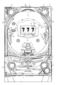
以下、本発明の第1の実施の形態を、図面を参照して説明する。まず、遊技機の一例であるパチンコ遊技機1の全体の構成について説明する。図1はパチンコ遊技機1を正面からみた正面図である。
DESCRIPTION OF EXEMPLARY EMBODIMENTS Hereinafter, a first embodiment of the invention will be described with reference to the drawings. First, the overall configuration of a
パチンコ遊技機1は、縦長の方形状に形成された外枠(図示せず)と、外枠の内側に開閉可能に取り付けられた遊技枠とで構成される。また、パチンコ遊技機1は、遊技枠に開閉可能に設けられている額縁状に形成されたガラス扉枠2を有する。遊技枠は、外枠に対して開閉自在に設置される前面枠(図示せず)と、機構部品等が取り付けられる機構板(図示せず)と、それらに取り付けられる種々の部品(後述する遊技盤6を除く)とを含む構造体である。
The
ガラス扉枠2の下部表面には打球供給皿(上皿)3がある。打球供給皿3の下部には、打球供給皿3に収容しきれない遊技球を貯留する余剰球受皿4や、打球を発射する打球操作ハンドル(操作ノブ)5が設けられている。また、ガラス扉枠2の背面には、遊技盤6が着脱可能に取り付けられている。なお、遊技盤6は、それを構成する板状体と、その板状体に取り付けられた種々の部品とを含む構造体である。また、遊技盤6の前面には、打ち込まれた遊技球が流下可能な遊技領域7が形成されている。
On the lower surface of the
余剰球受皿(下皿)4を形成する部材には、例えば下皿本体の上面における手前側の所定位置(例えば下皿の中央部分)などに、スティック形状(棒形状)に構成され、遊技者が把持して複数方向(前後左右)に傾倒操作が可能なスティックコントローラ122が取り付けられている。なお、スティックコントローラ122には、遊技者がスティックコントローラ122の操作桿を操作手(例えば左手など)で把持した状態において、所定の操作指(例えば人差し指など)で押引操作することなどにより所定の指示操作が可能なトリガボタン121(図3を参照)が設けられ、スティックコントローラ122の操作桿の内部には、トリガボタン121に対する押引操作などによる所定の指示操作を検知するトリガセンサ125(図3を参照)が内蔵されている。また、スティックコントローラ122の下部における下皿の本体内部などには、操作桿に対する傾倒操作を検知する傾倒方向センサユニット123(図3を参照)が設けられている。また、スティックコントローラ122には、スティックコントローラ122を振動動作させるためのバイブレータ用モータ126(図3を参照)が内蔵されている。
The member that forms the extra ball tray (lower tray) 4 is configured in a stick shape (bar shape), for example, at a predetermined position on the front side of the upper surface of the lower tray main body (for example, the central portion of the lower tray). Is attached to the
打球供給皿(上皿)3を形成する部材には、例えば上皿本体の上面における手前側の所定位置(例えばスティックコントローラ122の上方)などに、遊技者が押下操作などにより所定の指示操作を可能なプッシュボタン120が設けられている。プッシュボタン120は、遊技者からの押下操作などによる所定の指示操作を、機械的、電気的、あるいは、電磁的に、検出できるように構成されていればよい。プッシュボタン120の設置位置における上皿の本体内部などには、プッシュボタン120に対してなされた遊技者の操作行為を検知するプッシュセンサ124(図3を参照)が設けられていればよい。図1に示す構成例では、プッシュボタン120とスティックコントローラ122の取付位置が、上皿及び下皿の中央部分において上下の位置関係にある。これに対して、上下の位置関係を保ったまま、プッシュボタン120及びスティックコントローラ122の取付位置を、上皿及び下皿において左右のいずれかに寄せた位置としてもよい。あるいは、プッシュボタン120とスティックコントローラ122の取付位置が上下の位置関係にはなく、例えば左右の位置関係にあるものとしてもよい。
The member that forms the hitting ball supply tray (upper plate) 3 is subjected to a predetermined instruction operation, for example, by a player pressing a predetermined position on the upper surface of the upper plate body (for example, above the stick controller 122). A
遊技領域7の中央付近には、液晶表示装置(LCD)で構成された演出表示装置9が設けられている。演出表示装置9の表示画面には、第1特別図柄または第2特別図柄の可変表示に同期した演出図柄の可変表示を行う演出図柄表示領域がある。よって、演出表示装置9は、演出図柄の可変表示を行う可変表示装置に相当する。演出図柄表示領域には、例えば「左」、「中」、「右」の3つの装飾用(演出用)の演出図柄を可変表示する図柄表示エリアがある。図柄表示エリアには「左」、「中」、「右」の各図柄表示エリアがあるが、図柄表示エリアの位置は、演出表示装置9の表示画面において固定的でなくてもよいし、図柄表示エリアの3つ領域が離れてもよい。演出表示装置9は、演出制御基板に搭載されている演出制御用マイクロコンピュータによって制御される。演出制御用マイクロコンピュータが、第1特別図柄表示器8aで第1特別図柄の可変表示が実行されているときに、その可変表示に伴って演出表示装置9で演出表示を実行させ、第2特別図柄表示器8bで第2特別図柄の可変表示が実行されているときに、その可変表示に伴って演出表示装置9で演出表示を実行させるので、遊技の進行状況を把握しやすくすることができる。
An
また、演出表示装置9において、最終停止図柄(例えば左右中図柄のうち中図柄)となる図柄以外の図柄が、所定時間継続して、大当り図柄(例えば左中右の図柄が同じ図柄で揃った図柄の組み合わせ)と一致している状態で停止、揺動、拡大縮小もしくは変形している状態、または、複数の図柄が同一図柄で同期して変動したり、表示図柄の位置が入れ替わっていたりして、最終結果が表示される前で大当り発生の可能性が継続している状態(以下、これらの状態をリーチ状態という。)において行われる演出をリーチ演出という。また、リーチ状態やその様子をリーチ態様という。さらに、リーチ演出を含む可変表示をリーチ可変表示という。そして、演出表示装置9に変動表示される図柄の表示結果が大当り図柄でない場合には「はずれ」となり、変動表示状態は終了する。遊技者は、大当りをいかにして発生させるかを楽しみつつ遊技を行う。
Further, in the
演出表示装置9の表示画面の右上方部には、演出図柄と後述する特別図柄および普通図柄とに次ぐ第4図柄を表示する第4図柄表示領域9c,9dが設けられている。この実施の形態では、後述する第1特別図柄の変動表示に同期して第1特別図柄用の第4図柄の変動表示が行われる第1特別図柄用の第4図柄表示領域9cと、第2特別図柄の変動表示に同期して第2特別図柄用の第4図柄の変動表示が行われる第2特別図柄用の第4図柄表示領域9dとが設けられている。
In the upper right part of the display screen of the
この実施の形態では、特別図柄の変動表示に同期して演出図柄の変動表示が実行されるのであるが(ただし、正確には、演出図柄の変動表示は、演出制御用マイクロコンピュータ100側で変動パターンコマンドにもとづいて認識した変動時間を計測することによって行われる。)、演出表示装置9を用いた演出を行う場合、例えば、演出図柄の変動表示を含む演出内容が画面上から一瞬消えるような演出が行われたり、可動物が画面上の全部または一部を遮蔽するような演出が行われるなど、演出態様が多様化してきている。そのため、演出表示装置9上の表示画面を見ていても、現在変動表示中の状態であるのか否か認識しにくい場合も生じている。そこで、この実施の形態では、演出表示装置9の表示画面の一部でさらに第4図柄の変動表示を行うことによって、第4図柄の状態を確認することにより現在変動表示中の状態であるのか否かを確実に認識可能としている。なお、第4図柄は、常に一定の動作で変動表示され、画面上から消えたり遮蔽物で遮蔽することはないため、常に視認することができる。
In this embodiment, the variation display of the effect symbol is executed in synchronization with the variation display of the special symbol (however, to be precise, the variation display of the effect symbol is varied on the
なお、第1特別図柄用の第4図柄と第2特別図柄用の第4図柄とを、第4図柄と総称することがあり、第1特別図柄用の第4図柄表示領域9cと第2特別図柄用の第4図柄表示領域9dを、第4図柄表示領域と総称することがある。
The 4th symbol for the first special symbol and the 4th symbol for the 2nd special symbol may be collectively referred to as the 4th symbol, and the 4th
第4図柄の変動(可変表示)は、第4図柄表示領域9c,9dを所定の表示色(例えば、青色)で一定の時間間隔で点灯と消灯とを繰り返す状態を継続することによって実現される。第1特別図柄表示器8aにおける第1特別図柄の可変表示と、第1特別図柄用の第4図柄表示領域9cにおける第1特別図柄用の第4図柄の可変表示とは同期している。第2特別図柄表示器8bにおける第2特別図柄の可変表示と、第2特別図柄用の第4図柄表示領域9dにおける第2特別図柄用の第4図柄の可変表示とは同期している。同期とは、可変表示の開始時点および終了時点が同じであって、可変表示の期間が同じであることをいう。
The variation (variable display) of the fourth symbol is realized by continuing the state where the fourth
また、第1特別図柄表示器8aにおいて大当り図柄が停止表示されるときには、第1特別図柄用の第4図柄表示領域9cにおいて大当りを想起させる表示色(はずれとは異なる表示色。例えば、はずれのときには青色で表示されるのに対して、大当りのときには赤色)で表示される。なお、大当りの種類(確変大当りや通常大当りのいずれであるか)に応じて表示色を異ならせてもよい。また、大入賞口への遊技球の入賞を期待できる大当り(例えば、突然通常大当り以外の大当り)であるか否かに応じて表示色を異ならせてもよく、ラウンド数の異なる複数種類の大当りに制御可能である場合には、大当り遊技において継続されるラウンド数に応じて表示色を異ならせてもよい。また、この実施の形態のように、各大当りのラウンド数が同じであっても、例えば、1ラウンドあたりの大入賞口の開放時間が短く(例えば1秒)、実質的に大入賞口への遊技球の入賞を期待できない大当りと、1ラウンドあたりの大入賞口の開放時間が長く(例えば29秒)、実質的に大入賞口への遊技球の入賞を期待できる大当りとがある場合には、実質的に大入賞口への遊技球の入賞を期待できるか否かに応じて表示色を異ならせてもよい。また、例えば、1ラウンドあたりの大入賞口の開放回数が異なることによって、実質的に大入賞口への遊技球の入賞を期待できる大当りと期待できない大当りがある場合にも、実質的に大入賞口への遊技球の入賞を期待できるか否かに応じて表示色を異ならせてもよい。
When the big hit symbol is stopped and displayed on the first
また、第2特別図柄表示器8bにおいて大当り図柄が停止表示されるときには、第2特別図柄用の第4図柄表示領域9dにおいて大当りを想起させる表示色(はずれとは異なる表示色。例えば、はずれのときには青色で表示されるのに対して、大当りのときには赤色)で表示される。なお、大当りの種類(確変大当りや通常大当りのいずれであるか)に応じて表示色を異ならせてもよい。また、大入賞口への遊技球の入賞を期待できる大当り(例えば、突然通常大当り以外の大当り)であるか否かに応じて表示色を異ならせてもよく、ラウンド数の異なる複数種類の大当りに制御可能である場合には、大当り遊技において継続されるラウンド数に応じて表示色を異ならせてもよい。また、この実施の形態のように、各大当りのラウンド数が同じであっても、例えば、1ラウンドあたりの大入賞口の開放時間が短く(例えば1秒)、実質的に大入賞口への遊技球の入賞を期待できない大当りと、1ラウンドあたりの大入賞口の開放時間が長く(例えば29秒)、実質的に大入賞口への遊技球の入賞を期待できる大当りとがある場合には、実質的に大入賞口への遊技球の入賞を期待できるか否かに応じて表示色を異ならせてもよい。また、例えば、1ラウンドあたりの大入賞口の開放回数が異なることによって、実質的に大入賞口への遊技球の入賞を期待できる大当りと期待できない大当りがある場合にも、実質的に大入賞口への遊技球の入賞を期待できるか否かに応じて表示色を異ならせてもよい。
Further, when the big hit symbol is stopped and displayed on the second special symbol display 8b, the display color reminiscent of the big hit in the fourth
なお、第4図柄表示領域9c,9dの消灯時の表示色は、消灯したときに背景画像と同化して見えなくなることを防止するために、背景画像とは異なる表示色(例えば、黒色)であることが望ましい。
The display colors when the fourth
なお、この実施の形態では、第4図柄表示領域を演出表示装置9の表示画面の一部に設ける場合を示しているが、演出表示装置9とは別に、ランプやLEDなどの発光体を用いて第4図柄表示領域を実現するようにしてもよい。この場合、例えば、第4図柄の変動(可変表示)を、2つのLEDが交互に点灯する状態を継続することによって実現されるようにしてもよく、2つのLEDのうちのいずれのLEDが停止表示されたかによって大当り図柄が停止表示されたか否かを表すようにしてもよい。
In this embodiment, the case where the 4th symbol display area is provided on a part of the display screen of the
また、この実施の形態では、第1特別図柄と第2特別図柄とにそれぞれ対応させて別々の第4図柄表示領域9c,9dを備える場合を示しているが、第1特別図柄と第2特別図柄とに対して共通の第4図柄表示領域を演出表示装置9の表示画面の一部に設けるようにしてもよい。また、第1特別図柄と第2特別図柄とに対して共通の第4図柄表示領域をランプやLEDなどの発光体を用いて実現するようにしてもよい。この場合、第1特別図柄の変動表示に同期して第4図柄の変動表示を実行するときと、第2特別図柄の変動表示に同期して第4図柄の変動表示を実行するときとで、例えば、一定の時間間隔で異なる表示色の表示を点灯および消灯を繰り返すような表示を行うことによって、第4図柄の変動表示を区別して実行するようにしてもよい。また、第1特別図柄の変動表示に同期して第4図柄の変動表示を実行するときと、第2特別図柄の変動表示に同期して第4図柄の変動表示を実行するときとで、例えば、異なる時間間隔で点灯および消灯を繰り返すような表示を行うことによって、第4図柄の変動表示を区別して実行するようにしてもよい。また、例えば、第1特別図柄の変動表示に対応して停止図柄を導出表示するときと、第2特別図柄の変動表示に対応して停止図柄を導出表示するときとで、同じ大当り図柄であっても異なる態様の停止図柄を停止表示するようにしてもよい。
Further, in this embodiment, a case is shown in which separate fourth
演出表示装置9の右方には、識別情報としての第1特別図柄を可変表示する第1特別図柄表示器(第1可変表示部)8aが設けられている。この実施の形態では、第1特別図柄表示器8aは、0〜9の数字を可変表示可能な簡易で小型の表示器(例えば7セグメントLED)で実現されている。すなわち、第1特別図柄表示器8aは、0〜9の数字(または、記号)を可変表示するように構成されている。また、演出表示装置9の右方(第1特別図柄表示器8aの右隣)には、識別情報としての第2特別図柄を可変表示する第2特別図柄表示器(第2可変表示部)8bも設けられている。第2特別図柄表示器8bは、0〜9の数字を可変表示可能な簡易で小型の表示器(例えば7セグメントLED)で実現されている。すなわち、第2特別図柄表示器8bは、0〜9の数字(または、記号)を可変表示するように構成されている。
On the right side of the
小型の表示器は、例えば方形状に形成されている。また、この実施の形態では、第1特別図柄の種類と第2特別図柄の種類とは同じ(例えば、ともに0〜9の数字)であるが、種類が異なっていてもよい。また、第1特別図柄表示器8aおよび第2特別図柄表示器8bは、それぞれ、例えば、00〜99の数字(または、2桁の記号)を可変表示するように構成されていてもよい。
The small display is formed in a square shape, for example. In this embodiment, the type of the first special symbol and the type of the second special symbol are the same (for example, both 0 to 9), but the types may be different. Further, the first
以下、第1特別図柄と第2特別図柄とを特別図柄と総称することがあり、第1特別図柄表示器8aと第2特別図柄表示器8bとを特別図柄表示器(可変表示部)と総称することがある。
Hereinafter, the first special symbol and the second special symbol may be collectively referred to as a special symbol, and the first
なお、この実施の形態では、2つの特別図柄表示器8a,8bを備える場合を示しているが、遊技機は、特別図柄表示器を1つのみ備えるものであってもよい。
Although this embodiment shows a case where two
第1特別図柄または第2特別図柄の可変表示は、可変表示の実行条件である第1始動条件または第2始動条件が成立(例えば、遊技球が第1始動入賞口13または第2始動入賞口14を通過(入賞を含む)したこと)した後、可変表示の開始条件(例えば、保留記憶数が0でない場合であって、第1特別図柄および第2特別図柄の可変表示が実行されていない状態であり、かつ、大当り遊技が実行されていない状態)が成立したことにもとづいて開始され、可変表示時間(変動時間)が経過すると表示結果(停止図柄)を導出表示する。なお、遊技球が通過するとは、入賞口やゲートなどのあらかじめ入賞領域として定められている領域を遊技球が通過したことであり、入賞口に遊技球が入った(入賞した)ことを含む概念である。また、表示結果を導出表示するとは、図柄(識別情報の例)を最終的に停止表示させることである。
For the variable display of the first special symbol or the second special symbol, the first start condition or the second start condition, which is the variable display execution condition, is satisfied (for example, the game ball has the first
演出表示装置9の下方には、第1始動入賞口13を有する入賞装置が設けられている。第1始動入賞口13に入賞した遊技球は、遊技盤6の背面に導かれ、第1始動口スイッチ13aによって検出される。
A winning device having a first
また、第1始動入賞口(第1始動口)13を有する入賞装置の下方には、遊技球が入賞可能な第2始動入賞口14を有する可変入賞球装置15が設けられている。第2始動入賞口(第2始動口)14に入賞した遊技球は、遊技盤6の背面に導かれ、第2始動口スイッチ14aによって検出される。可変入賞球装置15は、ソレノイド16によって開状態とされる。可変入賞球装置15が開状態になることによって、遊技球が第2始動入賞口14に入賞可能になり(始動入賞し易くなり)、遊技者にとって有利な状態になる。可変入賞球装置15が開状態になっている状態では、第1始動入賞口13よりも、第2始動入賞口14に遊技球が入賞しやすい。また、可変入賞球装置15が閉状態になっている状態では、遊技球は第2始動入賞口14に入賞しない。従って、可変入賞球装置15が閉状態になっている状態では、第2始動入賞口14よりも、第1始動入賞口13に遊技球が入賞しやすい。なお、可変入賞球装置15が閉状態になっている状態において、入賞はしづらいものの、入賞することは可能である(すなわち、遊技球が入賞しにくい)ように構成されていてもよい。
A variable winning
以下、第1始動入賞口13と第2始動入賞口14とを総称して始動入賞口または始動口ということがある。
Hereinafter, the first
可変入賞球装置15が開放状態に制御されているときには可変入賞球装置15に向かう遊技球は第2始動入賞口14に極めて入賞しやすい。そして、第1始動入賞口13は演出表示装置9の直下に設けられているが、演出表示装置9の下端と第1始動入賞口13との間の間隔をさらに狭めたり、第1始動入賞口13の周辺で釘を密に配置したり、第1始動入賞口13の周辺での釘配列を遊技球を第1始動入賞口13に導きづらくして、第2始動入賞口14の入賞率の方を第1始動入賞口13の入賞率よりもより高くするようにしてもよい。
When the variable winning
なお、この実施の形態では、図1に示すように、第2始動入賞口14に対してのみ開閉動作を行う可変入賞球装置15が設けられているが、第1始動入賞口13および第2始動入賞口14のいずれについても開閉動作を行う可変入賞球装置が設けられている構成であってもよい。
In this embodiment, as shown in FIG. 1, the variable winning
第2特別図柄表示器8bの上方には、第2始動入賞口14に入った有効入賞球数すなわち第2保留記憶数を表示する4つの表示器からなる第2特別図柄保留記憶表示器18bが設けられている。第2特別図柄保留記憶表示器18bは、有効始動入賞がある毎に、点灯する表示器の数を1増やす。そして、第2特別図柄表示器8bでの可変表示が開始される毎に、点灯する表示器の数を1減らす。
Above the second special symbol display 8b, there is a second special symbol
また、第2特別図柄保留記憶表示器18bのさらに上方には、第1始動入賞口13に入った有効入賞球数すなわち第1保留記憶数(保留記憶を、始動記憶または始動入賞記憶ともいう。)を表示する4つの表示器からなる第1特別図柄保留記憶表示器18aが設けられている。第1特別図柄保留記憶表示器18aは、有効始動入賞がある毎に、点灯する表示器の数を1増やす。そして、第1特別図柄表示器8aでの可変表示が開始される毎に、点灯する表示器の数を1減らす。
Further, above the second special symbol
また、演出表示装置9の表示画面の下部には、第1保留記憶数を表示する第1保留記憶表示部18cと、第2保留記憶数を表示する第2保留記憶表示部18dとが設けられている。なお、第1保留記憶数と第2保留記憶数との合計である合計数(合算保留記憶数)を表示する領域(合算保留記憶表示部)が設けられるようにしてもよい。そのように、合計数を表示する合算保留記憶表示部が設けられているようにすれば、可変表示の開始条件が成立していない実行条件の成立数の合計を把握しやすくすることができる。
Also, at the lower part of the display screen of the
演出表示装置9は、第1特別図柄表示器8aによる第1特別図柄の可変表示時間中、および第2特別図柄表示器8bによる第2特別図柄の可変表示時間中に、装飾用(演出用)の図柄としての演出図柄の可変表示を行う。第1特別図柄表示器8aにおける第1特別図柄の可変表示と、演出表示装置9における演出図柄の可変表示とは同期している。また、第2特別図柄表示器8bにおける第2特別図柄の可変表示と、演出表示装置9における演出図柄の可変表示とは同期している。また、第1特別図柄表示器8aにおいて大当り図柄が停止表示されるときと、第2特別図柄表示器8bにおいて大当り図柄が停止表示されるときには、演出表示装置9において大当りを想起させるような演出図柄の組み合わせが停止表示される。
The
また、図1に示すように、可変入賞球装置15の下方には、大入賞口を形成する特別可変入賞球装置20が設けられている。特別可変入賞球装置20は開閉板を備え、第1特別図柄表示器8aまたは第2特別図柄表示器8bに特定表示結果(大当り図柄)が導出表示された後に、演出表示装置9の右方に設けられた特定ゲート200に遊技球が進入したときに生起する特定遊技状態(大当り遊技状態)においてソレノイド21によって開閉板が開放状態に制御されることによって、入賞領域となる大入賞口が開放状態になる。大入賞口に入賞した遊技球はカウントスイッチ23で検出される。
Further, as shown in FIG. 1, a special variable winning
演出表示装置9の左方には、普通図柄を可変表示する普通図柄表示器10が設けられている。この実施の形態では、普通図柄表示器10は、0〜9の数字を可変表示可能な簡易で小型の表示器(例えば7セグメントLED)で実現されている。すなわち、普通図柄表示器10は、0〜9の数字(または、記号)を可変表示するように構成されている。また、小型の表示器は、例えば方形状に形成されている。なお、普通図柄表示器10は、例えば、00〜99の数字(または、2桁の記号)を可変表示するように構成されていてもよい。また、普通図柄表示器10は、7セグメントLEDなどにかぎらず、例えば、所定の記号表示を点灯表示可能な表示器(例えば、「○」や「×」を交互に点灯表示可能な装飾ランプ)で構成されていてもよい。
On the left side of the
遊技球がゲート32を通過しゲートスイッチ32aで検出されると、普通図柄表示器10の表示の可変表示が開始される。そして、普通図柄表示器10における停止図柄が所定の図柄(当り図柄。例えば、図柄「7」。)である場合に、可変入賞球装置15が所定回数、所定時間だけ開状態になる。すなわち、可変入賞球装置15の状態は、普通図柄の停止図柄が当り図柄である場合に、遊技者にとって不利な状態から有利な状態(第2始動入賞口14に遊技球が入賞可能な状態)に変化する。普通図柄表示器10の近傍には、ゲート32を通過した入賞球数を表示する4つのLEDによる表示部を有する普通図柄保留記憶表示器41が設けられている。ゲート32への遊技球の通過がある毎に、すなわちゲートスイッチ32aによって遊技球が検出される毎に、普通図柄保留記憶表示器41は点灯するLEDを1増やす。そして、普通図柄表示器10の可変表示が開始される毎に、点灯するLEDを1減らす。さらに、通常状態に比べて大当りとすることに決定される確率が高い状態である確変状態(通常状態と比較して、特別図柄の変動表示結果として大当りと判定される確率が高められた状態)では、普通図柄表示器10における停止図柄が当り図柄になる確率が高められるとともに、可変入賞球装置15の開放時間と開放回数が高められる。また、確変状態ではないが図柄の変動時間が短縮されている時短状態(特別図柄の可変表示時間が短縮される遊技状態)でも、可変入賞球装置15の開放時間と開放回数が高められる。
When the game ball passes through the
遊技盤6の下部には、入賞しなかった打球が取り込まれるアウト口26がある。また、遊技領域7の外側の左右上部および左右下部には、所定の音声出力として効果音や音声を発声する4つのスピーカ27が設けられている。遊技領域7の外周には、前面枠に設けられた枠LED28が設けられている。
At the lower part of the
遊技機には、遊技者が打球操作ハンドル5を操作することに応じて駆動モータを駆動し、駆動モータの回転力を利用して遊技球を遊技領域7に発射する打球発射装置(図示せず)が設けられている。打球発射装置から発射された遊技球は、遊技領域7を囲むように円形状に形成された打球レールを通って遊技領域7に入り、その後、遊技領域7を下りてくる。遊技球が第1始動入賞口13に入り第1始動口スイッチ13aで検出されると、第1特別図柄の可変表示を開始できる状態であれば(例えば、特別図柄の可変表示が終了し、第1の開始条件が成立したこと)、第1特別図柄表示器8aにおいて第1特別図柄の可変表示(変動)が開始されるとともに、演出表示装置9において演出図柄の可変表示が開始される。すなわち、第1特別図柄および演出図柄の可変表示は、第1始動入賞口13への入賞に対応する。第1特別図柄の可変表示を開始できる状態でなければ、第1保留記憶数が上限値に達していないことを条件として、第1保留記憶数を1増やす。
In the gaming machine, a ball striking device (not shown) that drives a driving motor in response to a player operating the batting operation handle 5 and uses the rotational force of the driving motor to launch a gaming ball to the gaming area 7. ) Is provided. A game ball launched from the ball striking device enters the
遊技球が第2始動入賞口14に入り第2始動口スイッチ14aで検出されると、第2特別図柄の可変表示を開始できる状態であれば(例えば、特別図柄の可変表示が終了し、第2の開始条件が成立したこと)、第2特別図柄表示器8bにおいて第2特別図柄の可変表示(変動)が開始されるとともに、演出表示装置9において演出図柄の可変表示が開始される。すなわち、第2特別図柄および演出図柄の可変表示は、第2始動入賞口14への入賞に対応する。第2特別図柄の可変表示を開始できる状態でなければ、第2保留記憶数が上限値に達していないことを条件として、第2保留記憶数を1増やす。
When the game ball enters the second
この実施の形態では、確変大当りとなった場合には、遊技状態を高確率状態に移行するとともに、遊技球が始動入賞しやすくなる(すなわち、特別図柄表示器8a,8bや演出表示装置9における可変表示の実行条件が成立しやすくなる)ように制御された遊技状態である高ベース状態に移行する。また、遊技状態が時短状態に移行されたときも、高ベース状態に移行する。高ベース状態である場合には、例えば、高ベース状態でない場合と比較して、可変入賞球装置15が開状態となる頻度が高められたり、可変入賞球装置15が開状態となる時間が延長されたりして、始動入賞しやすくなる。
In this embodiment, when the probability variation is a big hit, the game state is shifted to a high probability state, and the game ball is easily started and won (that is, in the
なお、可変入賞球装置15が開状態となる時間を延長する(開放延長状態ともいう)のでなく、普通図柄表示器10における停止図柄が当り図柄になる確率が高められる普通図柄確変状態に移行することによって、高ベース状態に移行してもよい。普通図柄表示器10における停止図柄が所定の図柄(当り図柄)となると、可変入賞球装置15が所定回数、所定時間だけ開状態になる。この場合、普通図柄確変状態に移行制御することによって、普通図柄表示器10における停止図柄が当り図柄になる確率が高められ、可変入賞球装置15が開状態となる頻度が高まる。従って、普通図柄確変状態に移行すれば、可変入賞球装置15の開放時間と開放回数が高められ、始動入賞しやすい状態(高ベース状態)となる。すなわち、可変入賞球装置15の開放時間と開放回数は、普通図柄の停止図柄が当り図柄であったり、特別図柄の停止図柄が確変図柄である場合等に高められ、遊技者にとって不利な状態から有利な状態(始動入賞しやすい状態)に変化する。なお、開放回数が高められることは、閉状態から開状態になることも含む概念である。
Instead of extending the time during which the variable winning
また、普通図柄表示器10における普通図柄の変動時間(可変表示期間)が短縮される普通図柄時短状態に移行することによって、高ベース状態に移行してもよい。普通図柄時短状態では、普通図柄の変動時間が短縮されるので、普通図柄の変動が開始される頻度が高くなり、結果として普通図柄が当りとなる頻度が高くなる。従って、普通図柄が当たりとなる頻度が高くなることによって、可変入賞球装置15が開状態となる頻度が高くなり、始動入賞しやすい状態(高ベース状態)となる。
Moreover, you may transfer to a high base state by shifting to the normal symbol time short state where the fluctuation time (variable display period) of the normal symbol in the
また、特別図柄や演出図柄の変動時間(可変表示期間)が短縮される時短状態に移行することによって、特別図柄や演出図柄の変動時間が短縮されるので、特別図柄や演出図柄の変動が開始される頻度が高くなり(換言すれば、保留記憶の消化が速くなる。)、無効な始動入賞が生じてしまう事態を低減することができる。従って、有効な始動入賞が発生しやすくなり、結果として、大当り遊技が行われる可能性が高まる。 In addition, the change time of special symbols and production symbols will be shortened by shifting to the short time state when the variation time (variable display period) of special symbols and production symbols is shortened. The frequency of being played (in other words, the digestion of the reserved memory becomes faster), and the situation where an invalid start prize is generated can be reduced. Therefore, an effective start winning is likely to occur, and as a result, the possibility of a big hit game being increased.
さらに、上記に示した全ての状態(開放延長状態、普通図柄確変状態、普通図柄時短状態および特別図柄時短状態)に移行させることによって、始動入賞しやすくなる(高ベース状態に移行する)ようにしてもよい。また、上記に示した各状態(開放延長状態、普通図柄確変状態、普通図柄時短状態および特別図柄時短状態)のうちのいずれか複数の状態に移行させることによって、始動入賞しやすくなる(高ベース状態に移行する)ようにしてもよい。また、上記に示した各状態(開放延長状態、普通図柄確変状態、普通図柄時短状態および特別図柄時短状態)のうちのいずれか1つの状態にのみ移行させることによって、始動入賞しやすくなる(高ベース状態に移行する)ようにしてもよい。 Furthermore, by making transitions to all the states shown above (open extended state, normal symbol probability change state, normal symbol short time state, and special symbol short time state), it will be easier to win a start (shift to a high base state). May be. In addition, it is easier to win a start (high base) by shifting to any one of the above states (open extended state, normal symbol probability changing state, normal symbol short time state, and special symbol short time state). Transition to a state). In addition, it is easier to win a start by shifting to any one of the above states (open extended state, normal symbol probability changing state, normal symbol short time state, and special symbol short time state). You may make it move to a base state.
また、演出表示装置9の右方には特定ゲート200が設けられ、特定ゲート200に進入した遊技球は特定ゲートスイッチ200aで検出される。この実施の形態では、第1特別図柄表示器8aや第2特別図柄表示器8b、演出表示装置9に大当り図柄が導出表示されて大当りが発生したときに、直ちに大当り遊技状態が開始されるのではなく、大当り図柄が導出表示された後、遊技球が特定ゲート200に進入し特定ゲートスイッチ200aで検出されたことにもとづいて大当り遊技状態が開始される。
Further, a
図2は、主基板(遊技制御基板)31における回路構成の一例を示すブロック図である。なお、図2は、払出制御基板37および演出制御基板80等も示されている。主基板31には、プログラムに従ってパチンコ遊技機1を制御する遊技制御用マイクロコンピュータ(遊技制御手段に相当)560が搭載されている。遊技制御用マイクロコンピュータ560は、ゲーム制御(遊技進行制御)用のプログラム等を記憶するROM54、ワークメモリとして使用される記憶手段としてのRAM55、プログラムに従って制御動作を行うCPU56およびI/Oポート部57を含む。この実施の形態では、ROM54およびRAM55は遊技制御用マイクロコンピュータ560に内蔵されている。すなわち、遊技制御用マイクロコンピュータ560は、1チップマイクロコンピュータである。1チップマイクロコンピュータには、少なくともCPU56のほかRAM55が内蔵されていればよく、ROM54は外付けであっても内蔵されていてもよい。また、I/Oポート部57は、外付けであってもよい。遊技制御用マイクロコンピュータ560には、さらに、ハードウェア乱数(ハードウェア回路が発生する乱数)を発生する乱数回路503が内蔵されている。
FIG. 2 is a block diagram showing an example of the circuit configuration of the main board (game control board) 31. FIG. 2 also shows a
また、RAM55は、その一部または全部が電源基板910において作成されるバックアップ電源によってバックアップされている不揮発性記憶手段としてのバックアップRAMである。すなわち、遊技機に対する電力供給が停止しても、所定期間(バックアップ電源としてのコンデンサが放電してバックアップ電源が電力供給不能になるまで)は、RAM55の一部または全部の内容は保存される。特に、少なくとも、遊技状態すなわち遊技制御手段の制御状態に応じたデータと未払出賞球数を示すデータは、バックアップRAMに保存される。遊技制御手段の制御状態に応じたデータとは、停電等が生じた後に復旧した場合に、そのデータにもとづいて、制御状態を停電等の発生前に復旧させるために必要なデータである。また、制御状態に応じたデータと未払出賞球数を示すデータとを遊技の進行状態を示すデータと定義する。なお、この実施の形態では、RAM55の全部が、電源バックアップされているとする。
The
この実施の形態では、バックアップRAMであるRAM55には、遊技制御手段の制御状態に応じたデータとして、特別図柄プロセスフラグや確変フラグなどに加えて、少なくとも、特別図柄の表示結果(大当りと決定したか否か(例えば、大当りフラグ)や、大当り種別の決定結果)およびラウンド数カウンタの値が記憶される。そして、後述するように、大当り遊技中に停電が発生した後に停電復旧時の処理が行われる場合には、バックアップされた特別図柄の表示結果とラウンド数カウンタの値で特定されるラウンド数とを含む停電復旧指定コマンドが送信される(後述するステップS43,S44参照)。
In this embodiment, the
なお、遊技制御用マイクロコンピュータ560においてCPU56がROM54に格納されているプログラムに従って制御を実行するので、以下、遊技制御用マイクロコンピュータ560(またはCPU56)が実行する(または、処理を行う)ということは、具体的には、CPU56がプログラムに従って制御を実行することである。このことは、主基板31以外の他の基板に搭載されているマイクロコンピュータについても同様である。
In the
乱数回路503は、特別図柄の可変表示の表示結果により大当りとするか否か判定するための判定用の乱数を発生するために用いられるハードウェア回路である。乱数回路503は、初期値(例えば、0)と上限値(例えば、65535)とが設定された数値範囲内で、数値データを、設定された更新規則に従って更新し、ランダムなタイミングで発生する始動入賞時が数値データの読出(抽出)時であることにもとづいて、読出される数値データが乱数値となる乱数発生機能を有する。 The random number circuit 503 is a hardware circuit that is used to generate a random number for determination to determine whether or not to win a jackpot based on a display result of variable symbol special display. The random number circuit 503 updates numerical data in accordance with a set update rule within a numerical range in which an initial value (for example, 0) and an upper limit value (for example, 65535) are set, and starts at a random timing Based on the fact that the winning time is the reading (extraction) of the numerical data, it has a random number generation function in which the numerical data to be read becomes a random value.
乱数回路503は、数値データの更新範囲の選択設定機能(初期値の選択設定機能、および、上限値の選択設定機能)、数値データの更新規則の選択設定機能、および数値データの更新規則の選択切換え機能等の各種の機能を有する。このような機能によって、生成する乱数のランダム性を向上させることができる。 The random number circuit 503 includes a numeric data update range selection setting function (initial value selection setting function and upper limit value selection setting function), numeric data update rule selection setting function, and numeric data update rule selection. It has various functions such as a switching function. With such a function, the randomness of the generated random numbers can be improved.
また、遊技制御用マイクロコンピュータ560は、乱数回路503が更新する数値データの初期値を設定する機能を有している。例えば、ROM54等の所定の記憶領域に記憶された遊技制御用マイクロコンピュータ560のIDナンバ(遊技制御用マイクロコンピュータ560の各製品ごとに異なる数値で付与されたIDナンバ)を用いて所定の演算を行なって得られた数値データを、乱数回路503が更新する数値データの初期値として設定する。そのような処理を行うことによって、乱数回路503が発生する乱数のランダム性をより向上させることができる。
Further, the
また、ゲートスイッチ32a、第1始動口スイッチ13a、第2始動口スイッチ14a、カウントスイッチ23、特定ゲートスイッチ200aからの検出信号を遊技制御用マイクロコンピュータ560に与える入力ドライバ回路58も主基板31に搭載されている。また、可変入賞球装置15を開閉するソレノイド16、および大入賞口を形成する特別可変入賞球装置20を開閉するソレノイド21を遊技制御用マイクロコンピュータ560からの指令に従って駆動する出力回路59も主基板31に搭載されている。
Further, an input driver circuit 58 for supplying detection signals from the
また、遊技制御用マイクロコンピュータ560は、特別図柄を可変表示する第1特別図柄表示器8a、第2特別図柄表示器8b、普通図柄を可変表示する普通図柄表示器10、第1特別図柄保留記憶表示器18a、第2特別図柄保留記憶表示器18bおよび普通図柄保留記憶表示器41の表示制御を行う。
In addition, the
なお、大当り遊技状態の発生を示す大当り情報等の情報出力信号を、ターミナル基板160を介して、ホールコンピュータ等の外部装置に対して出力する情報出力回路64も主基板31に搭載されている。
An
この実施の形態では、演出制御基板80に搭載されている演出制御手段(演出制御用マイクロコンピュータで構成される。)が、中継基板77を介して遊技制御用マイクロコンピュータ560から演出内容を指示する演出制御コマンドを受信し、演出図柄を可変表示する演出表示装置9の表示制御を行う。
In this embodiment, the effect control means (configured by the effect control microcomputer) mounted on the
また、演出制御基板80に搭載されている演出制御手段が、ランプドライバ基板35を介して、枠側に設けられている枠LED28の表示制御を行うとともに、音声出力基板70を介してスピーカ27からの音出力の制御を行う。
The effect control means mounted on the
図3は、中継基板77、演出制御基板80、ランプドライバ基板35および音声出力基板70の回路構成例を示すブロック図である。なお、図3に示す例では、ランプドライバ基板35および音声出力基板70には、マイクロコンピュータは搭載されていないが、マイクロコンピュータを搭載してもよい。また、ランプドライバ基板35および音声出力基板70を設けずに、演出制御に関して演出制御基板80のみを設けてもよい。
FIG. 3 is a block diagram illustrating a circuit configuration example of the
演出制御基板80は、演出制御用CPU101、および演出図柄プロセスフラグ等の演出に関する情報を記憶するRAMを含む演出制御用マイクロコンピュータ100を搭載している。なお、RAMは外付けであってもよい。この実施の形態では、演出制御用マイクロコンピュータ100におけるRAMは電源バックアップされていない。演出制御基板80において、演出制御用CPU101は、内蔵または外付けのROM(図示せず)に格納されたプログラムに従って動作し、中継基板77を介して入力される主基板31からの取込信号(演出制御INT信号)に応じて、入力ドライバ102および入力ポート103を介して演出制御コマンドを受信する。また、演出制御用CPU101は、演出制御コマンドにもとづいて、VDP(ビデオディスプレイプロセッサ)109に演出表示装置9の表示制御を行わせる。
The
この実施の形態では、演出制御用マイクロコンピュータ100と共動して演出表示装置9の表示制御を行うVDP109が演出制御基板80に搭載されている。VDP109は、演出制御用マイクロコンピュータ100とは独立したアドレス空間を有し、そこにVRAMをマッピングする。VRAMは、画像データを展開するためのバッファメモリである。そして、VDP109は、VRAM内の画像データをフレームメモリを介して演出表示装置9に出力する。
In this embodiment, a
演出制御用CPU101は、受信した演出制御コマンドに従ってCGROM(図示せず)から必要なデータを読み出すための指令をVDP109に出力する。CGROMは、演出表示装置9に表示されるキャラクタ画像データや動画像データ、具体的には、人物、文字、図形や記号等(演出図柄を含む)、および背景画像のデータをあらかじめ格納しておくためのROMである。VDP109は、演出制御用CPU101の指令に応じて、CGROMから画像データを読み出す。そして、VDP109は、読み出した画像データにもとづいて表示制御を実行する。
The effect control CPU 101 outputs to the VDP 109 a command for reading out necessary data from a CGROM (not shown) in accordance with the received effect control command. The CGROM stores character image data and moving image data displayed on the
演出制御コマンドおよび演出制御INT信号は、演出制御基板80において、まず、入力ドライバ102に入力する。入力ドライバ102は、中継基板77から入力された信号を演出制御基板80の内部に向かう方向にしか通過させない(演出制御基板80の内部から中継基板77への方向には信号を通過させない)信号方向規制手段としての単方向性回路でもある。
The effect control command and the effect control INT signal are first input to the
中継基板77には、主基板31から入力された信号を演出制御基板80に向かう方向にしか通過させない(演出制御基板80から中継基板77への方向には信号を通過させない)信号方向規制手段としての単方向性回路74が搭載されている。単方向性回路として、例えばダイオードやトランジスタが使用される。図3には、ダイオードが例示されている。また、単方向性回路は、各信号毎に設けられる。さらに、単方向性回路である出力ポート571を介して主基板31から演出制御コマンドおよび演出制御INT信号が出力されるので、中継基板77から主基板31の内部に向かう信号が規制される。すなわち、中継基板77からの信号は主基板31の内部(遊技制御用マイクロコンピュータ560側)に入り込まない。なお、出力ポート571は、図2に示されたI/Oポート部57の一部である。また、出力ポート571の外側(中継基板77側)に、さらに、単方向性回路である信号ドライバ回路が設けられていてもよい。
As a signal direction regulating means, the signal inputted from the main board 31 is allowed to pass through the
また、演出制御用CPU101は、スティックコントローラ122のトリガボタン121に対する遊技者の操作行為を検出したことを示す情報信号としての操作検出信号を、トリガセンサ125から、入力ポート106を介して入力する。また、演出制御用CPU101は、プッシュボタン120に対する遊技者の操作行為を検出したことを示す情報信号としての操作検出信号を、プッシュセンサ124から、入力ポート106を介して入力する。また、演出制御用CPU101は、スティックコントローラ122の操作桿に対する遊技者の操作行為を検出したことを示す情報信号としての操作検出信号を、傾倒方向センサユニット123から、入力ポート106を介して入力する。また、演出制御用CPU101は、出力ポート105を介してバイブレータ用モータ126に駆動信号を出力することにより、スティックコントローラ122を振動動作させる。
In addition, the effect control CPU 101 inputs an operation detection signal as an information signal indicating that the player's operation action on the
さらに、演出制御用CPU101は、出力ポート105を介してランプドライバ基板35に対してLEDを駆動する信号を出力する。また、演出制御用CPU101は、出力ポート104を介して音声出力基板70に対して音番号データを出力する。
Further, the effect control CPU 101 outputs a signal for driving the LED to the
ランプドライバ基板35において、LEDを駆動する信号は、入力ドライバ351を介してLEDドライバ352に入力される。LEDドライバ352は、LEDを駆動する信号にもとづいて枠LED28などの発光体に電流を供給する。
In the
音声出力基板70において、音番号データは、入力ドライバ702を介して音声合成用IC703に入力される。音声合成用IC703は、音番号データに応じた音声や効果音を発生し増幅回路705に出力する。増幅回路705は、音声合成用IC703の出力レベルを、ボリューム706で設定されている音量に応じたレベルに増幅した音声信号をスピーカ27に出力する。音声データROM704には、音番号データに応じた制御データが格納されている。音番号データに応じた制御データは、所定期間(例えば演出図柄の変動期間)における効果音または音声の出力態様を時系列的に示すデータの集まりである。
In the
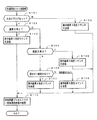
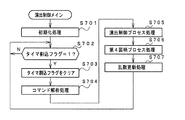
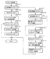
次に遊技機の動作について説明する。図4は、遊技機に対して電力供給が開始され遊技制御用マイクロコンピュータ560へのリセット信号がハイレベルになったことに応じて遊技制御用マイクロコンピュータ560のCPU56が実行するメイン処理を示すフローチャートである。リセット信号が入力されるリセット端子の入力レベルがハイレベルになると、遊技制御用マイクロコンピュータ560のCPU56は、プログラムの内容が正当か否かを確認するための処理であるセキュリティチェック処理を実行した後、ステップS1以降のメイン処理を開始する。メイン処理において、CPU56は、まず、必要な初期設定を行う。
Next, the operation of the gaming machine will be described. FIG. 4 is a flowchart showing main processing executed by the
初期設定処理において、CPU56は、まず、割込禁止に設定する(ステップS1)。次に、マスク可能割込の割込モードを設定し(ステップS2)、スタックポインタにスタックポインタ指定アドレスを設定する(ステップS3)。なお、ステップS2では、遊技制御用マイクロコンピュータ560の特定レジスタ(Iレジスタ)の値(1バイト)と内蔵デバイスが出力する割込ベクタ(1バイト:最下位ビット0)から合成されるアドレスが、割込番地を示すモードに設定する。また、マスク可能な割込が発生すると、CPU56は、自動的に割込禁止状態に設定するとともに、プログラムカウンタの内容をスタックにセーブする。
In the initial setting process, the
次いで、内蔵デバイスレジスタの設定(初期化)を行う(ステップS5)。ステップS5の処理によって、内蔵デバイス(内蔵周辺回路)であるCTC(カウンタ/タイマ)およびPIO(パラレル入出力ポート)の設定(初期化)がなされる。 Next, the built-in device register is set (initialized) (step S5). By the processing in step S5, the CTC (counter / timer) and PIO (parallel input / output port) which are built-in devices (built-in peripheral circuits) are set (initialized).
この実施の形態で用いられる遊技制御用マイクロコンピュータ560は、I/Oポート(PIO)およびタイマ/カウンタ回路(CTC)504も内蔵している。
The
次いで、CPU56は、RAM55をアクセス可能状態に設定し(ステップS6)、クリア信号のチェック処理に移行する。
Next, the
なお、遊技の進行を制御する遊技装置制御処理(遊技制御処理)の開始タイミングをソフトウェアで遅らせるためのソフトウェア遅延処理を実行するようにしてもよい。そのようなソフトウェア遅延処理によって、ソフトウェア遅延処理を実行しない場合に比べて、遊技制御処理の開始タイミングを遅延させることができる。遅延処理を実行したときには、他の制御基板(例えば、払出制御基板37)に対して、遊技制御基板(主基板31)が送信するコマンドを他の制御基板のマイクロコンピュータが受信できないという状況が発生することを防止できる。 Note that a software delay process for delaying the start timing of the game device control process (game control process) for controlling the progress of the game by software may be executed. By such software delay processing, the start timing of the game control processing can be delayed as compared with the case where the software delay processing is not executed. When the delay process is executed, a situation occurs in which the microcomputer of the other control board cannot receive the command transmitted from the game control board (main board 31) to the other control board (for example, the payout control board 37). Can be prevented.
次いで、CPU56は、クリアスイッチがオンされているか否か確認する(ステップS7)。なお、CPU56は、入力ポート0を介して1回だけクリア信号の状態を確認するようにしてもよいが、複数回クリア信号の状態を確認するようにしてもよい。例えば、クリア信号の状態がオフ状態であることを確認したら、所定時間(例えば、0.1秒)の遅延時間をおいた後、クリア信号の状態を再確認する。そのときにクリア信号の状態がオン状態であることを確認したら、クリア信号がオン状態になっていると判定する。また、このときにクリア信号の状態がオフ状態であることを確認したら、所定時間の遅延時間をおいた後、再度、クリア信号の状態を再確認するようにしてもよい。ここで、再確認の回数は、1回または2回に限られず、3回以上であってもよい。また、2回チェックして、チェック結果が一致していなかったときにもう一度確認するようにしてもよい。
Next, the
ステップS7でクリアスイッチがオンでない場合には、遊技機への電力供給が停止したときにバックアップRAM領域のデータ保護処理(例えばパリティデータの付加等の電力供給停止時処理)が行われたか否か確認する(ステップS8)。この実施の形態では、電力供給の停止が生じた場合には、バックアップRAM領域のデータを保護するための処理が行われている。そのような電力供給停止時処理が行われていたことを確認した場合には、CPU56は、電力供給停止時処理が行われた、すなわち電力供給停止時の制御状態が保存されていると判定する。電力供給停止時処理が行われていないことを確認した場合には、CPU56は初期化処理を実行する。
If the clear switch is not turned on in step S7, whether or not data protection processing of the backup RAM area (for example, power supply stop processing such as addition of parity data) has been performed when power supply to the gaming machine is stopped Confirm (step S8). In this embodiment, when power supply is stopped, a process for protecting data in the backup RAM area is performed. When it is confirmed that such power supply stop processing has been performed, the
電力供給停止時処理が行われていたか否かは、電力供給停止時処理においてバックアップRAM領域に保存されるバックアップ監視タイマの値が、電力供給停止時処理を実行したことに応じた値(例えば2)になっているか否かによって確認される。なお、そのような確認の仕方は一例であって、例えば、電力供給停止時処理においてバックアップフラグ領域に電力供給停止時処理を実行したことを示すフラグをセットし、ステップS8において、そのフラグがセットされていることを確認したら電力供給停止時処理が行われたと判定してもよい。 Whether or not the power supply stop process has been performed is determined by the value of the backup monitoring timer stored in the backup RAM area in the power supply stop process corresponding to the execution of the power supply stop process (for example, 2). ) Is confirmed by whether or not. Note that such a confirmation method is an example. For example, a flag indicating that the power supply stop process has been executed is set in the backup flag area in the power supply stop process, and the flag is set in step S8. If it is confirmed that the power supply is stopped, it may be determined that the power supply stop process has been performed.
電力供給停止時の制御状態が保存されていると判定したら、CPU56は、バックアップRAM領域のデータチェック(この例ではパリティチェック)を行う(ステップS9)。この実施の形態では、クリアデータ(00)をチェックサムデータエリアにセットし、チェックサム算出開始アドレスをポインタにセットする。また、チェックサムの対象になるデータ数に対応するチェックサム算出回数をセットする。そして、チェックサムデータエリアの内容とポインタが指すRAM領域の内容との排他的論理和を演算する。演算結果をチェックサムデータエリアにストアするとともに、ポインタの値を1増やし、チェックサム算出回数の値を1減算する。以上の処理が、チェックサム算出回数の値が0になるまで繰り返される。チェックサム算出回数の値が0になったら、CPU56は、チェックサムデータエリアの内容の各ビットの値を反転し、反転後のデータをチェックサムにする。
If it is determined that the control state at the time of stopping power supply is stored, the
電力供給停止時処理において、上記の処理と同様の処理によってチェックサムが算出され、チェックサムはバックアップRAM領域に保存されている。ステップS9では、算出したチェックサムと保存されているチェックサムとを比較する。不測の停電等の電力供給停止が生じた後に復旧した場合には、バックアップRAM領域のデータは保存されているはずであるから、チェック結果(比較結果)は正常(一致)になる。チェック結果が正常でないということは、バックアップRAM領域のデータが、電力供給停止時のデータとは異なっている可能性があることを意味する。そのような場合には、内部状態を電力供給停止時の状態に戻すことができないので、電力供給の停止からの復旧時でない電源投入時に実行される初期化処理(ステップS10〜S14の処理)を実行する。 In the power supply stop process, a checksum is calculated by the same process as described above, and the checksum is stored in the backup RAM area. In step S9, the calculated checksum is compared with the stored checksum. When the power supply is stopped after an unexpected power failure or the like, the data in the backup RAM area should be saved, so the check result (comparison result) is normal (matched). That the check result is not normal means that the data in the backup RAM area may be different from the data when the power supply is stopped. In such a case, since the internal state cannot be returned to the state when the power supply is stopped, the initialization process (the process of steps S10 to S14) executed when the power is turned on, not when the power supply is stopped is stopped. Run.
チェック結果が正常であれば、CPU56は、遊技制御手段の内部状態と演出制御手段等の電気部品制御手段の制御状態を電力供給停止時の状態に戻すための遊技状態復旧処理を行う。具体的には、ROM54に格納されているバックアップ時設定テーブルの先頭アドレスをポインタに設定し(ステップS41)、バックアップ時設定テーブルの内容を順次作業領域(RAM55内の領域)に設定する(ステップS42)。作業領域はバックアップ電源によって電源バックアップされている。バックアップ時設定テーブルには、作業領域のうち初期化してもよい領域についての初期化データが設定されている。ステップS41およびS42の処理によって、作業領域のうち初期化してはならない部分については、保存されていた内容がそのまま残る。初期化してはならない部分とは、例えば、電力供給停止前の遊技状態を示すデータ(特別図柄プロセスフラグ、確変フラグ、特別図柄の表示結果、ラウンド数カウンタなど)、出力ポートの出力状態が保存されている領域(出力ポートバッファ)、未払出賞球数を示すデータが設定されている部分などである。
If the check result is normal, the
また、CPU56は、RAM55(バックアップRAM)にバックアップされている記憶内容にもとづいて、停電復旧指定コマンドを生成する(ステップS43)。この場合、例えば、CPU56は、RAM55にバックアップされている特別図柄プロセスフラグの値にもとづいて停電発生時に大当り遊技中であったか否か(具体的には、特別プロセスフラグの値が大当り遊技中であることを示す5〜6の値であったか否か)を特定する。そして、大当り遊技中であった場合には、RAM55にバックアップされている特別図柄の表示結果とラウンド数カウンタの値で特定されるラウンド数とを含む停電復旧指定コマンドを生成する。また、大当り遊技中でなかった場合には、停電発生時にその他の遊技状態(図柄の変動表示中や、デモ表示中)であったことを特定可能な停電復旧指定コマンドを生成する。次いで、CPU56は、生成した電力供給復旧時の初期化コマンドとしての停電復旧指定コマンドを送信する(ステップS44)。
Further, the
なお、ステップS43,S44において、CPU56は、例えば、停電発生時に変動表示中であったか否かや、変動表示後であったか否か、大当り遊技開始前であったか否か、大当り遊技中であったか否かを特定し(例えば、バックアップされている特別図柄プロセスフラグの値や、大当りフラグの有無で特定し)、これらを特定可能な情報を付加した停電復旧指定コマンドを生成して送信するように構成してもよい。そして、演出制御用マイクロコンピュータ100は、受信した停電復旧指定コマンドにもとづいて、これらの情報を特定し、停電発生時に変動表示中であったか否かや、変動表示後であったか否か、大当り遊技開始前であったか否か、大当り遊技中であったか否かを報知するようにしてもよい。この場合、例えば、演出表示装置9の表示画面上でこれらの情報を表示してよいし、専用のランプなどを設けておき、その専用のランプを点灯させることによって報知してもよい。また、専用のランプを用いて報知する場合、遊技制御用マイクロコンピュータ560側の制御によりランプを点灯させて報知するように構成してもよい。
In steps S43 and S44, for example, the
初期化処理では、CPU56は、まず、RAMクリア処理を行う(ステップS10)。なお、RAM55の全領域を初期化せず、所定のデータをそのままにしてもよい。また、ROM54に格納されている初期化時設定テーブルの先頭アドレスをポインタに設定し(ステップS11)、初期化時設定テーブルの内容を順次業領域に設定する(ステップS12)。
In the initialization process, the
ステップS11およびS12の処理によって、例えば、普通図柄判定用乱数カウンタ、普通図柄判定用バッファ、特別図柄バッファ、特別図柄プロセスフラグ、賞球中フラグ、球切れフラグなど制御状態に応じて選択的に処理を行うためのフラグに初期値が設定される。 By the processing of steps S11 and S12, for example, a normal symbol determination random number counter, a normal symbol determination buffer, a special symbol buffer, a special symbol process flag, a winning ball flag, a ball-out flag, and the like are selectively processed according to the control state. An initial value is set in a flag for performing the above.
また、CPU56は、ROM54に格納されている初期化時コマンド送信テーブルの先頭アドレスをポインタに設定し(ステップS13)、その内容に従ってサブ基板を初期化するための初期化コマンドをサブ基板に送信する処理を実行する(ステップS14)。初期化コマンドとして、演出表示装置9に表示される初期図柄を示すコマンドや払出制御基板37への初期化コマンド等を使用することができる。
Further, the
また、CPU56は、乱数回路503を初期設定する乱数回路設定処理を実行する(ステップS15)。
Further, the
そして、CPU56は、所定時間(例えば4ms)ごとに定期的にタイマ割込がかかるように遊技制御用マイクロコンピュータ560に内蔵されているCTCのレジスタの設定を行なうタイマ割込設定処理を実行する(ステップS16)。すなわち、初期値として例えば4msに相当する値が所定のレジスタ(時間定数レジスタ)に設定される。この実施の形態では、4msごとに定期的にタイマ割込がかかるとする。
Then, the
タイマ割込の設定が完了すると、CPU56は、まず、割込禁止状態にして(ステップS17)、初期値用乱数更新処理(ステップS18a)と表示用乱数更新処理(ステップS18b)を実行して、再び割込許可状態にする(ステップS19)。すなわち、CPU56は、初期値用乱数更新処理および表示用乱数更新処理が実行されるときには割込禁止状態にして、初期値用乱数更新処理および表示用乱数更新処理の実行が終了すると割込許可状態にする。
When the timer interrupt setting is completed, the
なお、初期値用乱数更新処理とは、初期値用乱数を発生するためのカウンタのカウント値を更新する処理である。初期値用乱数とは、大当りの種類を決定するための判定用乱数(例えば、大当りを発生させる特別図柄を決定するための大当り図柄決定用乱数や、遊技状態を確変状態に移行させるかを決定するための確変決定用乱数、普通図柄にもとづく当りを発生させるか否かを決定するための普通図柄当たり判定用乱数)を発生するためのカウンタ(判定用乱数発生カウンタ)等のカウント値の初期値を決定するための乱数である。後述する遊技制御処理(遊技制御用マイクロコンピュータが、遊技機に設けられている演出表示装置9、可変入賞球装置15、球払出装置97等の遊技用の装置を、自身で制御する処理、または他のマイクロコンピュータに制御させるために指令信号を送信する処理、遊技装置制御処理ともいう)において、判定用乱数発生カウンタのカウント値が1周すると、そのカウンタに初期値が設定される。
The initial value random number update process is a process of updating the count value of the counter for generating the initial value random number. The initial value random number is a random number for determining the type of jackpot (for example, a jackpot symbol determining random number for determining a special symbol for generating a jackpot or whether to shift the gaming state to a probable state) Initial value of the count value such as a counter (determination random number generation counter) for generating a probability variation determining random number for generating, a normal random number for determining whether or not to generate a hit based on a normal symbol It is a random number for determining the value. A game control process described later (a process in which a game control microcomputer controls itself a game device such as an
また、表示用乱数とは、特別図柄表示器8の表示を決定するための乱数である。この実施の形態では、表示用乱数として、特別図柄の変動パターンを決定するための変動パターン決定用乱数や、大当りを発生させない場合にリーチとするか否かを決定するためのリーチ判定用乱数が用いられる。また、表示用乱数更新処理とは、表示用乱数を発生するためのカウンタのカウント値を更新する処理である。
The display random number is a random number for determining the display of the
また、表示用乱数更新処理が実行されるときに割込禁止状態にされるのは、表示用乱数更新処理および初期値用乱数更新処理が後述するタイマ割込処理でも実行される(すなわち、タイマ割込処理のステップS26,S27でも同じ処理が実行される)ことから、タイマ割込処理における処理と競合してしまうのを避けるためである。すなわち、ステップS18a,S18bの処理中にタイマ割込が発生してタイマ割込処理中で初期値用乱数や表示用乱数を発生するためのカウンタのカウント値を更新してしまったのでは、カウント値の連続性が損なわれる場合がある。しかし、ステップS18a,S18bの処理中では割込禁止状態にしておけば、そのような不都合が生ずることはない。 In addition, when the display random number update process is executed, the interrupt disabled state is executed by the display random number update process and the initial value random number update process also in the timer interrupt process described later (that is, the timer This is because the same process is executed in steps S26 and S27 of the interrupt process), so as to avoid conflict with the process in the timer interrupt process. That is, if a timer interrupt is generated during the processing of steps S18a and S18b and the count value of the counter for generating the initial value random number and the display random number is updated during the timer interrupt processing, The continuity of values may be impaired. However, such an inconvenience does not occur if the interrupt is prohibited during the processing of steps S18a and S18b.
次に、タイマ割込処理について説明する。図5は、タイマ割込処理を示すフローチャートである。メイン処理の実行中に、具体的には、ステップS17〜S19のループ処理の実行中における割込許可になっている期間において、タイマ割込が発生すると、遊技制御用マイクロコンピュータ560のCPU56は、タイマ割込の発生に応じて起動されるタイマ割込処理を実行する。タイマ割込処理において、CPU56は、まず、電源断信号が出力されたか否か(オン状態になったか否か)を検出する電源断処理(電源断検出処理)を実行する(ステップS20)。そして、CPU56は、スイッチ回路58を介して、ゲートスイッチ32a、第1始動口スイッチ13a、第2始動口スイッチ14a、カウントスイッチ23、および特定ゲートスイッチ200a等のスイッチの検出信号を入力し、各スイッチの入力を検出する(スイッチ処理:ステップS21)。具体的には、各スイッチの検出信号を入力する入力ポートの状態がオン状態であれば、各スイッチに対応して設けられているスイッチタイマの値を+1する。
Next, the timer interrupt process will be described. FIG. 5 is a flowchart showing the timer interrupt process. When a timer interrupt occurs during execution of the main process, specifically, in a period during which interruption is permitted during execution of the loop process of steps S17 to S19, the
次に、CPU56は、特別図柄表示器8、普通図柄表示器10、特別図柄保留記憶表示器18、普通図柄保留記憶表示器41の表示制御を行う表示制御処理を実行する(ステップS22)。特別図柄表示器8および普通図柄表示器10については、ステップS36,S37で設定される出力バッファの内容に応じて各表示器に対して駆動信号を出力する制御を実行する。
Next, the
次いで、CPU56は、大入賞口への異常入賞の発生を検出して異常入賞報知を行うための入賞報知処理を実行する(ステップS24)。
Next, the
次いで、CPU56は、遊技制御に用いられる普通図柄当り判定用乱数等の各判定用乱数を生成するための各カウンタのカウント値を更新する処理を行う(判定用乱数更新処理:ステップS25)。また、CPU56は、初期値用乱数を発生するためのカウンタのカウント値を更新する処理を行う(初期値用乱数更新処理:ステップS26)。さらに、CPU56は、表示用乱数を生成するためのカウンタのカウント値を更新する処理を行う(表示用乱数更新処理:ステップS27)。
Next, the
次いで、CPU56は、特別図柄プロセス処理を行う(ステップS28)。特別図柄プロセス処理では、遊技状態に応じてパチンコ遊技機1を所定の順序で制御するための特別図柄プロセスフラグに従って該当する処理が選び出されて実行される。そして、特別図柄プロセスフラグの値は、遊技状態に応じて各処理中に更新される。また、普通図柄プロセス処理を行う(ステップS29)。普通図柄プロセス処理では、普通図柄表示器10の表示状態を所定の順序で制御するための普通図柄プロセスフラグに従って該当する処理が選び出されて実行される。そして、普通図柄プロセスフラグの値は、遊技状態に応じて各処理中に更新される。
Next, the
次いで、CPU56は、特別図柄の変動に同期する演出図柄に関する演出制御コマンドを演出制御用マイクロコンピュータ100に対して送信する処理を行う(演出図柄コマンド制御処理:ステップS30)。なお、演出図柄の変動が特別図柄の変動に同期するとは、変動時間(可変表示期間)が同じであることを意味する。
Next, the
次いで、CPU56は、例えばホール管理用コンピュータに供給される始動口信号、図柄確定回数1信号、図柄確定回数2信号、大当り1〜3信号、時短信号などのデータを出力する情報出力処理を行う(ステップS31)。
Next, the
また、CPU56は、第1始動口スイッチ13a、第2始動口スイッチ14aおよびカウントスイッチ23の検出信号にもとづく賞球個数の設定などを行う賞球処理を実行する(ステップS32)。具体的には、第1始動口スイッチ13a、第2始動口スイッチ14aおよびカウントスイッチ23のいずれかがオンしたことにもとづく入賞検出に応じて、払出制御基板37に搭載されている払出制御用マイクロコンピュータに賞球個数を示す払出制御コマンド(賞球個数信号)を出力する。払出制御用マイクロコンピュータは、賞球個数を示す払出制御コマンドに応じて球払出装置97を駆動する。
Further, the
また、遊技機の制御状態を遊技機外部で確認できるようにするための試験信号を出力する処理である試験端子処理を実行する(ステップS33)。また、この実施の形態では、出力ポートの出力状態に対応したRAM領域(出力ポートバッファ)が設けられているのであるが、CPU56は、出力ポート0のRAM領域におけるソレノイドに関する内容を出力ポートに出力する(ステップS34:出力処理)。そして、CPU56は、保留記憶数の増減をチェックする記憶処理を実行する(ステップS35)。
In addition, a test terminal process, which is a process for outputting a test signal for enabling the control state of the gaming machine to be confirmed outside the gaming machine, is executed (step S33). In this embodiment, a RAM area (output port buffer) corresponding to the output state of the output port is provided, but the
また、CPU56は、特別図柄プロセスフラグの値に応じて特別図柄の演出表示を行うための特別図柄表示制御データを特別図柄表示制御データ設定用の出力バッファに設定する特別図柄表示制御処理を行う(ステップS36)。さらに、CPU56は、普通図柄プロセスフラグの値に応じて普通図柄の演出表示を行うための普通図柄表示制御データを普通図柄表示制御データ設定用の出力バッファに設定する普通図柄表示制御処理を行う(ステップS37)。
Further, the
次いで、CPU56は、各状態表示灯の表示を行うための状態表示制御データを状態表示制御データ設定用の出力バッファに設定する状態表示灯表示処理を行う(ステップS38)。この場合、例えば、大当りが発生した場合には、大当り図柄を停止表示したタイミングで大当りが発生したことを示す状態表示灯の表示を行うための状態表示制御データを出力バッファに設定する。また、例えば、遊技状態が高確率状態(例えば、確変状態)や時短状態に制御されたときに、高確率状態や時短状態であることを示す状態表示灯の表示を行うための状態表示制御データを出力バッファに設定する。
Next, the
その後、割込許可状態に設定し(ステップS39)、処理を終了する。 Thereafter, the interrupt permission state is set (step S39), and the process is terminated.
以上の制御によって、この実施の形態では、遊技制御処理は4ms毎に起動されることになる。なお、遊技制御処理は、タイマ割込処理におけるステップS21〜S39(ステップS31,33を除く。)の処理に相当する。また、この実施の形態では、タイマ割込処理で遊技制御処理が実行されているが、タイマ割込処理では例えば割込が発生したことを示すフラグのセットのみがなされ、遊技制御処理はメイン処理において実行されるようにしてもよい。 With the above control, in this embodiment, the game control process is started every 4 ms. The game control process corresponds to the processes in steps S21 to S39 (excluding steps S31 and 33) in the timer interrupt process. In this embodiment, the game control process is executed by the timer interrupt process. However, in the timer interrupt process, for example, only a flag indicating that an interrupt has occurred is set, and the game control process is performed by the main process. May be executed.
第1特別図柄表示器8aまたは第2特別図柄表示器8bおよび演出表示装置9にはずれ図柄が停止表示される場合には、演出図柄の可変表示が開始されてから、演出図柄の可変表示状態がリーチ状態にならずに、リーチにならない所定の演出図柄の組み合わせが停止表示されることがある。このような演出図柄の可変表示態様を、可変表示結果がはずれ図柄になる場合における「非リーチ」(「通常はずれ」ともいう)の可変表示態様という。
When the shifted symbol is stopped and displayed on the first
第1特別図柄表示器8aまたは第2特別図柄表示器8bおよび演出表示装置9にはずれ図柄が停止表示される場合には、演出図柄の可変表示が開始されてから、演出図柄の可変表示状態がリーチ状態となった後にリーチ演出が実行され、最終的に大当り図柄とはならない所定の演出図柄の組み合わせが停止表示されることがある。このような演出図柄の可変表示結果を、可変表示結果が「はずれ」となる場合における「リーチ」(「リーチはずれ」ともいう)の可変表示態様という。
When the shifted symbol is stopped and displayed on the first
この実施の形態では、第1特別図柄表示器8aまたは第2特別図柄表示器8bに大当り図柄が停止表示される場合には、演出図柄の可変表示状態がリーチ状態になった後にリーチ演出が実行され、最終的に演出表示装置9における「左」、「中」、「右」の各図柄表示エリア9L、9C、9Rに、演出図柄が揃って停止表示される(ただし、突然通常大当りや見せかけ確変大当りの場合には、リーチとなった後に再び変動を開始して突然通用大当り図柄(例えば「135」)が停止表示される場合もある。)
In this embodiment, when the big win symbol is stopped and displayed on the first
図6は、各乱数を示す説明図である。各乱数は、以下のように使用される。
(1)ランダム1(MR1):大当り種別(後述する通常大当り、確変大当り、見せかけ確変大当り、突然通常大当り)を決定する(大当り種別判定用)
(2)ランダム2(MR2):変動パターンの種類(種別)を決定する(変動パターン種別判定用)
(3)ランダム3(MR3):変動パターン(変動時間)を決定する(変動パターン判定用)
(4)ランダム4(MR4):普通図柄にもとづく当りを発生させるか否か決定する(普通図柄当り判定用)
(5)ランダム5(MR5):ランダム4の初期値を決定する(ランダム4初期値決定用)
FIG. 6 is an explanatory diagram showing each random number. Each random number is used as follows.
(1) Random 1 (MR1): Determines the big hit type (normal big hit, probability variation big hit, apparent probability variation big hit, sudden normal big hit, which will be described later) (for big hit type determination)
(2) Random 2 (MR2): The type (type) of the variation pattern is determined (for variation pattern type determination)
(3) Random 3 (MR3): A variation pattern (variation time) is determined (for variation pattern determination)
(4) Random 4 (MR4): Determines whether or not to generate a hit based on a normal symbol (for normal symbol hit determination)
(5) Random 5 (MR5): Determine the initial value of random 4 (for determining the initial value of random 4)
なお、この実施の形態では、変動パターンは、まず、変動パターン種別判定用乱数(ランダム2)を用いて変動パターン種別を決定し、変動パターン判定用乱数(ランダム3)を用いて、決定した変動パターン種別に含まれるいずれかの変動パターンに決定する。そのように、この実施の形態では、2段階の抽選処理によって変動パターンが決定される。 In this embodiment, the variation pattern is first determined using the variation pattern type determination random number (random 2), and then the variation pattern determined using the variation pattern determination random number (random 3). One of the variation patterns included in the pattern type is determined. Thus, in this embodiment, the variation pattern is determined by a two-stage lottery process.
なお、変動パターン種別とは、複数の変動パターンをその変動態様の特徴に従ってグループ化したものである。例えば、複数の変動パターンをリーチの種類でグループ化して、ノーマルリーチを伴う変動パターンを含む変動パターン種別と、スーパーリーチAを伴う変動パターンを含む変動パターン種別と、スーパーリーチBを伴う変動パターンを含む変動パターン種別とに分けてもよい。また、例えば、複数の変動パターンを擬似連の再変動の回数でグループ化して、擬似連を伴わない変動パターンを含む変動パターン種別と、再変動1回の変動パターンを含む変動パターン種別と、再変動2回の変動パターンを含む変動パターン種別と、再変動3回の変動パターンを含む変動パターン種別とに分けてもよい。また、例えば、複数の変動パターンを擬似連や滑り演出などの特定演出の有無でグループ化してもよい。 The variation pattern type is a group of a plurality of variation patterns according to the characteristics of the variation mode. For example, a plurality of variation patterns are grouped by reach type, and include a variation pattern type including a variation pattern with normal reach, a variation pattern type including a variation pattern with super reach A, and a variation pattern with super reach B. It may be divided into variable pattern types. Further, for example, a plurality of variation patterns are grouped by the number of re-variations of pseudo-continuations, a variation pattern type including a variation pattern without pseudo-ream, a variation pattern type including a variation pattern of one re-variation, It may be divided into a variation pattern type including a variation pattern of two variations and a variation pattern type including a variation pattern of three variations. Further, for example, a plurality of variation patterns may be grouped according to the presence / absence of a specific effect such as a pseudo ream or a slip effect.
図5に示された遊技制御処理におけるステップS25では、遊技制御用マイクロコンピュータ560は、(1)の大当り種別判定用乱数、および(4)の普通図柄当り判定用乱数を生成するためのカウンタのカウントアップ(1加算)を行う。すなわち、それらが判定用乱数であり、それら以外の乱数が表示用乱数(ランダム2、ランダム3)または初期値用乱数(ランダム5)である。なお、遊技効果を高めるために、上記の乱数以外の乱数も用いてもよい。また、この実施の形態では、大当り判定用乱数として、遊技制御用マイクロコンピュータ560に内蔵されたハードウェア(遊技制御用マイクロコンピュータ560の外部のハードウェアでもよい。)が生成する乱数を用いる。なお、大当り判定用乱数として、ハードウェア乱数ではなく、ソフトウェア乱数を用いてもよい。
In step S25 in the game control process shown in FIG. 5, the
図7は、大当り判定テーブルを示す説明図である。大当り判定テーブルとは、ROM54に記憶されているデータの集まりであって、ランダムRと比較される大当り判定値が設定されているテーブルである。大当り判定テーブルには、通常状態(確変状態でない遊技状態)において用いられる通常時大当り判定テーブルと、確変状態において用いられる確変時大当り判定テーブルとがある。通常時大当り判定テーブルには、図7の左欄に記載されている各数値が設定され、確変時大当り判定テーブルには、図7の右欄に記載されている各数値が設定されている。図7に記載されている数値が大当り判定値である。 FIG. 7 is an explanatory diagram showing a jackpot determination table. The jackpot determination table is a collection of data stored in the ROM 54 and is a table in which a jackpot determination value to be compared with the random R is set. The jackpot determination table includes a normal-time jackpot determination table used in a normal state (a gaming state that is not a probability change state) and a probability change jackpot determination table used in a probability change state. Each numerical value described in the left column of FIG. 7 is set in the normal jackpot determination table, and each numerical value described in the right column of FIG. 7 is set in the probability variation big hit determination table. The numerical value described in FIG. 7 is a jackpot determination value.
CPU56は、所定の時期に、乱数回路503のカウント値を抽出して抽出値を大当り判定用乱数(ランダムR)の値とするのであるが、大当り判定用乱数値が図7に示すいずれかの大当り判定値に一致すると、特別図柄に関して大当り(後述する通常大当り、確変大当り、見せかけ確変大当り、突然通常大当り)にすることに決定する。なお、図7に示す「確率」は、大当りになる確率(割合)を示す。また、大当りにするか否か決定するということは、大当り遊技状態に移行させるか否か決定するということであるが、第1特別図柄表示器8aまたは第2特別図柄表示器8bにおける停止図柄を大当り図柄にするか否か決定するということでもある。
The
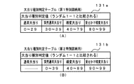
図8(A),(B)は、ROM54に記憶されている大当り種別判定テーブル131a,131bを示す説明図である。このうち、図8(A)は、遊技球が第1始動入賞口13に入賞したことにもとづく保留記憶を用いて(すなわち、第1特別図柄の変動表示が行われるとき)大当り種別を決定する場合の大当り種別判定テーブル(第1特別図柄用)131aである。また、図8(B)は、遊技球が第2始動入賞口14に入賞したことにもとづく保留記憶を用いて(すなわち、第2特別図柄の変動表示が行われるとき)大当り種別を決定する場合の大当り種別判定テーブル(第2特別図柄用)131bである。 FIGS. 8A and 8B are explanatory diagrams showing jackpot type determination tables 131a and 131b stored in the ROM 54. FIG. Of these, FIG. 8 (A) determines the jackpot type using the hold memory based on the game ball having won the first start winning opening 13 (that is, when the variable display of the first special symbol is performed). This is a jackpot type determination table (for the first special symbol) 131a. FIG. 8B shows a case where the jackpot type is determined by using the holding memory based on the fact that the game ball has won the second start winning opening 14 (that is, when the variation display of the second special symbol is performed). Is a jackpot type determination table (for the second special symbol) 131b.
大当り種別判定テーブル131a,131bは、可変表示結果を大当り図柄にする旨の判定がなされたときに、大当り種別判定用の乱数(ランダム1)にもとづいて、大当りの種別を「通常大当り」、「確変大当り」、「見せかけ確変大当り」、「突然通常大当り」のうちのいずれかに決定するために参照されるテーブルである。 The jackpot type determination tables 131a and 131b, when it is determined that the variable display result is a jackpot symbol, based on the random number (random 1) for determining the jackpot type, the jackpot type is set to “normal jackpot”, “ This table is referred to in order to determine any one of “probable big hit”, “apparent probability big hit”, and “sudden normal big hit”.
なお、この実施の形態では、図8(A),(B)に示すように、第1特別図柄の変動表示が行われる場合と第2特別図柄の変動表示が行われる場合とで、「通常大当り」および「突然通常大当り」(大当り遊技後に時短状態のみに移行される大当り)に対する割り振りの合計はともに判定値40個で同じであるが、第1特別図柄の変動表示が行われる場合には「通常大当り」および「突然通常大当り」の両方に割り振りがある(「通常大当り」に対して30個の判定値が割り当てられ、「突然通常大当り」に対して10個の判定値が割り当てられている)のに対して、第2特別図柄の変動表示が行われる場合には「突然通常大当り」にしか割り振りがない。 In this embodiment, as shown in FIGS. 8 (A) and 8 (B), “normal” is used when the first special symbol is displayed in a variable manner and when the second special symbol is displayed as a variable symbol. The total of the allocations for the “big hit” and “suddenly normal big hit” (the big hit that is shifted to only the short-time state after the big hit game) is the same with 40 judgment values, but when the variable display of the first special symbol is performed There is an allocation for both “normal jackpot” and “sudden normal jackpot” (30 judgment values are assigned to “normal jackpot” and 10 judgment values are assigned to “sudden normal jackpot”. On the other hand, when the variable display of the second special symbol is performed, only the “sudden normal big hit” is allocated.
また、この実施の形態では、図8(A)に示すように、第1特別図柄の変動表示が行われる場合には、「確変大当り」に対して40個の判定値が割り当てられ、「見せかけ確変大当り」に対して20個の判定値が割り当てられているのに対して、図8(B)に示すように、第2特別図柄の変動表示が行われる場合には、「確変大当り」に対して50個の判定値が割り当てられ、「見せかけ確変大当り」に対して10個の判定値が割り当てられている。従って、この実施の形態では、第1特別図柄の変動表示が実行される場合には、第2特別図柄の変動表示が実行される場合と比較して、「見せかけ確変大当り」に決定される割合が若干高い。 Further, in this embodiment, as shown in FIG. 8A, when the variation display of the first special symbol is performed, 40 judgment values are assigned to the “probable big hit”, While 20 decision values are assigned to “probable big hit”, as shown in FIG. 8B, when the variation display of the second special symbol is performed, “probable big hit” is set. On the other hand, 50 decision values are assigned, and 10 decision values are assigned to the “apparent probability variation big hit”. Therefore, in this embodiment, when the variable display of the first special symbol is executed, the ratio determined as the “apparent probability variation big hit” compared to the case where the variable display of the second special symbol is executed. Is slightly higher.
この実施の形態では、図8(A),(B)に示すように、大当り種別として、「通常大当り」、「確変大当り」、「見せかけ確変大当り」および「突然通常大当り」がある。 In this embodiment, as shown in FIGS. 8A and 8B, the types of jackpots include “normal jackpot”, “probable variation jackpot”, “apparent probability variation jackpot”, and “sudden normal jackpot”.
「確変大当り」とは、15ラウンドの大当り遊技状態に制御し、1ラウンドあたり29秒の長期間にわたって大入賞口を開放し、その大当り遊技状態の終了後に確変状態(高確率状態)に移行させる大当りである(この実施の形態では、確変状態に移行されるとともに時短状態にも移行される。後述するステップS167,S168参照)。そして、確変状態に移行した後、次の大当りが発生するまで確変状態が維持される(後述するステップS132参照)。 "Probability change big hit" is controlled to 15 rounds of big hit gaming state, the big winning opening is opened for a long period of 29 seconds per round, and after the big hit gaming state ends, it shifts to the probable change state (high probability state) It is a big hit (in this embodiment, it is shifted to the probability variation state and also to the time reduction state. See steps S167 and S168 described later). After the transition to the probability variation state, the probability variation state is maintained until the next big hit occurs (see step S132 described later).
また、「通常大当り」とは、15ラウンドの大当り遊技状態に制御し、1ラウンドあたり29秒の長期間にわたって大入賞口を開放し、その大当り遊技状態の終了後に確変状態に移行されず、時短状態にのみ移行される大当りである(後述するステップS169参照)。そして、時短状態に移行した後、特別図柄および演出図柄の変動表示の実行を所定回数(例えば、100回)終了するまで時短状態が維持される(後述するステップS138〜S141参照)。なお、この実施の形態では、時短状態に移行した後、所定回数の変動表示の実行を終了する前に大当りが発生した場合にも、時短状態が終了する(後述するステップS132参照)。 In addition, the “ordinary big hit” is controlled to 15 rounds of big hit gaming state, the big winning opening is opened for a long time of 29 seconds per round, and after the big hit gaming state is finished, it is not shifted to the probable change state. It is a big hit that is shifted only to the state (see step S169 described later). Then, after shifting to the time reduction state, the time reduction state is maintained until the execution of the variable symbol display of the special symbol and the effect symbol is completed a predetermined number of times (for example, 100 times) (see steps S138 to S141 described later). In this embodiment, even if a big hit occurs after the transition to the time reduction state and before the execution of the predetermined number of fluctuation displays is finished, the time reduction state ends (see step S132 described later).
また、「突然通常大当り」とは、「確変大当り」や「通常大当り」と比較して大入賞口の開放回数が2回と少なく、1回あたりの開放時間が1秒と短い大当りであり、その大当り遊技の終了後に確変状態に移行されず、時短状態にのみ移行される大当りである(後述するステップS167,S168参照)。そして、時短状態に移行した後、特別図柄および演出図柄の変動表示の実行を所定回数(例えば、100回)終了するまで時短状態が維持される(後述するステップS138〜S141参照)。なお、この実施の形態では、時短状態に移行した後、所定回数の変動表示の実行を終了する前に大当りが発生した場合にも、時短状態が終了する(後述するステップS132参照)。従って、この実施の形態では、突然通常大当りが発生すると、大入賞口に遊技球が入賞することは極めて稀であるものの、恰も突然に時短状態に移行したかのように見せることができる。 In addition, “sudden normal big hit” is a big hit where the number of opening of the big prize opening is less than 2 times compared to “probable big hit” and “normal big hit”, and the opening time per time is as short as 1 second. After the big hit game is over, it is a big hit that is not shifted to the probable change state but only the short time state (see steps S167 and S168 described later). Then, after shifting to the time reduction state, the time reduction state is maintained until the execution of the variable symbol display of the special symbol and the effect symbol is completed a predetermined number of times (for example, 100 times) (see steps S138 to S141 described later). In this embodiment, even if a big hit occurs after the transition to the time reduction state and before the execution of the predetermined number of fluctuation displays is finished, the time reduction state ends (see step S132 described later). Therefore, in this embodiment, when a normal big hit is suddenly generated, it is very rare for a game ball to win a big winning opening, but it is possible to make it appear as if the game has suddenly shifted to a short-time state.
なお、突然通常大当りは、この実施の形態で示したものにかぎらず、突然に時短状態に移行したかのように見せることができるものであれば、例えば、大入賞口の開放回数は確変大当りや通常大当りと同様15回であるが、1回あたりの開放時間のみが1秒と短い大当りであってもよい。 Note that sudden normal big hits are not limited to those shown in this embodiment, but can be displayed as if they suddenly shifted to a short-time state, for example, the number of times the big winning opening is opened is a probable big hit. Or, it is 15 times like the normal big hit, but only the opening time per time may be a short big hit of 1 second.
「見せかけ確変大当り」とは、「確変大当り」と同様に、15ラウンドの大当り遊技状態に制御し、その大当り遊技状態の終了後に確変状態(高確率状態)に移行させる大当りである(この実施の形態では、確変状態に移行されるとともに時短状態にも移行される。後述するステップS167,S168参照)。そして、確変状態に移行した後、次の大当りが発生するまで確変状態が維持される(後述するステップS132参照)。ただし、「見せかけ確変大当り」となる場合には、「確変大当り」とは異なり、最初の第1ラウンドにおいてのみ大入賞口を短い1秒間にわたって2回開放した後に29秒間の長期間にわたって大入賞口を開放し、その後、第2ラウンドから第15ラウンドまでは「確変大当り」と同様に29秒間の長期間にわたってのみ大入賞口を開放する制御を行う。 “Fake probable big hit” is a big hit that is controlled to a 15-round big hit gaming state and shifts to a probable change state (high probability state) after the big hit gaming state is completed (in this implementation). In the embodiment, the state is shifted to the probability variation state and the time reduction state (see steps S167 and S168 described later). After the transition to the probability variation state, the probability variation state is maintained until the next big hit occurs (see step S132 described later). However, in the case of “apparent odd jackpot”, unlike the “probable jackpot”, the big prize mouth is opened twice for a short one second only in the first first round and then the big prize mouth for a long period of 29 seconds. After that, from the second round to the fifteenth round, a control is performed to open the big prize opening only for a long period of 29 seconds as in “probability big hit”.
大当り種別判定テーブル131a,131bには、ランダム1の値と比較される数値であって、「通常大当り」、「確変大当り」、「見せかけ確変大当り」、「突然通常大当り」のそれぞれに対応した判定値(大当り種別判定値)が設定されている。CPU56は、ランダム1の値が大当り種別判定値のいずれかに一致した場合に、大当りの種別を、一致した大当り種別判定値に対応する種別に決定する。
The jackpot type determination tables 131a and 131b are numerical values that are compared with a random 1 value, and are determinations corresponding to “normal jackpot”, “probable variation jackpot”, “apparent probability variation jackpot”, and “sudden normal jackpot”. Value (big hit type judgment value) is set. When the value of random 1 matches any of the jackpot type determination values, the
次に、大当りにおける大入賞口の開放パターンを説明する。図9および図10は、大入賞口の開放パターンを示す説明図である。 Next, the opening pattern of the big winning opening in the big hit will be described. 9 and 10 are explanatory diagrams showing the opening pattern of the special winning opening.
まず、図9を用いて、大当り種別が通常大当りまたは確変大当りと決定された場合における大入賞口の開放パターンを説明する。この実施の形態では、大当り種別が通常大当りまたは確変大当りと決定された場合、特定ゲート200の遊技球の通過を検出してから1秒(本例では、ファンファーレ演出期間)を経過した後に、1ラウンドあたり大入賞口を29秒間開放状態に制御した後、大入賞口が1秒間閉鎖状態に制御される(ただし、大入賞口が閉鎖状態とされる1秒間はインターバル期間である)。そして、そのような開放態様のラウンドが15回繰り返されることによって、図9に示すように、大入賞口を29秒間開放状態に制御した後に1秒間閉鎖状態に制御するという動作が15回連続して繰り返される。そのため、この実施の形態では、大当り種別が通常大当りまたは確変大当りと決定された場合には、大入賞口の開放時間が29秒と長く遊技球の入賞が十分に期待できる開放動作が15回連続して実行される。
First, with reference to FIG. 9, the opening pattern of the big winning opening when the big hit type is determined as the normal big hit or the probable big hit is described. In this embodiment, when the big hit type is determined to be a normal big hit or a probable big hit, 1 second (in this example, a fanfare effect period) has elapsed since the passage of the game ball of the
また、この実施の形態では、後述するように、演出図柄の変動表示中に味方と敵のキャラクタがバトルを行うような態様のバトル演出が実行されるのであるが、変動表示を停止して大当り図柄を停止表示した後、ファンファーレ演出期間から第1ラウンドのラウンド演出期間にわたって味方のキャラクタがバトルに勝利したような態様の勝利演出が実行される。そのように、この実施の形態では、勝利演出が実行されることによって、大入賞口の開放時間が長く遊技価値が高い通常大当りや確変大当りとなることを遊技者に認識させることができる。 Further, in this embodiment, as will be described later, a battle effect is performed in such a manner that a friend and an enemy character perform a battle during the variation display of the effect symbol. After the symbols are stopped and displayed, the victory effect is executed in such a manner that the ally character wins the battle from the fanfare effect period to the round effect period of the first round. As described above, in this embodiment, by executing the victory effect, it is possible to make the player recognize that the big winning opening is long and the game value is a normal big hit or a probable big hit.
次に、図10(1)を用いて、突然通常大当りにおける大入賞口の開放パターンを説明する。この実施の形態では、突然通常大当りにもとづく大当り遊技状態に制御される場合、特定ゲート200の遊技球の通過を検出してから30秒(本例では、ファンファーレ演出期間)を経過した後に、1ラウンドあたり大入賞口を1秒間開放状態に制御した後、大入賞口が1秒間閉鎖状態に制御される(ただし、大入賞口が閉鎖状態とされる1秒間はインターバル期間である)。そして、そのような開放態様のラウンドが2回繰り返されることによって、図10(1)に示すように、大入賞口を1秒間開放状態に制御した後に1秒間閉鎖状態に制御するという動作が2回連続して繰り返される。
Next, with reference to FIG. 10 (1), the opening pattern of the big winning opening in the normal big hit will be described. In this embodiment, when suddenly controlled to the big hit game state based on the normal big hit, 30 seconds (in this example, the fanfare effect period) have elapsed since the passage of the game ball of the
また、この実施の形態では、後述するように、演出図柄の変動表示中に味方と敵のキャラクタがバトルを行うような態様のバトル演出が実行されるのであるが、変動表示を停止して大当り図柄を停止表示した後、ファンファーレ演出期間から大当り遊技中の演出期間(ラウンド期間、インターバル期間)にわたって味方のキャラクタがバトルに敗北したような態様の敗北演出が実行される。そのように、この実施の形態では、敗北演出が実行されることによって、大入賞口の開放時間が短く遊技価値が低い突然通常大当りとなることを遊技者に認識させることができる。なお、この実施の形態では、突然通常大当りとなる場合には大入賞口の開放時間が極めて短いので、敗北演出の演出期間を確保すべくファンファーレ演出期間を30秒と長くしている。 Further, in this embodiment, as will be described later, a battle effect is performed in such a manner that a friend and an enemy character perform a battle during the variation display of the effect symbol. After the symbols are stopped and displayed, the defeat effect is executed in such a manner that the ally character loses the battle over the effect period (round period, interval period) during the big hit game from the fanfare effect period. As described above, in this embodiment, by performing the defeat effect, it is possible to make the player recognize that the game is suddenly a big hit with a short opening time of the big prize opening and a low game value. In this embodiment, when the normal big hit is suddenly made, the opening time of the big prize opening is extremely short, so that the fanfare effect period is increased to 30 seconds to ensure the effect period of the defeat effect.
次に、図10(2)を用いて、見せかけ確変大当りにおける大入賞口の開放パターンを説明する。この実施の形態では、見せかけ確変大当りにもとづく大当り遊技状態に制御される場合、特定ゲート200の遊技球の通過を検出してから30秒(本例では、ファンファーレ演出期間)を経過した後に、大当り遊技の第1ラウンドを開始し、大入賞口を1秒間開放状態に制御した後に1秒間閉鎖状態とする制御を2回行い、その後、大入賞口を29秒間開放状態に制御した後、大入賞口が1秒間閉鎖状態に制御される(ただし、大入賞口が最後に閉鎖状態とされる1秒間はインターバル期間である)。そして、第2ラウンドから第15ラウンドにわたって、1ラウンドあたり大入賞口を29秒間開放状態に制御した後、大入賞口が1秒間閉鎖状態に制御される(ただし、大入賞口が閉鎖状態とされる1秒間はインターバル期間である)。そのため、この実施の形態では、大当り種別が見せかけ確変大当りと決定された場合には、恰も突然通常大当りとなるかのように見せかけておいてから、大入賞口の開放時間が29秒と長く遊技球の入賞が十分に期待できる開放動作が15回連続して実行される。
Next, with reference to FIG. 10 (2), a description will be given of the opening pattern of the big winning opening in the appearance probability variation big hit. In this embodiment, in the case of being controlled to the big hit gaming state based on the apparent probability variation big hit, the big hit is 30 seconds (in this example, the fanfare effect period) after the passage of the game ball of the
なお、この実施の形態では、見せかけ確変大当りとなる場合には、最初に突然通常大当りと同様に1秒間の短い大入賞口の開放が2回行われるのであるが、その後、通常大当りや確変大当りと同様に29秒間の長い大入賞口の開放が15回行われるのであるから、通常大当りや確変大当りと実質的に略同じ有利度合いの大当りであるということができる。 In this embodiment, in the case of a phantom probability variation jackpot, first, a short winning opening for one second is suddenly opened twice as in the case of a normal jackpot. In the same manner as above, since the long winning opening for 29 seconds is performed 15 times, it can be said that the jackpot has substantially the same advantageous degree as the normal jackpot or the probability variation jackpot.
また、この実施の形態では、後述するように、演出図柄の変動表示中に味方と敵のキャラクタがバトルを行うような態様のバトル演出が実行されるのであるが、変動表示を停止して大当り図柄を停止表示した後、ファンファーレ演出期間から第1ラウンドのラウンド演出期間中の2回の短期開放が行われる期間にわたって味方のキャラクタがバトルに敗北したような態様の敗北演出の後、味方のキャラクタが復活してバトルに勝利したような態様の復活演出が実行される。そのように、この実施の形態では、敗北演出の後に復活演出が実行されることによって、恰も大入賞口の開放時間が短く遊技価値が低い突然通常大当りとなると見せかけておいてから、大入賞口の開放時間が長く遊技価値が高い大当りとなることを遊技者に認識させることができる。なお、この実施の形態では、見せかけ確変大当りとなる場合には、突然通常大当りに見せかけるため、ファンファーレ演出期間を突然通常大当りと同様に30秒と長くしている。 Further, in this embodiment, as will be described later, a battle effect is performed in such a manner that a friend and an enemy character perform a battle during the variation display of the effect symbol. After the symbol is stopped and displayed, after the defeat effect in which the ally character has defeated the battle over the period of the two short-term releases from the fanfare effect period to the first round effect period, the ally character The revival effect is executed in a manner that makes it possible to resurrect and win the battle. As such, in this embodiment, after the defeat effect is performed, the revival effect is executed, so that it is assumed that the game is suddenly a big hit with a short opening time of the big prize opening and a low game value. It is possible to make the player recognize that the opening time of the game will be a big hit with a long game value. In this embodiment, the fanfare effect period is suddenly increased to 30 seconds as in the case of the normal big hit, since it suddenly looks like a normal big hit when it looks like a promising big hit.
なお、見せかけ確変大当りとなる場合に1秒間の短い大入賞口の開放を行わないように構成してもよい。例えば、見せかけ確変大当りとなる場合には、敗北演出の後に復活演出を実行するのみで、通常大当りや確変大当りと同様に29秒間の長い大入賞口の開放を15回行うようにしてもよい。 Note that it may be configured not to open the short prize winning opening for 1 second in the case of a masquerade probability big hit. For example, in the case of a fake probable big hit, it may be possible to perform a 29-second long winning opening just like a normal big win or a probable big hit, just by executing a revival effect after a defeat effect.
また、この実施の形態では、見せかけ確変大当りが通常大当りや確変大当りと略同じ有利度合いの大当りである場合を示しているが、見せかけ確変大当りの有利度合いが通常大当りや確変大当りよりも低くなるように構成してもよい。例えば、見せかけ確変大当りとなる場合には、1秒間の短い大入賞口の開放を2回行うようにしたり一旦敗北演出を実行するようにして、恰も突然通常大当りであるかのように見せかけた後に、29秒間の長い大入賞口の開放を15回よりも少ない回数(例えば、4回や8回)のみ実行することによって、通常大当りや確変大当りよりも有利度合いが低くなるようにしてもよい。 Further, in this embodiment, the case is shown in which the apparent probability variation big hit is a big hit with the same degree of advantage as the normal big hit or the probability variation big hit, but the advantage degree of the apparent probability variable big hit is lower than the normal big hit or the probability variable big hit. You may comprise. For example, in the case of a masquerade probable big hit, after opening the short prize winning opening for 1 second twice or once performing the defeat production, the frog suddenly pretends to be a normal jackpot. , 29 seconds of opening the big winning opening may be executed less than 15 times (for example, 4 times or 8 times), so that the degree of advantage becomes lower than the normal big hit or the probable big hit.
なお、この実施の形態では、敗北演出や復活演出の演出期間を確保するなどの目的でファンファーレ演出期間を30秒と長くする場合を示しているが、必ずしもファンファーレ演出期間を長くする必要はなく、例えば、大当り遊技開始後の第1ラウンドにおいて直ちに大入賞口を開放するのではなく30秒の閉鎖期間を経由してから大入賞口の開放を開始するようにしてもよい。そのように何らかの方法で敗北演出や復活演出の演出期間が確保されているものであればよい。また、敗北演出や復活演出の演出期間が確保されているのであれば、必ずしも30秒の期間を確保する必要はなく、20秒や40秒など他の期間が確保されていてもよい。 In addition, in this embodiment, although the case where the fanfare production period is increased to 30 seconds for the purpose of ensuring the production period of the defeat production and the resurrection production is shown, it is not always necessary to lengthen the fanfare production period. For example, instead of immediately opening the big prize opening in the first round after the start of the big hit game, the opening of the big prize opening may be started after a closing period of 30 seconds. Any method may be used as long as the production period of the defeat production or the revival production is ensured by some method. Further, as long as the defeat production and the revival production period are secured, it is not always necessary to secure the 30-second period, and other periods such as 20 seconds or 40 seconds may be secured.
また、この実施の形態では、第2特別図柄の変動表示を優先実行するように構成しているのであるから、一度大当りが発生し遊技状態が確変状態に制御される(この場合、時短状態にも制御される)と、殆ど第2特別図柄の変動表示が連続して実行されることになる。そして、確変状態中に第2特別図柄の変動表示結果が確変大当りまたは見せかけ確変大当りとなる限り、勝利演出または復活演出が実行され確変状態が継続することになる。そして、既に説明したように、この実施の形態では、第2特別図柄の変動表示が実行される場合には通常大当りに対する割り振りがなく、確変大当りと見せかけ確変大当り以外には突然通常大当りにしか割り振りがないのであるから(図8(B)参照)、確変状態中である場合には突然通常大当りとなった場合に敗北演出が実行され確変状態が終了することになる。 Further, in this embodiment, since the variation display of the second special symbol is preferentially executed, a big hit occurs once and the gaming state is controlled to the probability variation state (in this case, the time reduction state is set). Is also controlled), the variation display of the second special symbol is almost continuously executed. Then, as long as the fluctuation display result of the second special symbol becomes a probability variation big hit or a fake probability variation big hit during the probability variation state, the victory effect or the resurrection effect is executed and the probability variation state is continued. As already described, in this embodiment, when the variation display of the second special symbol is executed, there is no allocation to the normal big hit, and only the normal big hit is suddenly allocated except for the probable big hit and the apparent variable big hit. Since there is no (see FIG. 8 (B)), when the probability change state is in effect, the defeat effect is executed and the probability change state ends when the normal big hit suddenly occurs.
図11および図12は、遊技制御用マイクロコンピュータ560が送信する演出制御コマンドの内容の一例を示す説明図である。図11および図12に示す例において、コマンド80XX(H)は、特別図柄の可変表示に対応して演出表示装置9において可変表示される演出図柄の変動パターンを指定する演出制御コマンド(変動パターンコマンド)である(それぞれ変動パターンXXに対応)。つまり、使用されうる変動パターンのそれぞれに対して一意な番号を付した場合に、その番号で特定される変動パターンのそれぞれに対応する変動パターンコマンドがある。なお、「(H)」は16進数であることを示す。また、変動パターンを指定する演出制御コマンドは、変動開始を指定するためのコマンドでもある。従って、演出制御用マイクロコンピュータ100は、コマンド80XX(H)を受信すると、演出表示装置9において演出図柄の可変表示を開始するように制御する。
FIG. 11 and FIG. 12 are explanatory diagrams showing an example of the contents of the effect control command transmitted by the
コマンド8C01(H)〜8C05(H)は、大当りとするか否か、および大当り種別を示す演出制御コマンドである。演出制御用マイクロコンピュータ100は、コマンド8C01(H)〜8C05(H)の受信に応じて演出図柄の表示結果を決定するので、コマンド8C01(H)〜8C05(H)を表示結果指定コマンドという。
Commands 8C01 (H) to 8C05 (H) are effect control commands indicating whether or not to make a big hit and the type of big hit. The
コマンド8D01(H)は、第1特別図柄の可変表示(変動)を開始することを示す演出制御コマンド(第1図柄変動指定コマンド)である。コマンド8D02(H)は、第2特別図柄の可変表示(変動)を開始することを示す演出制御コマンド(第2図柄変動指定コマンド)である。第1図柄変動指定コマンドと第2図柄変動指定コマンドとを特別図柄特定コマンド(または図柄変動指定コマンド)と総称することがある。なお、第1特別図柄の可変表示を開始するのか第2特別図柄の可変表示を開始するのかを示す情報を、変動パターンコマンドに含めるようにしてもよい。 Command 8D01 (H) is an effect control command (first symbol variation designation command) indicating that variable display (variation) of the first special symbol is started. Command 8D02 (H) is an effect control command (second symbol variation designation command) indicating that variable display (variation) of the second special symbol is started. The first symbol variation designation command and the second symbol variation designation command may be collectively referred to as a special symbol specifying command (or symbol variation designation command). Note that information indicating whether to start variable display of the first special symbol or variable display of the second special symbol may be included in the variation pattern command.
コマンド8F00(H)は、第4図柄の可変表示(変動)を終了して表示結果(停止図柄)を導出表示することを示す演出制御コマンド(図柄確定指定コマンド)である。演出制御用マイクロコンピュータ100は、図柄確定指定コマンドを受信すると、第4図柄の可変表示(変動)を終了して表示結果を導出表示する。
Command 8F00 (H) is an effect control command (symbol confirmation designation command) indicating that the variable display (fluctuation) of the fourth symbol is terminated and the display result (stop symbol) is derived and displayed. When receiving the symbol confirmation designation command, the
コマンド9000(H)は、遊技機に対する電力供給が開始されたときに送信される演出制御コマンド(初期化指定コマンド:電源投入指定コマンド)である。具体的には、コマンド9000(H)は、遊技機への電力供給開始時に初期化処理が実行された場合に送信される(ステップS10〜S14参照)。 Command 9000 (H) is an effect control command (initialization designation command: power-on designation command) transmitted when power supply to the gaming machine is started. Specifically, the command 9000 (H) is transmitted when the initialization process is executed at the start of power supply to the gaming machine (see steps S10 to S14).
コマンド9200(H)は、遊技機に対する電力供給が再開されたときに送信される演出制御コマンド(停電復旧指定コマンド)である。具体的には、コマンド9200(H)は、遊技機への電力供給開始時に停電復旧処理が実行された場合に送信される(ステップS41〜S44参照)。 Command 9200 (H) is an effect control command (power failure recovery designation command) transmitted when power supply to the gaming machine is resumed. Specifically, command 9200 (H) is transmitted when a power failure recovery process is executed at the start of power supply to the gaming machine (see steps S41 to S44).
コマンド9F00(H)は、客待ちデモンストレーションを指定する演出制御コマンド(客待ちデモ指定コマンド)である。 Command 9F00 (H) is an effect control command (customer waiting demonstration designation command) for designating a customer waiting demonstration.
コマンドA001〜A004(H)は、ファンファーレ画面を表示すること、すなわち大当り遊技の開始を指定する演出制御コマンド(大当り開始指定コマンド:ファンファーレ指定コマンド)である。この実施の形態では、大当りの種類に応じて、大当り開始1指定コマンド、大当り開始2指定コマンド、大当り開始3指定コマンド、または突然通常大当り開始指定コマンドが用いられる。具体的には、「通常大当り」である場合には大当り開始1指定コマンド(A001(H))が用いられ、「確変大当り」である場合には大当り開始2指定コマンド(A002(H))が用いられ、「見せかけ確変大当り」である場合には大当り開始3指定コマンド(A003(H))が用いられ、「突然通常大当り」である場合には突然通常大当り開始指定コマンド(A004(H))が用いられる。
The commands A001 to A004 (H) are effect control commands for displaying the fanfare screen, that is, designating the start of the big hit game (big hit start designation command: fanfare designation command). In this embodiment, depending on the type of jackpot, a
コマンドA1XX(H)は、XXで示す回数目(ラウンド)の大入賞口開放中の表示を示す演出制御コマンド(大入賞口開放中指定コマンド)である。なお、大入賞口開放中指定コマンドは、内部制御上のラウンド数(見た目上のラウンド数ではない)を示す値がEXTデータにセットされて演出制御用マイクロコンピュータ100に送信される。従って、演出制御用マイクロコンピュータ100は、大入賞口開放中指定コマンドのEXTデータを確認すれば、大当り遊技中の何ラウンドを開始する場合であるかを認識することができる。例えば、EXTデータとして「01(H)」がセットされていれば、大当り遊技のラウンド1の開始であることを認識することができ、EXTデータとして「07(H)」がセットされていれば、大当り遊技のラウンド7の開始であることを認識することができる。
The command A1XX (H) is an effect control command (special command during opening of a big winning opening) indicating a display during the opening of the big winning opening for the number of times (round) indicated by XX. Note that the value indicating the number of rounds in internal control (not the apparent number of rounds) is set in the EXT data and transmitted to the
コマンドA2XX(H)は、XXで示す回数目(ラウンド)の大入賞口閉鎖を示す演出制御コマンド(大入賞口開放後指定コマンド)である。なお、大入賞口開放後指定コマンドは、内部制御上のラウンド数(見た目上のラウンド数ではない)を示す値がEXTデータにセットされて演出制御用マイクロコンピュータ100に送信される。従って、演出制御用マイクロコンピュータ100は、大入賞口開放後指定コマンドのEXTデータを確認すれば、大当り遊技中の何ラウンドを終了する場合であるかを認識することができる。例えば、EXTデータとして「01(H)」がセットされていれば、大当り遊技のラウンド1の終了であることを認識することができ、EXTデータとして「07(H)」がセットされていれば、大当り遊技のラウンド7の終了であることを認識することができる。
The command A2XX (H) is an effect control command (designation command after opening the big winning opening) indicating the closing of the big winning opening for the number of times (round) indicated by XX. Note that the value indicating the number of rounds in internal control (not the apparent number of rounds) is set in the EXT data and transmitted to the
コマンドA301(H)〜A304(H)は、大当り終了画面を表示すること、すなわち大当り遊技の終了を指定する演出制御コマンド(大当り終了指定コマンド:エンディング指定コマンド)である。この実施の形態では、大当りの種類に応じて、大当り終了1指定コマンド、大当り終了2指定コマンド、大当り終了3指定コマンド、または突然通常大当り終了指定コマンドが用いられる。具体的には、「通常大当り」である場合には大当り終了1指定コマンド(A301(H))が用いられ、「確変大当り」である場合には大当り終了2指定コマンド(A302(H))が用いられ、「見せかけ確変大当り」である場合には大当り終了3指定コマンド(A303(H))が用いられ、「突然通常大当り」である場合には突然通常大当り終了指定コマンド(A304(H))が用いられる。
The commands A301 (H) to A304 (H) are effect control commands for displaying a jackpot end screen, that is, designating the end of the jackpot game (a jackpot end designation command: an ending designation command). In this embodiment, depending on the type of jackpot, a
コマンドB000(H)は、遊技状態が通常状態であるときの背景表示を指定する演出制御コマンド(通常状態背景指定コマンド)である。コマンドB001(H)は、遊技状態が時短状態(確変状態を含まない)であるときの背景表示を指定する演出制御コマンド(時短状態背景指定コマンド)である。コマンドB002(H)は、遊技状態が確変状態であるときの背景表示を指定する演出制御コマンド(確変状態背景指定コマンド)である。 Command B000 (H) is an effect control command (normal state background designation command) for designating background display when the gaming state is the normal state. Command B001 (H) is an effect control command (time-short state background designation command) for designating a background display when the gaming state is the time-short state (not including the probability variation state). Command B002 (H) is an effect control command (probability change state background designation command) for designating a background display when the gaming state is in the probability change state.
コマンドC000(H)は、第1保留記憶数が1増加したことを指定する演出制御コマンド(第1保留記憶数加算指定コマンド)である。コマンドC100(H)は、第2保留記憶数が1増加したことを指定する演出制御コマンド(第2保留記憶数加算指定コマンド)である。コマンドC200(H)は、第1保留記憶数が1減少したことを指定する演出制御コマンド(第1保留記憶数減算指定コマンド)である。コマンドC300(H)は、第2保留記憶数が1減少したことを指定する演出制御コマンド(第2保留記憶数減算指定コマンド)である。 Command C000 (H) is an effect control command (first reserved memory number addition designation command) that specifies that the first reserved memory number has increased by one. Command C100 (H) is an effect control command (second reserved memory number addition designation command) that specifies that the second reserved memory number has increased by one. Command C200 (H) is an effect control command (first reserved memory number subtraction designation command) that specifies that the first reserved memory number has decreased by one. Command C300 (H) is an effect control command (second reserved memory number subtraction designation command) that specifies that the second reserved memory number has decreased by one.
なお、この実施の形態では、第1保留記憶数と第2保留記憶数とについて、それぞれ保留記憶数が増加または減少したことを示す演出制御コマンドを送信する場合を示しているが、保留記憶数そのものを指定する演出制御コマンドを送信するようにしてもよい。この場合、例えば、第1始動入賞口13と第2始動入賞口14とのいずれに始動入賞したかを指定する演出制御コマンドを送信するとともに、保留記憶数を指定する保留記憶数指定コマンドとして第1保留記憶数と第2保留記憶数とで共通の演出制御コマンドを送信するようにしてもよい。
In this embodiment, a case is shown in which an effect control command indicating that the number of reserved memories is increased or decreased is transmitted for each of the first reserved memory number and the second reserved memory number. You may make it transmit the production control command which designates itself. In this case, for example, an effect control command for designating which one of the first
また、例えば、第1保留記憶数を指定する場合と第2保留記憶数を指定する場合とで別々の演出制御コマンド(保留記憶数指定コマンド)を送信するようにしてもよい。この場合、例えば、保留記憶数指定コマンドとして、MODEデータとして第1保留記憶数または第2保留記憶数を特定可能な値(例えば、第1保留記憶数を指定する場合には「C0(H)」、第2保留記憶数を指定する場合には「C1(H)」)を含むとともに、EXTデータとして保留記憶数の値を設定した演出制御コマンドを送信するようにしてもよい。 Further, for example, separate presentation control commands (holding memory number designation commands) may be transmitted when the first holding memory number is designated and when the second holding memory number is designated. In this case, for example, as a reserved memory number designation command, a value that can specify the first reserved memory number or the second reserved memory number as MODE data (for example, “C0 (H) when designating the first reserved memory number) ”And“ C1 (H) ”in the case of designating the second reserved memory number), an effect control command in which the value of the reserved memory number is set as EXT data may be transmitted.
また、例えば、同じ第1保留記憶数を指定する場合であれば、MODEデータを共通として、EXTデータを異ならせることによって、第1保留記憶数の加算または減算を指定した演出制御コマンドを送信するようにしてもよい。例えば、共通のMODEデータ「C0(H)」を用い、第1保留記憶数の減算を指定する場合にはコマンドC000(H)を送信するようにし、第1保留記憶数の加算を指定する場合にはコマンドC001(H)を送信するようにしてもよい。さらに、第2保留記憶数を指定する場合にはMODEデータを異ならせて、第2保留記憶数の減算を指定する場合にはコマンドC100(H)を送信するようにし、第2保留記憶数の加算を指定する場合にはコマンドC101(H)を送信するようにしてもよい。 Also, for example, if the same first reserved memory number is specified, an effect control command specifying the addition or subtraction of the first reserved memory number is transmitted by making the MODE data common and different EXT data. You may do it. For example, when the common MODE data “C0 (H)” is used and the subtraction of the first reserved memory number is designated, the command C000 (H) is transmitted, and the addition of the first reserved memory number is designated. The command C001 (H) may be transmitted. Further, when specifying the second reserved memory number, the MODE data is made different, and when specifying the subtraction of the second reserved memory number, the command C100 (H) is transmitted, and the second reserved memory number is determined. When adding is designated, the command C101 (H) may be transmitted.
演出制御基板80に搭載されている演出制御用マイクロコンピュータ100(具体的には、演出制御用CPU101)は、主基板31に搭載されている遊技制御用マイクロコンピュータ560から上述した演出制御コマンドを受信すると、図11および図12に示された内容に応じて演出表示装置9の表示状態を変更したり、ランプの表示状態を変更したり、音声出力基板70に対して音番号データを出力したりする。
The effect control microcomputer 100 (specifically, the effect control CPU 101) mounted on the
例えば、遊技制御用マイクロコンピュータ560は、始動入賞があり第1特別図柄表示器8aまたは第2特別図柄表示器8bにおいて特別図柄の可変表示が開始される度に、演出図柄の変動パターンを指定する変動パターンコマンドおよび表示結果指定コマンドを演出制御用マイクロコンピュータ100に送信する。
For example, the
この実施の形態では、演出制御コマンドは2バイト構成であり、1バイト目はMODE(コマンドの分類)を表し、2バイト目はEXT(コマンドの種類)を表す。MODEデータの先頭ビット(ビット7)は必ず「1」に設定され、EXTデータの先頭ビット(ビット7)は必ず「0」に設定される。なお、そのようなコマンド形態は一例であって他のコマンド形態を用いてもよい。例えば、1バイトや3バイト以上で構成される制御コマンドを用いてもよい。 In this embodiment, the effect control command has a 2-byte structure, the first byte represents MODE (command classification), and the second byte represents EXT (command type). The first bit (bit 7) of the MODE data is always set to “1”, and the first bit (bit 7) of the EXT data is always set to “0”. Note that such a command form is an example, and other command forms may be used. For example, a control command composed of 1 byte or 3 bytes or more may be used.
なお、演出制御コマンドの送出方式として、演出制御信号CD0〜CD7の8本のパラレル信号線で1バイトずつ主基板31から中継基板77を介して演出制御基板80に演出制御コマンドデータを出力し、演出制御コマンドデータの他に、演出制御コマンドデータの取込を指示するパルス状(矩形波状)の取込信号(演出制御INT信号)を出力する方式を用いる。演出制御コマンドの8ビットの演出制御コマンドデータは、演出制御INT信号に同期して出力される。演出制御基板80に搭載されている演出制御用マイクロコンピュータ100は、演出制御INT信号が立ち上がったことを検知して、割込処理によって1バイトのデータの取り込み処理を開始する。
In addition, as the transmission method of the effect control command, the effect control command data is output from the main board 31 to the
図11および図12に示す例では、変動パターンコマンドおよび表示結果指定コマンドを、第1特別図柄表示器8aでの第1特別図柄の変動に対応した演出図柄の可変表示(変動)と第2特別図柄表示器8bでの第2特別図柄の変動に対応した演出図柄の可変表示(変動)とで共通に使用でき、第1特別図柄および第2特別図柄の可変表示に伴って演出を行う演出表示装置9などの演出用部品を制御する際に、遊技制御用マイクロコンピュータ560から演出制御用マイクロコンピュータ100に送信されるコマンドの種類を増大させないようにすることができる。
In the example shown in FIG. 11 and FIG. 12, the variable pattern command and the display result designation command are displayed as variable display (variation) of the effect symbol corresponding to the variation of the first special symbol on the first
図13は、主基板31に搭載される遊技制御用マイクロコンピュータ560(具体的には、CPU56)が実行する特別図柄プロセス処理(ステップS28)のプログラムの一例を示すフローチャートである。上述したように、特別図柄プロセス処理では第1特別図柄表示器8aまたは第2特別図柄表示器8bおよび大入賞口を制御するための処理が実行される。特別図柄プロセス処理において、CPU56は、第1始動入賞口13に遊技球が入賞したことを検出するための第1始動口スイッチ13a、または第2始動入賞口14に遊技球が入賞したことを検出するための第2始動口スイッチ14aがオンしていたら、すなわち、第1始動入賞口13への始動入賞または第2始動入賞口14への始動入賞が発生していたら、始動口スイッチ通過処理を実行する(ステップS321,S322)。そして、ステップS300〜S307のうちのいずれかの処理を行う。第1始動入賞口スイッチ13aまたは第2始動口スイッチ14aがオンしていなければ、内部状態に応じて、ステップS300〜S307のうちのいずれかの処理を行う。
FIG. 13 is a flowchart showing an example of a special symbol process (step S28) program executed by the game control microcomputer 560 (specifically, the CPU 56) mounted on the main board 31. As described above, in the special symbol process, a process for controlling the first
ステップS300〜S307の処理は、以下のような処理である。 The processes in steps S300 to S307 are as follows.
特別図柄通常処理(ステップS300):特別図柄プロセスフラグの値が0であるときに実行される。遊技制御用マイクロコンピュータ560は、特別図柄の可変表示が開始できる状態になると、保留記憶数バッファに記憶される数値データの記憶数(合算保留記憶数)を確認する。保留記憶数バッファに記憶される数値データの記憶数は合算保留記憶数カウンタのカウント値により確認できる。また、合算保留記憶数カウンタのカウント値が0でなければ、第1特別図柄または第2特別図柄の可変表示の表示結果を大当りとするか否かを決定する。大当りとする場合には大当りフラグをセットする。そして、内部状態(特別図柄プロセスフラグ)をステップS301に応じた値(この例では1)に更新する。なお、大当りフラグは、大当り遊技が終了するときにリセットされる。
Special symbol normal processing (step S300): Executed when the value of the special symbol process flag is zero. When the
変動パターン設定処理(ステップS301):特別図柄プロセスフラグの値が1であるときに実行される。また、変動パターンを決定し、その変動パターンにおける変動時間(可変表示時間:可変表示を開始してから表示結果を導出表示(停止表示)するまでの時間)を特別図柄の可変表示の変動時間とすることに決定する。また、特別図柄の変動時間を計測する変動時間タイマをスタートさせる。そして、内部状態(特別図柄プロセスフラグ)をステップS302に対応した値(この例では2)に更新する。 Fluctuation pattern setting process (step S301): This process is executed when the value of the special symbol process flag is 1. Also, the variation pattern is determined, and the variation time in the variation pattern (variable display time: the time from the start of variable display until the display result is derived and displayed (stop display)) is defined as the variation display variation time of the special symbol. Decide to do. Also, a variable time timer for measuring the special symbol variable time is started. Then, the internal state (special symbol process flag) is updated to a value (2 in this example) corresponding to step S302.
表示結果指定コマンド送信処理(ステップS302):特別図柄プロセスフラグの値が2であるときに実行される。演出制御用マイクロコンピュータ100に、表示結果指定コマンドを送信する制御を行う。そして、内部状態(特別図柄プロセスフラグ)をステップS303に対応した値(この例では3)に更新する。
Display result designation command transmission process (step S302): This process is executed when the value of the special symbol process flag is 2. Control for transmitting a display result designation command to the
特別図柄変動中処理(ステップS303):特別図柄プロセスフラグの値が3であるときに実行される。変動パターン設定処理で選択された変動パターンの変動時間が経過(ステップS301でセットされる変動時間タイマがタイムアウトすなわち変動時間タイマの値が0になる)すると、演出制御用マイクロコンピュータ100に、図柄確定指定コマンドを送信する制御を行い、内部状態(特別図柄プロセスフラグ)をステップS304に対応した値(この例では4)に更新する。なお、演出制御用マイクロコンピュータ100は、遊技制御用マイクロコンピュータ560が送信する図柄確定指定コマンドを受信すると演出表示装置9において第4図柄が停止されるように制御する。
Special symbol changing process (step S303): This process is executed when the value of the special symbol process flag is 3. When the variation time of the variation pattern selected in the variation pattern setting process elapses (the variation time timer set in step S301 times out, that is, the variation time timer value becomes 0), the
特別図柄停止処理(ステップS304):特別図柄プロセスフラグの値が4であるときに実行される。大当りフラグがセットされている場合に、特定ゲートスイッチ200aがオンしたことを条件として、内部状態(特別図柄プロセスフラグ)をステップS305に対応した値(この例では5)に更新する。大当りフラグがセットされていない場合には、内部状態(特別図柄プロセスフラグ)をステップS300に対応した値(この例では0)に更新する。なお、この実施の形態では、特別図柄プロセスフラグの値が4となったことにもとづいて、後述するように、特別図柄表示制御処理において特別図柄の停止図柄を停止表示するための特別図柄表示制御データが特別図柄表示制御データ設定用の出力バッファに設定され(図25参照)、ステップS22の表示制御処理において出力バッファの設定内容に応じて実際に特別図柄の停止図柄が停止表示される。
Special symbol stop process (step S304): executed when the value of the special symbol process flag is 4. When the big hit flag is set, the internal state (special symbol process flag) is updated to a value corresponding to step S305 (5 in this example) on condition that the
大入賞口開放前処理(ステップS305):特別図柄プロセスフラグの値が5であるときに実行される。大入賞口開放前処理では、大入賞口を開放する制御を行う。具体的には、カウンタ(例えば、大入賞口に入った遊技球数をカウントするカウンタ)などを初期化するとともに、ソレノイド21を駆動して大入賞口を開放状態にする。また、タイマによって大入賞口開放中処理の実行時間を設定し、内部状態(特別図柄プロセスフラグ)をステップS306に対応した値(この例では6)に更新する。なお、大入賞口開放前処理は各ラウンド毎に実行されるが、第1ラウンドを開始する場合には、大入賞口開放前処理は大当り遊技を開始する処理でもある。
Preliminary winning opening opening process (step S305): This is executed when the value of the special symbol process flag is 5. In the pre-opening process for the big prize opening, control for opening the big prize opening is performed. Specifically, a counter (for example, a counter that counts the number of game balls that have entered the big prize opening) is initialized and the
大入賞口開放中処理(ステップS306):特別図柄プロセスフラグの値が6であるときに実行される。大当り遊技状態中のラウンド表示の演出制御コマンドを演出制御用マイクロコンピュータ100に送信する制御や大入賞口の開閉制御の処理等を行う。ラウンド中の全ての大入賞口の開放を終了し、かつ、まだ残りラウンドがある場合には、内部状態(特別図柄プロセスフラグ)をステップS305に対応した値(この例では5)に更新する。また、全てのラウンドを終えた場合には、内部状態(特別図柄プロセスフラグ)をステップS307に対応した値(この例では7)に更新する。
Large winning opening opening process (step S306): This process is executed when the value of the special symbol process flag is 6. A control for transmitting a presentation control command for a round display during the big hit gaming state to the
大当り終了処理(ステップS307):特別図柄プロセスフラグの値が7であるときに実行される。大当り遊技状態が終了したことを遊技者に報知する表示制御を演出制御用マイクロコンピュータ100に行わせるための制御を行う。また、遊技状態を示すフラグ(例えば、確変フラグや時短フラグ)をセットする処理を行う。そして、内部状態(特別図柄プロセスフラグ)をステップS300に対応した値(この例では0)に更新する。
Big hit end process (step S307): executed when the value of the special symbol process flag is 7. Control is performed to cause the
図14は、ステップS322の始動口スイッチ通過処理を示すフローチャートである。始動口スイッチ通過処理において、CPU56は、まず、第1始動口スイッチ13aがオン状態であるか否かを確認する(ステップS211)。第1始動口スイッチ13aがオン状態でなければ、ステップS217に移行する。第1始動口スイッチ13aがオン状態であれば、CPU56は、第1保留記憶数が上限値に達しているか否か(具体的には、第1保留記憶数をカウントするための第1保留記憶数カウンタの値が4でるか否か)を確認する(ステップS212)。第1保留記憶数が上限値に達していれば、ステップS217に移行する。
FIG. 14 is a flowchart showing the start port switch passing process in step S322. In the start port switch passing process, the
第1保留記憶数が上限値に達していなければ、CPU56は、第1保留記憶数カウンタの値を1増やす(ステップS213)とともに、合算保留記憶数をカウントするための合算保留記憶数カウンタの値を1増やす(ステップS214)。次いで、CPU56は、乱数回路503やソフトウェア乱数を生成するためのカウンタから値を抽出し、それらを、第1保留記憶バッファ(図15参照)における保存領域に格納する処理を実行する(ステップS215)。なお、ステップS215の処理では、ハードウェア乱数であるランダムR(大当り判定用乱数)や、ソフトウェア乱数である大当り種別判定用乱数(ランダム1)、変動パターン種別判定用乱数(ランダム2)および変動パターン判定用乱数(ランダム3)が抽出され、保存領域に格納される。なお、変動パターン種別判定用乱数(ランダム2)や変動パターン判定用乱数(ランダム3)を始動口スイッチ通過処理(始動入賞時)において抽出して保存領域にあらかじめ格納しておくのではなく、第1特別図柄の変動開始時に抽出するようにしてもよい。例えば、遊技制御用マイクロコンピュータ560は、後述する変動パターン設定処理において、変動パターン種別判定用乱数(ランダム2)を生成するための変動パターン種別判定用乱数カウンタから値を直接抽出したり、変動パターン判定用乱数(ランダム3)を生成するための変動パターン判定用乱数カウンタから値を直接抽出したりするようにしてもよい。
If the first reserved memory number has not reached the upper limit value, the
図15は、保留記憶に対応する乱数等を保存する領域(保留バッファ)の構成例を示す説明図である。図15に示すように、第1保留記憶バッファには、第1保留記憶数の上限値(この例では4)に対応した保存領域が確保されている。また、第2保留記憶バッファには、第2保留記憶数の上限値(この例では4)に対応した保存領域が確保されている。この実施の形態では、第1保留記憶バッファおよび第2保留記憶バッファには、ハードウェア乱数であるランダムR(大当り判定用乱数)や、ソフトウェア乱数である大当り種別判定用乱数(ランダム1)、変動パターン種別判定用乱数(ランダム2)および変動パターン判定用乱数(ランダム3)が記憶される。なお、第1保留記憶バッファおよび第2保留記憶バッファは、RAM55に形成されている。
FIG. 15 is an explanatory diagram showing a configuration example of an area (hold buffer) for storing random numbers and the like corresponding to the hold memory. As shown in FIG. 15, a storage area corresponding to the upper limit value (4 in this example) of the first reserved storage number is secured in the first reserved storage buffer. In addition, a storage area corresponding to the upper limit value of the second reserved storage number (4 in this example) is secured in the second reserved storage buffer. In this embodiment, the first reserved storage buffer and the second reserved storage buffer include a random R (big hit determination random number) that is a hardware random number, a big hit type determination random number (random 1) that is a software random number, a variation A random number for pattern type determination (random 2) and a random number for variation pattern determination (random 3) are stored. The first reserved storage buffer and the second reserved storage buffer are formed in the
そして、CPU56は、第1保留記憶数加算指定コマンドを演出制御用マイクロコンピュータ100に送信する制御を行う(ステップS216)。
Then, the
次いで、CPU56は、第2始動口スイッチ14aがオン状態であるか否かを確認する(ステップS217)。第2始動口スイッチ14aがオン状態でなければ、そのまま処理を終了する。第2始動口スイッチ14aがオン状態であれば、CPU56は、第2保留記憶数が上限値に達しているか否か(具体的には、第2保留記憶数をカウントするための第2保留記憶数カウンタの値が4でるか否か)を確認する(ステップS218)。第2保留記憶数が上限値に達していれば、そのまま処理を終了する。
Next, the
第2保留記憶数が上限値に達していなければ、CPU56は、第2保留記憶数カウンタの値を1増やす(ステップS219)とともに、合算保留記憶数をカウントするための合算保留記憶数カウンタの値を1増やす(ステップS220)。次いで、CPU56は、乱数回路503やソフトウェア乱数を生成するためのカウンタから値を抽出し、それらを、第2保留記憶バッファ(図15参照)における保存領域に格納する処理を実行する(ステップS221)。なお、ステップS221の処理では、ハードウェア乱数であるランダムR(大当り判定用乱数)や、ソフトウェア乱数である大当り種別判定用乱数(ランダム1)、変動パターン種別判定用乱数(ランダム2)および変動パターン判定用乱数(ランダム3)が抽出され、保存領域に格納される。なお、変動パターン判定用乱数(ランダム3)を始動口スイッチ通過処理(始動入賞時)において抽出して保存領域にあらかじめ格納しておくのではなく、第2特別図柄の変動開始時に抽出するようにしてもよい。例えば、遊技制御用マイクロコンピュータ560は、後述する変動パターン設定処理において、変動パターン判定用乱数(ランダム3)を生成するための変動パターン判定用乱数カウンタから値を直接抽出するようにしてもよい。
If the second reserved memory number has not reached the upper limit value, the
そして、CPU56は、第2保留記憶数加算指定コマンドを演出制御用マイクロコンピュータ100に送信する制御を行う(ステップS222)。
Then, the
図16および図17は、特別図柄プロセス処理における特別図柄通常処理(ステップS300)を示すフローチャートである。特別図柄通常処理において、CPU56は、合算保留記憶数の値を確認する(ステップS51)。具体的には、合算保留記憶数カウンタのカウント値を確認する。合算保留記憶数が0であれば、まだ客待ちデモ指定コマンドを送信していなければ、演出制御用マイクロコンピュータ100に対して客待ちデモ指定コマンドを送信する制御を行い(ステップS51A)、処理を終了する。なお、例えば、CPU56は、ステップS51Aで客待ちデモ指定コマンドを送信すると、客待ちデモ指定コマンドを送信したことを示す客待ちデモ指定コマンド送信済フラグをセットする。そして、客待ちデモ指定コマンドを送信した後に次回のタイマ割込以降の特別図柄通常処理を実行する場合には、客待ちデモ指定コマンド送信済フラグがセットされていることにもとづいて重ねて客待ちデモ指定コマンドを送信しないように制御すればよい。また、この場合、客待ちデモ指定コマンド送信済フラグは、次回の特別図柄の変動表示が開始されるときにリセットされるようにすればよい。
16 and 17 are flowcharts showing the special symbol normal process (step S300) in the special symbol process. In the special symbol normal process, the
合算保留記憶数が0でなければ、CPU56は、第2保留記憶数が0であるか否かを確認する(ステップS52)。具体的には、第2保留記憶数カウンタの値が0であるか否かを確認する。第2保留記憶数が0でなければ、CPU56は、特別図柄ポインタ(第1特別図柄について特別図柄プロセス処理を行っているのか第2特別図柄について特別図柄プロセス処理を行っているのかを示すフラグ)に「第2」を示すデータを設定する(ステップS53)。第2保留記憶数が0であれば(すなわち、第1保留記憶数のみが溜まっている場合)には、CPU66は、特別図柄ポインタに「第1」を示すデータを設定する(ステップS54)。
If the total reserved memory number is not 0, the
この実施の形態では、ステップS52〜S54の処理が実行されることによって、第1特別図柄の変動表示に対して、第2特別図柄の変動表示が優先して実行される。言い換えれば、第2特別図柄の変動表示を開始させるための第2の開始条件が第1特別図柄の変動表示を開始させるための第1の開始条件に優先して成立するように制御される。 In this embodiment, by executing the processing of steps S52 to S54, the variation display of the second special symbol is executed with priority over the variation display of the first special symbol. In other words, control is performed so that the second start condition for starting the variable display of the second special symbol is established in preference to the first start condition for starting the variable display of the first special symbol.
次いで、CPU56は、RAM55において、特別図柄ポインタが示す方の保留記憶数=1に対応する保存領域に格納されている各乱数値を読み出してRAM55の乱数バッファ領域に格納する(ステップS55)。具体的には、CPU56は、特別図柄ポインタが「第1」を示している場合には、第1保留記憶数バッファにおける第1保留記憶数=1に対応する保存領域に格納されている各乱数値を読み出してRAM55の乱数バッファ領域に格納する。また、CPU56は、特別図柄ポインタが「第2」を示している場合には、第2保留記憶数バッファにおける第2保留記憶数=1に対応する保存領域に格納されている各乱数値を読み出してRAM55の乱数バッファ領域に格納する。
Next, the
そして、CPU56は、特別図柄ポインタが示す方の保留記憶数カウンタのカウント値を1減算し、かつ、各保存領域の内容をシフトする(ステップS56)。具体的には、CPU56は、特別図柄ポインタが「第1」を示している場合には、第1保留記憶数カウンタのカウント値を1減算し、かつ、第1保留記憶数バッファにおける各保存領域の内容をシフトする。また、特別図柄ポインタが「第2」を示している場合に、第2保留記憶数カウンタのカウント値を1減算し、かつ、第2保留記憶数バッファにおける各保存領域の内容をシフトする。
Then, the
すなわち、CPU56は、特別図柄ポインタが「第1」を示している場合に、RAM55の第1保留記憶数バッファにおいて第1保留記憶数=n(n=2,3,4)に対応する保存領域に格納されている各乱数値を、第1保留記憶数=n−1に対応する保存領域に格納する。また、特別図柄ポインタが「第2」を示す場合に、RAM55の第2保留記憶数バッファにおいて第2保留記憶数=n(n=2,3,4)に対応する保存領域に格納されている各乱数値を、第2保留記憶数=n−1に対応する保存領域に格納する。
That is, when the special symbol pointer indicates “first”, the
よって、各第1保留記憶数(または、各第2保留記憶数)に対応するそれぞれの保存領域に格納されている各乱数値が抽出された順番は、常に、第1保留記憶数(または、第2保留記憶数)=1,2,3,4の順番と一致するようになっている。 Therefore, the order in which each random value stored in each storage area corresponding to each first reserved memory number (or each second reserved memory number) is extracted is always the first reserved memory number (or (Second reserved storage number) = 1, 2, 3, 4 in order.
そして、CPU56は、合算保留記憶数の値を1減らす。すなわち、合算保留記憶数カウンタのカウント値を1減算する(ステップS58)。なお、CPU56は、カウント値が1減算される前の合算保留記憶数カウンタの値をRAM55の所定の領域に保存する。
Then, the
また、CPU56は、現在の遊技状態に応じて背景指定コマンドを演出制御用マイクロコンピュータ100に送信する制御を行う(ステップS60)。この場合、CPU56は、確変状態であることを示す確変フラグがセットされている場合には、確変状態背景指定コマンドを送信する制御を行う。また、CPU56は、確変フラグがセットされておらず、時短状態であることを示す時短フラグがセットされている場合には、時短状態背景指定コマンドを送信する制御を行う。また、CPU56は、確変フラグおよび時短フラグのいずれもセットされていなければ、通常状態背景指定コマンドを送信する制御を行う。
Moreover, CPU56 performs control which transmits a background designation | designated command to the
なお、この実施の形態では、変動ごとに背景指定コマンドを毎回送信する場合を示しているが、例えば、変動開始時に前回の変動時から遊技状態が変化したか否かを判定するようにし、遊技状態が変化した場合にのみ変化後の遊技状態に応じた背景指定コマンドを送信するようにしてもよい。そのように構成すれば、背景指定コマンドの送信回数を低減することができ、遊技制御用マイクロコンピュータ560の処理負担を軽減することができる。
In this embodiment, the background designation command is transmitted every time for each variation. For example, it is determined at the start of the variation whether or not the gaming state has changed since the previous variation. Only when the state changes, the background designation command corresponding to the changed gaming state may be transmitted. With such a configuration, the number of transmissions of the background designation command can be reduced, and the processing burden on the
なお、具体的には、CPU56は、演出制御用マイクロコンピュータ100に演出制御コマンドを送信する際に、演出制御コマンドに応じたコマンド送信テーブル(あらかじめROMにコマンド毎に設定されている)のアドレスをポインタにセットする。そして、演出制御コマンドに応じたコマンド送信テーブルのアドレスをポインタにセットして、演出図柄コマンド制御処理(ステップS30)において演出制御コマンドを送信する。なお、この実施の形態では、特別図柄の変動を開始するときに、タイマ割込ごとに、背景指定コマンド、変動パターンコマンド、表示結果指定コマンド、保留記憶数減算指定コマンドの順に演出制御用マイクロコンピュータ100に送信されることになる。具体的には、特別図柄の変動を開始するときに、まず、背景指定コマンドが送信され、4ms経過後に変動パターンコマンドが送信され、さらに4ms経過後に表示結果指定コマンドが送信され、さらに4ms経過後に保留記憶数減算指定コマンドが送信される。なお、特別図柄の変動を開始するときにはさらに図柄変動指定コマンド(第1図柄変動指定コマンド、第2図柄変動指定コマンド)も送信されるが、図柄変動指定コマンドは、変動パターンコマンドと同じタイマ割込において演出制御用マイクロコンピュータ100に対して送信される。
Specifically, when the
特別図柄通常処理では、最初に、第1始動入賞口13を対象として処理を実行することを示す「第1」を示すデータすなわち第1特別図柄を対象として処理を実行することを示す「第1」を示すデータ、または第2始動入賞口14を対象として処理を実行することを示す「第2」を示すデータすなわち第2特別図柄を対象として処理を実行することを示す「第2」を示すデータが、特別図柄ポインタに設定される。そして、特別図柄プロセス処理における以降の処理では、特別図柄ポインタに設定されているデータに応じた処理が実行される。よって、ステップS300〜S307の処理を、第1特別図柄を対象とする場合と第2特別図柄を対象とする場合とで共通化することができる。
In the special symbol normal process, first, data indicating “first” indicating that the process is executed for the first
次いで、CPU56は、乱数バッファ領域からランダムR(大当り判定用乱数)を読み出し、大当り判定モジュールを実行する。なお、この場合、CPU56は、始動口スイッチ通過処理のステップS215,S221で抽出し第1保留記憶バッファや第2保留記憶バッファにあらかじめ格納した大当り判定用乱数を読み出し、大当り判定を行う。大当り判定モジュールは、あらかじめ決められている大当り判定値(図7参照)と大当り判定用乱数とを比較し、それらが一致したら大当りとすることに決定する処理を実行するプログラムである。すなわち、大当り判定の処理を実行するプログラムである。
Next, the
大当り判定の処理では、遊技状態が確変状態(高確率状態)の場合は、遊技状態が非確変状態(通常遊技状態および時短状態)の場合よりも、大当りとなる確率が高くなるように構成されている。具体的には、あらかじめ大当り判定値の数が多く設定されている確変時大当り判定テーブル(ROM54における図7の右側の数値が設定されているテーブル)と、大当り判定値の数が確変大当り判定テーブルよりも少なく設定されている通常時大当り判定テーブル(ROM54における図7の左側の数値が設定されているテーブル)とが設けられている。そして、CPU56は、遊技状態が確変状態であるか否かを確認し、遊技状態が確変状態であるときは、確変時大当り判定テーブルを使用して大当りの判定の処理を行い、遊技状態が通常遊技状態や時短状態であるときは、通常時大当り判定テーブルを使用して大当りの判定の処理を行う。すなわち、CPU56は、大当り判定用乱数(ランダムR)の値が図7に示すいずれかの大当り判定値に一致すると、特別図柄に関して大当りとすることに決定する。大当りとすることに決定した場合には(ステップS61のY)、ステップS71に移行する。一方、大当りとしないことに決定した場合には(ステップS61のN)、ステップS75に移行する。なお、大当りとするか否か決定するということは、大当り遊技状態に移行させるか否か決定するということであるが、特別図柄表示器における停止図柄を大当り図柄とするか否か決定するということでもある。
The jackpot determination process is configured such that when the gaming state is a probable change state (high probability state), the probability of a big hit is higher than when the gaming state is a non-probability change state (normal game state and short-time state). ing. More specifically, a probability change jackpot determination table (a table in which the numerical values on the right side of FIG. 7 in the ROM 54 are set) in which a large number of jackpot determination values are set in advance, and a probability change jackpot determination table in which the number of jackpot determination values is set. And a normal big hit determination table (a table in which the numerical values on the left side of FIG. 7 in the ROM 54 are set) are set. Then, the
なお、現在の遊技状態が確変状態であるか否かの確認は、確変フラグがセットされているか否かにより行われる。確変フラグは、遊技状態を確変状態に移行するときにセットされ、確変状態を終了するときにリセットされる。具体的には、確変大当りまたは見せかけ確変大当りとすることに決定され、大当り遊技を終了する処理においてセットされ、大当りと決定されたときに特別図柄の変動表示を終了して停止図柄を停止表示するタイミングでリセットされる。 Note that whether or not the current gaming state is the probability variation state is determined by whether or not the probability variation flag is set. The probability variation flag is set when the gaming state is shifted to the probability variation state, and is reset when the probability variation state is terminated. Specifically, it is determined to be a probable jackpot or a fake odd jackpot, set in the process of ending the jackpot game, and when the jackpot is determined, the special symbol variation display is terminated and the stop symbol is stopped and displayed. Reset at timing.
ステップS71では、CPU56は、大当りであることを示す大当りフラグをセットする。そして、大当り種別を複数種類のうちのいずれかに決定するために使用するテーブルとして、特別図柄ポインタが示す方の大当り種別判定テーブルを選択する(ステップS72)。具体的には、CPU56は、特別図柄ポインタが「第1」を示している場合には、図8(A)に示す第1特別図柄用の大当り種別判定用テーブル131aを選択する。また、CPU56は、特別図柄ポインタが「第2」を示している場合には、図8(B)に示す第2特別図柄用の大当り種別判定用テーブル131bを選択する。
In step S71, the
次いで、CPU56は、選択した大当り種別判定テーブルを用いて、乱数バッファ領域に格納された大当り種別判定用の乱数(ランダム1)の値と一致する値に対応した種別(「通常大当り」、「確変大当り」、「見せかけ確変大当り」、「突然通常大当り」)を大当りの種別に決定する(ステップS73)。なお、この場合、CPU56は、始動口スイッチ通過処理のステップS215,S221で抽出し第1保留記憶バッファや第2保留記憶バッファにあらかじめ格納した大当り種別判定用乱数を読み出し、大当り種別の決定を行う。
Next, the
また、CPU56は、決定した大当りの種別を示すデータをRAM55における大当り種別バッファに設定する(ステップS74)。例えば、大当り種別が「通常大当り」の場合には大当り種別を示すデータとして「01」が設定され、大当り種別が「確変大当り」の場合には大当り種別を示すデータとして「02」が設定され、大当り種別が「見せかけ確変大当り」の場合には大当り種別を示すデータとして「03」が設定され、大当り種別が「突然通常大当り」の場合には大当り種別を示すデータとして「04」が設定される。
Further, the
次いで、CPU56は、特別図柄の停止図柄を決定する(ステップS75)。具体的には、大当りフラグがセットされていない場合には、はずれ図柄となる「−」を特別図柄の停止図柄に決定する。大当りフラグがセットされている場合には、大当り種別の決定結果に応じて、大当り図柄となる「1」、「2」、「3」、「7」のいずれかを特別図柄の停止図柄に決定する。すなわち、「通常大当り」に決定した場合には「2」を特別図柄の停止図柄に決定し、「確変大当り」に決定した場合には「7」を特別図柄の停止図柄に決定し、「見せかけ確変大当り」に決定した場合には「3」を特別図柄の停止図柄に決定し、大当り種別を「突然通常大当り」に決定した場合には「1」を特別図柄の停止図柄に決定する。
Next, the
なお、この実施の形態では、まず大当り種別を決定し、決定した大当り種別に対応する特別図柄の停止図柄を決定する場合を示したが、大当り種別および特別図柄の停止図柄の決定方法は、この実施の形態で示したものにかぎられない。例えば、あらかじめ特別図柄の停止図柄と大当り種別とを対応付けたテーブルを用意しておき、大当り種別決定用乱数にもとづいてまず特別図柄の停止図柄を決定すると、その決定結果にもとづいて対応する大当り種別も決定されるように構成してもよい。 In this embodiment, the case where the jackpot type is first determined and the stop symbol of the special symbol corresponding to the determined jackpot type is shown, but the method for determining the jackpot type and the stop symbol of the special symbol is as follows. It is not limited to what is shown in the embodiment. For example, a table in which a special symbol stop symbol and a jackpot type are associated in advance is prepared, and when a special symbol stop symbol is first determined based on the random number for determining the big hit type, the corresponding jackpot is determined based on the determination result. You may comprise so that a classification may also be determined.
そして、特別図柄プロセスフラグの値を変動パターン設定処理(ステップS301)に対応した値に更新する(ステップS76)。 Then, the value of the special symbol process flag is updated to a value corresponding to the variation pattern setting process (step S301) (step S76).
図18は、特別図柄プロセス処理における変動パターン設定処理(ステップS301)を示すフローチャートである。変動パターン設定処理において、CPU56は、大当りフラグがセットされているか否か確認する(ステップS80)。大当りフラグがセットされている場合には、CPU56は、大当り種別に応じて、変動パターン種別を複数種類のうちのいずれかに決定するために使用するテーブルとして、大当り用変動パターン種別判定テーブルのいずれかを選択する(ステップS81)。そして、ステップS89に移行する。
FIG. 18 is a flowchart showing the variation pattern setting process (step S301) in the special symbol process. In the variation pattern setting process, the
大当りフラグがセットされていない場合には、CPU56は、時短状態であることを示す時短フラグがセットされているか否かを確認する(ステップS84)。なお、時短フラグは、遊技状態を時短状態に移行するとき(確変状態に移行するときを含む)にセットされ、時短状態を終了するときにリセットされる。具体的には、通常大当り、確変大当り、見せかけ確変大当り、または突然通常大当りとすることに決定され、大当り遊技を終了する処理においてセットされ、時短回数を消化したタイミングや、大当りと決定されたときに特別図柄の変動表示を終了して停止図柄を停止表示するタイミングでリセットされる。時短フラグがセットされていれば(ステップS84のY)、CPU56は、変動パターン種別を複数種類のうちのいずれかに決定するために使用するテーブルとして、確変/時短用のはずれ用変動パターン種別判定テーブルを選択する(ステップS85)。そして、ステップS89に移行する。
When the big hit flag is not set, the
時短フラグがセットされていなければ(ステップS84のN)、CPU56は、合算保留記憶数が3以上であるか否かを確認する(ステップS86)。合算保留記憶数が3未満であれば(ステップS86のN)、CPU56は、変動パターン種別を複数種類のうちのいずれかに決定するために使用するテーブルとして、通常用のはずれ用変動パターン種別判定テーブルを選択する(ステップS87)。そして、ステップS89に移行する。
If the time flag is not set (N in step S84), the
合算保留記憶数が3以上である場合(ステップS86のY)には、CPU56は、変動パターン種別を複数種類のうちのいずれかに決定するために使用するテーブルとして、短縮用のはずれ用変動パターン種別判定テーブルを選択する(ステップS88)。そして、ステップS89に移行する。
When the total pending storage number is 3 or more (Y in step S86), the
この実施の形態では、ステップS84〜S88の処理が実行されることによって、合算保留記憶数が3以上である場合には、短縮用のはずれ用変動パターン種別判定テーブルが選択される。また、遊技状態が時短状態である場合(確変状態である場合を含む)には、確変/時短用のはずれ用変動パターン種別判定テーブルが選択される。この場合、後述するステップS89の処理で変動パターン種別として短縮変動用の変動パターン種別が決定される場合があり、短縮変動用の変動パターン種別が決定された場合には、ステップS91の処理で変動パターンとして短縮変動の変動パターンが決定される。従って、この実施の形態では、遊技状態が時短状態である場合(確変状態である場合を含む)または合算保留記憶数が3以上である場合には、短縮変動の変動表示が行われる場合がある。 In this embodiment, by executing the processing of steps S84 to S88, when the total number of pending storages is 3 or more, the shortening variation pattern type determination table for shortening is selected. In addition, when the gaming state is the short-time state (including the case where the probability variation state is included), the deviation variation pattern type determination table for probability variation / time-shortening is selected. In this case, the variation pattern type for shortening variation may be determined as the variation pattern type in the process of step S89 described later, and when the variation pattern type for shortening variation is determined, the variation is performed in the process of step S91. A variation pattern of shortening variation is determined as a pattern. Therefore, in this embodiment, when the gaming state is the short-time state (including the case where the probability variation state is included) or when the total number of pending storages is 3 or more, the variation display of the shortening variation may be performed. .
なお、この実施の形態では、時短状態で用いる確変/時短用の変動パターン種別判定テーブルと、保留記憶数にもとづく短縮用の変動パターン種別判定テーブルとが異なるテーブルである場合を示したが、短縮変動用の変動パターン種別判定テーブルとして共通のテーブルを用いるようにしてもよい。 In this embodiment, the case where the variation pattern type determination table for probability variation / time reduction used in the time reduction state and the variation pattern type determination table for shortening based on the number of reserved storages are different tables is shown. A common table may be used as the variation pattern type determination table for variation.
なお、遊技状態が時短状態である場合であっても、合算保留記憶数がほぼ0である場合(例えば、0であるか、0または1である場合)には、短縮変動の変動表示を行わないようにしてもよい。この場合、例えば、CPU56は、ステップS84でYと判定したときに、合算保留記憶数がほぼ0であるか否かを確認し、合算保留記憶数がほぼ0であれば、通常用のはずれ用変動パターン種別判定テーブルを選択するようにしてもよい。
Even if the gaming state is a short-time state, if the total number of pending storage is almost 0 (for example, 0, 0, or 1), a variation display of the shortening variation is performed. It may not be possible. In this case, for example, when the
次いで、CPU56は、乱数バッファ領域(第1保留記憶バッファまたは第2保留記憶バッファ)からランダム2(変動パターン種別判定用乱数)を読み出し、ステップS81,S85,S87またはS88の処理で選択したテーブルを参照することによって、変動パターン種別を複数種類のうちのいずれかに決定する(ステップS89)。なお、始動入賞のタイミングでランダム2(変動パターン種別判定用乱数)を抽出しないように構成する場合には、CPU56は、変動パターン種別判定用乱数(ランダム2)を生成するための変動パターン種別判定用乱数カウンタから値を直接抽出し、抽出した乱数値にもとづいて変動パターン種別を決定するようにしてもよい。
Next, the
次いで、CPU56は、ステップS89の変動パターン種別の決定結果にもとづいて、変動パターンを複数種類のうちのいずれかに決定するために使用するテーブルとして、当り変動パターン判定テーブル、はずれ変動パターン判定テーブルのうちのいずれかを選択する(ステップS90)。また、乱数バッファ領域(第1保留記憶バッファまたは第2保留記憶バッファ)からランダム3(変動パターン判定用乱数)を読み出し、ステップS90の処理で選択した変動パターン判定テーブルを参照することによって、変動パターンを複数種類のうちのいずれかに決定する(ステップS91)。なお、始動入賞のタイミングでランダム3(変動パターン判定用乱数)を抽出しないように構成する場合には、CPU56は、変動パターン判定用乱数(ランダム3)を生成するための変動パターン判定用乱数カウンタから値を直接抽出し、抽出した乱数値にもとづいて変動パターンを決定するようにしてもよい。
Next, the
次いで、CPU56は、特別図柄ポインタが示す方の図柄変動指定コマンドを、演出制御用マイクロコンピュータ100に送信する制御を行う(ステップS92)。具体的には、CPU56は、特別図柄ポインタが「第1」を示している場合には、第1図柄変動指定コマンドを送信する制御を行う。また、CPU56は、特別図柄ポインタが「第2」を示している場合には、第2図柄変動指定コマンドを送信する制御を行う。また、CPU56は、決定した変動パターンに対応する演出制御コマンド(変動パターンコマンド)を、演出制御用マイクロコンピュータ100に送信する制御を行う(ステップS93)。
Next, the
次に、CPU56は、RAM55に形成されている変動時間タイマに、選択された変動パターンに対応した変動時間に応じた値を設定する(ステップS94)。そして、特別図柄プロセスフラグの値を表示結果指定コマンド送信処理(ステップS302)に対応した値に更新する(ステップS95)。
Next, the
なお、はずれと決定されている場合において、いきなり変動パターン種別を決定するのではなく、まず、リーチ判定用乱数を用いた抽選処理によってリーチとするか否かを決定するようにしてもよい。そして、リーチとするか否かの判定結果にもとづいて、ステップS84〜S88,S89の処理を実行し、変動パターン種別を決定するようにしてもよい。この場合、あらかじめ非リーチ用の変動パターン種別判定テーブルと、リーチ用の変動パターン種別判定テーブルとを用意しておき、リーチ判定結果にもとづいて、いずれかの変動パターン種別判定テーブルを選択して、変動パターン種別を決定するようにしてもよい。 In the case where it is determined to be out of place, instead of suddenly determining the variation pattern type, first, it may be determined whether or not to reach by a lottery process using a random number for reach determination. Then, based on the determination result as to whether or not to reach, the processing of steps S84 to S88, S89 may be executed to determine the variation pattern type. In this case, a variation pattern type determination table for non-reach and a variation pattern type determination table for reach are prepared in advance, and one of the variation pattern type determination tables is selected based on the reach determination result. The variation pattern type may be determined.
また、リーチ判定用乱数を用いた抽選処理によってリーチとするか否かを決定する場合にも、合算保留記憶数(第1保留記憶数や第2保留記憶数でもよい)に応じて、リーチの選択割合が異なるリーチ判定テーブルを選択して、保留記憶数が多くなるに従ってリーチ確率が低くなるようにリーチとするか否かを決定するようにしてもよい。 In addition, when determining whether or not to reach by a lottery process using a reach determination random number, depending on the total reserved memory number (which may be the first reserved memory number or the second reserved memory number), Reach determination tables having different selection ratios may be selected, and it may be determined whether or not to reach so that the reach probability decreases as the number of reserved memories increases.
図19は、表示結果指定コマンド送信処理(ステップS302)を示すフローチャートである。表示結果指定コマンド送信処理において、CPU56は、決定されている大当りの種類、はずれに応じて、表示結果1指定〜表示結果5指定のいずれかの演出制御コマンド(図11参照)を送信する制御を行う。具体的には、CPU56は、まず、大当りフラグがセットされているか否か確認する(ステップS101)。セットされていない場合には、ステップS109に移行する。
FIG. 19 is a flowchart showing the display result designation command transmission process (step S302). In the display result designation command transmission process, the
大当りフラグがセットされている場合、大当りの種別が通常大当りであるときには、表示結果2指定コマンドを送信する制御を行う(ステップS102,S103)。なお、通常大当りであるか否かは、具体的には、特別図柄通常処理のステップS74で大当り種別バッファに設定されたデータが「01」であるか否かを確認することによって判定できる。
When the big hit flag is set, if the big hit type is the normal big hit, control is performed to transmit a
また、CPU56は、大当りの種別が確変大当りであるときには、表示結果3指定コマンドを送信する制御を行う(ステップS104,S105)。なお、確変大当りであるか否かは、具体的には、特別図柄通常処理のステップS74で大当り種別バッファに設定されたデータが「02」であるか否かを確認することによって判定できる。
In addition, when the big hit type is a probable big hit, the
また、CPU56は、大当りの種別が見せかけ確変大当りであるときには、表示結果4指定コマンドを送信する制御を行う(ステップS106,S107)。なお、見せかけ確変大当りであるか否かは、具体的には、特別図柄通常処理のステップS74で大当り種別バッファに設定されたデータが「03」であるか否かを確認することによって判定できる。
Further, the
そして、通常大当り、確変大当り、および見せかけ確変大当りのいずれでもないときには(すなわち、突然通常大当りであるときには)、CPU56は、表示結果5指定コマンドを送信する制御を行う(ステップS108)。
Then, when neither the normal big hit, the probable change big hit, nor the apparent likelihood big hit is (that is, when there is a sudden normal big hit), the
一方、CPU56は、大当りフラグがセットされていないときには(ステップS101のN)、すなわち、はずれである場合には、CPU56は、表示結果1指定コマンドを送信する制御を行う(ステップS109)。
On the other hand, when the big hit flag is not set (N in Step S101), that is, when it is out of place, the
そして、CPU56は、特別図柄プロセスフラグの値を特別図柄変動中処理(ステップS303)に対応した値に更新する(ステップS110)。
Then, the
図20は、特別図柄プロセス処理における特別図柄変動中処理(ステップS303)を示すフローチャートである。特別図柄変動中処理において、CPU56は、まず、保留記憶数減算指定コマンドを既に送信済みであるか否かを確認する(ステップS121)。なお、保留記憶数減算指定コマンドを既に送信済みであるか否かは、例えば、後述するステップS122で保留記憶数減算指定コマンドを送信する際に保留記憶数減算指定コマンドを送信したことを示す保留記憶数減算指定コマンド送信済フラグをセットするようにし、ステップS121では、その保留記憶数減算指定コマンド送信済フラグがセットされているか否かを確認するようにすればよい。また、この場合、セットした保留記憶数減算指定コマンド送信済フラグは、特別図柄の変動表示を終了する際や大当りを終了する際に後述する特別図柄停止処理や大当り終了処理でリセットするようにすればよい。
FIG. 20 is a flowchart showing the special symbol changing process (step S303) in the special symbol process. In the special symbol changing process, the
次いで、保留記憶数減算指定コマンドを送信済みでなければ、CPU56は、特別図柄ポインタが示す方の保留記憶数減算指定コマンドを演出制御用マイクロコンピュータ100に送信する制御を行う(ステップS122)。この場合、特別図柄ポインタに「第1」を示す値が設定されている場合には、CPU56は、第1保留記憶数減算指定コマンドを送信する制御を行う。また、特別図柄ポインタに「第2」を示す値が設定されている場合には、CPU56は、第2保留記憶数減算指定コマンドを送信する制御を行う。
Next, if the reserved memory number subtraction designation command has not been transmitted, the
次いで、CPU56は、変動時間タイマを1減算し(ステップS125)、変動時間タイマがタイムアウトしたら(ステップS126)、演出制御用マイクロコンピュータ100に図柄確定指定コマンドを送信する制御を行う(ステップS127)。そして、CPU56は、特別図柄プロセスフラグの値を特別図柄停止処理(ステップS304)に対応した値に更新する(ステップS128)。変動時間タイマがタイムアウトしていない場合には、そのまま処理を終了する。
Next, the
図21は、特別図柄プロセス処理における特別図柄停止処理(ステップS304)を示すフローチャートである。特別図柄停止処理において、CPU56は、大当りフラグがセットされているか否かを確認する(ステップS131)。大当りフラグがセットされている場合には、CPU56は、セットされていれば、確変状態であることを示す確変フラグや、時短状態であることを示す時短フラグ、時短状態における特別図柄の変動回数をカウントするための時短回数カウンタをリセットする(ステップS132)。
FIG. 21 is a flowchart showing the special symbol stop process (step S304) in the special symbol process. In the special symbol stop process, the
次いで、CPU56は、特定ゲートスイッチ200aがオン状態となったか否かを確認する(ステップS133)。特定ゲートスイッチ200aがオン状態となっていなければ、そのまま処理を終了する。特定ゲートスイッチ200aがオン状態となれば、CPU56は、演出制御用マイクロコンピュータ100に大当り種別に応じた大当り開始指定コマンドを送信する制御を行う(ステップS134)。この場合、CPU56は、通常大当りであれば大当り開始1指定コマンドを送信する制御を行い、確変大当りであれば大当り開始2指定コマンドを送信する制御を行い、見せかけ確変大当りであれば大当り開始3指定コマンドを送信する制御を行い、突然通常大当りであれば突然通常大当り開始指定コマンドを送信する制御を行う。
Next, the
次いで、CPU56は、大入賞口開放前タイマに大当り表示時間(大当りが発生したことを、例えば、演出表示装置9において報知する時間)に相当する値を設定する(ステップS135)。この場合、CPU56は、通常大当りまたは確変大当りであれば大入賞口開放前タイマに大当り表示時間として1秒をセットし、見せかけ確変大当りまたは突然通常大当りであれば大入賞口開放前タイマに大当り表示時間として30秒をセットする。また、CPU56は、ラウンド数カウンタををセットする(ステップS136)。この場合、CPU56は、通常大当り、確変大当り、または見せかけ確変大当りであればラウンド数カウンタに15をセットし、突然通常大当りであればラウンド数カウンタに2をセットする。
Next, the
そして、CPU56は、特別図柄プロセスフラグの値を大入賞口開放前処理(ステップS305)に対応した値に更新する(ステップS137)。
Then, the
以上のように、この実施の形態では、ステップS133〜S137の処理が実行されることによって、特別図柄の変動表示結果として大当り図柄が導出表示されたことにもとづいて直ちに大当り遊技が開始されるのではなく、大当り図柄が導出表示された後、特定ゲート200を遊技球が通過して特定ゲートスイッチ200aがオン状態となったことを条件として大当り遊技が開始される。
As described above, in this embodiment, the processing of steps S133 to S137 is executed, so that the big hit game is immediately started based on the fact that the big hit symbol is derived and displayed as a special symbol variation display result. Instead, after the big hit symbol is derived and displayed, the big hit game is started on the condition that the game ball passes through the
また、ステップS131で大当りフラグがセットされていなければ、CPU56は、時短状態における特別図柄の変動回数をカウントするための時短回数カウンタの値が0となっているか否かを確認する(ステップS138)。時短回数カウンタの値が0でなければ(この場合、通常大当りとなったことにもとづいて時短状態に制御されるとともに時短回数カウンタがセットされている場合である)、CPU56は、時短回数カウンタの値を−1する(ステップS139)。そして、CPU56は、減算後の時短回数カウンタの値が0になった場合には(ステップS140)、時短フラグをリセットする(ステップS141)。
If the big hit flag is not set in step S131, the
そして、CPU56は、特別図柄プロセスフラグの値を特別図柄通常処理(ステップS300)に対応した値に更新する(ステップS142)。
Then, the
図22は、特別図柄プロセス処理における大入賞口開放前処理(ステップS305)を示すフローチャートである。大入賞口開放前処理において、CPU56は、大入賞口開放前タイマの値を−1する(ステップS1401)。大入賞口開放前タイマがタイムアウト(大入賞口開放前タイマの値が0)したら(ステップS1402)、CPU56は、大入賞口開放中指定コマンドのEXTデータに現在のラウンド数をセットして、演出制御用マイクロコンピュータ100に送信する制御を行う(ステップS1403)。
FIG. 22 is a flowchart showing the pre-opening process for the special winning opening in the special symbol process (step S305). In the process for pre-opening the big prize opening, the
次いで、CPU56は、入賞個数カウンタを初期化する(ステップS1404)。すなわち、入賞個数カウンタの値を0にする。
Next, the
次いで、CPU56は、大入賞口を開放状態に制御する(ステップS1405)。具体的には、ソレノイド21を駆動して特別可変入賞球装置20を開放状態にする。
Next, the
次いで、CPU56は、大当り種別および開始するラウンドに応じた開放時間を、大入賞口の開放時間または閉鎖時間を計測するための開閉時間タイマにセットする(ステップS1406)。この場合、CPU56は、通常大当りまたは確変大当りであれば開閉時間タイマに29秒に相当する値(第1ラウンドの開放時間)をセットする。また、CPU56は、見せかけ確変大当りであれば開放時間タイマに1秒に相当する値(第1ラウンドの最初の開放時間)をセットする。さらに、CPU56は、突然通常大当りであれば開放時間タイマに1秒に相当する値(第1ラウンドの開放時間)をセットする。
Next, the
そして、CPU56は、特別図柄プロセスフラグの値を、大入賞口開放中処理(ステップS306)に対応した値に更新する(ステップS1407)。
Then, the
図23は、特別図柄プロセス処理における大入賞口開放中処理(ステップS306)を示すフローチャートである。大入賞口開放中処理において、CPU56は、まず、カウントスイッチ23からの検出信号を入力したか否かを確認する(ステップS1451)。カウントスイッチ23がオンしたら、すなわち大入賞口に入賞した遊技球を検出したら(ステップS1451のY)、入賞個数カウンタの値を+1する(ステップS1452)。
FIG. 23 is a flowchart showing the special winning opening opening process (step S306) in the special symbol process. In the special prize opening opening process, the
次いで、CPU56は、入賞個数カウンタの値が10となっているか否かを確認する(ステップS1453)。入賞個数カウンタの値が10となっていれば、ステップS1456に移行する。
Next, the
入賞個数カウンタの値が10未満であれば(ステップS1453のN)、CPU56は、開閉時間タイマを1減算し(ステップS1454)、開閉時間タイマがタイムアウトしたか否かを確認する(ステップS1455)。開閉時間タイマがタイムアウトしていなければ、そのまま処理を終了する。開閉時間タイマがタイムアウトしていれば、CPU56は、大入賞口の開放中であるか否かを確認する(ステップS1456)。なお、大入賞口の開放中であるか否かは、例えば、大入賞口を開放するときにフラグをセットするようにし、ステップS1456ではそのフラグがセットされているか否かを確認するようにすればよい。
If the value of the winning number counter is less than 10 (N in step S1453), the
大入賞口の開放中でなければ(すなわち、大入賞口の閉鎖中であれば)、CPU56は、大入賞口を開放状態に制御する(ステップS1457)。具体的には、ソレノイド21を駆動して特別可変入賞球装置20を開放状態にする。また、CPU56は、開閉時間タイマをセットする(ステップS1458)。なお、この実施の形態では、1つのラウンド中に大入賞口を複数回開閉する場合があるのは見せかけ確変大当りの第1ラウンドが行われる場合だけであるので、ステップS1456でNと判定されステップS1457、S1458の処理が行われるのは見せかけ確変大当りの第1ラウンドの場合である。また、ステップS1458では、CPU56は、確変大当りの第1ラウンドの2回目の開放を行う場合には開閉時間タイマに1秒をセットし、3回目の開放を行う場合には開閉時間タイマに29秒をセットする。
If the big prize opening is not open (that is, if the big prize opening is closed), the
大入賞口の開放中であれば(ステップS1456のY)、CPU56は、大入賞口を閉鎖状態に制御する(ステップS1459)。具体的には、ソレノイド21の駆動を停止して特別可変入賞球装置20の開閉板を閉状態にする。
If the special winning opening is being opened (Y in step S1456), the
次いで、CPU56は、そのラウンド中の大入賞口の開放を全て終了したか否かを確認する(ステップS1460)。大入賞口の開放をまだ全て終了していなければ、CPU56は、開閉時間タイマをセットし(ステップS1461)、大入賞口開放中処理を終了する。なお、この実施の形態では、1つのラウンド中に大入賞口を複数回開閉する場合があるのは見せかけ確変大当りの第1ラウンドが行われる場合だけであるので、ステップS1460でNと判定されステップS1461の処理が行われるのは見せかけ確変大当りの第1ラウンドの場合である。また、ステップS1461では、CPU56は、開閉時間タイマに1秒をセットする。
Next, the
また、この実施の形態では、ステップS1453の判定処理が行われることによって、大入賞口の開放時間を経過していなくても大入賞口への入賞数が10個に達したことにもとづいて大入賞口が閉鎖されるのであるが、複数回の開放が行われる見せかけ確変大当りの第1ラウンドであっても、実質的に大入賞口への入賞が期待できるのは最後の29秒間の開放のときであるので、ステップS1453でYと判定された場合には、ステップS1459で大入賞口が閉鎖された後、そのままステップS1462に移行してそのラウンドを終了することになる。なお、ステップS1453でYと判定した場合にはステップS1456やステップS1460の判定処理を介することなく、そのまま大入賞口を閉鎖してステップS1462の処理に移行するようにしてもよい。 Further, in this embodiment, the determination process of step S1453 is performed, so that it is based on the fact that the number of winning prizes reaches 10 even if the opening time of the big winning prize has not elapsed. The winning opening will be closed, but even if it is the first round of a masquerade probable big hit that will be opened multiple times, the final 29-second opening can be expected substantially. Therefore, if it is determined as Y in step S1453, after the big winning opening is closed in step S1459, the process proceeds to step S1462 to end the round. If it is determined as Y in step S1453, the special winning opening may be closed without going through the determination process in step S1456 or step S1460, and the process may proceed to step S1462.
大入賞口の開放を全て終了していれば(ステップS1460のY)、CPU56は、現在のラウンド数をEXTデータにセットして、演出制御用マイクロコンピュータ100に大入賞口開放後指定コマンドを送信する制御を行う(ステップS1462)。
If all of the big prize opening has been completed (Y in step S1460), the
次いで、CPU56は、ラウンド数カウンタの値を1減算する(ステップS1463)とともに、減算後のラウンド数カウンタの値が0となっているか否かを確認する(ステップS1464)。ラウンド数カウンタの値が0となっている場合(すなわち、大当り遊技における全てのラウンド(通常大当り、確変大当りまたは見せかけ確変大当りの場合には第1ラウンド〜第15ラウンド。突然通常大当りの場合には第1ラウンド〜第2ラウンド。)が終了している場合)には、CPU56は、特別図柄プロセスフラグの値を、第1大当り終了処理(ステップS307)に対応した値に更新する(ステップS1467)。
Next, the
ラウンド数カウンタの値が0となっていなければ(すなわち、まだ残りのラウンドがあれば)、CPU56は、大入賞口開放前タイマにラウンド開始前時間(新たなラウンドが開始されることを例えば演出表示装置9において報知する時間(インターバル演出を行い期間に相当))に相当する値(本例では、1秒)を設定する(ステップS1465)。そして、CPU56は、特別図柄プロセスフラグの値を、大入賞口開放前処理(ステップS305)に対応した値に更新する(ステップS1466)。
If the value of the round number counter is not 0 (that is, if there are still remaining rounds), the
図24は、特別図柄プロセス処理における大当り終了処理(ステップS307)を示すフローチャートである。大当り終了処理において、CPU56は、大当り終了表示タイマが設定されているか否か確認し(ステップS160)、大当り終了表示タイマが設定されている場合には、ステップS164に移行する。大当り終了表示タイマが設定されていない場合には、大当りフラグをリセットし(ステップS161)、大当り種別に応じた大当り終了指定コマンドを送信する制御を行う(ステップS162)。具体的には、大当りの種別が通常大当りである場合には大当り終了1指定コマンドを送信する。また、大当りの種別が確変大当りである場合には大当り終了2指定コマンドを送信する。また、大当りの種別が見せかけ確変大当りである場合には大当り終了3指定コマンドを送信する。また、大当りの種別が突然通常大当りである場合には突然通常大当り終了指定コマンドを送信する。なお、大当りの種別が通常大当り、確変大当り、見せかけ確変大当り、または突然通常大当りのいずれであるかは、RAM55に記憶されている大当り種別を示すデータ(大当り種別バッファに記憶されているデータ)にもとづいて判定される。
FIG. 24 is a flowchart showing the jackpot end process (step S307) in the special symbol process. In the jackpot end process, the
そして、大当り終了表示タイマに、演出表示装置9において大当り終了表示が行われている時間(大当り終了表示時間)に対応する表示時間に相当する値を設定し(ステップS163)、処理を終了する。 Then, a value corresponding to the display time corresponding to the time during which the big hit end display is performed in the effect display device 9 (big hit end display time) is set in the big hit end display timer (step S163), and the processing is ended.
ステップS164では、大当り終了表示タイマの値を1減算する。そして、CPU56は、大当り終了表示タイマの値が0になっているか否か、すなわち大当り終了表示時間が経過したか否か確認する(ステップS165)。経過していなければ処理を終了する。
In step S164, 1 is subtracted from the value of the jackpot end display timer. Then, the
大当り終了表示時間を経過していれば(ステップS165のY)、CPU56は、大当りの種別が通常大当りまたは突然通常大当りであるか否かを確認する(ステップS166)。なお、通常大当りまたは突然通常大当りであるか否かは、具体的には、特別図柄通常処理のステップS74で大当り種別バッファに設定されたデータが「01」または「04」であるか否かを確認することによって判定できる。通常大当りおよび突然通常大当りのいずれでもなければ(すなわち、確変大当りまたは見せかけ確変大当りであれば)、CPU56は、確変フラグをセットして遊技状態を確変状態に移行させる(ステップS167)とともに、時短フラグをセットして遊技状態を時短状態に移行させる(ステップS168)。そして、ステップS171に移行する。
If the big hit end display time has elapsed (Y in step S165), the
通常大当りまたは突然通常大当りであれば、CPU56は、時短フラグをセットして遊技状態を時短状態に移行させる(ステップS169)。また、CPU56は、時短状態における特別図柄の変動回数をカウントするための時短回数カウンタに所定回数(例えば100回)をセットする(ステップS170)。そして、ステップS171に移行する。
If it is a normal big hit or a sudden big hit, the
そして、CPU56は、特別図柄プロセスフラグの値を特別図柄通常処理(ステップS300)に対応した値に更新する(ステップS171)。
Then, the
図25は、主基板31に搭載される遊技制御用マイクロコンピュータ560(具体的には、CPU56)が実行する特別図柄表示制御処理(ステップS36)のプログラムの一例を示すフローチャートである。特別図柄表示制御処理では、CPU56は、特別図柄プロセスフラグの値が3であるか否かを確認する(ステップS3201)。特別図柄プロセスフラグの値が3であれば(すなわち、特別図柄変動中処理の実行中であれば)、CPU56は、特別図柄変動表示用の特別図柄表示制御データを特別図柄表示制御データ設定用の出力バッファに設定または更新する処理を行う(ステップS3202)。この場合、CPU56は、特別図柄ポインタが示す方の特別図柄(第1特別図柄または第2特別図柄)の変動表示を行うための特別図柄表示制御データを設定または更新する。例えば、変動速度が1コマ/0.2秒であれば、0.2秒が経過する毎に、出力バッファに設定される特別図柄表示制御データの値を+1する。そして、その後、表示制御処理(ステップS22参照)が実行され、特別図柄表示制御データ設定用の出力バッファの内容に応じて特別図柄表示器8a,8bに対して駆動信号が出力されることによって、特別図柄表示器8a,8bにおける特別図柄の変動表示が実行される。
FIG. 25 is a flowchart showing an example of a special symbol display control process (step S36) executed by the game control microcomputer 560 (specifically, the CPU 56) mounted on the main board 31. In the special symbol display control process, the
特別図柄プロセスフラグの値が3でなければ、CPU56は、特別図柄プロセスフラグの値が4であるか否かを確認する(ステップS3203)。特別図柄プロセスフラグの値が4であれば(すなわち、特別図柄停止処理に移行した場合には)、CPU56は、特別図柄通常処理で設定された特別図柄の停止図柄を停止表示するための特別図柄表示制御データを特別図柄表示制御データ設定用の出力バッファに設定する処理を行う(ステップS3204)。この場合、CPU56は、特別図柄ポインタが示す方の特別図柄(第1特別図柄または第2特別図柄)の停止図柄を停止表示するための特別図柄表示制御データを設定する。そして、その後、表示制御処理(ステップS22参照)が実行され、特別図柄表示制御データ設定用の出力バッファの内容に応じて特別図柄表示器8a,8bに対して駆動信号が出力されることによって、特別図柄表示器8a,8bにおいて特別図柄の停止図柄が停止表示される。なお、ステップS3204の処理が実行され停止図柄表示用の特別図柄表示制御データが設定された後には、設定データの変更が行われないので、ステップS22の表示制御処理では最新の特別図柄表示制御データにもとづいて最新の停止図柄を次の変動表示が開始されるまで停止表示し続けることになる。また、ステップS3201において特別図柄プロセスフラグの値が2または3のいずれかであれば(すなわち、表示結果指定コマンド送信処理または特別図柄変動中処理のいずれかであれば)、特別図柄変動表示用の特別図柄表示制御データを更新するようにしてもよい。この場合、遊技制御用マイクロコンピュータ560側で認識する変動時間と演出制御用マイクロコンピュータ100側で認識する変動時間との間にズレが生じないようにするため、表示結果指定コマンド送信処理においても変動時間タイマを1減算するように構成すればよい。
If the value of the special symbol process flag is not 3, the
なお、この実施の形態では、特別図柄プロセスフラグの値に応じて特別図柄表示制御データを出力バッファに設定する場合を示したが、特別図柄プロセス処理において、特別図柄の変動開始時に開始フラグをセットするとともに、特別図柄の変動終了時に終了フラグをセットするようにしてもよい。そして、特別図柄表示制御処理(ステップS36)において、CPU56は、開始フラグがセットされたことにもとづいて特別図柄表示制御データの値の更新を開始するようにし、終了フラグがセットされたことにもとづいて停止図柄を停止表示さえるための特別図柄表示制御データをセットするようにしてもよい。
In this embodiment, the special symbol display control data is set in the output buffer according to the value of the special symbol process flag. However, in the special symbol process, the start flag is set at the start of the variation of the special symbol. In addition, an end flag may be set at the end of the variation of the special symbol. In the special symbol display control process (step S36), the
次に、演出制御手段の動作を説明する。図26は、演出制御基板80に搭載されている演出制御手段としての演出制御用マイクロコンピュータ100(具体的には、演出制御用CPU101)が実行するメイン処理を示すフローチャートである。演出制御用CPU101は、電源が投入されると、メイン処理の実行を開始する。メイン処理では、まず、RAM領域のクリアや各種初期値の設定、また演出制御の起動間隔(例えば、4ms)を決めるためのタイマの初期設定等を行うための初期化処理を行う(ステップS701)。その後、演出制御用CPU101は、タイマ割込フラグの監視(ステップS702)を行うループ処理に移行する。タイマ割込が発生すると、演出制御用CPU101は、タイマ割込処理においてタイマ割込フラグをセットする。メイン処理において、タイマ割込フラグがセットされていたら、演出制御用CPU101は、そのフラグをクリアし(ステップS703)、以下の演出制御処理を実行する。
Next, the operation of the effect control means will be described. FIG. 26 is a flowchart showing main processing executed by the effect control microcomputer 100 (specifically, effect control CPU 101) as effect control means mounted on the
演出制御処理において、演出制御用CPU101は、まず、受信した演出制御コマンドを解析し、受信した演出制御コマンドに応じたフラグをセットする処理等を行う(コマンド解析処理:ステップS704)。 In the effect control process, the effect control CPU 101 first analyzes the received effect control command and performs a process of setting a flag according to the received effect control command (command analysis process: step S704).
次いで、演出制御用CPU101は、演出制御プロセス処理を行う(ステップS705)。演出制御プロセス処理では、制御状態に応じた各プロセスのうち、現在の制御状態(演出制御プロセスフラグ)に対応した処理を選択して演出表示装置9の表示制御を実行する。
Next, the effect control CPU 101 performs effect control process processing (step S705). In the effect control process, the process corresponding to the current control state (effect control process flag) is selected from the processes corresponding to the control state, and display control of the
次いで、演出制御用CPU101は、第4図柄プロセス処理を行う(ステップS706)。第4図柄プロセス処理では、制御状態に応じた各プロセスのうち、現在の制御状態(第4図柄プロセスフラグ)に対応した処理を選択して演出表示装置9の第4図柄表示領域9c,9dにおいて第4図柄の表示制御を実行する。
Next, the production control CPU 101 performs the fourth symbol process (step S706). In the 4th symbol process, the process corresponding to the current control state (4th symbol process flag) is selected from the processes corresponding to the control state, and the 4th
次いで、大当り図柄決定用乱数などの乱数を生成するためのカウンタのカウント値を更新する乱数更新処理を実行する(ステップS707)。その後、ステップS702に移行する。 Next, a random number update process for updating a count value of a counter for generating a random number such as a jackpot symbol determining random number is executed (step S707). Thereafter, the process proceeds to step S702.
図27は、主基板31の遊技制御用マイクロコンピュータ560から受信した演出制御コマンドを格納するためのコマンド受信バッファの一構成例を示す説明図である。この例では、2バイト構成の演出制御コマンドを6個格納可能なリングバッファ形式のコマンド受信バッファが用いられる。従って、コマンド受信バッファは、受信コマンドバッファ1〜12の12バイトの領域で構成される。そして、受信したコマンドをどの領域に格納するのかを示すコマンド受信個数カウンタが用いられる。コマンド受信個数カウンタは、0〜11の値をとる。なお、必ずしもリングバッファ形式でなくてもよい。
FIG. 27 is an explanatory diagram showing a configuration example of a command reception buffer for storing the effect control command received from the
なお、遊技制御用マイクロコンピュータ560から送信された演出制御コマンドは、演出制御INT信号にもとづく割込処理で受信され、RAMに形成されているバッファ領域に保存されている。コマンド解析処理では、バッファ領域に保存されている演出制御コマンドがどのコマンド(図11および図12参照)であるのか解析する。
The effect control command transmitted from the
図28は、コマンド解析処理(ステップS704)の具体例を示すフローチャートである。主基板31から受信された演出制御コマンドは受信コマンドバッファに格納されるが、コマンド解析処理では、演出制御用CPU101は、コマンド受信バッファに格納されているコマンドの内容を確認する。 FIG. 28 is a flowchart illustrating a specific example of command analysis processing (step S704). The effect control command received from the main board 31 is stored in the reception command buffer, but in the command analysis process, the effect control CPU 101 confirms the contents of the command stored in the command reception buffer.
コマンド解析処理において、演出制御用CPU101は、まず、コマンド受信バッファに受信コマンドが格納されているか否か確認する(ステップS611)。格納されているか否かは、コマンド受信個数カウンタの値と読出ポインタとを比較することによって判定される。両者が一致している場合が、受信コマンドが格納されていない場合である。コマンド受信バッファに受信コマンドが格納されている場合には、演出制御用CPU101は、コマンド受信バッファから受信コマンドを読み出す(ステップS612)。なお、読み出したら読出ポインタの値を+2しておく(ステップS613)。+2するのは2バイト(1コマンド)ずつ読み出すからである。 In the command analysis process, the effect control CPU 101 first checks whether or not a reception command is stored in the command reception buffer (step S611). Whether it is stored or not is determined by comparing the value of the command reception number counter with the read pointer. The case where both match is the case where the received command is not stored. When the reception command is stored in the command reception buffer, the effect control CPU 101 reads the reception command from the command reception buffer (step S612). When read, the value of the read pointer is incremented by +2 (step S613). The reason for +2 is that 2 bytes (1 command) are read at a time.
受信した演出制御コマンドが変動パターンコマンドであれば(ステップS614)、演出制御用CPU101は、受信した変動パターンコマンドを、RAMに形成されている変動パターンコマンド格納領域に格納する(ステップS615)。そして、変動パターンコマンド受信フラグをセットする(ステップS616)。 If the received effect control command is a variation pattern command (step S614), the effect control CPU 101 stores the received variation pattern command in a variation pattern command storage area formed in the RAM (step S615). Then, a variation pattern command reception flag is set (step S616).
受信した演出制御コマンドが表示結果指定コマンドであれば(ステップS617)、演出制御用CPU101は、受信した表示結果指定コマンド(表示結果1指定コマンド〜表示結果5指定コマンド)を、RAMに形成されている表示結果指定コマンド格納領域に格納する(ステップS618)。
If the received effect control command is a display result designation command (step S617), the effect control CPU 101 forms the received display result designation command (
受信した演出制御コマンドが図柄確定指定コマンドであれば(ステップS619)、演出制御用CPU101は、確定コマンド受信フラグをセットする(ステップS620)。 If the received effect control command is a symbol confirmation designation command (step S619), the effect control CPU 101 sets a confirmed command reception flag (step S620).
受信した演出制御コマンドが大当り開始指定コマンド(大当り開始1指定コマンド、大当り開始2指定コマンド、大当り開始3指定コマンド、または突然通常大当り開始指定コマンド)であれば(ステップS621)、演出制御用CPU101は、受信したコマンドに応じた大当り開始指定コマンド受信フラグをセットする(ステップS622)。なお、この実施の形態では、ステップS622でセットされる大当り開始指定コマンド受信フラグのことを、ファンファーレフラグともいう。
If the received effect control command is a jackpot start designation command (a
受信した演出制御コマンドが大当り終了指定コマンド(大当り終了1指定コマンド、大当り終了2指定コマンド、大当り終了3指定コマンド、または突然通常大当り終了指定コマンド)であれば(ステップS623)、演出制御用CPU101は、受信したコマンドに応じた大当り終了指定コマンド受信フラグをセットする(ステップS624)。
If the received effect control command is a jackpot end specifying command (a
受信した演出制御コマンドが大入賞口開放中指定コマンドであれば(ステップS625)、演出制御用CPU101は、受信した大入賞口開放中指定コマンドを、RAMに形成されている大入賞口開放中指定コマンド格納領域に格納する(ステップS626)。そして、演出制御用CPU101は、大入賞口開放中指定コマンドを受信したことを示す大入賞口開放中フラグをセットする(ステップS627)。 If the received effect control command is a command for opening a prize winning opening (step S625), the CPU 101 for effect control designates the instruction for opening a prize winning opening being received as a command for opening a prize winning opening formed in the RAM. Store in the command storage area (step S626). Then, the effect control CPU 101 sets a special winning opening open flag indicating that the special winning opening open designation command has been received (step S627).
受信した演出制御コマンドが大入賞口開放後指定コマンドであれば(ステップS628)、演出制御用CPU101は、受信した大入賞口開放後指定コマンドを、RAMに形成されている大入賞口開放後指定コマンド格納領域に格納する(ステップS629)。そして、演出制御用CPU101は、大入賞口開放後指定コマンドを受信したことを示す大入賞口開放後フラグをセットする(ステップS630)。 If the received effect control command is a designation command after opening the big prize opening (step S628), the production control CPU 101 designates the received designation command after opening the special prize opening after opening the big prize opening. Store in the command storage area (step S629). Then, the effect control CPU 101 sets a flag after opening the special prize opening indicating that the designation command after opening the special prize opening has been received (step S630).
受信した演出制御コマンドがその他のコマンドであれば、演出制御用CPU101は、受信した演出制御コマンドに応じたフラグをセットする(ステップS631)。そして、ステップS611に移行する。例えば、受信した演出制御コマンドが第1図柄変動指定コマンドであれば第1図柄変動指定コマンド受信フラグをセットし、受信した演出制御コマンドが第2図柄変動指定コマンドであれば第2図柄変動指定コマンド受信フラグをセットする。 If the received effect control command is another command, the effect control CPU 101 sets a flag corresponding to the received effect control command (step S631). Then, control goes to a step S611. For example, if the effect control command received is the first symbol variation designation command, the first symbol variation designation command reception flag is set, and if the received effect control command is the second symbol variation designation command, the second symbol variation designation command is set. Set the reception flag.
図29は、図26に示されたメイン処理における演出制御プロセス処理(ステップS705)を示すフローチャートである。演出制御プロセス処理では、演出制御用CPU101は、演出制御プロセスフラグの値に応じてステップS800〜S808のうちのいずれかの処理を行う。各処理において、以下のような処理を実行する。なお、演出制御プロセス処理では、演出表示装置9の表示状態が制御され、演出図柄の可変表示が実現されるが、第1特別図柄の変動に同期した演出図柄の可変表示に関する制御も、第2特別図柄の変動に同期した演出図柄の可変表示に関する制御も、一つの演出制御プロセス処理において実行される。なお、第1特別図柄の変動に同期した演出図柄の可変表示と、第2特別図柄の変動に同期した演出図柄の可変表示とを、別の演出制御プロセス処理により実行するように構成してもよい。また、この場合、いずれの演出制御プロセス処理により演出図柄の変動表示が実行されているかによって、いずれの特別図柄の変動表示が実行されているかを判断するようにしてもよい。
FIG. 29 is a flowchart showing the effect control process (step S705) in the main process shown in FIG. In the effect control process, the effect control CPU 101 performs one of steps S800 to S808 according to the value of the effect control process flag. In each process, the following process is executed. In the effect control process, the display state of the
変動パターンコマンド受信待ち処理(ステップS800):遊技制御用マイクロコンピュータ560から変動パターンコマンドを受信しているか否か確認する。具体的には、コマンド解析処理でセットされる変動パターンコマンド受信フラグがセットされているか否か確認する。変動パターンコマンドを受信していれば、演出制御プロセスフラグの値を演出図柄変動開始処理(ステップS801)に対応した値に変更する。
Fluctuation pattern command reception waiting process (step S800): It is confirmed whether or not a variation pattern command has been received from the
演出図柄変動開始処理(ステップS801):演出図柄の変動が開始されるように制御する。そして、演出制御プロセスフラグの値を演出図柄変動中処理(ステップS802)に対応した値に更新する。 Production symbol variation start processing (step S801): Control is performed so that the variation of the production symbol is started. Then, the value of the effect control process flag is updated to a value corresponding to the effect symbol changing process (step S802).
演出図柄変動中処理(ステップS802):変動パターンを構成する各変動状態(変動速度)の切替タイミング等を制御するとともに、変動時間の終了を監視する。そして、変動時間が終了したら、演出制御プロセスフラグの値を演出図柄変動停止処理(ステップS803)に対応した値に更新する。 Production symbol variation processing (step S802): Controls the switching timing of each variation state (variation speed) constituting the variation pattern and monitors the end of the variation time. When the variation time ends, the value of the effect control process flag is updated to a value corresponding to the effect symbol variation stop process (step S803).
演出図柄変動停止処理(ステップS803):演出図柄の変動を停止し表示結果(停止図柄)を導出表示する制御を行う。そして、演出制御プロセスフラグの値を大当り前演出処理(ステップS804)または変動パターンコマンド受信待ち処理(ステップS800)に対応した値に更新する。 Effect symbol variation stop processing (step S803): Control is performed to stop the variation of the effect symbol and derive and display the display result (stop symbol). Then, the value of the effect control process flag is updated to a value corresponding to the big hit effect process (step S804) or the variation pattern command reception waiting process (step S800).
大当り前演出処理(ステップS804):演出図柄の表示結果(停止図柄)が導出表示された後、特定ゲート200を遊技球が通過して大当り遊技を開始するまでの期間の大当り前演出(本例では、右打ち演出)を実行する制御を行う。そして、演出制御プロセスフラグの値を大当り表示処理(ステップS805)に対応した値に更新する。
Big hit effect processing (step S804): After the display result of the effect symbol (stop symbol) is derived and displayed, the big hit effect for the period until the game ball passes the
大当り表示処理(ステップS805):大当りである場合には、変動時間の終了後、演出表示装置9に大当りの発生を報知するための画面を表示する制御を行う。具体的には、大当りの開始を指定するファンファーレ指定コマンドを受信したら、ファンファーレ演出(本例では、勝利演出や敗北演出、復活演出)を実行する。そして、演出制御プロセスフラグの値をラウンド中処理(ステップS806)に対応した値に更新する。
Big hit display process (step S805): When the big hit is reached, after the variation time is over, the
ラウンド中処理(ステップS806):ラウンド中の表示制御を行う。例えば、大入賞口が開放中であることを示す大入賞口開放中表示コマンドを受信したら、ラウンド数の表示制御等を行う。 In-round processing (step S806): Display control during round is performed. For example, if a display command indicating that the special winning opening is open is received, the display control of the number of rounds is performed.
ラウンド後処理(ステップS807):ラウンド間の表示制御を行う。例えば、大入賞口が開放後(閉鎖中)であることを示す大入賞口開放後表示コマンドを受信したら、インターバル表示を行う。 Post-round processing (step S807): Display control between rounds is performed. For example, when a display command after opening the big prize opening indicating that the big prize opening is after being opened (closed), an interval display is performed.
大当り終了演出処理(ステップS808):演出表示装置9において、大当り遊技状態が終了したことを遊技者に報知する表示制御を行う。例えば、大当りの終了を指定するエンディング指定コマンドを受信したら、エンディング演出を実行する。そして、演出制御プロセスフラグの値を変動パターンコマンド受信待ち処理(ステップS800)に対応した値に更新する。
Big hit end effect process (step S808): In the
図30は、図29に示された演出制御プロセス処理における変動パターンコマンド受信待ち処理(ステップS800)を示すフローチャートである。変動パターンコマンド受信待ち処理において、演出制御用CPU101は、変動パターンコマンド受信フラグがセットされているか否か確認する(ステップS811)。変動パターンコマンド受信フラグがセットされていれば、変動パターンコマンド受信フラグをリセットする(ステップS812)。そして、演出制御プロセスフラグの値を演出図柄変動開始処理(ステップS801)に対応した値に更新する(ステップS813)。 FIG. 30 is a flowchart showing a variation pattern command reception waiting process (step S800) in the effect control process shown in FIG. In the variation pattern command reception waiting process, the effect control CPU 101 confirms whether or not the variation pattern command reception flag is set (step S811). If the variation pattern command reception flag is set, the variation pattern command reception flag is reset (step S812). Then, the value of the effect control process flag is updated to a value corresponding to the effect symbol variation start process (step S801) (step S813).
図31は、図29に示された演出制御プロセス処理における演出図柄変動開始処理(ステップS801)を示すフローチャートである。演出図柄変動開始処理において、演出制御用CPU101は、まず、変動パターンコマンド格納領域から変動パターンコマンドを読み出す(ステップS8001)。次いで、演出制御用CPU101は、表示結果指定コマンド格納領域に格納されているデータ(すなわち、受信した表示結果指定コマンド)に応じて、演出図柄の表示結果(停止図柄)を決定する(ステップS8002)。 FIG. 31 is a flowchart showing the effect symbol variation start process (step S801) in the effect control process shown in FIG. In the effect symbol variation start process, the effect control CPU 101 first reads a variation pattern command from the variation pattern command storage area (step S8001). Next, the production control CPU 101 determines the production symbol display result (stop symbol) according to the data stored in the display result designation command storage area (that is, the received display result designation command) (step S8002). .
図32は、演出表示装置9における演出図柄の停止図柄の一例を示す説明図である。図32に示すように、通常大当りであれば、演出制御用CPU101は、演出図柄の停止図柄として非確変図柄の大当り図柄を決定する。具体的には、図32に示すように、演出図柄の停止図柄として、左中右の3図柄が同じ偶数図柄で揃った演出図柄の組み合わせを決定する。また、確変大当りであれば、演出制御用CPU101は、演出図柄の停止図柄として確変図柄の大当り図柄を決定する。具体的には、図32に示すように、演出図柄の停止図柄として、左中右の3図柄が同じ奇数図柄で揃った演出図柄の組み合わせを決定する。なお、この場合、演出制御用CPU101は、停止図柄を決定するための乱数を抽出し、演出図柄の組合せを示すデータと数値とが対応付けられている停止図柄決定テーブルを用いて、演出図柄の組み合わせを決定する。すなわち、抽出した乱数に一致する数値に対応する演出図柄の組合せを示すデータを選択することによって停止図柄を決定する。なお、演出図柄についても、大当りを想起させるような停止図柄を大当り図柄という。
FIG. 32 is an explanatory diagram showing an example of a stop symbol of the effect symbol in the
なお、この実施の形態では、確変状態となることを想起させる確変図柄が奇数図柄であり、確変状態とならないことを想起させる非確変図柄が偶数図柄である場合を示しているが、確変図柄と非確変図柄は、この実施の形態で示したものにかぎられない。例えば、確変図柄と非確変図柄とを図柄の表示色で区別したり、図柄の字体の違いで区別したりしてもよい。 In this embodiment, the probability variation symbol that recalls that the probability variation state is assumed is an odd symbol, and the non-probability variation symbol that recalls that the probability variation state does not occur is an even symbol. The non-probable variation symbols are not limited to those shown in this embodiment. For example, the probability variation design and the non-probability variation design may be distinguished by the display color of the design, or may be distinguished by the difference in the design font.
また、突然通常大当りであれば、演出制御用CPU101は、演出図柄の停止図柄として突然通常大当り図柄を決定する。具体的には、図32に示すように、演出図柄の停止図柄として、「135」の演出図柄の組み合わせを決定する。 If it is suddenly a normal big hit, the effect control CPU 101 suddenly determines the normal big hit symbol as a stop symbol of the production symbol. Specifically, as shown in FIG. 32, a combination of “135” effect symbols is determined as the stop symbol of the effect symbols.
また、この実施の形態では、見せかけ確変大当りである場合にも、演出図柄の停止図柄として、突然通常大当り図柄と同様の図柄を決定する。具体的には、図32に示すように、演出図柄の停止図柄として、「135」の演出図柄の組み合わせを決定する。そのようにすることによって、この実施の形態では、演出図柄の停止図柄が停止表示された段階では、突然通常大当りであるのか見せかけ確変大当りであるのかを認識できないようにしている。 Further, in this embodiment, even in the case of a fake certainty big hit, a symbol similar to the normal big hit symbol is suddenly determined as the stop symbol of the effect symbol. Specifically, as shown in FIG. 32, a combination of “135” effect symbols is determined as the stop symbol of the effect symbols. By doing so, in this embodiment, at the stage where the stop symbol of the effect symbol is stopped and displayed, it is impossible to recognize whether it is suddenly a normal big hit or a fake probable big hit.
なお、この実施の形態では、見せかけ確変大当りと突然通常大当りの場合のみ演出図柄の停止図柄を共通化する場合を示しているが、通常大当りや確変大当りとなる場合の演出図柄の停止図柄も共通化して、演出図柄の停止図柄が停止表示された段階では、通常大当りや確変大当りであるかも認識できないようにしてもよい。 In this embodiment, the case where the stop symbol of the effect symbol is made common only in the case of the apparent probability big hit and the sudden normal big hit is shown, but the stop symbol of the effect symbol in the case of the normal big hit or the probability variable big hit is also common. Thus, at the stage where the stop symbol of the effect symbol is stopped and displayed, it may not be possible to recognize whether it is a normal big hit or a probable big hit.
また、はずれであれば、演出制御用CPU101は、上記以外の演出図柄の組み合わせ(はずれ図柄)を決定する。ただし、リーチ演出を伴う場合には、左右の2図柄が揃った演出図柄の組み合わせ(リーチ図柄)を決定する(図32参照)。 If it is out of place, the effect control CPU 101 determines a combination of effect symbols (out of symbol) other than the above. However, when a reach effect is involved, a combination of effect symbols (reach symbols) in which two left and right symbols are aligned is determined (see FIG. 32).
なお、変動パターンコマンドで擬似連が指定されている場合には、演出制御用CPU101は、擬似連中の仮停止図柄としてチャンス目図柄(例えば、「223」や「445」のように、リーチとならないものの大当り図柄と1つ図柄がずれている図柄の組み合わせ)も決定する。 When the pseudo-ream is specified by the variation pattern command, the effect control CPU 101 does not reach the chance symbol symbol (for example, “223” or “445”) as the temporary stop symbol in the pseudo-ream. The combination of the big hit symbol of the object and the symbol in which one symbol is shifted) is also determined.
また、演出制御用CPU101は、ステップS8002で決定した演出図柄の停止図柄を示すデータを演出図柄表示結果格納領域に格納する。 Further, the effect control CPU 101 stores the data indicating the stop symbol of the effect symbol determined in step S8002 in the effect symbol display result storage area.
なお、演出制御用CPU101は、表示結果指定コマンドではなく、変動パターンコマンドにもとづいて、大当りや、はずれであること、大当り種別を特定して、演出図柄の停止図柄を決定するようにしてもよい。例えば、演出制御CPU101は、大当り用の変動パターンコマンドを受信した場合には、左右中が同じ図柄で揃った大当り図柄を決定し、突然通常大当り用の変動パターンコマンドを受信した場合には「135」などの停止図柄を決定し、はずれ用の変動パターンコマンドを受信した場合には、これら以外のはずれ図柄を決定するようにしてもよい。 The effect control CPU 101 may determine the stop symbol of the effect symbol by specifying the big hit or the loss or the big hit type based on the variation pattern command instead of the display result designation command. . For example, when the variation control command for big hit is received, the effect control CPU 101 determines a big hit symbol having the same pattern on the left and right, and when the sudden big fluctuation pattern command is suddenly received, “135 When a stop symbol such as “” is determined and a variation pattern command for disconnection is received, a symbol other than these may be determined.
次いで、演出制御用CPU101は、演出図柄の変動表示中に演出表示装置9において予告演出を実行するか否かを決定したり予告演出の演出態様を設定する予告演出設定処理を実行する(ステップS8003)。
Next, the effect control CPU 101 executes a notice effect setting process for determining whether or not the notice effect is to be executed in the
次いで、演出制御用CPU101は、変動パターン、予告演出を実行する場合にはその予告演出に応じたプロセステーブルを選択する(ステップS8004)。そして、選択したプロセステーブルのプロセスデータ1におけるプロセスタイマをスタートさせる(ステップS8005)。
Next, the effect control CPU 101 selects a process table corresponding to the notice effect when the change pattern or notice effect is executed (step S8004). Then, the process timer in the
図33は、プロセステーブルの構成例を示す説明図である。プロセステーブルとは、演出制御用CPU101が演出装置の制御を実行する際に参照するプロセスデータが設定されたテーブルである。すなわち、演出制御用CPU101は、プロセステーブルに設定されているプロセスデータに従って演出表示装置9等の演出装置(演出用部品)の制御を行う(ステップS8006)。プロセステーブルは、プロセスタイマ設定値と表示制御実行データ、ランプ制御実行データ、および音番号データの組み合わせが複数集まったデータで構成されている。表示制御実行データには、演出図柄の可変表示の可変表示時間(変動時間)中の変動態様を構成する各変動の態様を示すデータ等(演出図柄の表示態様の他に演出表示装置9の表示画面における演出図柄以外の演出態様を含む。)が記載されている。具体的には、演出表示装置9の表示画面の変更に関わるデータが記載されている。また、プロセスタイマ設定値には、その演出態様での演出時間が設定されている。演出制御用CPU101は、プロセステーブルを参照し、プロセスタイマ設定値に設定されている時間だけ表示制御実行データに設定されている態様で演出図柄を表示させるとともに表示画面に表示されるキャラクタ画像や背景を表示させる制御を行う。また、ランプ制御実行データおよび音番号データに設定されている態様で発光体の点滅を制御するとともに、スピーカ27からの音出力を制御する。
FIG. 33 is an explanatory diagram of a configuration example of the process table. The process table is a table in which process data referred to when the effect control CPU 101 executes control of the effect device is set. That is, the effect control CPU 101 controls effect devices (effect components) such as the
図33に示すプロセステーブルは、演出制御基板80におけるROMに格納されている。また、プロセステーブルは、各変動パターンや予告演出の内容に応じて用意されている。なお、ステップS8003の処理で予告演出を実行することに決定されている場合には、予告演出に対応したデータが設定されてプロセステーブルを選択し、予告演出を実行することに決定されていない場合には、予告演出に対応したデータが設定されていないプロセステーブルを選択する。
The process table shown in FIG. 33 is stored in the ROM of the
また、リーチ演出を伴う変動パターンについて演出制御を実行する場合に用いられるプロセステーブルには、変動開始から所定時間が経過したときに左図柄を停止表示させ、さらに所定時間が経過すると右図柄を停止表示させることを示すプロセスデータが設定されている。なお、停止表示させる図柄をプロセステーブルに設定するのではなく、決定された停止図柄、擬似連や滑り演出における仮停止図柄に応じて、図柄を表示するための画像を合成して生成するようにしてもよい。 Also, in the process table used when effect control is executed for a variation pattern with reach effect, the left symbol is stopped when a predetermined time has elapsed from the start of the variation, and the right symbol is stopped when a predetermined time further elapses. Process data indicating that it is to be displayed is set. In addition, instead of setting the symbols to be stopped and displayed in the process table, an image for displaying the symbols is synthesized and generated according to the determined stop symbol, the temporary stop symbol in the pseudo-ream and the sliding effect. May be.
また、この実施の形態では、大当りとなる場合やリーチとなる場合には、演出図柄の変動表示中に味方と敵のキャラクタがバトルを行うような態様のバトル演出が実行される。従って、この実施の形態では、大当りとなる場合や変動パターンでリーチが指定されている場合には、ステップS8004でバトル演出を含むプロセステーブルが選択され、選択したプロセステーブルに従ってステップS8006,S8105が実行されることによって、演出図柄の変動表示中にバトル演出が実行される。 In this embodiment, when a big hit or reach is reached, a battle effect is executed in such a manner that a friend and an enemy character perform a battle during the variation display of the effect symbol. Therefore, in this embodiment, when a big hit or a reach is designated by a variation pattern, a process table including a battle effect is selected in step S8004, and steps S8006 and S8105 are executed according to the selected process table. As a result, the battle effect is executed during the variation display of the effect symbol.
次いで、演出制御用CPU101は、変動時間タイマに、変動パターンコマンドで特定される変動時間に相当する値を設定する(ステップS8007)。 Next, the effect control CPU 101 sets a value corresponding to the variation time specified by the variation pattern command in the variation time timer (step S8007).
そして、演出制御用CPU101は、演出制御プロセスフラグの値を演出図柄変動中処理(ステップS802)に対応した値にする(ステップS8008)。 Then, the effect control CPU 101 sets the value of the effect control process flag to a value corresponding to the effect symbol changing process (step S802) (step S8008).
図34は、演出制御プロセス処理における演出図柄変動中処理(ステップS802)を示すフローチャートである。演出図柄変動中処理において、演出制御用CPU101は、プロセスタイマの値を1減算するとともに(ステップS8101)、変動時間タイマの値を1減算する(ステップS8102)。
FIG. 34 is a flowchart showing the effect symbol changing process (step S802) in the effect control process. In the effect symbol changing process, the effect control CPU 101
また、演出制御用CPU101は、プロセスタイマがタイムアウトしたら(ステップS8103)、プロセスデータの切替を行う。すなわち、プロセステーブルにおける次に設定されているプロセスタイマ設定値をプロセスタイマに設定する(ステップS8104)。また、その次に設定されている表示制御実行データ、ランプ制御実行データ、および音番号データにもとづいて演出装置(演出用部品)に対する制御状態を変更する(ステップS8105)。 In addition, when the process timer times out (step S8103), the effect control CPU 101 switches the process data. That is, the process timer setting value set next in the process table is set in the process timer (step S8104). Further, the control state for the effect device (effect part) is changed based on the display control execution data, lamp control execution data, and sound number data set next (step S8105).
そして、演出制御用CPU101は、変動時間タイマがタイムアウトしていれば(ステップS8106)、演出制御プロセスフラグの値を演出図柄変動停止処理(ステップS803)に応じた値に更新する(ステップS8107)。 If the variation time timer has timed out (step S8106), the effect control CPU 101 updates the value of the effect control process flag to a value corresponding to the effect symbol variation stop process (step S803) (step S8107).
図35は、演出制御プロセス処理における演出図柄変動停止処理(ステップS803)を示すフローチャートである。演出図柄変動停止処理において、まず、演出制御用CPU101は、記憶されている停止図柄(はずれ図柄または大当り図柄)を停止表示させる制御を行う(ステップS861)。なお、演出制御用CPU101は、遊技制御用マイクロコンピュータ560からの図柄確定指定コマンドの受信に応じて演出図柄を停止表示する制御を行うようにしてもよい。
FIG. 35 is a flowchart showing the effect symbol variation stop process (step S803) in the effect control process. In the effect symbol variation stop process, first, the effect control CPU 101 performs control to stop and display the stored stop symbol (out-of-order symbol or jackpot symbol) (step S861). The production control CPU 101 may perform control to stop and display the production symbol in response to the reception of the symbol confirmation designation command from the
次いで、ステップS861で大当り図柄を表示しない場合(すなわち、はずれ図柄を表示する場合:ステップS862のN)は、演出制御用CPU101は、所定のフラグをリセットする(ステップS863)。例えば、演出制御用CPU101は、表示結果指定コマンド受信フラグなどのコマンド受信フラグをリセットする。なお、演出制御用CPU101は、コマンド受信フラグを演出制御プロセス処理や第4図柄プロセス処理において参照されたあと直ぐにリセットするようにしてもよい(例えば、図30のステップS811に示すように、変動パターンコマンド受信フラグを確認すると直ちに変動パターンコマンド受信フラグをリセットするようにしてもよい)。そして、演出制御用CPU101は、演出制御プロセスフラグの値を変動パターンコマンド受信待ち処理(ステップS800)に応じた値に更新する(ステップS864)。 Next, when the jackpot symbol is not displayed in step S861 (that is, when the off symbol is displayed: N in step S862), the effect control CPU 101 resets a predetermined flag (step S863). For example, the effect control CPU 101 resets a command reception flag such as a display result designation command reception flag. The effect control CPU 101 may reset the command reception flag immediately after being referred to in the effect control process or the fourth symbol process (for example, as shown in step S811 in FIG. 30, the variation pattern). The fluctuation pattern command reception flag may be reset immediately after confirming the command reception flag). Then, the effect control CPU 101 updates the value of the effect control process flag to a value corresponding to the variation pattern command reception waiting process (step S800) (step S864).
ステップS861で大当り図柄を表示する場合には(ステップS862のY)、演出制御用CPU101は、大当り種別が通常大当りまたは確変大当りであるか否かを確認する(ステップS865)。なお、通常大当りまたは確変大当りであるか否かは、具体的には、表示結果指定コマンド格納領域に表示結果2指定コマンドまたは表示結果3指定コマンドが格納されているか否かを確認することにより判定できる。通常大当りまたは確変大当りであれば、演出制御用CPU101は、右打ち演出の態様を決定するためのテーブルとして右打ち演出決定テーブル1を選択する(ステップS866)。通常大当りおよび確変大当りのいずれでもなければ(すなわち、見せかけ確変大当りまたは突然通常大当りであれば)、演出制御用CPU101は、右打ち演出の態様を決定するためのテーブルとして右打ち演出決定テーブル2を選択する(ステップS867)。
When the big hit symbol is displayed in step S861 (Y in step S862), the effect control CPU 101 checks whether the big hit type is a normal big hit or a probable big hit (step S865). Whether or not it is a normal big hit or a probable big hit is specifically determined by checking whether a
次いで、演出制御用CPU101は、ステップS866,S867で選択した右打ち演出決定テーブルを用いて、右打ち演出の態様を決定するための乱数を用いた抽選を行い、右打ち演出の態様を決定する(ステップS868)。 Next, the effect control CPU 101 uses the right-handed effect determination table selected in steps S866 and S867 to perform a lottery using a random number for determining the right-handed effect mode, and determines the right-handed effect mode. (Step S868).
なお、大当り前演出として実行される「右打ち演出」とは、特定ゲート200に向けた遊技球の発射操作を促すべく遊技領域7の右方を狙って遊技球の発射操作を行うことを促す演出である。既に説明したように、この実施の形態では、大当り図柄が停止表示された後に直ちに大当り遊技が開始されるのではなく、大当り図柄が停止表示された後、さらに特定ゲート200を遊技球が通過したことを条件として大当り遊技が開始される。この場合、この実施の形態では、特定ゲート200は遊技領域7の右方に設けられているのであるから(図1参照)、大当り図柄が停止表示されると右打ち演出を実行することによって、遊技領域7の右方を狙って発射操作を行うように遊技者に促すようにしている。
It should be noted that the “right-handed effect” executed as a big hit effect is urged to perform a game ball launch operation aiming at the right side of the
図36は、右打ち演出決定テーブルの具体例を示す説明図である。このうち、図36(A)は、ステップS866で選択される右打ち演出決定テーブル1の具体例を示している。また、図36(B)は、ステップS867で選択される右打ち演出決定テーブル2の具体例を示している。図36に示すように、右打ち演出の態様には、右打ち演出A、右打ち演出Bおよび右打ち演出Cの3種類がある。この実施の形態では、右打ち演出として、右方を指すような態様で矢印の画像を表示する演出が実行されるものとする。また、右打ち演出Aが決定された場合には赤色の矢印の画像が表示され、右打ち演出Bが決定された場合には青色の矢印の画像が表示され、右打ち演出Cが決定された場合には白色の矢印の画像が表示されるものとする。 FIG. 36 is an explanatory diagram of a specific example of a right-handed effect determination table. Among these, FIG. 36A shows a specific example of the right-handed effect determination table 1 selected in step S866. FIG. 36B shows a specific example of the right-handed effect determination table 2 selected in step S867. As shown in FIG. 36, there are three types of right-handed effects A, right-handed effects A, right-handed effects B, and right-handed effects C. In this embodiment, as the right-handed effect, it is assumed that an effect of displaying an arrow image in a manner pointing to the right is executed. When the right-handed effect A is determined, a red arrow image is displayed. When the right-handed effect B is determined, a blue arrow image is displayed, and the right-handed effect C is determined. In this case, an image of a white arrow is displayed.
図36(A)に示すように、この実施の形態では、通常大当りや確変大当りとなる場合に右打ち演出決定テーブル1が選択された場合には、右打ち演出Aと決定される割合が最も高い。従って、この実施の形態では、右打ち演出Aが実行された場合には、大入賞口の開放時間が長く遊技価値が高い通常大当りや確変大当りとなることを遊技者に期待させることができる。また、図36(B)に示すように、この実施の形態では、突然通常大当りとなる場合に右打ち演出決定テーブル2が選択された場合には、右打ち演出Cと決定される割合が最も高い。従って、この実施の形態では、右打ち演出Cが実行された場合には、大入賞口の開放時間が短く遊技価値が低い突然通常大当りとなるかもしれないとの不安を遊技者に与えることができる。さらに、この実施の形態では、見せかけ確変大当りとなる場合にも図36(B)に示す右打ち演出決定テーブル2が選択される場合があるのであるから、右打ち演出Cが実行されたとしても、必ずしも突然通常大当りになるとはかぎらず、見せかけ確変大当りとなって大入賞口の開放時間が長く遊技価値が高い大当りとなるかもしれないとの期待感を遊技者に抱かせることができる。 As shown in FIG. 36A, in this embodiment, when the right-handed effect determination table 1 is selected in the case of a normal big hit or a probable big hit, the ratio determined as the right-handed effect A is the highest. high. Therefore, in this embodiment, when the right-handed effect A is executed, it is possible to cause the player to expect a normal big hit or a probable big hit with a long opening time of the big prize opening and a high game value. As shown in FIG. 36 (B), in this embodiment, when the right-handed effect determination table 2 is selected in the case of suddenly big hit, the ratio determined as the right-handed effect C is the highest. high. Therefore, in this embodiment, when the right-handed effect C is executed, the player is given anxiety that the opening time of the big prize opening is short and the game value may suddenly become a normal big hit. it can. Furthermore, in this embodiment, the right-handed effect determination table 2 shown in FIG. 36 (B) may be selected even in the case of a fake probable big hit, even if the right-handed effect C is executed. However, it is not always a normal big hit, and it is possible to give the player a sense of expectation that it may become a big hit that has a long opening time of the big prize opening and a high game value due to a masquerade probable big hit.
次いで、演出制御用CPU101は、決定した態様の右打ち演出に応じたプロセスデータを選択する(ステップS869)。また、演出制御用CPU101は、プロセスタイマをスタートさせる(ステップS870)。そして、演出制御用CPU101は、演出制御プロセスフラグの値を大当り前演出処理(ステップS804)に対応した値に設定する(ステップS871)。 Next, the effect control CPU 101 selects process data corresponding to the determined right-handed effect (step S869). Further, the production control CPU 101 starts a process timer (step S870). Then, the effect control CPU 101 sets the value of the effect control process flag to a value corresponding to the big hit effect process (step S804) (step S871).
図37は、演出制御プロセス処理における大当り前演出処理(ステップS804)を示すフローチャートである。大当り前演出処理において、演出制御用CPU101は、まず、ファンファーレフラグ(大当り開始指定コマンド受信フラグ:ステップS622参照)がセットされたか否か確認する(ステップS8201)。ファンファーレフラグがセットされていなければ、演出制御用CPU101は、プロセスタイマの値を1減算し(ステップS8202)、プロセスデータnの内容に従って演出装置(演出表示装置9、スピーカ27、枠LED28等)の制御を実行する(ステップS8203)。
FIG. 37 is a flowchart showing the pre-hit effect processing (step S804) in the effect control process. In the pre-hit effect processing, the production control CPU 101 first checks whether or not the fanfare flag (hit start designation command reception flag: see step S622) is set (step S8201). If the fanfare flag is not set, the production control CPU 101
次いで、演出制御用CPU101は、プロセスタイマがタイムアウトしていないかどうかを確認し(ステップS8204)、プロセスタイマがタイムアウトしていれば、プロセスデータの切替を行う(ステップS8205)。すなわち、プロセステーブルにおける次に設定されているプロセスデータ(表示制御実行データ、ランプ制御実行データおよび音番号データ)に切り替える。そして、次のプロセスデータにおけるプロセスタイマ設定値をプロセスタイマに設定してプロセスタイマをスタートさせる(ステップS8206)。 Next, the effect control CPU 101 checks whether or not the process timer has timed out (step S8204), and if the process timer has timed out, switches the process data (step S8205). That is, the process data (display control execution data, lamp control execution data, and sound number data) set next in the process table is switched. Then, the process timer set value in the next process data is set in the process timer and the process timer is started (step S8206).
ファンファーレフラグがセットされたときには(ステップS8201のY)、演出制御用CPU101は、大当り種別が通常大当りまたは確変大当りであるか否かを確認する(ステップS8207)。なお、通常大当りまたは確変大当りであるか否かは、具体的には、表示結果指定コマンド格納領域に表示結果2指定コマンドまたは表示結果3指定コマンドが格納されているか否かを確認することにより判定できる。通常大当りまたは確変大当りであれば、演出制御用CPU101は、勝利演出に応じたプロセスデータを選択する(ステップS8208)。なお、勝利演出が実行されれば遊技者は通常大当りや確変大当りとなることを認識できることから、勝利演出は、大入賞口の開放時間が長く遊技価値が高い通常大当りや確変大当りとなることを示唆する演出であるともいえる。
When the fanfare flag is set (Y in step S8201), the effect control CPU 101 checks whether the big hit type is a normal big hit or a probable big hit (step S8207). Whether or not it is a normal big hit or a probable big hit is specifically determined by checking whether a
通常大当りおよび確変大当りのいずれでもなければ(ステップS8207のN)、演出制御用CPU101は、大当り種別が見せかけ確変大当りであるか否かを確認する(ステップS8209)。なお、見せかけ確変大当りであるか否かは、具体的には、表示結果指定コマンド格納領域に表示結果4指定コマンドが格納されているか否かを確認することにより判定できる。見せかけ確変大当りであれば、演出制御用CPU101は、敗北演出の後に復活演出を実行するプロセスデータを選択する(ステップS8210)。なお、復活演出が実行されれば遊技者は見せかけ確変大当りとなることを認識できることから、復活演出は、大入賞口の開放時間が長く遊技価値が高い見せかけ確変大当りとなることを示唆する演出であるともいえる。
If neither the normal big hit nor the probable big hit is found (N in step S8207), the production control CPU 101 checks whether or not the big hit type is a false positive big hit (step S8209). Whether or not it is a masquerade probability change big hit can be specifically determined by confirming whether or not a
見せかけ確変大当りでもなければ(すなわち、突然通常大当りであれば)、演出制御用CPU101は、敗北演出に応じたプロセスデータを選択する(ステップS8211)。なお、敗北演出が実行されれば遊技者は突然通常大当りとなることを認識できることから、敗北演出は、大入賞口の開放時間が短く遊技価値が低い突然通常大当りとなることを示唆する演出であるともいえる。 If it is not a masquerade probable big hit (that is, if it is a sudden big win suddenly), the production control CPU 101 selects process data corresponding to the defeat production (step S8211). Note that if the defeat effect is executed, the player can recognize that it will suddenly be a big hit, so the defeat effect is an effect that suggests that the big winning opening is short and the game value is suddenly low. It can be said that there is.
次いで、演出制御用CPU101は、プロセスタイマをスタートさせる(ステップS8212)。そして、演出制御用CPU101は、演出制御プロセスフラグの値を大当り表示処理(ステップS805)に対応した値に設定する(ステップS8213)。 Next, the production control CPU 101 starts a process timer (step S8212). Then, the effect control CPU 101 sets the value of the effect control process flag to a value corresponding to the jackpot display process (step S805) (step S8213).
図38は、演出制御プロセス処理における大当り表示処理(ステップS805)を示すフローチャートである。大当り表示処理において、演出制御用CPU101は、まず、大入賞口開放中表示コマンドを受信したことを示す大入賞口開放中フラグがセットされているか否か(すなわち、ラウンド1開始時の大入賞口開放中表示コマンドを受信したか否か)を確認する(ステップS1901)。大入賞口開放中フラグがセットされていないときは(ステップS1901のN)、演出制御用CPU101は、プロセスタイマの値を1減算し(ステップS1902)、プロセスデータnの内容に従って演出装置(演出表示装置9、スピーカ27、枠LED28等)の制御を実行する(ステップS1903)。
FIG. 38 is a flowchart showing the jackpot display process (step S805) in the effect control process. In the jackpot display process, the effect control CPU 101 first determines whether or not the big prize opening open flag indicating that the big prize opening open display command has been received (that is, the big prize opening at the start of round 1). It is confirmed whether or not a display command during opening has been received (step S1901). When the big prize opening open flag is not set (N in step S1901), the effect control CPU 101
次いで、演出制御用CPU101は、プロセスタイマがタイムアウトしていないかどうかを確認し(ステップS1904)、プロセスタイマがタイムアウトしていれば、プロセスデータの切替を行う(ステップS1905)。すなわち、プロセステーブルにおける次に設定されているプロセスデータ(表示制御実行データ、ランプ制御実行データおよび音番号データ)に切り替える。そして、次のプロセスデータにおけるプロセスタイマ設定値をプロセスタイマに設定してプロセスタイマをスタートさせる(ステップS1906)。 Next, the production control CPU 101 checks whether or not the process timer has timed out (step S1904), and if the process timer has timed out, switches the process data (step S1905). That is, the process data (display control execution data, lamp control execution data, and sound number data) set next in the process table is switched. Then, the process timer set value in the next process data is set in the process timer and the process timer is started (step S1906).
大入賞口開放中フラグがセットされているときは(ステップS1901のY)、すなわち、ラウンド1の開始タイミングとなっていれば、演出制御用CPU101は、その大入賞口開放中フラグをリセットする(ステップS1907)。
When the big prize opening open flag is set (Y in step S1901), that is, when the start timing of
次いで、演出制御用CPU101は、大当り種別が通常大当りまたは確変大当りであるか否かを確認する(ステップS1908)。なお、通常大当りまたは確変大当りであるか否かは、具体的には、表示結果指定コマンド格納領域に表示結果2指定コマンドまたは表示結果3指定コマンドが格納されているか否かを確認することにより判定できる。通常大当りまたは確変大当りであれば、演出制御用CPU101は、勝利演出に応じたプロセスデータを選択する(ステップS1909)。
Next, the production control CPU 101 checks whether or not the big hit type is a normal big hit or a probable big hit (step S1908). Whether or not it is a normal big hit or a probable big hit is specifically determined by checking whether a
通常大当りおよび確変大当りのいずれでもなければ(ステップS1908のN)、演出制御用CPU101は、大当り種別が見せかけ確変大当りであるか否かを確認する(ステップS1910)。なお、見せかけ確変大当りであるか否かは、具体的には、表示結果指定コマンド格納領域に表示結果4指定コマンドが格納されているか否かを確認することにより判定できる。見せかけ確変大当りであれば、演出制御用CPU101は、敗北演出の後に復活演出を実行し、さらにその後ラウンド中演出を実行するプロセスデータを選択する(ステップS1911)。
If neither the normal big hit nor the probable big hit is found (N in step S1908), the production control CPU 101 confirms whether the big hit type is a fake probable big hit (step S1910). Whether or not it is a masquerade probability change big hit can be specifically determined by confirming whether or not a
見せかけ確変大当りでもなければ(すなわち、突然通常大当りであれば)、演出制御用CPU101は、敗北演出に応じたプロセスデータを選択する(ステップS1912)。 If it is not a masquerade probable big hit (that is, if it is a sudden big hit suddenly), the production control CPU 101 selects process data corresponding to the defeat production (step S1912).
そして、演出制御用CPU101は、プロセスタイマをスタートさせ(ステップS1913)、演出制御プロセスフラグの値をラウンド中処理(ステップS806)に対応した値に設定する(ステップS1914)。 Then, the effect control CPU 101 starts a process timer (step S1913), and sets the value of the effect control process flag to a value corresponding to the in-round processing (step S806) (step S1914).
図39は、演出制御プロセス処理におけるラウンド中処理(ステップS806)を示すフローチャートである。ラウンド中処理において、演出制御用CPU101は、まず、大入賞口開放後指定コマンドを受信したことを示す大入賞口開放後フラグがセットされているか否かを確認する(ステップS2901)。大入賞口開放後フラグがセットされていないときは(ステップS2901のN)、演出制御用CPU101は、プロセスタイマの値を1減算し(ステップS2902)、プロセスデータnの内容に従って演出装置(演出表示装置9、スピーカ27、枠LED28等)の制御を実行する(ステップS2903)。
FIG. 39 is a flowchart showing mid-round processing (step S806) in the effect control process. In the in-round processing, the effect control CPU 101 first checks whether or not a flag after opening the big prize opening indicating that the designation command after opening the special prize opening has been received is set (step S2901). When the flag after opening the big prize opening is not set (N in step S2901), the effect control CPU 101
次いで、演出制御用CPU101は、プロセスタイマがタイムアウトしていないかどうかを確認し(ステップS2904)、プロセスタイマがタイムアウトしていれば、プロセスデータの切替を行う(ステップS2905)。すなわち、プロセステーブルにおける次に設定されているプロセスデータ(表示制御実行データ、ランプ制御実行データおよび音番号データ)に切り替える。そして、次のプロセスデータにおけるプロセスタイマ設定値をプロセスタイマに設定してプロセスタイマをスタートさせる(ステップS2906)。 Next, the effect control CPU 101 checks whether or not the process timer has timed out (step S2904), and if the process timer has timed out, switches the process data (step S2905). That is, the process data (display control execution data, lamp control execution data, and sound number data) set next in the process table is switched. Then, the process timer set value in the next process data is set in the process timer, and the process timer is started (step S2906).
ステップS2901において大入賞口開放後フラグがセットされているときは(ステップS2901のY)、演出制御用CPU101は、大入賞口開放後フラグをリセットする(ステップS2907)。 If the flag after opening the big prize opening is set in step S2901 (Y in step S2901), the effect control CPU 101 resets the flag after opening the big prize opening (step S2907).
次いで、演出制御用CPU101は、大当り種別が突然通常大当りであるか否かを確認する(ステップS2908)。なお、突然通常大当りであるか否かは、具体的には、表示結果指定コマンド格納領域に表示結果5指定コマンドが格納されているか否かを確認することにより判定できる。突然通常大当りであれば、演出制御用CPU101は、敗北演出に応じたプロセスデータを選択する(ステップS2909)。突然通常大当りでなければ、演出制御用CPU101は、インターバル演出に応じたプロセスデータを選択する(ステップS2910)。そして、演出制御用CPU101は、プロセスタイマをスタートさせ(ステップS2911)、プロセスデータ1の内容(表示制御実行データ1、ランプ制御実行データ1、音番号データ1、可動部材制御データ1)に従って演出装置(演出用部品としての演出表示装置9、演出用部品としての各種ランプ、および演出用部品としてのスピーカ27)の制御を実行する(ステップS2912)。
Next, the production control CPU 101 confirms whether or not the big hit type is a sudden big hit (step S2908). Whether or not it is a sudden big hit can be determined by confirming whether or not a
そして、演出制御用CPU101は、演出制御プロセスフラグの値をラウンド後処理(ステップS807)に対応した値に設定する(ステップS2913)。 Then, the effect control CPU 101 sets the value of the effect control process flag to a value corresponding to the round post-processing (step S807) (step S2913).
図40および図41は、演出制御プロセス処理におけるラウンド後処理(ステップS807)を示すフローチャートである。ラウンド後処理において、演出制御用CPU101は、まず、大当り終了指定コマンド受信フラグ(ステップS624参照)がセットされているか否かを確認する(ステップS3901)。大当り終了指定コマンド受信フラグがセットされていないときは(ステップS3901のN)、演出制御用CPU101は、大入賞口開放中指定コマンドを受信したことを示す大入賞口開放中フラグがセットされているか否かを確認する(ステップS3902)。大入賞口開放中フラグがセットされていないときは(ステップS3902のN)、演出制御用CPU101は、プロセスタイマの値を1減算し(ステップS3903)、プロセスデータnの内容に従って演出装置(演出表示装置9、スピーカ27、LED25,28等)の制御を実行する(ステップS3904)。
40 and 41 are flowcharts showing the post-round processing (step S807) in the effect control process. In the round post-processing, the effect control CPU 101 first checks whether or not the jackpot end designation command reception flag (see step S624) is set (step S3901). When the big hit end designation command reception flag is not set (N of step S3901), the production control CPU 101 has set the big prize opening open flag indicating that the big prize opening open designation command has been received. It is confirmed whether or not (step S3902). When the big prize opening open flag is not set (N in Step S3902), the CPU 101 for effect control subtracts 1 from the value of the process timer (Step S3903), and the effect device (effect display) Control of the
次いで、演出制御用CPU101は、プロセスタイマがタイムアウトしていないかどうかを確認し(ステップS3905)、プロセスタイマがタイムアウトしていれば、プロセスデータの切替を行う(ステップS3906)。すなわち、プロセステーブルにおける次に設定されているプロセスデータ(表示制御実行データ、ランプ制御実行データおよび音番号データ)に切り替える。そして、次のプロセスデータにおけるプロセスタイマ設定値をプロセスタイマに設定してプロセスタイマをスタートさせる(ステップS3907)。 Next, the effect control CPU 101 checks whether or not the process timer has timed out (step S3905), and if the process timer has timed out, switches the process data (step S3906). That is, the process data (display control execution data, lamp control execution data, and sound number data) set next in the process table is switched. Then, the process timer set value in the next process data is set in the process timer, and the process timer is started (step S3907).
大入賞口開放中フラグがセットされているときは(ステップS3902のY)、演出制御用CPU101は、大入賞口開放中フラグをリセットする(ステップS3908)。 When the big prize opening open flag is set (Y in step S3902), the effect control CPU 101 resets the big prize opening open flag (step S3908).
次いで、演出制御用CPU101は、大当り種別が突然通常大当りであるか否かを確認する(ステップS3909)。なお、突然通常大当りであるか否かは、具体的には、表示結果指定コマンド格納領域に表示結果5指定コマンドが格納されているか否かを確認することにより判定できる。突然通常大当りであれば、演出制御用CPU101は、敗北演出に応じたプロセスデータを選択する(ステップS3910)。突然通常大当りでなければ、演出制御用CPU101は、ラウンド中演出に応じたプロセスデータを選択する(ステップS3911)。そして、演出制御用CPU101は、プロセスタイマをスタートさせ(ステップS3912)、プロセスデータ1の内容(表示制御実行データ1、ランプ制御実行データ1、音番号データ1、可動部材制御データ1)に従って演出装置(演出用部品としての演出表示装置9、演出用部品としての各種ランプ、および演出用部品としてのスピーカ27)の制御を実行する(ステップS3913)。
Next, the effect control CPU 101 confirms whether or not the big hit type is suddenly a normal big hit (step S3909). Whether or not it is a sudden big hit can be determined by confirming whether or not a
そして、演出制御用CPU101は、演出制御プロセスフラグをラウンド中処理(ステップS806)に対応した値に設定する(ステップS3914)。 Then, the effect control CPU 101 sets the effect control process flag to a value corresponding to the in-round processing (step S806) (step S3914).
ステップS3901において大当り終了指定コマンド受信フラグがセットされたときは(ステップS3901のY)、演出制御用CPU101は、大当り終了指定コマンド受信フラグをリセットし(ステップS3915)、エンディング演出に応じたプロセスデータを選択する(ステップS3916)。また、演出制御用CPU101は、演出期間計測タイマをスタートさせるとともに、プロセスタイマをスタートさせ(ステップS3917)、プロセスデータ1の内容(表示制御実行データ1、ランプ制御実行データ1、音番号データ1、可動部材制御データ1)に従って演出装置(演出用部品としての演出表示装置9、演出用部品としての各種ランプ、および演出用部品としてのスピーカ27)の制御を実行する(ステップS3918)。
When the jackpot end designation command reception flag is set in step S3901 (Y in step S3901), the presentation control CPU 101 resets the jackpot end designation command reception flag (step S3915), and obtains process data corresponding to the ending presentation. Select (step S3916). In addition, the production control CPU 101 starts the production period measurement timer and the process timer (step S3917), and the contents of the process data 1 (display
そして、演出制御用CPU101は、演出制御プロセスフラグの値を大当り終了演出処理(ステップS808)に対応した値に設定する(ステップS3919)。 Then, the effect control CPU 101 sets the value of the effect control process flag to a value corresponding to the jackpot end effect process (step S808) (step S3919).
図42は、演出制御プロセス処理における大当り終了演出処理(ステップS808)を示すフローチャートである。大当り終了演出処理において、演出制御用CPU101は、まず、大当り遊技の終了時に実行するエンディング演出の演出期間を計測するための演出期間計測タイマの値を1減算する(ステップS971)。なお、演出期間計測タイマは、ラウンド後処理(ステップS807参照)において、大当り遊技の全てのラウンドを終了したことにもとづいてセットされる。次いで、演出制御用CPU101は、演出期間計測タイマがタイムアウトしたか否かを確認する(ステップS972)。
FIG. 42 is a flowchart showing the jackpot end effect process (step S808) in the effect control process. In the jackpot end effect process, the effect control CPU 101
演出期間計測タイマがタイムアウトしていないときは(ステップS972のN)、演出制御用CPU101は、プロセスタイマの値を1減算し(ステップS973)、プロセスデータnの内容に従って演出装置(演出表示装置9、スピーカ27等)を制御する処理を実行する(ステップS974)。例えば、大当りが終了することを表示したり、所定のキャラクタを表示させたりする演出を実行する。
When the production period measurement timer has not timed out (N in step S972), the production control CPU 101
そして、演出制御用CPU101は、プロセスタイマがタイムアウトしていないかどうかを確認し(ステップS975)、プロセスタイマがタイムアウトしていれば、プロセスデータの切替を行う(ステップS976)。そして、次のプロセスデータにおけるプロセスタイマ設定値をプロセスタイマに設定してプロセスタイマをスタートさせる(ステップS977)。 Then, the effect control CPU 101 checks whether or not the process timer has timed out (step S975), and if the process timer has timed out, switches the process data (step S976). Then, the process timer set value in the next process data is set in the process timer and the process timer is started (step S977).
演出期間計測タイマがタイムアウトしていれば(ステップS972のY)、演出制御用CPU101は、所定のフラグをリセットする(ステップS978)。例えば、演出制御用CPU101は、第1図柄変動指定コマンド受信フラグや第2図柄変動指定コマンド受信フラグなどのコマンド受信フラグをリセットする。そして、演出制御用CPU101は、演出制御プロセスフラグの値を変動パターンコマンド受信待ち処理(ステップS800)に応じた値に更新する(ステップS979)。 If the effect period measurement timer has timed out (Y in step S972), the effect control CPU 101 resets a predetermined flag (step S978). For example, the effect control CPU 101 resets command reception flags such as a first symbol variation designation command reception flag and a second symbol variation designation command reception flag. Then, the effect control CPU 101 updates the value of the effect control process flag to a value corresponding to the variation pattern command reception waiting process (step S800) (step S979).
次に、この実施の形態におけるバトル演出、右打ち演出、勝利演出、敗北演出および復活演出の演出態様について説明する。図43は、確変大当りとなる場合に実行されるバトル演出、右打ち演出および勝利演出の演出態様の具体例を示す説明図である。また、図44は、突然通常大当りとなる場合に実行されるバトル演出、右打ち演出および敗北演出の演出態様の具体例を示す説明図である。また、図45は、見せかけ確変大当りとなる場合に実行されるバトル演出、右打ち演出、敗北演出および復活演出の演出態様の具体例を示す説明図である。なお、図43〜図45において、(1)(2)(3)・・・の順に演出画面の態様が遷移する。 Next, description will be made on the effects of the battle effect, the right-handed effect, the victory effect, the defeat effect, and the resurrection effect in this embodiment. FIG. 43 is an explanatory diagram illustrating a specific example of the effect aspect of the battle effect, the right-handed effect, and the victory effect that is executed when the probability variation is a big hit. FIG. 44 is an explanatory diagram showing a specific example of the effects of a battle effect, a right-handed effect, and a defeat effect that are executed when a sudden big hit is made. FIG. 45 is an explanatory diagram showing a specific example of the effect aspect of the battle effect, the right-handed effect, the defeat effect, and the resurrection effect that is executed when the appearance probability change is a big hit. 43 to 45, the aspect of the effect screen changes in the order of (1) (2) (3).
まず、大当り種別として確変大当りと決定した場合の演出態様について説明する。大当り種別として確変大当りと決定された場合には、図43(1)に示すように、演出表示装置9において左中右の演出図柄の変動表示が実行され、リーチの発生タイミングとなると、図43(2)に示すように、左右の演出図柄が同じ図柄(本例では、図柄「7」)で停止表示されてリーチ状態となる。また、リーチ状態となると、まず図43(2)に示すように敵のキャラクタ300が登場し、次いで図43(3)に示すように味方のキャラクタ301が登場し、図43(4),(5)に示すように、味方のキャラクタ301と敵のキャラクタ300とがバトルを行うような態様でバトル演出が実行される(ステップS8004,S8006,S8105参照)。この場合、図43(2)〜(5)に示すように、バトル演出が実行されている間、演出図柄の変動表示は、例えば、表示画面の端部において縮小表示される。
First, a description will be given of an effect mode when the jackpot type is determined to be a promiscuous jackpot. When the jackpot type is determined to be a promising big hit, as shown in FIG. 43 (1), the
次いで、変動時間を経過すると、図43(6)に示すように、演出図柄の停止図柄として確変図柄の大当り図柄(本例では、「777」の図柄の組み合わせ)が停止表示される(ステップS861参照)。また、図43(6)に示すように、右方を指すような態様で矢印の画像が表示されることにより右打ち演出が実行される(ステップS865〜S869,S8203参照)。なお、図43(6)に示す例では、右打ち演出の態様として右打ち演出Aが決定されたものとし(図36参照)、赤色の矢印の画像302が表示されて右打ち演出が実行されているものとする。
Next, when the variation time elapses, as shown in FIG. 43 (6), the jackpot symbol of the probability variation symbol (in this example, a combination of symbols “777”) is stopped and displayed as the stop symbol of the effect symbol (step S861). reference). Also, as shown in FIG. 43 (6), a right-handed effect is executed by displaying an arrow image in a manner pointing to the right (see steps S865 to S869 and S8203). In the example shown in FIG. 43 (6), it is assumed that the right-handed effect A is determined as the right-handed effect mode (see FIG. 36), and a
次いで、特定ゲート200を遊技球が通過すると、大当り遊技が開始される。この場合、図43(7)に示すように、ファンファーレ演出期間から第1ラウンドのラウンド演出期間にわたって味方のキャラクタ301がバトルに勝利したような態様の勝利演出が実行される(ステップS8208,S1903,S1909,S2903参照)。
Next, when the game ball passes through the
なお、大当り種別として通常大当りと決定した場合にも図43と同様の演出態様でバトル演出、右打ち演出および勝利演出が実行される。ただし、通常大当りとなる場合には演出図柄の停止図柄として非確変図柄の大当り図柄が決定されることから、図43(2)〜(5)では非確変図柄のリーチ図柄でリーチ態様となり、図43(6)〜(7)では非確変図柄の大当り図柄が停止表示されることになる。 In addition, even when it is determined that the jackpot type is a normal jackpot, the battle effect, the right-handed effect, and the victory effect are executed in the same manner as in FIG. However, since the big hit symbol of the non-probability variable symbol is determined as the stop symbol of the production symbol in the case of the normal big hit, the reach form is reached with the reach symbol of the non-probable variable symbol in FIGS. 43 (2) to (5). In 43 (6) to (7), the big hit symbol of the non-probability variable symbol is stopped and displayed.
次に、大当り種別として突然通常大当りと決定した場合の演出態様について説明する。大当り種別として突然通常大当りと決定された場合には、図44(1)に示すように、演出表示装置9において左中右の演出図柄の変動表示が実行され、リーチの発生タイミングとなると、図44(2)に示すように、左右の演出図柄が同じ図柄(本例では、図柄「7」)で停止表示されてリーチ状態となる。また、リーチ状態となると、まず図44(2)に示すように敵のキャラクタ300が登場し、次いで図44(3)に示すように味方のキャラクタ301が登場し、図44(4),(5)に示すように、味方のキャラクタ301と敵のキャラクタ300とがバトルを行うような態様でバトル演出が実行される(ステップS8004,S8006,S8105参照)。この場合、図44(2)〜(5)に示すように、バトル演出が実行されている間、演出図柄の変動表示は、例えば、表示画面の端部において縮小表示される。
Next, a description will be given of an effect mode in the case where a sudden big hit is suddenly determined as the big hit type. When the big hit type is suddenly determined as the normal big hit, as shown in FIG. 44 (1), the
次いで、変動時間を経過すると、図44(5)に示すように、例えば、全ての演出図柄を再び再変動させた後、図44(6)に示すように、演出図柄の停止図柄として突然通常大当り図柄(本例では、「135」の図柄の組み合わせ)が停止表示される(ステップS861参照)。また、図44(6)に示すように、右方を指すような態様で矢印の画像が表示されることにより右打ち演出が実行される(ステップS865〜S869,S8203参照)。なお、図44(6)に示す例では、右打ち演出の態様として右打ち演出Cが決定されたものとし(図36参照)、白色の矢印の画像303が表示されて右打ち演出が実行されているものとする。
Next, when the variation time has elapsed, as shown in FIG. 44 (5), for example, after all the effect symbols have been changed again, suddenly, as shown in FIG. The jackpot symbol (in this example, a combination of symbols “135”) is stopped and displayed (see step S861). Also, as shown in FIG. 44 (6), a right-handed effect is executed by displaying an arrow image in a manner pointing to the right (see steps S865 to S869 and S8203). In the example shown in FIG. 44 (6), it is assumed that the right-handed effect C is determined as the mode of the right-handed effect (see FIG. 36), and a
次いで、特定ゲート200を遊技球が通過すると、大当り遊技が開始される。この場合、図44(7)に示すように、ファンファーレ演出期間から大当り遊技中の演出期間(ラウンド期間、インターバル期間)にわたって味方のキャラクタがバトルに敗北したような態様の敗北演出が実行される(ステップS8211,S1903,S1912,S2903,S2909,S3904,S3910参照)。
Next, when the game ball passes through the
次に、大当り種別として見せかけ確変大当りと決定した場合の演出態様について説明する。大当り種別として見せかけ確変大当りと決定された場合には、図45(1)に示すように、演出表示装置9において左中右の演出図柄の変動表示が実行され、リーチの発生タイミングとなると、図45(2)に示すように、左右の演出図柄が同じ図柄(本例では、図柄「7」)で停止表示されてリーチ状態となる。また、リーチ状態となると、まず図45(2)に示すように敵のキャラクタ300が登場し、次いで図45(3)に示すように味方のキャラクタ301が登場し、図45(4),(5)に示すように、味方のキャラクタ301と敵のキャラクタ300とがバトルを行うような態様でバトル演出が実行される(ステップS8004,S8006,S8105参照)。この場合、図45(2)〜(5)に示すように、バトル演出が実行されている間、演出図柄の変動表示は、例えば、表示画面の端部において縮小表示される。
Next, a description will be given of the production mode when it is determined that the jackpot type is a fake probability variation jackpot. When it is determined that the jackpot type is a seemingly promiscuous jackpot, as shown in FIG. 45 (1), the
次いで、変動時間を経過すると、図45(5)に示すように、例えば、全ての演出図柄を再び再変動させた後、図45(6)に示すように、演出図柄の停止図柄として大当り図柄(本例では、突然通常大当り図柄と同じ「135」の図柄の組み合わせ)が停止表示される(ステップS861参照)。また、図45(6)に示すように、右方を指すような態様で矢印の画像が表示されることにより右打ち演出が実行される(ステップS865〜S869,S8203参照)。なお、図45(6)に示す例では、右打ち演出の態様として右打ち演出Cが決定されたものとし(図36参照)、白色の矢印の画像303が表示されて右打ち演出が実行されているものとする。
Next, when the variation time has elapsed, as shown in FIG. 45 (5), for example, after all the effect symbols have been changed again, as shown in FIG. 45 (6), the jackpot symbol as the stop symbol of the effect symbol (In this example, the “135” symbol combination that is the same as the normal big hit symbol is suddenly stopped) (see step S861). Further, as shown in FIG. 45 (6), a right-handed effect is executed by displaying an arrow image in a manner pointing to the right (see steps S865 to S869 and S8203). In the example shown in FIG. 45 (6), it is assumed that the right-handed effect C is determined as the mode of the right-handed effect (see FIG. 36), the
次いで、特定ゲート200を遊技球が通過すると、大当り遊技が開始される。この場合、図45(7)〜(9)に示すように、ファンファーレ演出期間から第1ラウンドのラウンド演出期間中の2回の短期開放が行われる期間にわたって味方のキャラクタがバトルに敗北したような態様の敗北演出(図45(7)参照)の後、味方のキャラクタが復活してバトルに勝利したような態様の復活演出(図45(8)〜(9)参照)が実行される(ステップS8210,S1903,S1911,S2903参照)。
Next, when the game ball passes through the
なお、この実施の形態では、大当りとなる場合やリーチとなる場合には無条件にバトル演出を実行し、大当りとなる場合には勝利演出や敗北演出、復活演出を実行する場合を示しているが、そのような態様にかぎられない。例えば、遊技状態が確変状態である場合にのみバトル演出を実行するように構成したり、遊技状態が高ベース状態である場合にのみバトル演出を実行するように構成したりしてもよい。また、例えば、特定のモードに移行するように構成された遊技機において、特定のモード中である場合にのみバトル演出を実行するように構成してもよい。この場合、例えば、確変状態であるか否かを認識不能な演出を実行するいわゆる確変潜伏モードに移行するように構成された遊技機において、確変潜伏モード中である場合にのみバトル演出を実行するように構成してもよい。また、例えば、「10変動以内にリーチをかけろ」などのミッション条件を提示するいわゆるミッションモードに移行するように構成された遊技機において、ミッションモード中である場合にのみバトル演出を実行するように構成してもよい。また、例えば、所定の時刻になったことにもとづいて背景画面など演出モードを変更するように構成された遊技機において、特定の演出モード中である場合にのみバトル演出を実行するように構成してもよい。また、これらの場合に、条件に合致せず変動表示中にバトル演出が実行されなかった場合に大当りとなる場合には、勝利演出や敗北演出、復活演出に代えて、通常のファンファーレ演出や大当り遊技中の演出(ラウンド中演出、インターバル演出)を実行する(例えば、「大当り」なども文字列を表示したり、現在のラウンド数を表示したりする演出を実行する)ようにしてもよい。 In this embodiment, when a big hit or reach is reached, a battle effect is unconditionally executed, and when a big win is reached, a victory effect, a defeat effect, or a resurrection effect is executed. However, it is not limited to such an embodiment. For example, it may be configured such that the battle effect is executed only when the gaming state is the probability variation state, or may be configured so that the battle effect is executed only when the gaming state is the high base state. Further, for example, a gaming machine configured to shift to a specific mode may be configured to execute a battle effect only when in a specific mode. In this case, for example, in a gaming machine configured to shift to a so-called probability variation latency mode in which an effect that cannot be recognized as to whether or not it is in a probability variation state, the battle effect is performed only when the probability variation latency mode is in effect. You may comprise as follows. In addition, for example, in a gaming machine configured to shift to a so-called mission mode that presents mission conditions such as “reach within 10 fluctuations”, a battle effect is executed only when in the mission mode. It may be configured. In addition, for example, in a gaming machine configured to change an effect mode such as a background screen based on a predetermined time, a battle effect is executed only when in a specific effect mode. May be. In addition, in these cases, if the battle effect is not executed during the fluctuation display because it does not meet the conditions, it will be replaced with the victory effect, the defeat effect, and the resurrection effect, instead of the normal fanfare effect or the jackpot. You may make it perform the effect (game effect during a round, an interval effect) (for example, the effect which displays a character string also displays the current number of rounds etc.) etc. in a game.
また、図43〜図45に示すような勝利演出や敗北演出、復活演出を実行する場合、特定ゲート200を遊技球が通過するまで、演出図柄の停止図柄が分からないようにして、いずれの大当り種別となるのか分からないように構成することが望ましい。例えば、変動表示の終了時に直ちに演出図柄の停止図柄を停止表示するのではなく、特定ゲート200を遊技球が通過したことを検出したことにもとづいて、演出図柄の停止図柄を表示するようにしてもよい。
In addition, when performing a victory effect, a defeat effect, or a resurrection effect as shown in FIGS. 43 to 45, any big hit is made so that the stop symbol of the effect symbol is not known until the game ball passes through the
以上に説明したように、この実施の形態によれば、所定条件が成立(本例では、大当り図柄を停止表示)した後に、特定領域(本例では、特定ゲート200)を遊技球が通過したことにもとづいて、可変入賞装置(本例では、特別可変入賞球装置20(大入賞口))を作動させる。また、所定条件が成立した後に、特定領域に向けた遊技球の発射操作を促す発射促進報知(本例では、右打ち演出)を実行する。また、有利度が異なる複数種類の作動態様(本例では、29秒間の開放制御と1秒間の開放制御。図9および図10参照。)のうちのいずれかの作動態様で可変入賞装置を作動させることが可能であり、可変入賞装置の作動態様の有利度を示唆する複数種類の報知態様の発射促進報知(本例では、右打ち演出A〜C。図36参照。)を実行可能である。そして、成立した所定条件の種類に応じて異なる割合で、複数種類の報知態様のうちのいずれかの報知態様の発射促進報知を実行する(本例では、図36に示すように、29秒間の開放制御が行われる通常大当りや確変大当りでは右打ち演出Aの実行割合が高く、1秒間の開放制御が行われる突然通常大当りでは右打ち演出Cの実行割合が高い)。そのため、所定条件が成立した後に特定領域を遊技球が通過したことにもとづいて可変入賞装置を作動させるように構成した遊技機において、発射促進報知の報知態様によって可変入賞装置の作動態様の有利度に対する期待感を抱かせることができ、発射促進報知を実行する場合の遊技の興趣を向上させることができる。 As described above, according to this embodiment, after a predetermined condition is satisfied (in this example, the big hit symbol is stopped and displayed), the game ball has passed through a specific area (in this example, the specific gate 200). Based on that, the variable winning device (in this example, the special variable winning ball device 20 (large winning opening)) is operated. In addition, after the predetermined condition is established, a firing promotion notification (in this example, a right-handed effect) that prompts the player to launch a game ball toward the specific area is executed. In addition, the variable winning device is operated in any one of a plurality of types of operation modes (in this example, 29 seconds opening control and 1 second opening control, see FIGS. 9 and 10) having different advantages. It is possible to execute launch promotion notifications (in this example, right-handed effects A to C; see FIG. 36) of a plurality of types of notification modes that suggest the advantage of the operation mode of the variable winning device. . Then, the firing promotion notification of one of the plurality of notification modes is executed at a different rate depending on the type of the predetermined condition that is satisfied (in this example, as shown in FIG. 36, for 29 seconds, The execution rate of the right-handed effect A is high in the normal big hit or the probability variable big hit in which the release control is performed, and the execution rate of the right-handed effect C is high in the sudden normal big hit in which the opening control for 1 second is performed). Therefore, in the gaming machine configured to operate the variable winning device based on the fact that the game ball has passed through the specific area after the predetermined condition is satisfied, the advantage of the operating mode of the variable winning device by the notification mode of the firing promotion notification It is possible to have a sense of expectation for the game, and it is possible to improve the interest of the game when the firing promotion notification is executed.
また、この実施の形態によれば、第1作動態様で可変入賞装置を作動させる第1作動制御(本例では、通常大当りや確変大当りにもとづく大当り制御。図9参照。)と、第1作動態様と作動態様が異なる第2作動態様で可変入賞装置を作動させる第2作動制御(本例では、見せかけ確変大当りにもとづく大当り制御。図10(2)参照。)と、第2作動態様よりも有利度合いが低い第3作動態様で可変入賞装置を作動させる第3作動制御(本例では、突然通常大当りにもとづく大当り制御。図10(1)参照。)とを実行可能である。そして、第1作動制御、第2作動制御または第3作動制御のうち実行される作動制御の種類に応じて異なる割合で、複数種類の報知態様のうちのいずれかの報知態様の発射促進報知を実行する(本例では、図36に示すように、通常大当りや確変大当りでは右打ち演出Aの実行割合が高く、見せかけ確変大当りや突然通常大当りでは右打ち演出Cの実行割合が高い)。そのため、複数種類の作動態様で行われる可変入賞装置の作動制御に対する発射促進報知を効果的に実行することができる。 In addition, according to this embodiment, the first operation control (in this example, the big hit control based on the normal big hit or the probable big hit. See FIG. 9) for operating the variable winning device in the first operation mode, and the first action. The second operation control (in this example, the big hit control based on the appearance probability variable big hit. Refer to FIG. 10 (2)) for operating the variable prize-winning device in the second operation mode that is different from the mode, and the second operation mode. It is possible to execute the third operation control (in this example, the big hit control based on the normal big hit, see FIG. 10 (1)) for operating the variable winning device in the third operation mode with a low degree of advantage. And in the ratio which changes according to the kind of operation control performed among 1st action control, the 2nd action control, or the 3rd action control, the firing promotion notice of any notice form of a plurality of kinds of notice modes is carried out. (In this example, as shown in FIG. 36, the execution rate of the right-handed effect A is high in the normal big hit or the probable big hit, and the right-handed effect C is high in the apparent positive change big hit or the sudden normal big hit). Therefore, it is possible to effectively execute the firing promotion notification for the operation control of the variable winning device performed in a plurality of types of operation modes.
また、この実施の形態によれば、第1作動態様で可変入賞装置を作動させる第1作動制御(本例では、通常大当りや確変大当りにもとづく大当り制御。図9参照。)と、第1作動態様と作動態様が異なる第2作動態様で可変入賞装置を作動させる第2作動制御(本例では、見せかけ確変大当りにもとづく大当り制御。図10(2)参照。)と、第2作動態様よりも有利度合いが低い第3作動態様で可変入賞装置を作動させる第3作動制御(本例では、突然通常大当りにもとづく大当り制御。図10(1)参照。)とを実行可能である。また、第1作動制御を示唆する第1演出(本例では、通常大当りや確変大当りとなる場合に実行される勝利演出。図43(7)参照。)と、第2作動制御を示唆する第2演出(本例では、見せかけ確変大当りとなる場合に実行される敗北演出の後に復活演出を実行する演出。図45(7)〜(9)参照。)と、第3作動制御を示唆する第3演出(本例では、突然通常大当りとなる場合に実行される敗北演出。図44(7)参照。)とを実行可能である。また、この場合、第2作動制御が実行される場合には、少なくとも第3演出と同様の態様の演出を含む第2演出を実行可能である(図44(7)および図45(7)〜(9)参照)。そして、第1演出が実行される場合と第2演出が実行される場合とで異なる割合で、複数種類の報知態様のうちのいずれかの報知態様の発射促進報知を実行する(本例では、図36に示すように、通常大当りや確変大当りとなって勝利演出が実行される場合には右打ち演出Aの実行割合が高く、見せかけ確変大当りとなって敗北演出の後に復活演出が実行される場合には右打ち演出Cの実行割合が高い)。そのため、少なくとも第3演出と同様の態様の演出を含む第2演出を効果的に実行することができる。 In addition, according to this embodiment, the first operation control (in this example, the big hit control based on the normal big hit or the probable big hit. See FIG. 9) for operating the variable winning device in the first operation mode, and the first action. The second operation control (in this example, the big hit control based on the appearance probability variable big hit. Refer to FIG. 10 (2)) for operating the variable prize-winning device in the second operation mode that is different from the mode, and the second operation mode. It is possible to execute the third operation control (in this example, the big hit control based on the normal big hit, see FIG. 10 (1)) for operating the variable winning device in the third operation mode with a low degree of advantage. In addition, a first effect suggesting the first operation control (in this example, a victory effect executed when a normal big hit or a probable big hit is obtained; see FIG. 43 (7)) and a second effect suggesting the second action control. 2 effects (in this example, an effect of executing a resurrection effect after a defeat effect that is executed in the case of a masquerade probable big hit; see FIGS. 45 (7) to (9)) and a third operation control suggesting the third operation control. 3 effects (in this example, a defeat effect that is executed when a sudden big hit is suddenly made. See FIG. 44 (7)). Further, in this case, when the second operation control is executed, it is possible to execute the second effect including at least the same effect as the third effect (FIGS. 44 (7) and 45 (7) to 45). (See (9)). And the firing promotion alert | report of the alerting | reporting aspect in any one of several types of alerting | reporting aspects is performed in the ratio from which the case where a 1st effect is performed and the case where a 2nd effect is performed (in this example, As shown in FIG. 36, when the winning effect is executed with a normal big hit or a probable big hit, the execution rate of the right-handed effect A is high, and the revival effect is executed after the defeat effect with a fake probable big hit. In this case, the execution rate of right-handed effect C is high). Therefore, it is possible to effectively execute at least the second effect including the same effect as the third effect.
また、この実施の形態では、特に、見せかけ確変大当りとなる場合には期待度が低い右打ち演出Cを高い割合で実行する(図36参照)ので、敢えて期待度を下げることによって、その後に復活演出が出現したときの演出効果を高めることができる。 Further, in this embodiment, especially when the appearance probability variation is a big hit, the right-handed effect C with a low expectation level is executed at a high rate (see FIG. 36). The production effect when the production appears can be enhanced.
また、この実施の形態によれば、特定領域を遊技球が通過してから所定期間(本例では、ファンファーレ演出期間。通常大当りや確変大当りの場合には1秒。見せかけ確変大当りや突然通常大当りの場合には30秒。図9および図10参照。)が経過した後に可変入賞装置の作動制御を開始する。そして、特定領域を遊技球が通過してから可変入賞装置の作動制御が開始されるまでの間に、可変入賞装置の作動態様を示唆する演出(本例では、図43(7)に示す勝利演出、図44(7)に示す敗北演出、図45(7)〜(9)に示す敗北演出の後に復活演出を実行する演出)を実行可能である。そのため、可変入賞装置の作動態様を示唆する演出を実行する前に、可変入賞装置の作動態様が認識されてしまうことを防止することができる。 In addition, according to this embodiment, a predetermined period (in this example, a fanfare effect period. One second in the case of a normal big hit or a probable big hit. A fake probable big hit or a sudden normal big hit. In the case of, 30 seconds (see FIGS. 9 and 10), the operation control of the variable winning device is started. Then, during the period from when the game ball passes through the specific area to when the operation control of the variable winning device is started, an effect that suggests the operating mode of the variable winning device (in this example, the victory shown in FIG. 43 (7)). It is possible to execute the effect, the defeat effect shown in FIG. 44 (7), and the effect of executing the revival effect after the defeat effect shown in FIGS. 45 (7) to (9). Therefore, it is possible to prevent the operating mode of the variable winning device from being recognized before performing the effect suggesting the operating mode of the variable winning device.
特に、この実施の形態では、見せかけ確変大当りが実行される場合には、恰も突然通常大当りであるかのように見せかけるために敗北演出を実行した後に復活演出を実行するのであるが、特定ゲート200を遊技球が通過したタイミングで直ちに大入賞口の開放制御を開始してしまったのでは29秒間の開放制御が行われることが分かってしまい、復活演出を実行する意味がなくなってしまう。そこで、この実施の形態では、見せかけ確変大当りや突然通常大当りとなる場合には、大入賞口の開放制御が開始される前にファンファーレ演出期間として30秒間の期間を設けるようにし、敗北演出の後に復活演出が出現するまでは見せかけ確変大当りとなることが認識できないようにして、復活演出の演出効果が減退してしまうことを防止している。 In particular, in this embodiment, when a fake probabilistic jackpot is executed, the revival effect is executed after the defeat effect is executed in order to make the kite suddenly appear as if it is a normal jackpot. If the opening control of the big winning opening is started immediately at the timing when the game ball passes, it will be understood that the opening control for 29 seconds is performed, and the meaning of executing the revival effect is lost. Therefore, in this embodiment, in the case of a phantom probable big hit or a sudden normal big hit, a period of 30 seconds is provided as a fanfare production period before the opening control of the big prize opening is started, and after the defeat production Until the resurrection effect appears, it is impossible to recognize that it is a fake probable big hit, so that the effect of the resurrection effect is prevented from declining.
なお、この実施の形態では、可変入賞装置の作動態様として有利度が異なる複数種類の作動態様がある場合を示しているが、可動入賞装置の作動後の状態が有利度の異なる複数種類の状態がある構成に適用してもよい。例えば、いずれの報知態様の発射促進報知(右打ち演出)が実行されたかによって、大当り遊技終了後に確変状態が継続するか終了するかの割合が異なるように構成してもよい。また、例えば、大当り遊技終了後に確変状態や時短状態に制御される回数が複数種類あるように構成した遊技機において、いずれの報知態様の発射促進報知(右打ち演出)が実行されたかによって、大当り遊技終了後に確変状態や時短状態が何変動まで継続するかの割合が異なるように構成してもよい。 In this embodiment, there is shown a case where there are a plurality of types of operation modes having different advantages as the operation modes of the variable winning device, but the state after the operation of the movable prize apparatus is a plurality of types of states having different advantages. It may be applied to a certain configuration. For example, the proportion of whether the probability variation state continues or ends after the big hit game may be different depending on which notification mode of firing promotion notification (right-handed effect) is executed. In addition, for example, in a gaming machine configured to have a plurality of types of times that are controlled to a certain change state or a short time state after the big hit game ends, depending on which notification mode of launch promotion notification (right-handed effect) is executed, the big hit You may comprise so that the ratio of how much a probability change state and a time-short state may continue after a game may differ may be comprised.
また、この実施の形態では、特定領域として特定ゲート200を遊技球が通過したこをと条件に大当り遊技に移行して大入賞口の開放を開始する場合を占めいているが、この実施の形態で示したものにかぎらず、例えば、特定領域として特定口を設け、特定口内に遊技球が進入したことを条件に大当り遊技に移行して大入賞口の開放を開始するようにしてもよい。
Further, in this embodiment, there is a case where the game is shifted to the big hit game on the condition that the game ball has passed through the
また、この実施の形態では、特定領域(特定ゲート200)が遊技領域7の右方に設けられている場合を示しているが、そのような態様にかぎられない。例えば、特定領域は必ずしも遊技領域7に設ける必要はなく、遊技領域7以外の領域に設けられていてもよい。また、例えば、演出表示装置9の表示画面(液晶表示画面)付近の通常は遊技球が殆ど通過しない付近に特定領域を設けるようにしてもよい。また、例えば、特定領域を開閉板などを設けるように構成し、通常は閉鎖状態として特定領域に遊技球が進入不能とし、大当り図柄が停止表示されたことなどを条件として開放状態に制御して、特定領域に遊技球が進入可能となるように構成してもよい。
In this embodiment, the specific area (specific gate 200) is provided on the right side of the
また、この実施の形態では、一律に、一連の演出として、変動表示中にバトル演出を実行し、特定ゲート200を遊技球が通過した後のファンファーレ演出期間中や大当り遊技の演出期間中に勝利演出や敗北演出、復活演出を実行する場合を示したが、例えば、遊技状況に応じて一連の演出の態様を異ならせてもよい。例えば、いわゆる連荘回数(確変状態中に大当りが連続して発生した回数)に応じて、味方や敵のキャラクタを変化させたり、キャラクタが用いる武器を変化させたりして、バトル演出や勝利演出、敗北演出、復活演出の態様を異ならせてもよい。
Further, in this embodiment, as a series of effects, a battle effect is executed during the variable display, and the game is won during the fanfare effect period after the game ball passes through the
また、この実施の形態では、バトル演出や勝利演出、敗北演出、復活演出を実行する場合を示したが、一連の演出として実行される演出は、この実施の形態で示したものにかぎられない。例えば、一連の演出として、ドラマのシーンや歌手のライブのシーンなど一連のシーンを表示する演出を実行してもよく、何らかの形で一連の演出であることを遊技者が認識できるものであればよい。 Moreover, in this embodiment, the case where a battle effect, a victory effect, a defeat effect, and a resurrection effect are executed is shown, but the effect executed as a series of effects is not limited to the one shown in this embodiment. . For example, as a series of effects, an effect of displaying a series of scenes such as a drama scene or a live scene of a singer may be executed, as long as the player can recognize that the series of effects is in some form. Good.
また、この実施の形態では、一連の演出の一部として演出図柄の変動表示中にバトル演出が実行される場合を示しているが、少なくとも、特定ゲート200を遊技球が通過した後にいずれの大当りとなるかを認識可能な演出(勝利演出や敗北演出、復活演出、またはこれらに相当する演出)を実行するものであればよく、演出図柄の変動表示中は必ずしもバトル演出やその他の演出を実行するものでなくてもよい。
Further, in this embodiment, a case is shown in which a battle effect is executed during a variation display of effect symbols as part of a series of effects, but at least any of the big hits after the game ball has passed through the
また、この実施の形態では、右打ち演出として、矢印の画像を表示する場合を示したが、そのような態様にかぎられない。例えば、右打ち演出として、キャラクタが右方を指さしたり、キャラクタのセリフとして「右を狙って打て」などの文字列を表示したりする演出を実行してもよい。また、例えば、右打ち演出として、右打ちを示すランプやLEDを発光させたり、スピーカ27から「右を狙って打て」などの音声を出力したりするなど、遊技領域7の右方を狙った発射操作を促すような態様のものであればよい。また、右打ち演出の態様の異ならせ方は、この実施の形態で示したものにかぎらず、例えば、矢印の画像の形状を異ならせたり、矢印の画像の中に表示される模様(例えば、桜柄や唐草柄)を異ならせたりしてもよい。また、例えば、ランプやLEDを用いて右打ち演出を実行する場合にはその発光色を異ならせるようにしてもよい。
Moreover, in this embodiment, the case where an arrow image is displayed as a right-handed effect has been shown, but it is not limited to such a mode. For example, an effect may be executed in which the character points to the right as the right-handed effect, or a character string such as “attack right” is displayed as the character's speech. In addition, for example, as a right-handed effect, a right-handed lamp or LED is emitted, or a sound such as “hit right” is output from the
実施の形態2.
第1の実施の形態では、いわゆる連荘回数(確変状態中に大当りが連続して発生した回数)に関係なく右打ち演出を実行する場合を示したが、大当りが連続して発生している場合には、大当り遊技に移行するために遊技領域7に設けられた特定ゲート200に遊技球を通過させる必要があることを遊技者が十分に認識していると思われることから、矢印の画像を縮小表示するなど目立ちにくい態様で右打ち演出を実行するように構成してもよい。以下、連荘回数に応じて目立ちにくい態様で右打ち演出を実行する第2の実施の形態について説明する。
In the first embodiment, the case where the right-handed effect is performed regardless of the so-called consecutive resort count (the number of times that the big hit is continuously generated during the probability variation state) is shown, but the big hit is continuously generated. In this case, since it seems that the player sufficiently recognizes that the game ball needs to pass through the
なお、この実施の形態において、第1の実施の形態と同様の構成および処理をなす部分についてはその詳細な説明を省略し、主として第1の実施の形態と異なる部分について説明する。 Note that in this embodiment, detailed description of the parts having the same configuration and processing as those of the first embodiment will be omitted, and parts different from those of the first embodiment will be mainly described.
図46は、第2の実施の形態における演出図柄変動停止処理(ステップS803)を示すフローチャートである。この実施の形態において、ステップS861〜S864の処理は、第1の実施の形態で示したそれらの処理と同様である。 FIG. 46 is a flowchart showing the effect symbol fluctuation stopping process (step S803) in the second embodiment. In this embodiment, the processes in steps S861 to S864 are the same as those shown in the first embodiment.
大当り図柄を表示する場合には(ステップS862のY)、演出制御用CPU101は、確変状態または非確変状態かつ時短状態でのいわゆる連荘回数をカウントするための大当り回数カウンタの値が所定値(例えば、5)以上となっているか否かを確認する(ステップS864A)。大当り回数カウンタの値が所定値以上となっていれば(すなわち、連荘回数が5以上となっていれば)、演出制御用CPU101は、右打ち演出の態様として、矢印の画像を縮小表示する態様の縮小右打ち演出を決定する(ステップS864B)。そして、ステップS869に移行する。 When the big hit symbol is displayed (Y in step S862), the effect control CPU 101 sets the value of the big hit number counter for counting the so-called number of consecutive games in the probability variation state or the non-probability variation state and the short time state to a predetermined value ( For example, it is confirmed whether or not 5) or more (step S864A). If the value of the big hit number counter is equal to or greater than a predetermined value (that is, if the number of consecutive hits is 5 or more), the effect control CPU 101 reduces the arrow image as a right-handed effect. The reduced right-handed effect of the aspect is determined (step S864B). Then, control goes to a step S869.
なお、ステップS865〜S870の処理は、第1の実施の形態で示したそれらの処理と同様である。 Note that the processes in steps S865 to S870 are the same as those described in the first embodiment.
ステップS870でプロセスタイマをスタートさせると、演出制御用CPU101は、大当り種別が確変大当りまたは見せかけ確変大当りであるか否かを確認する(ステップS870A)。なお、確変大当りまたは見せかけ確変大当りであるか否かは、具体的には、表示結果指定コマンド格納領域に表示結果3指定コマンドまたは表示結果4指定コマンドが格納されているか否かを確認することにより判定できる。確変大当りまたは見せかけ確変大当りであれば、演出制御用CPU101は、大当り回数カウンタの値を1加算する(ステップS870B)。確変大当りおよび見せかけ確変大当りのいずれでもなければ(すなわち、通常大当りまたは突然通常大当りであれば)、演出制御用CPU101は、大当り回数カウンタをクリアする(ステップS870C)。そして、演出制御用CPU101は、演出制御プロセスフラグの値を大当り前演出処理(ステップS804)に対応した値に設定する(ステップS871)。
When the process timer is started in step S870, the effect control CPU 101 confirms whether or not the big hit type is a probable big hit or a fake probable big hit (step S870A). Whether or not it is a probable big hit or a fake probable big hit is specifically determined by checking whether the
次に、第2の実施の形態における右打ち演出の演出態様について説明する。図47は、第2の実施の形態における右打ち演出の演出態様の具体例を示す説明図である。なお、図47では、一例として、大当り種別として確変大当りと決定した場合の例が示されており、連荘回数が5回以上に達しているものとする。図47に示す例では、連荘回数が5回以上であることから、右打ち演出の態様として縮小右打ち演出が決定され(ステップS864A,S864B参照)、図47(6)に示すように、縮小した矢印の画像304が表示されて右打ち演出が実行される。
Next, a description will be given of an effect mode of a right-handed effect in the second embodiment. FIG. 47 is an explanatory diagram showing a specific example of the effect mode of the right-handed effect in the second embodiment. In addition, in FIG. 47, the example at the time of determining with probability variation big hit as a big hit type is shown as an example, and it assumes that the number of consecutive resorts has reached 5 times or more. In the example shown in FIG. 47, since the number of consecutive homes is 5 or more, the reduced right-handed effect is determined as the mode of the right-handed effect (see steps S864A and S864B), and as shown in FIG. 47 (6), A reduced
なお、図47では、一例として、確変大当りとなる場合に縮小右打ち演出を実行する場合が示されているが、通常大当りや、見せかけ確変大当り、突然通常大当りとなる場合に連荘回数が5回以上に達している場合であっても、同様の態様で縮小右打ち演出が実行される。 In FIG. 47, as an example, a case where a reduced right-handed effect is executed when the probability variation is a big hit is shown, but the number of consecutive resorts is 5 when a normal big hit, a fake probability big hit, or a sudden normal big hit. Even if the number of times has been reached, the reduced right-handed effect is executed in the same manner.
以上に説明したように、この実施の形態によれば、所定条件が成立した回数(本例では、連荘回数)が所定回数(本例では、5回)以上である場合には、所定条件が成立した回数が所定回数未満である場合と比較して、目立ちにくい報知態様の発射促進報知(本例では、縮小右打ち演出)を実行する。そのため、所定条件が成立した回数が所定回数以上である場合には発射促進報知の報知態様を目立ちにくい態様とすることによって、無駄な報知を低減することができる。すなわち、例えば、連荘回数が所定回数に達しているような場合には、大当り遊技に移行するために遊技領域7に設けられた特定ゲート200に遊技球を通過させる必要があることを遊技者が十分に認識していると思われることから、目立ちにくい報知態様の発射促進報知を実行することによって、無駄な報知を低減することができる。
As described above, according to this embodiment, when the number of times that the predetermined condition is satisfied (in this example, the number of consecutive resorts) is equal to or greater than the predetermined number (in this example, 5 times), the predetermined condition Compared with the case where the number of times is established is less than the predetermined number of times, the firing promotion notification (in this example, a reduced right-handed effect) is executed in a notification mode that is less noticeable. For this reason, when the number of times that the predetermined condition is satisfied is equal to or greater than the predetermined number, the notification mode of the firing promotion notification is made inconspicuous so that unnecessary notification can be reduced. That is, for example, when the number of consecutive games reaches a predetermined number, it is necessary for the player to pass the game ball to the
また、例えば、連荘回数が所定回数に達した場合に一連の演出として特殊なリーチ演出や大当り演出を行うように構成した場合に、発射報知演出を目立ちにくい報知態様とすることによって、一連の演出として実行される特殊なリーチ演出や大当り演出に遊技者を集中させることができる。 In addition, for example, when it is configured to perform a special reach effect or a jackpot effect as a series of effects when the number of consecutive resorts reaches a predetermined number, It is possible to concentrate the player on a special reach production or a big hit production executed as a production.
なお、この実施の形態では、「目立ちにくい報知態様」として、通常よりも縮小した矢印の画像を表示する場合を示したが、そのような態様にかぎられない。例えば、通常よりも薄い濃度で矢印の画像を表示したり、破線などで矢印の画像を表示したりするなど、少なくとも通常の表示よりは遊技者が注目しにくいような態様であればよい。 In this embodiment, the “noticeable notification mode” is shown in which a reduced arrow image is displayed. However, the present invention is not limited to such a mode. For example, an aspect in which an image of an arrow is displayed at a lighter density than usual, or an arrow image is displayed with a broken line or the like may be used as long as it is less noticeable to the player than at least normal display.
また、この実施お形態では、所定回数として5回以上である場合に目立ちにくい報知態様で発射促進報知を実行する場合を示したが、そのような態様にかぎらず、例えば、3回や4回以上である場合に目立ちにくい報知態様で発射促進報知を実行するようにしたり、6回以上である場合に目立ちにくい報知態様で発射促進報知を実行するようにしたりしてもよい。 Moreover, in this embodiment, although the case where the firing promotion notification is executed in a notification mode that is not noticeable when the predetermined number of times is 5 times or more is shown, the present invention is not limited to such a mode, for example, three times or four times. The firing promotion notification may be executed in a notification mode that is less noticeable when the above is true, or the firing promotion notification may be executed in a notification mode that is less noticeable when the number is six or more.
また、上記の各実施の形態においては、変動時間およびリーチ演出の種類や擬似連の有無等の変動態様を示す変動パターンを演出制御用マイクロコンピュータ100に通知するために、変動を開始するときに1つの変動パターンコマンドを送信する例を示したが、2つ乃至それ以上のコマンドにより変動パターンを演出制御用マイクロコンピュータ100に通知するようにしてもよい。具体的には、2つのコマンドにより通知する場合、遊技制御用マイクロコンピュータ560は、1つ目のコマンドでは擬似連の有無、滑り演出の有無など、リーチとなる以前(リーチとならない場合には所謂第2停止の前)の変動時間や変動態様を示すコマンドを送信し、2つ目のコマンドではリーチの種類や再抽選演出の有無など、リーチとなった以降(リーチとならない場合には所謂第2停止の後)の変動時間や変動態様を示すコマンドを送信するようにしてもよい。この場合、演出制御用マイクロコンピュータ100は2つのコマンドの組合せから導かれる変動時間にもとづいて変動表示における演出制御を行うようにすればよい。なお、遊技制御用マイクロコンピュータ560の方では2つのコマンドのそれぞれにより変動時間を通知し、それぞれのタイミングで実行される具体的な変動態様については演出制御用マイクロコンピュータ100の方で選択を行うようにしてもよい。2つのコマンドを送る場合、同一のタイマ割込内で2つのコマンドを送信する様にしてもよく、1つ目のコマンドを送信した後、所定期間が経過してから(例えば次のタイマ割込において)2つ目のコマンドを送信するようにしてもよい。なお、それぞれのコマンドで示される変動態様はこの例に限定されるわけではなく、送信する順序についても適宜変更可能である。このように2つ乃至それ以上のコマンドにより変動パターンを通知するようにすることで、変動パターンコマンドとして記憶しておかなければならないデータ量を削減することができる。
Further, in each of the above embodiments, when the variation is started in order to notify the
また、上記の各実施の形態において、「割合が異なる」とは、A:B=70%:30%やA:B=30%:70%のような関係で割合が異なるものだけにかぎらず、A:B=100%:0%のような関係で割合が異なるもの(すなわち、一方が100%の割り振りで他方が0%の割り振りとなるようなもの)も含む概念である。 Further, in each of the above-described embodiments, “the ratio is different” is not limited to those having different ratios such as A: B = 70%: 30% or A: B = 30%: 70%. , A: B = 100%: This is a concept that includes those with different ratios (that is, one with 100% allocation and the other with 0% allocation).
また、上記の各実施の形態では、演出装置を制御する回路が搭載された基板として、演出制御基板80、音声出力基板70およびランプドライバ基板35が設けられているが、演出装置を制御する回路を1つの基板に搭載してもよい。さらに、演出表示装置9等を制御する回路が搭載された第1の演出制御基板(表示制御基板)と、その他の演出装置(ランプ、LED、スピーカ27など)を制御する回路が搭載された第2の演出制御基板との2つの基板を設けるようにしてもよい。
In each of the above-described embodiments, the
また、上記の各実施の形態では、遊技制御用マイクロコンピュータ560は、演出制御用マイクロコンピュータ100に対して直接コマンドを送信していたが、遊技制御用マイクロコンピュータ560が他の基板(例えば、図3に示す音声出力基板70やランプドライバ基板35など、または音声出力基板70に搭載されている回路による機能とランプドライバ基板35に搭載されている回路による機能とを備えた音/ランプ基板)に演出制御コマンドを送信し、他の基板を経由して演出制御基板80における演出制御用マイクロコンピュータ100に送信されるようにしてもよい。その場合、他の基板においてコマンドが単に通過するようにしてもよいし、音声出力基板70、ランプドライバ基板35、音/ランプ基板にマイクロコンピュータ等の制御手段を搭載し、制御手段がコマンドを受信したことに応じて音声制御やランプ制御に関わる制御を実行し、さらに、受信したコマンドを、そのまま、または例えば簡略化したコマンドに変更して、演出表示装置9を制御する演出制御用マイクロコンピュータ100に送信するようにしてもよい。その場合でも、演出制御用マイクロコンピュータ100は、上記の各実施の形態における遊技制御用マイクロコンピュータ560から直接受信した演出制御コマンドに応じて表示制御を行うのと同様に、音声出力基板70、ランプドライバ基板35または音/ランプ基板から受信したコマンドに応じて表示制御を行うことができる。
In each of the above embodiments, the
また、上記の各実施の形態では、遊技機として遊技媒体を使用するものを例にしたが本発明による遊技機は、所定数の景品としての遊技媒体を払い出す遊技機に限定されず、遊技球等の遊技媒体を封入し景品の付与条件が成立した場合に得点を付与する封入式の遊技機に適用することもできる。 In each of the above-described embodiments, the game machine uses a game medium as an example. However, the game machine according to the present invention is not limited to a game machine that pays out a predetermined number of game media. The present invention can also be applied to an enclosing game machine that encloses a game medium such as a ball and gives a score when a prize granting condition is satisfied.
また、上記の各実施の形態では、大当り種別として確変大当りや通常大当りがあり、大当り種別として確変大当りと決定されたことにもとづいて、大当り遊技終了後に確変状態に制御される遊技機を示したが、そのような遊技機に限定されない。例えば、内部に所定の確変領域が設けられた特別可変入賞球装置(1つだけ設けられた特別可変入賞球装置内に確変領域が設けられていてもよいし、複数設けられた特別可変入賞球装置のうちの一部に確変領域が設けられていてもよい)を備え、大当り遊技中に特別可変入賞球装置内における確変領域を遊技球が通過したことにもとづいて確変が確定し、大当り遊技終了後に確変状態に制御される遊技機に上記の各実施の形態で示した構成を適用することもできる。 Also, in each of the above embodiments, there is a gaming machine that is controlled to a probable change state after the big hit game based on the fact that there are a probable big hit and a normal big hit as the big hit type, and that the big hit type is determined to be a promiscuous big hit. However, it is not limited to such a gaming machine. For example, a special variable winning ball apparatus in which a predetermined probability changing area is provided (a certain variable winning ball apparatus may be provided in a single special variable winning ball apparatus, or a plurality of special variable winning balls may be provided. A probability variation area may be provided in a part of the device), and the probability variation is determined based on the fact that the game ball has passed through the probability variation area in the special variable winning ball device during the big hit game. The configuration described in each of the above embodiments can be applied to a gaming machine that is controlled to a certain change state after the completion.
本発明は、パチンコ遊技機などの遊技機に適用可能である。 The present invention is applicable to gaming machines such as pachinko gaming machines.
1 パチンコ遊技機
8a 第1特別図柄表示器
8b 第2特別図柄表示器
9 演出表示装置
13 第1始動入賞口
14 第2始動入賞口
20 特別可変入賞球装置
31 遊技制御基板(主基板)
56 CPU
560 遊技制御用マイクロコンピュータ
80 演出制御基板
100 演出制御用マイクロコンピュータ
101 演出制御用CPU
109 VDP
200 特定ゲート
DESCRIPTION OF
56 CPU
560
109 VDP
200 Specific gate
Claims (1)
所定条件が成立した後に、特定領域を遊技媒体が通過したことにもとづいて、可変入賞装置を作動させる可変入賞装置制御手段と、
前記所定条件が成立した後に、前記特定領域に向けた遊技媒体の発射操作を促す発射促進報知を実行する発射促進報知実行手段とを備え、
前記可変入賞装置制御手段は、有利度が異なる複数種類の作動態様のうちのいずれかの作動態様で前記可変入賞装置を作動させることが可能であり、
前記発射促進報知実行手段は、
前記可変入賞装置の作動態様の有利度を示唆する複数種類の報知態様の前記発射促進報知を実行可能であり、
成立した前記所定条件の種類に応じて異なる割合で、前記複数種類の報知態様のうちのいずれかの報知態様の前記発射促進報知を実行する
ことを特徴とする遊技機。 A gaming machine capable of playing a game using a game medium,
Variable winning device control means for operating the variable winning device based on the fact that the game medium has passed through the specific area after the predetermined condition is established;
A firing promotion notification executing means for executing a firing promotion notification for prompting a launch operation of the game medium toward the specific area after the predetermined condition is satisfied;
The variable winning device control means is capable of operating the variable winning device in any one of a plurality of types of operating modes having different merits.
The firing promotion notification executing means is
The launch promotion notification of a plurality of types of notification modes suggesting the advantage of the operation mode of the variable winning device can be executed,
The gaming machine according to claim 1, wherein the firing promotion notification of any one of the plurality of types of notification modes is executed at a different rate depending on the type of the predetermined condition that is established.
Priority Applications (1)
| Application Number | Priority Date | Filing Date | Title |
|---|---|---|---|
| JP2013253851A JP2015112129A (en) | 2013-12-09 | 2013-12-09 | Game machine |
Applications Claiming Priority (1)
| Application Number | Priority Date | Filing Date | Title |
|---|---|---|---|
| JP2013253851A JP2015112129A (en) | 2013-12-09 | 2013-12-09 | Game machine |
Publications (2)
| Publication Number | Publication Date |
|---|---|
| JP2015112129A true JP2015112129A (en) | 2015-06-22 |
| JP2015112129A5 JP2015112129A5 (en) | 2015-08-13 |
Family
ID=53526520
Family Applications (1)
| Application Number | Title | Priority Date | Filing Date |
|---|---|---|---|
| JP2013253851A Pending JP2015112129A (en) | 2013-12-09 | 2013-12-09 | Game machine |
Country Status (1)
| Country | Link |
|---|---|
| JP (1) | JP2015112129A (en) |
Cited By (5)
| Publication number | Priority date | Publication date | Assignee | Title |
|---|---|---|---|---|
| JP2017029538A (en) * | 2015-08-04 | 2017-02-09 | 豊丸産業株式会社 | Game machine |
| JP2017042286A (en) * | 2015-08-25 | 2017-03-02 | タイヨーエレック株式会社 | Game machine |
| JP2018068367A (en) * | 2016-10-24 | 2018-05-10 | 株式会社三洋物産 | Game machine |
| JP2019088668A (en) * | 2017-11-16 | 2019-06-13 | 株式会社サンセイアールアンドディ | Game machine |
| JP2021164837A (en) * | 2019-08-09 | 2021-10-14 | 株式会社三洋物産 | Game machine |
Citations (5)
| Publication number | Priority date | Publication date | Assignee | Title |
|---|---|---|---|---|
| JP2005185393A (en) * | 2003-12-25 | 2005-07-14 | Sophia Co Ltd | Game machine |
| JP2012228553A (en) * | 2012-07-25 | 2012-11-22 | Kyoraku Sangyo Kk | Game machine |
| JP2013052082A (en) * | 2011-09-02 | 2013-03-21 | Sankyo Co Ltd | Game machine |
| JP2013223592A (en) * | 2012-04-20 | 2013-10-31 | Sankyo Co Ltd | Game machine |
| JP2013226348A (en) * | 2012-04-27 | 2013-11-07 | Sankyo Co Ltd | Game machine |
-
2013
- 2013-12-09 JP JP2013253851A patent/JP2015112129A/en active Pending
Patent Citations (5)
| Publication number | Priority date | Publication date | Assignee | Title |
|---|---|---|---|---|
| JP2005185393A (en) * | 2003-12-25 | 2005-07-14 | Sophia Co Ltd | Game machine |
| JP2013052082A (en) * | 2011-09-02 | 2013-03-21 | Sankyo Co Ltd | Game machine |
| JP2013223592A (en) * | 2012-04-20 | 2013-10-31 | Sankyo Co Ltd | Game machine |
| JP2013226348A (en) * | 2012-04-27 | 2013-11-07 | Sankyo Co Ltd | Game machine |
| JP2012228553A (en) * | 2012-07-25 | 2012-11-22 | Kyoraku Sangyo Kk | Game machine |
Cited By (6)
| Publication number | Priority date | Publication date | Assignee | Title |
|---|---|---|---|---|
| JP2017029538A (en) * | 2015-08-04 | 2017-02-09 | 豊丸産業株式会社 | Game machine |
| JP2017042286A (en) * | 2015-08-25 | 2017-03-02 | タイヨーエレック株式会社 | Game machine |
| JP2018068367A (en) * | 2016-10-24 | 2018-05-10 | 株式会社三洋物産 | Game machine |
| JP2019088668A (en) * | 2017-11-16 | 2019-06-13 | 株式会社サンセイアールアンドディ | Game machine |
| JP2022044682A (en) * | 2017-11-16 | 2022-03-17 | 株式会社サンセイアールアンドディ | Game machine |
| JP2021164837A (en) * | 2019-08-09 | 2021-10-14 | 株式会社三洋物産 | Game machine |
Similar Documents
| Publication | Publication Date | Title |
|---|---|---|
| JP6267051B2 (en) | Game machine | |
| JP6499982B2 (en) | Game machine | |
| JP5836111B2 (en) | Game machine | |
| JP2015107355A (en) | Game machine | |
| JP6470665B2 (en) | Game machine | |
| JP2012045233A (en) | Game machine | |
| JP2015112129A (en) | Game machine | |
| JP2017006715A (en) | Game machine | |
| JP2013230177A (en) | Game machine | |
| JP2016179089A (en) | Game machine | |
| JP2013248500A (en) | Game machine | |
| JP6401524B2 (en) | Game machine | |
| JP2014124210A (en) | Game machine | |
| JP5973375B2 (en) | Game machine | |
| JP6633574B2 (en) | Gaming machine | |
| JP5891541B2 (en) | Game machine | |
| JP2018023598A (en) | Game machine | |
| JP6616796B2 (en) | Game machine | |
| JP6444961B2 (en) | Game machine | |
| JP2016179087A (en) | Game machine | |
| JP6185521B2 (en) | Game machine | |
| JP5675710B2 (en) | Game machine | |
| JP2018023599A (en) | Game machine | |
| JP2018198900A (en) | Game machine | |
| JP5957066B2 (en) | Game machine |
Legal Events
| Date | Code | Title | Description |
|---|---|---|---|
| A521 | Request for written amendment filed |
Free format text: JAPANESE INTERMEDIATE CODE: A523 Effective date: 20150630 |
|
| A621 | Written request for application examination |
Free format text: JAPANESE INTERMEDIATE CODE: A621 Effective date: 20150703 |
|
| A977 | Report on retrieval |
Free format text: JAPANESE INTERMEDIATE CODE: A971007 Effective date: 20160531 |
|
| A131 | Notification of reasons for refusal |
Free format text: JAPANESE INTERMEDIATE CODE: A131 Effective date: 20160614 |
|
| A521 | Request for written amendment filed |
Free format text: JAPANESE INTERMEDIATE CODE: A523 Effective date: 20160804 |
|
| A131 | Notification of reasons for refusal |
Free format text: JAPANESE INTERMEDIATE CODE: A131 Effective date: 20170214 |
|
| A02 | Decision of refusal |
Free format text: JAPANESE INTERMEDIATE CODE: A02 Effective date: 20170905 |