JP2015094100A - Sleeve beam for guard rail end part buffering - Google Patents
Sleeve beam for guard rail end part buffering Download PDFInfo
- Publication number
- JP2015094100A JP2015094100A JP2013233187A JP2013233187A JP2015094100A JP 2015094100 A JP2015094100 A JP 2015094100A JP 2013233187 A JP2013233187 A JP 2013233187A JP 2013233187 A JP2013233187 A JP 2013233187A JP 2015094100 A JP2015094100 A JP 2015094100A
- Authority
- JP
- Japan
- Prior art keywords
- main beam
- sleeve
- curved
- guardrail
- terminal
- Prior art date
- Legal status (The legal status is an assumption and is not a legal conclusion. Google has not performed a legal analysis and makes no representation as to the accuracy of the status listed.)
- Pending
Links
Images


Abstract
Description
本発明は、ガードレールの端末部に取り付けられる緩衝用の袖ビームに関する。 The present invention relates to a cushioning sleeve beam attached to a terminal portion of a guardrail.
一般的に、ガードレールは、車道と歩道の境界に設置されるものであり、車両が車道から逸脱して走行するような場合に、当該車両が歩道に侵入することを防止し、歩行者や付近の家屋への被害を低減させるものである。また、同時に車両に作用する衝撃力を緩和し、車両の損傷のみならず運転者及び搭乗者をも保護するために使用されている。この種のガードレールは、適宜間隔で立設された支柱に主ビームを設置する構造であることが周知である。 In general, guardrails are installed at the boundary between the roadway and the sidewalk, and prevent the vehicle from entering the sidewalk when the vehicle deviates from the roadway. This will reduce the damage to the houses. At the same time, it is used to relieve the impact force acting on the vehicle and protect not only the vehicle damage but also the driver and the passenger. It is well known that this type of guardrail has a structure in which a main beam is installed on struts erected at appropriate intervals.
ところで、車両が車道から逸脱してガードレールに衝突する場合、ガードレールの中央付近では、車両がガードレールの長手方向に対して鋭角的に接触することから、相対的に滑るような状態となり、車両の速度を低下させて損傷を軽減させることが可能である。これに対し、その端末部では僅かな袖ビームが設けられるのみあることから、車両に対する緩衝スペースが極めて少なく、車両の速度を低下させることができずに支柱に激突する状態となりやすかった。そのため、車両及び搭乗者に大きな衝撃を与えることとなることから、ガードレール端末部は十分な緩衝性能を持った構造であることが切望されていた。また、コントロールを失った車両は様々な方向から前記端末部に衝突してくる可能性があるため、全方位に対して良好な緩衝性能が求められていた。 By the way, when the vehicle departs from the roadway and collides with the guard rail, the vehicle is in a state of sliding relatively near the center of the guard rail because the vehicle contacts at an acute angle with respect to the longitudinal direction of the guard rail. Can be reduced to reduce damage. On the other hand, since only a small sleeve beam is provided at the terminal portion, the buffer space for the vehicle is extremely small, and the vehicle speed cannot easily be reduced, and the vehicle tends to collide with the column. For this reason, a large impact is given to the vehicle and the occupant, so that the guardrail terminal portion has been desired to have a structure having sufficient buffer performance. In addition, since a vehicle that has lost control may collide with the terminal unit from various directions, good shock absorbing performance is required in all directions.
さらに、ガードレールと接触するのは車両だけでなく、歩行者、及び自転車にも接触はありうる。特に人が行き交う横断歩道周辺でのガードレールの切れ目において、その端末エッジに身体を接触し怪我を負う、若しくは自転車の構造部を引っかけて転倒する等考えられ、このような交通弱者に対しても配慮がなされた端末部構造であることの必要性が指摘されていた。 Furthermore, not only the vehicle but also pedestrians and bicycles can contact the guardrail. In particular, at the breaks of guardrails around pedestrian crossings where people come and go, it may be injured by touching the body edge of the terminal, or by falling on the bicycle structure, etc. It was pointed out that there was a need for a terminal structure with
このような観点から、ガードレール端末部の緩衝構造に関して研究は進められ、下記の特許文献に開示される様々な形態の緩衝構造が提案されている。 From such a point of view, research on the buffer structure of the guardrail terminal portion has been advanced, and various types of buffer structures disclosed in the following patent documents have been proposed.
特許文献1に開示される技術は、主ビームの端末に対して摺動可能に袖ビームを配置するとともに、両者間に圧縮バネを介在させることによって、袖ビームに作用する衝撃を吸収させるように構成したものであった。しかし、この技術は、ガードレールの構成としては、緩衝構造が大掛かりに過ぎるため、部品点数が多く、高価なものとならざるを得なかった。さらに、衝撃が圧縮バネによって吸収されることから、当該圧縮バネが圧縮できる方向からの吸収のみを可能にするものであり、圧縮方向に対し有角的に与えられる衝撃の吸収には不向きであった。
In the technique disclosed in
特許文献2および3には、袖ビームの末端を表側および裏側の一方または双方からカバーを設置し、袖ビームの末端(および主ビームを含む上下)の縁部(エッジ)を被覆する構成が開示されている。ここで開示される構成は、金属製の板材を折り曲げて構成された主ビームまたは袖ビームの各縁部(エッジ)がカバーによって被覆され、露出しないことから、歩行者等が、これら縁部(エッジ)に接触または衝突することがあっても、縁部(エッジ)によって負傷することがないように、歩行者等を保護するものであった。しかし、車両の衝突に対する緩衝効果を望むことができなかった。
他方、特許文献4は、中央分離帯等の両側に配置される二つのガードレールが、当該中央分離帯等の始点または終点において分岐または合流する位置において、車両の衝突時の衝撃を吸収するため、摺動ビームおよび巻袖ビームを設ける構成としたものが開示されている。しかし、これを一般の車道に使用することは難しく、特に、歩道との境界に設置するものではないことから、車両の衝撃を吸収できるとしても車両以外の歩行者等を保護する機能を有するものではなかった。
On the other hand,
さらに、特許文献5では、ゴム製の緩衝体(いわゆる袖ゴム)をガードレールの端末部に備える構造が開示されており、ガードレールの端末部に装着できる部材と前記袖ゴムとを一体的に構成することによって、両者の一体性を保持するものであった。しかしながら、この種の袖ゴムは、その材料であるゴム材の弾性力によって衝撃を吸収させようとするものであるが、ゴム材の柔軟性から衝撃吸収の限界が低く、変形可能な範囲を超える衝撃力が作用する場合には、結果的に主ビームまたは支柱に到達することとなり得るものであった。また、主ビームとは異なる材質を使用するため、一体性を確保するとしても、その程度には必然的に限界があった。
Furthermore,
本発明は、上記諸点に鑑み、部品点数を増やさない簡単な構成によって安価なガードレール端末部緩衝用の袖ビームを提供することを目的としている。 An object of the present invention is to provide an inexpensive sleeve beam for guardrail terminal portion buffering with a simple configuration that does not increase the number of parts.
そこで、本発明は、ガードレール端末部に取り付ける袖ビーム自体の形状を工夫することにより上記目的を達成することができると考え、以降に述べる本発明を完成するに至った。 Therefore, the present invention has thought that the above object can be achieved by devising the shape of the sleeve beam itself attached to the guardrail terminal portion, and has completed the present invention described below.
すなわち、本発明は、適宜間隔で設置される複数の支柱と、該支柱に対し裏面を当接しつつ支持される主ビームとを備えるガードレールにおいて、該主ビームの端末部に連続して設けられる袖ビームであって、前記主ビームに連結される基部と、該基部から水平方向に延出する板状の延出部とを備え、前記延出部は、前記主ビームの表面に連続する平面領域と、該平面領域に連続する端末側を前記主ビームの裏面側に湾曲させた湾曲領域とに区分され、前記湾曲領域は、小さい曲率で湾曲させた最外層と、該最外層の内側において適宜間隔を確保しつつ大きい曲率に湾曲させた内側層とが一体的に形成され、前記延出部の端末縁部が内側層の終端に配置されていることを特徴とするものである。 That is, the present invention provides a guardrail including a plurality of support columns installed at appropriate intervals and a main beam supported while a back surface is in contact with the support columns, and sleeves provided continuously at the end portions of the main beam. A beam comprising a base connected to the main beam and a plate-like extension extending horizontally from the base, wherein the extension is a planar region continuous with the surface of the main beam And a curved region in which the terminal side continuous to the planar region is curved toward the back side of the main beam, and the curved region is appropriately arranged on the innermost side of the outermost layer curved with a small curvature. An inner layer that is curved to have a large curvature while securing a gap is integrally formed, and a terminal edge portion of the extending portion is disposed at a terminal end of the inner layer.
上記構成によれば、延出部を構成する湾曲領域に複数枚の層が形成されることとなり、一枚の袖ビームによる従来の構成に比較すれば、衝撃力に対する強度を増加させることができる。また、前記各層の間に適宜隙間を設けることで緩衝作用があり、車両又は搭乗者への衝撃を緩和することができる。すなわち、最外層が衝撃によって衝撃を吸収しつつ変形し、その範囲を超えた場合に内側層が衝撃吸収のために変形することとなるのである。なお、本発明の袖ビームは、主ビームに連結するための基部を備えていることから、この基部を厚肉にし、若しくはリブを設ける構成とすることにより、または断面波状にするなどによって、延出部を強固に設置することができ、これにより、衝撃吸収に必要な支持強度を確保することができる。なお、本発明における主ビームは、平板状を折り曲げた構成のもののみならず、複数のポールを水平方向に軸線を向けて設置したものなど種々の構成によるものがあり得る。 According to the above configuration, a plurality of layers are formed in the curved region constituting the extending portion, and the strength against impact force can be increased as compared with the conventional configuration using a single sleeve beam. . Moreover, by providing a gap between the layers as appropriate, there is a buffering action, and the impact on the vehicle or the passenger can be reduced. That is, the outermost layer is deformed while absorbing the impact by impact, and when the range is exceeded, the inner layer is deformed to absorb the impact. Since the sleeve beam of the present invention has a base for connecting to the main beam, the base is made thicker or provided with ribs, or has a cross-sectional wave shape. The protruding portion can be firmly installed, and thereby the supporting strength necessary for absorbing the impact can be ensured. In addition, the main beam in the present invention may have not only a configuration in which a flat plate shape is bent but also a variety of configurations such as a configuration in which a plurality of poles are installed with their axes oriented in the horizontal direction.
また、上記構成における湾曲領域を渦巻き状に成形し、延出部の端末縁部を渦巻き状の中心側に配置するような構成とすることが好適である。このような形状とすることにより、周知の袖ビームとは異なる構成とすることができる。 In addition, it is preferable that the curved region in the above configuration is formed in a spiral shape and the terminal edge portion of the extending portion is disposed on the spiral center side. By setting it as such a shape, it can be set as the structure different from a well-known sleeve beam.
すなわち、周知の袖ビームは、主ビームと同様の金属製であり、主ビームに連続する部分は、平面視において、歩道側に中心を置く半径約100ないし150mmの円弧形状で概ね180度に湾曲され、その湾曲部分から端末縁部までは、湾曲部分の円弧接線方向に真っ直ぐに構成されている。その長さは約50mmであり、支柱中心から最も遠い位置までの袖ビームの片持ち長さは約500mmである。これに対し、本発明の上記構成では、円弧に曲げられる角度は180度を超え、更に連続的に曲率を変えながら内側へ同心円の渦巻き状に巻かれていく形状を成している。従って、円弧形状部分は二重構造または三重構造となり、端末エッジは円弧形状部分の内側に収められることとなる。なお、上記構成の本発明は、追加の別部品を用いないため、前記の一般的な袖ビーム外形寸法と同等の範囲内で実施可能であるという利点をも有している。 That is, the well-known sleeve beam is made of the same metal as the main beam, and the portion continuing to the main beam is an arc shape with a radius of about 100 to 150 mm centered on the sidewalk in a plan view, and is curved at about 180 degrees. And from the curved part to the terminal edge part, it is comprised straight in the circular arc tangent direction of the curved part. Its length is about 50 mm, and the cantilever length of the sleeve beam from the center of the column to the farthest position is about 500 mm. On the other hand, in the above-described configuration of the present invention, the angle bent into the circular arc exceeds 180 degrees, and further, the shape is wound concentrically inwardly while changing the curvature continuously. Therefore, the arc-shaped portion has a double structure or a triple structure, and the terminal edge is accommodated inside the arc-shaped portion. In addition, since this invention of the said structure does not use an additional separate part, it also has the advantage that it can implement within the range equivalent to the said general sleeve beam external dimension.
このように渦巻き形状にすることで、従来形状の1枚の面だけでなく、複数の面で衝突の荷重を受けることができる。加えて、渦巻き形状の利点として、全方向において同様の緩衝性能を持つことができる。 By making the spiral shape in this way, it is possible to receive a collision load on a plurality of surfaces as well as one surface of the conventional shape. In addition, as an advantage of the spiral shape, it can have the same buffer performance in all directions.
また、前記袖ビームの端末エッジは必然的に渦巻き形状の内側に存在することになり、ガードレール端末部の外形は全体的に引っかかりのない滑らかな曲面で成立する。このため、歩行者及び自転車等をも保護することができるものである。 Further, the end edge of the sleeve beam inevitably exists inside the spiral shape, and the outer shape of the guardrail end portion is formed by a smooth curved surface that is not caught as a whole. For this reason, a pedestrian, a bicycle, etc. can be protected.
本発明によれば、緩衝目的を持つ別部品を採用せずともシンプルな構成ながら緩衝性能を持ち、より強固で安価、尚且つ歩行者や自転車にもより安全なガードレール端末部緩衝用袖ビームを提供することができる。 According to the present invention, there is provided a sleeve beam for buffering a guardrail terminal portion that has a buffering performance with a simple configuration without adopting another part having a buffering purpose, is stronger and cheaper, and is also safer for pedestrians and bicycles. Can be provided.
以下、本発明の実施の形態を図面に基づいて説明する。図1は、本発明の第一の実施形態の該略を示す図である。本発明は、ガードレールの端末部に設けられる袖ビームに係るものであるところ、図1に示すように、本実施形態におけるガードレール端末部の構成は、断面波状に形成された主ビーム1とガードレール端末部を成す袖ビーム2が支柱3に連結部材4を介在して固定される。具体的には、主ビーム1の端部(端末部)11から所定の範囲と、袖ビーム2の基端側端部21から所定の範囲とが、相互に積層された状態で同時に支柱3に連結される。支柱3との連結には、連結部材(ブラケット)4が使用され、主ビーム1および袖ビーム2が支柱3から間隙を有する状態で固定されるようになっている。この連結部材4は、平板状の金属部材が折曲されて構成されており、支柱3の両側に突出するフランジ面5が構成されている。そして、主ビーム1が、貫通ボルトおよびナット等によってフランジ面5の4カ所で締結され、さらに、この主ビーム1に袖ビーム2が4カ所で同様に締着されるものである。一方、支柱2とは上下2カ所において貫通ボルトおよびナット等を用いて締結される。なお、袖ビーム2は、連結部材4を介して支柱3に固定される主ビーム1に締着されることから、連結部材4との間に主ビーム1が介在することとなるが、主ビーム1が連結部材4に固定される位置の近傍において締着されることによって、支柱3による支持力を確保するものである。また、本実施形態では、主ビーム1と連結部材4とが4カ所で、連結部材4と支柱3とが2カ所で締着されているが、必要となる固定状態に応じて適宜変更できる。さらに、袖ビーム2の固定については、主ビーム1と同時に締着するように構成してもよく、また、締着数を増加してもよい。
Hereinafter, embodiments of the present invention will be described with reference to the drawings. FIG. 1 is a diagram showing the outline of the first embodiment of the present invention. The present invention relates to a sleeve beam provided at a terminal portion of a guardrail. As shown in FIG. 1, the configuration of the guardrail terminal portion in the present embodiment includes a
次に、袖ビーム2の構成について詳述する。袖ビーム2は、基部6と延出部7とで構成されており、この両者は単一の材料で構成されている。基部6は、前述の主ビーム1に連結するためのものであり、上下の両端縁から斜状に突出する連結部61,62が設けられている。この連結部61,62は、断面波状に形成される主ビーム1の上下両側に位置する斜状面12,13に当接させるために傾斜しており、その傾斜角は、主ビーム1の斜状面12,13に一致させている。また、上側の連結部61には二個所に貫通孔63,64が設けられ、下側の連結部62にも、同様に二個所に貫通孔65,66が設けられており、主ビーム1との締着に使用される。なお、この基部6の端部(基端側端部)21には、三角錐台形状の板状部材67,68が突設されており、断面波状の主ビーム1の表面1aに袖ビーム2を積層した際に生じる間隙(主ビーム1の凹状部分14,15)を閉塞するようになっている。
Next, the configuration of the
延出部7は、平面領域71と湾曲領域72とに区分されている。平面領域71は、主ビーム1の表面1a(特に凸状部分14,15,16の表面)に連続する部分であり、湾曲領域72は、平面領域から端末側を湾曲させた部分である。両者71,72は、境界2aによって区分されるものであるが、単一の材料により一体的に形成されるものである。
The extending portion 7 is divided into a
そこで、湾曲領域72について説明すると、小さい曲率にて湾曲した大径部73と、大きい曲率で湾曲した小径部74とで構成され、大径部73は、最も外側に配置されて最外層を構成し、小径部74は、その内側に配置されて内側層を構成する。そして、両者は、適宜間隔Lを確保しつつ積層されている。最外層73と内側層74とは、単一の材料を連続的に湾曲して構成しており、本実施形態では、一つの中心点2bの周辺を渦状に包囲させることによって、順次曲率を大きくしつつ、所望の間隙Lを確保している。すなわち、主ビーム1から連続する平面領域71との境界2aから、湾曲を開始し、このまま中心2bを保ちつつ次第に曲率を拡大させて内側に渦巻き形状を成すように連続した曲げ成形を行うのである。このような成形方法により、袖ビームの端末縁部(エッジ)2cは、渦巻き(内側層)の終縁74となることから、当該端末縁部(エッジ)2cを前記渦巻き形状の内部に収めることができるのである。なお、渦巻きの周回数は2または3程度を想定しているが、材質や全体寸法によってはこの限りではない。
Therefore, the
本実施形態は、上記のような構成であるから、図2に示すように、袖ビーム2に形成される湾曲領域72は、最外層73と内側層74とで、全周方向において積層構造が形成されることとなる。また、湾曲領域72の最外層73の曲率を調整することにより、ガードレール(主ビーム1)の裏面側1bにおいて、支柱3の後方端縁31までの直線距離Mの範囲内に湾曲領域72を収めることが可能となり、ガードレール(主ビーム1)の裏面側1bを通行する歩行者または自転車等に支障のない状態とすることができる。
Since the present embodiment is configured as described above, as shown in FIG. 2, the
そして、上述のように、湾曲領域72の全周方向に積層構造となっていることから、車両等が衝突または接触する場合、いずれの方向からの衝突においても、その衝撃を同程度に吸収することができる。例えば、ガードレール(主ビーム1)の長手方向に対して鋭角方向Aに衝突する場合には、平面領域71またはこれに近接する位置の最外層73が最初に衝撃を受け、その衝撃を吸収できない場合には、さらに、その内側に位置する内側層74によって衝撃を吸収させることができる。また、ガードレール(主ビーム1)の長手方向と同じ方向Bに衝突する場合も、最外層73により衝撃を吸収できない場合は内側層によって吸収させることができる。他方、歩行者や自転車等が、ガードレール(主ビーム1)の裏面側1bから斜め方向C,Dに衝突する場合においても、最外層73および内側層74によって衝撃を吸収することができるとともに、端末縁部(エッジ)2cが外部に露出していないことから、当該エッジ2cに接触することがないのである。なお、上記構成は、湾曲領域72を積層構造として比較的大きい衝撃力に耐え得るものであるが、基部6の強度が不足すると想定される場合は当該基部6にリブを設け、または断面波状とすることにより、補強することができ、また、主ビーム1との連結強度については、締着部材の数を増加させるなどにより補強してもよい。
As described above, since it has a laminated structure in the entire circumferential direction of the
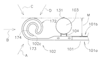
次に、本発明の第二の実施形態について説明する。図3は、本実施形態の該略を示す図である。この図に示すように、支柱103に連結部材104を装着し、この連結部材104のフランジ面105に主ビーム101を当接させつつ固定し、さらに主ビーム101に袖ビーム102を締着させる構成については、第一の実施形態と同様である。ただし、図3は、ガードレールの中心的部材である主ビーム1について、第一の実施形態とは異なる形態のものを示し、また、支柱103の形状、および当該支柱103に使用される連結部材104については異なる形態を示す。これは、本発明が各種のガードレールに使用できることを示すためであり、当然、図1に示した形態のガードレールにも使用でき、第一の実施形態が図3に示す形態のガードレールに使用してもよい。
Next, a second embodiment of the present invention will be described. FIG. 3 is a diagram showing the outline of the present embodiment. As shown in this figure, a connecting
ところで、本実施形態は、延出部107に形成される湾曲領域172を変形したものである。すなわち、湾曲領域172を渦状に形成するのではなく、最外層173は、曲率を変化させずに断面弧状としつつ、ほぼ1周に相当する範囲を湾曲させ、その終端において内側に湾曲させ、内側層174を形成するのである。この内側層174についても、ほぼ1周の断面円弧状としている。最外層173と内側層174との間には、適宜間隔Lが確保されるようにしている。このように湾曲させた場合であっても、袖ビームの端末縁部(エッジ)102cは、内側層の終縁74となることから、最外層173の内側に収めることができるのである。なお、内側層174は、さらに内側に湾曲させて、二重に設ける構成としてもよい。
By the way, this embodiment deform | transforms the curved area |
本実施形態は、上記のような構成であることから、本実施形態においてもほぼ全周方向に対して積層構造とすることができ、車両が衝突する場合、例えば、ガードレール(主ビーム1)の長手方向に対して斜状方向Aまたは平行な方向Bから衝撃を受ける際にも最外層173および内側層174によって吸収でき、ガードレール(主ビーム1)の裏面101bから衝突される場合も同様である。また、本実施形態においても、最外層173の曲率を調整して、支柱103の後方端縁131から主ビーム101までの直線距離Mの範囲内に湾曲領域を収めることができるので、歩行者等の通行に支障を来すことがないように構成することができるのである。
Since this embodiment is configured as described above, even in this embodiment, a laminated structure can be formed in substantially the entire circumferential direction. When a vehicle collides, for example, a guardrail (main beam 1) Even when an impact is received from the oblique direction A or the parallel direction B with respect to the longitudinal direction, it can be absorbed by the
このように、上述した各実施形態によれば、車両の衝突による衝撃を積層構造により緩衝させるとともに、歩行者等にも優しい構造とすることができるのである。なお、本実施形態は、基部6,106については従来と同様の構成とすることができることから、従来から使用される袖ビームを加工して湾曲領域72,172を形成させることができ、安価に製造することができる。また、基部6,10が同様の構成であれば、設置作業に特別な配慮を必要としないこととなり、容易に設置することができる。
As described above, according to each of the above-described embodiments, the impact caused by the collision of the vehicle can be buffered by the laminated structure, and the structure can be made friendly to pedestrians and the like. In the present embodiment, since the
本発明の実施形態は以上のとおりであるが、これらは一例であり、本発明が上記実施形態に限定されることを意図するものではない。すなわち、本発明の趣旨の範囲内において、種々変形することができるものである。例えば、上記実施形態は、従来の袖ビームと同じ材料を使用し、その一部を加工することによって製造することができるものであるが、湾曲領域72,172による緩衝性能を向上させるため、その材質、形状、肉厚その他の寸法を適宜変更することができる。特に、同じ材質および形状であっても、肉厚を変更することにより(厚肉にすることにより)、強度を向上させ、その結果として、可能な限り積層構造の湾曲領域72,172の範囲内で衝撃を吸収させるように設計することができる。同様に、基部6,106の強度を向上させるための各種変更も自在である。
The embodiments of the present invention are as described above, but these are merely examples, and the present invention is not intended to be limited to the above-described embodiments. That is, various modifications can be made within the scope of the gist of the present invention. For example, the above embodiment can be manufactured by using the same material as the conventional sleeve beam and processing a part thereof, but in order to improve the buffering performance by the
なお、最外層73,173と内側層74,174とで形成される間隙Lは、緩衝性能のために確保する必要があり、数mm〜数十mmの範囲で構成することを想定しているが、その最適値は材質や内側層74,174の数によって異なる。また、その内側層の数は、得るべき所望の緩衝効果の程度によって異なり、走行する車両等に対する制限速度や通行可能な車両の重量等により、予想される衝撃の程度によって変更すればよいのである。そして、袖ビーム2,102の袖ビーム端末縁部(エッジ)2c,102cの上縁及び下縁と先端縁との角を除去するため、袖ビーム端末縁部(エッジ)2c,102cの近傍から当該エッジ先端までの上縁及び下縁を先細り状に傾斜させ、またはアールを設けることにより、歩行者等が触れる際の負傷の原因を排除させるようにしてもよい。
The gap L formed by the
また、主ビーム1,101の代表例として、平板状の金属板を折り曲げた構成のものを図示したが、主ビーム1,101は、これらの構成に限定されるものではない。例えば、複数(通常は2本)のポールを水平方向に軸線を向けて支柱3,103に支持させる構成のものでもよい。そのほかに間伐材等を使用する木製の棒状部材などを前記ポールのように設置したものであってもよい。
Moreover, although the thing of the structure which bent the flat metal plate was illustrated as a typical example of the
さらに、本発明の袖ビームは、車両の衝突時の衝撃を緩和することができるため、車両が通過する場所(車道、私有地または駐車場など)に立設する各種の支柱(道路標識や看板または街路灯などのための支柱)によって支持させることにより、当該各種の支柱の防護用として使用することが可能である。この場合においても、車両の衝撃を緩和する効果のほかに、近傍を通過する歩行者または自転車との接触による交通弱者を保護し得ることとなる。 Furthermore, since the sleeve beam of the present invention can alleviate the impact at the time of the collision of the vehicle, various support columns (road signs, signboards or It is possible to use it for protection of the various pillars by supporting it with pillars for street lights and the like. Even in this case, in addition to the effect of mitigating the impact of the vehicle, it is possible to protect weak traffic persons due to contact with pedestrians or bicycles passing through the vicinity.
1,101 主ビーム
1a,101a 主ビームの表面
1b,101b 主ビームの裏面
2,102 袖ビーム
2a 境界
2b 渦巻きの中心
2c,102c 袖ビーム端末縁部(エッジ)
3,103 支柱
4,104 連結部材
5,105 フランジ面
6,106 袖ビームの基部
7,107 袖ビームの延出部
11 主ビームの端部
12,13 主ビームの斜状面
14,15 主ビームの凹状部分
16,17,18 主ビームの凸状部分
21 袖ビームの端部(基端側端部)
31,131 支柱の後方縁部
61,62 袖ビームの連結部
71 延出部の平面領域
72 延出部の湾曲領域
73 最外層
74 内側層
DESCRIPTION OF SYMBOLS 1,101
3,103 Column 4,104 Connecting member 5,105 Flange surface 6,106
31 and 131
Claims (3)
前記主ビームに連結される基部と、該基部から水平方向に延出する板状の延出部とを備え、
前記延出部は、前記主ビームの表面に連続する平面領域と、該平面領域に連続する端末側を前記主ビームの裏面側に湾曲させた湾曲領域とに区分され、前記湾曲領域は、小さい曲率で湾曲させた最外層と、該最外層の内側において適宜間隔を確保しつつ大きい曲率に湾曲させた内側層とが一体的に形成され、前記延出部の端末縁部が内側層の終端に配置されていることを特徴とするガードレール端末部緩衝袖ビーム。 In a guardrail comprising a plurality of struts installed at appropriate intervals and a main beam supported while abutting the back surface against the struts, a sleeve beam provided continuously at a terminal portion of the main beam,
A base connected to the main beam; and a plate-like extension extending horizontally from the base;
The extending portion is divided into a planar region continuous with the surface of the main beam and a curved region where the terminal side continuous with the planar region is curved toward the back surface side of the main beam, and the curved region is small An outermost layer curved with a curvature and an inner layer curved with a large curvature while securing an appropriate interval inside the outermost layer are integrally formed, and the terminal edge of the extension portion is the end of the inner layer Guardrail terminal part buffer sleeve beam characterized by being arranged in.
Priority Applications (1)
| Application Number | Priority Date | Filing Date | Title |
|---|---|---|---|
| JP2013233187A JP2015094100A (en) | 2013-11-11 | 2013-11-11 | Sleeve beam for guard rail end part buffering |
Applications Claiming Priority (1)
| Application Number | Priority Date | Filing Date | Title |
|---|---|---|---|
| JP2013233187A JP2015094100A (en) | 2013-11-11 | 2013-11-11 | Sleeve beam for guard rail end part buffering |
Publications (1)
| Publication Number | Publication Date |
|---|---|
| JP2015094100A true JP2015094100A (en) | 2015-05-18 |
Family
ID=53196708
Family Applications (1)
| Application Number | Title | Priority Date | Filing Date |
|---|---|---|---|
| JP2013233187A Pending JP2015094100A (en) | 2013-11-11 | 2013-11-11 | Sleeve beam for guard rail end part buffering |
Country Status (1)
| Country | Link |
|---|---|
| JP (1) | JP2015094100A (en) |
Cited By (12)
| Publication number | Priority date | Publication date | Assignee | Title |
|---|---|---|---|---|
| CN106592472A (en) * | 2017-01-22 | 2017-04-26 | 合肥饰界金属制品有限公司 | Road guardrail |
| CN106592471A (en) * | 2017-01-22 | 2017-04-26 | 合肥饰界金属制品有限公司 | Road protection fence |
| CN106702926A (en) * | 2017-01-22 | 2017-05-24 | 合肥饰界金属制品有限公司 | Road guard railing |
| CN106758977A (en) * | 2017-01-22 | 2017-05-31 | 合肥饰界金属制品有限公司 | Guard rail |
| CN106758975A (en) * | 2017-01-22 | 2017-05-31 | 合肥饰界金属制品有限公司 | Highway guard rail |
| CN106758976A (en) * | 2017-01-22 | 2017-05-31 | 合肥饰界金属制品有限公司 | Road guard-rail |
| CN106758978A (en) * | 2017-01-22 | 2017-05-31 | 合肥饰界金属制品有限公司 | Road guard-rail |
| CN106812087A (en) * | 2017-01-22 | 2017-06-09 | 合肥饰界金属制品有限公司 | Road guard-rail |
| CN106812088A (en) * | 2017-01-22 | 2017-06-09 | 合肥饰界金属制品有限公司 | Highway guard rail |
| CN106812086A (en) * | 2017-01-22 | 2017-06-09 | 合肥饰界金属制品有限公司 | Road guard-rail |
| CN106948656A (en) * | 2017-03-31 | 2017-07-14 | 安徽卓航展示用品有限公司 | guard rail |
| CN107060307A (en) * | 2017-05-15 | 2017-08-18 | 葛加君 | Construction simplification triangle operating platform makes and construction method of installation |
-
2013
- 2013-11-11 JP JP2013233187A patent/JP2015094100A/en active Pending
Cited By (12)
| Publication number | Priority date | Publication date | Assignee | Title |
|---|---|---|---|---|
| CN106592472A (en) * | 2017-01-22 | 2017-04-26 | 合肥饰界金属制品有限公司 | Road guardrail |
| CN106592471A (en) * | 2017-01-22 | 2017-04-26 | 合肥饰界金属制品有限公司 | Road protection fence |
| CN106702926A (en) * | 2017-01-22 | 2017-05-24 | 合肥饰界金属制品有限公司 | Road guard railing |
| CN106758977A (en) * | 2017-01-22 | 2017-05-31 | 合肥饰界金属制品有限公司 | Guard rail |
| CN106758975A (en) * | 2017-01-22 | 2017-05-31 | 合肥饰界金属制品有限公司 | Highway guard rail |
| CN106758976A (en) * | 2017-01-22 | 2017-05-31 | 合肥饰界金属制品有限公司 | Road guard-rail |
| CN106758978A (en) * | 2017-01-22 | 2017-05-31 | 合肥饰界金属制品有限公司 | Road guard-rail |
| CN106812087A (en) * | 2017-01-22 | 2017-06-09 | 合肥饰界金属制品有限公司 | Road guard-rail |
| CN106812088A (en) * | 2017-01-22 | 2017-06-09 | 合肥饰界金属制品有限公司 | Highway guard rail |
| CN106812086A (en) * | 2017-01-22 | 2017-06-09 | 合肥饰界金属制品有限公司 | Road guard-rail |
| CN106948656A (en) * | 2017-03-31 | 2017-07-14 | 安徽卓航展示用品有限公司 | guard rail |
| CN107060307A (en) * | 2017-05-15 | 2017-08-18 | 葛加君 | Construction simplification triangle operating platform makes and construction method of installation |
Similar Documents
| Publication | Publication Date | Title |
|---|---|---|
| JP2015094100A (en) | Sleeve beam for guard rail end part buffering | |
| KR101182975B1 (en) | Guard rail structure | |
| KR101009538B1 (en) | Shocking absorption safety fence | |
| JP5962991B2 (en) | Guard fence and installation method of guard fence | |
| KR20190032021A (en) | A road protective fence having multi buffering function | |
| KR100847736B1 (en) | Guardrail for impact absorption using wire rope | |
| KR101294724B1 (en) | A vehicle guard fence | |
| KR101791997B1 (en) | Shock-absorbing guardrail for road having buffer structure | |
| KR101089910B1 (en) | Separating type guard rail | |
| KR101351197B1 (en) | Shock-absorbing Apparatus for Guard Rail | |
| KR102592572B1 (en) | Guard rail | |
| KR101613275B1 (en) | The Rotary shock absorber device for guardrail | |
| KR200383560Y1 (en) | A guard rail provide with safety sock-absorber device | |
| KR102238512B1 (en) | Guardrail coupling structure with improved durability | |
| KR101938143B1 (en) | Semi-rigid cable barrier and asymmetrical slip block-out thereof | |
| KR20130068744A (en) | Guardrail with energy absorber | |
| JP3831776B2 (en) | Guardrail shock absorbing structure | |
| KR101948987B1 (en) | Guardrail post structure | |
| KR101141690B1 (en) | Guard rail having asymmetric shock absorbing member | |
| KR101190671B1 (en) | Guardrail | |
| CN106702924B (en) | Anticollision barrier | |
| JP6305716B2 (en) | Guard pipe end shock absorber and guard pipe using the same | |
| JP6345959B2 (en) | Shock absorbing fence | |
| KR20190073193A (en) | Guard fence for vehicle with impact absorption and fixing funtion | |
| AU2006235944A1 (en) | Shock absorber for road safety barrier |