JP2015078043A - Long object hooking detection device of elevator - Google Patents
Long object hooking detection device of elevator Download PDFInfo
- Publication number
- JP2015078043A JP2015078043A JP2013215997A JP2013215997A JP2015078043A JP 2015078043 A JP2015078043 A JP 2015078043A JP 2013215997 A JP2013215997 A JP 2013215997A JP 2013215997 A JP2013215997 A JP 2013215997A JP 2015078043 A JP2015078043 A JP 2015078043A
- Authority
- JP
- Japan
- Prior art keywords
- long object
- rope
- elevator
- distance
- unit
- Prior art date
- Legal status (The legal status is an assumption and is not a legal conclusion. Google has not performed a legal analysis and makes no representation as to the accuracy of the status listed.)
- Granted
Links
Images


Classifications
-
- B—PERFORMING OPERATIONS; TRANSPORTING
- B66—HOISTING; LIFTING; HAULING
- B66B—ELEVATORS; ESCALATORS OR MOVING WALKWAYS
- B66B5/00—Applications of checking, fault-correcting, or safety devices in elevators
- B66B5/02—Applications of checking, fault-correcting, or safety devices in elevators responsive to abnormal operating conditions
- B66B5/021—Applications of checking, fault-correcting, or safety devices in elevators responsive to abnormal operating conditions the abnormal operating conditions being independent of the system
- B66B5/022—Applications of checking, fault-correcting, or safety devices in elevators responsive to abnormal operating conditions the abnormal operating conditions being independent of the system where the abnormal operating condition is caused by a natural event, e.g. earthquake
-
- B—PERFORMING OPERATIONS; TRANSPORTING
- B66—HOISTING; LIFTING; HAULING
- B66B—ELEVATORS; ESCALATORS OR MOVING WALKWAYS
- B66B5/00—Applications of checking, fault-correcting, or safety devices in elevators
- B66B5/0006—Monitoring devices or performance analysers
- B66B5/0018—Devices monitoring the operating condition of the elevator system
- B66B5/0031—Devices monitoring the operating condition of the elevator system for safety reasons
Landscapes
- Life Sciences & Earth Sciences (AREA)
- Engineering & Computer Science (AREA)
- Environmental & Geological Engineering (AREA)
- General Life Sciences & Earth Sciences (AREA)
- Geology (AREA)
- Remote Sensing (AREA)
- Maintenance And Inspection Apparatuses For Elevators (AREA)
- Operating, Guiding And Securing Of Roll- Type Closing Members (AREA)
Abstract
Description
本発明は、ロープなどの長尺物がエレベーター機器に引掛かっていることを、画像を用いて検出するエレベーターの長尺物引掛り検出装置に関する。 The present invention relates to a long object catch detection device for an elevator that uses an image to detect that a long object such as a rope is hooked on an elevator device.
地震等で大きく揺れて停止したエレベーターはロープが昇降路内の機器に引掛かっているおそれがあるため、揺れ収束後も自動復旧することができない。そこで、揺れの収束後に保全員を現場に派遣してロープが引掛かっていないことを確認したうえで復旧する。しかし、保全員が地震等の収束後に都市部のすべてのエレベーターを点検するためには多くの時間を要し、このため復旧が遅れる。これに対し、ロープの引掛りの有無を自動的に判定する技術が知られている。 An elevator that has been greatly shaken and stopped by an earthquake or the like cannot be automatically restored even after the shaking has converged because there is a risk that the rope may be caught by equipment in the hoistway. Therefore, after the shaking has converged, a maintenance worker is dispatched to the site to confirm that the rope is not caught and then recover. However, it takes a lot of time for maintenance personnel to check all the elevators in urban areas after the earthquake has converged, which delays recovery. On the other hand, a technique for automatically determining whether or not a rope is caught is known.
例えば、特許文献1に記載の技術では、建物最上階のロープ出口近傍に設けたロープ変位検知手段で地震発生から一定時間経過後のロープ位置を検出し、通常時のロープ位置と比較し、しきい値を超えた場合に引掛かりが発生していると判定する。
For example, in the technique described in
また、特許文献2に記載の技術では、ガバナロープの引掛り、切断、外れを検出するために、ガバナロープテンションウェイトの最下床からの位置を計測することでガバナロープテンションシーブの位置を計測し、基準位置よりも上方に移動した場合に引掛りが発生したと判定する。
In the technique described in
特許文献1に記載の技術では、建物最上階のロープ出口において、地震発生から一定時間経過後のロープ位置を計測し、通常時のロープ位置と比較し、所定の振れ幅を超えて振れている場合に引掛りが発生していると判定している。しかし超高層ビルのエレベーターで、数百メートルに及ぶロープの引掛りの有無を建物最上階で計測されるロープ位置から判断することは難しい。
In the technique described in
特許文献2に記載の技術では、引掛りによって生じるガバナロープテンションウェイト及びガバナロープテンションシーブの上方への変位を検出するものである。しかし、エレベーターに用いられるロープは複数のストランドが撚り合わせられたもので、ばねのように伸縮したり、撚りが締まることにより伸びたりする。したがって、超高層ビルのように数百メートルに及ぶロープの最下端の位置の上昇から引掛りを検出することは難しい。
In the technique described in
そこで、本発明は、昇降路内の突起物へのロープなどの長尺物の引掛りの有無を確実に判定できるエレベーターの長尺物引掛り検出装置を提供する。 Therefore, the present invention provides a long object catch detection device for an elevator that can reliably determine whether a long object such as a rope is caught on a protrusion in a hoistway.
上記課題を解決するために、本発明によるエレベーターの長尺物引掛り検出装置は、エレベーターの昇降路内における突起物への長尺物の引掛りを昇降路内の画像によって検出するものであって、昇降路内の画像を取得する撮像部と、撮像部が取得した画像に基づいて、突起物と長尺物との距離もしくは長尺物が向かう方向を計測する計測部と、計測部が計測した突起物と長尺物との距離もしくは長尺物が向かう方向に基づいて突起物への長尺物の引掛りの有無を判定する判定部とを備える。 In order to solve the above-mentioned problems, an elevator long object catch detection device according to the present invention detects the catch of a long object on a protrusion in an elevator hoistway from an image in the hoistway. An imaging unit that acquires an image in the hoistway, a measurement unit that measures a distance between the projection and the long object, or a direction in which the long object is directed based on the image acquired by the imaging unit, and a measurement unit And a determination unit that determines whether the long object is caught on the protrusion based on the measured distance between the protrusion and the long object or the direction in which the long object is directed.
昇降路内の画像から計測される突起物と長尺物との距離もしくは長尺物が向かう方向に基づくことにより、突起物への長尺物の引掛りの有無を正確に判定することができる。 Based on the distance between the protrusion and the long object measured from the image in the hoistway or the direction in which the long object heads, it is possible to accurately determine whether the long object is caught on the protrusion. .
上記した以外の課題、構成および効果は、以下の実施形態の説明により明らかにされる。 Problems, configurations, and effects other than those described above will become apparent from the following description of embodiments.
以下、図面を用いて実施例を説明する。 Embodiments will be described below with reference to the drawings.
[原理説明]
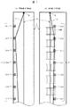
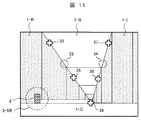
図1は、昇降路内においてロープが突起物に引掛った様子を示す。図1(a)はエレベーター昇降路1内を乗場ドア100の側面方向から見た図であり、図1(b)は同昇降路1内を乗場ドア100の正面側方向から見た図である。エレベーターの乗りかごの上部には停止階床検出装置(図示せず)が設置されているが、これは磁気センサまたは光電センサである。そして、昇降路側には、各階床のドアの上部に遮蔽板2(構造の詳細は図示せず)が取り付けられている。遮蔽板2(2−1〜2−7)は、エレベーターの乗りかごがいずれかの階床に停止した場合に、遮蔽板2のいずれかが、停止階床検出装置の磁気または光を遮ることにより、乗りかごの停止または停止位置を検出する。このため、遮蔽板2は、昇降路の上階床から下階床に至るまで、鉛直方向すなわち重力方向に一列に並んで取り付けられる。
[Principle explanation]
FIG. 1 shows a state in which a rope is caught on a protrusion in a hoistway. FIG. 1A is a view of the
なお、図1中、図示の便宜上、遮蔽板2に模様を記しているが、実際の遮蔽板の構造を示すものではない(他の図も同様)。
In FIG. 1, for convenience of illustration, a pattern is shown on the
昇降路内において突起物となる機器にはロープの引掛りを防止するためのガードが取り付けられる場合があるが、遮蔽板2には、上記機能のためにガードを取り付けない。このため、遮蔽板2はロープが引掛るおそれがある突起物である。
A guard for preventing the rope from being caught may be attached to a device that becomes a protrusion in the hoistway, but the
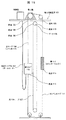
図1において、破線で示したロープ3は引掛りの無い状態である。ここで、図中のSは、ロープの起点を示す。ロープの起点の具体例は、例えば、図15に示している。図15はロープの起点の具体例を示すための昇降機の例示であって、制御ケーブル(テールコードとも呼ばれる)102が巻上機設置床101の下側に垂れており、その部分の最上部が、制御ケーブル102の起点103である。主ロープ104において、巻上機設置床101の下側に垂れている部分の最上部が、主ロープ104の起点105および106である。ガバナロープ107はプーリ108で折り返されており、ガバナロープ107がプーリ108から離れる場所が、ガバナロープ107の起点109および110である。コンペンロープ111は、乗りかご112と錘114に連結している。コンペンロープ111が乗りかご112と錘114に連結している箇所は、それぞれ、コンペンロープ111の起点113および115である。なお、ロープ3は、引掛りの無い状態であっても、左右に揺れることもあるが、図1ではその様子は図示されていない。ロープ3としては、制御ケーブル102(これもロープの一種とみなすことができる),主ロープ104,ガバナロープ107,コンペンロープ111などの様々なものがあるが、これらは多少の揺れを伴って重力方向に垂れている。また、これらのロープは、揺れによって一時的に遮蔽板2に接近することはあるものの、定常的には遮蔽板2から一定距離だけ離れた所で重力方向に垂れている。なお、これらのロープは、最下階床でプーリによってU字型に折り返されていても良い(図15参照)。
In FIG. 1, the
図1において、実線で示したロープ4は、上から二番目の遮蔽板2−2に引掛かっている。ロープ4は、引掛りにより、建物最上部のロープの起点Sから遮蔽板2−2に向かっている。図1では直線で表しているが、実際にはロープ4の自重により懸垂曲線になっている場合もある。ロープ4は、遮蔽板2−2に引掛かった部分から先は、より下階床の遮蔽板2−3ないし2−7に近接してほぼ鉛直方向に垂れている。
In FIG. 1, the
図2は、本発明の第一の実施例であるエレベーターの長尺物引掛り検出装置が備える撮像部の取り付け態様を示す。撮像部としては、例えばカメラが用いられる。撮像部は遮蔽板2が取り付けられている昇降路壁に、昇降路壁と略同一平面上に設置される。ここで、図2(a)は、乗場ドア100のある昇降路1の壁正面を示し、図2(b)は、昇降路1の乗場ドアのある壁の断面を示す。図2(a)と図2(b)には、撮像部5の設置態様を三例示す。撮像部(5−1,5−2,5−3)は、いずれも遮蔽板2の設置されている昇降路壁に設置されている。これにより、ロープが撮像部5に引っ掛かり易くなることが防止できる。撮像部5−1は、遮蔽板2の鉛直に並ぶ列から外れるように、遮蔽板2を見降ろす位置から水平に所定距離、例えば1メートル前後移動した位置に設置される。撮像部5−2は、斜め下方に遮蔽板2を見降ろす位置に設置される。撮像部5−3は、水平方向に遮蔽板2を撮影するように設置される。
FIG. 2 shows an attachment mode of the image pickup unit provided in the long object catch detection apparatus for an elevator according to the first embodiment of the present invention. For example, a camera is used as the imaging unit. The imaging unit is installed on the hoistway wall to which the
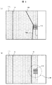
図3は、図2の撮像部5−1で昇降路1の内側を撮影して得られる画像の例である。画面下方の白い領域1−Cは昇降路1の壁であって、乗場ドアのある側の壁である。画面左方に遮蔽板2−2が写っている。なお、領域1−Cおよび遮蔽板2−2に接する長方形の白い領域Aは、乗場ドアの上部あるいは乗場の敷居(シル)を示す。
FIG. 3 is an example of an image obtained by photographing the inside of the
図3(a)のように遮蔽板2−2のある階床に設置された撮像部5−1の画像においては、遮蔽板2−2が写っている。図中、点描領域1−Lは、昇降路内において乗場ドアに向かって左方に位置する昇降路壁である。点描領域1−Rは、昇降路内において乗場ドアに向かって右方に位置する昇降路壁である。白い領域1−Bは、乗場ドアに対向する昇降路壁である。 As shown in FIG. 3A, the shielding plate 2-2 is shown in the image of the imaging unit 5-1 installed on the floor where the shielding plate 2-2 is located. In the figure, the stippling region 1-L is a hoistway wall located on the left side of the hoistway toward the landing door. The stippling region 1-R is a hoistway wall located on the right side of the hoistway toward the landing door. White region 1-B is a hoistway wall facing the landing door.
図3(a)においては、上層から下層にかけての各階床の境目が判るように、線分F1ないしF4を付してある。また、昇降路1の各壁の境界である線分同志は下方に延びて一点に集中する。この一点は、鉛直方向の消失点であり、重力に従うロープもこの消失点に向かう。例えば、破線で示すロープ6ないし8は皆、直接、消失点に向かっており、引掛りの無いロープである。一方、実線で示すロープ9(9A,9B)は、遮蔽板2−2に引っ掛かっているロープである。特にロープ9Aの部分は遮蔽板2−2に向かう方向を取っていて、引掛りの無いロープが消失点に向かうのと異なる方向に向かっている。しかし、ロープ9Bの部分は消失点に向かっている。このように重力方向すなわち消失点に向かう方向と異なる方向に沿って遮蔽板2−2に向かうロープは、遮蔽板2−2に引っ掛かっていると判断することができる。
In FIG. 3A, line segments F1 to F4 are added so that the boundary between each floor from the upper layer to the lower layer can be understood. Moreover, the line segments which are the boundary of each wall of the
図3(b)は、図3(a)のようにロープが遮蔽板2−2に引掛っている場合に、遮蔽板2−5のある階床に設置した撮像部5−1で昇降路1の内側を撮影して得られる画像の例である。ここで、遮蔽板2−5の位置を中心として所定の半径の距離円2−5Rを設定しておくと、実線で示したロープ10のように、距離円2−5Rの内部を通るロープ、すなわち遮蔽板2−5に対し所定の距離以下に接近しているロープは、遮蔽板2−5以外の遮蔽板に引掛かっていると判断することができる。
FIG. 3B shows a hoistway in the imaging unit 5-1 installed on the floor with the shielding plate 2-5 when the rope is hooked on the shielding plate 2-2 as shown in FIG. 2 is an example of an image obtained by photographing the inside of 1. Here, when a distance circle 2-5R having a predetermined radius is set around the position of the shielding plate 2-5, a rope passing through the inside of the distance circle 2-5R, like the
以上説明したように、各階床において撮像部5−1を設置して遮蔽板2を視野に入れて撮影した画像に、撮影された遮蔽板に向かうロープ、あるいは撮影された遮蔽板に所定の距離以下に接近しているロープが撮影されている場合は、いずれかの遮蔽板にロープが引掛かっていると判断することができる。
As described above, the image capturing unit 5-1 is installed on each floor and the image taken with the shielding
図4は、図2の撮像部5−2で昇降路1の内側を撮影して得られる画像の例である。画面下方の白い領域1−Cは、乗場ドアのある側の昇降路壁である。画面内に複数の遮蔽板2が写っているが、その内、最も右側に写っている、最も大きな遮蔽板が、撮像部5−2が設置された階床に設けられた遮蔽板である。
FIG. 4 is an example of an image obtained by photographing the inside of the
図4(a)のように、遮蔽板2−2のある階床に設置された撮像部5−2の画像においては、遮蔽板2−2が写っている。図中、点描領域1−Lは、昇降路内において乗場ドアに向かって左方に位置する昇降路壁である。白領域1−Bは乗場ドアに対向する昇降路壁である。昇降路1の各壁の境界である線分同志は下方に延びて一点に集中する。この一点は、鉛直方向の消失点であり、重力に従うロープもこの消失点に向かう。例えば、破線で示すロープ11は、直接、消失点に向かっており、引掛りの無いロープである。一方、実線で示すロープ12(12A,12B)は、遮蔽板2−2に引掛かっているロープである。特にロープ12Aの部分は遮蔽板2−2に向かう方向を取っていて、引掛りの無いロープが消失点に向かうのと異なる方向に向かっている。しかし、ロープ12Bの部分は消失点に向かっている。このように重力方向すなわち消失点に向かう方向と異なる方向に沿って遮蔽板2−2に向かうロープは、遮蔽板2−2に引掛かっていると判断することができる。
As shown in FIG. 4A, in the image of the imaging unit 5-2 installed on the floor with the shielding plate 2-2, the shielding plate 2-2 is shown. In the figure, the stippling region 1-L is a hoistway wall located on the left side of the hoistway toward the landing door. White region 1-B is a hoistway wall facing the landing door. Line segments that are boundaries between the walls of the
図4(b)は、図4(a)のようにロープが遮蔽板2−2に引掛っている場合に、遮蔽板2−5のある階床に設置した撮像部5−2で昇降路1の内側を撮影して得られる画像の例である。ここで、遮蔽板2−5の位置を中心として所定の半径の距離円2−5Rを設定しておくと、実線で示したロープ13のように、距離円2−5Rの内部を通るロープ、すなわち遮蔽板2−5に所定の距離以下に接近しているロープは、遮蔽板2−5以外の遮蔽板に引掛かっていると判断することができる。
FIG. 4B shows a hoistway in the imaging unit 5-2 installed on the floor with the shielding plate 2-5 when the rope is hooked on the shielding plate 2-2 as shown in FIG. 4A. 2 is an example of an image obtained by photographing the inside of 1. Here, when a distance circle 2-5R having a predetermined radius is set around the position of the shielding plate 2-5, a rope passing through the inside of the distance circle 2-5R, like a
以上説明したように、各階床において撮像部5−2を設置して遮蔽板2を視野に入れて撮影した画像に、撮影された遮蔽板に向かうロープ、あるいは撮影された遮蔽板に所定の距離以下に接近しているロープが撮影されている場合は、いずれかの遮蔽板にロープが引掛かっていると判断することができる。
As described above, the image capturing unit 5-2 is installed on each floor and the image taken with the shielding
図5は、図2の撮像部5−3で昇降路1の内側を撮影して得られる画像の例である。図中、点描領域1−Lは、昇降路内において乗場ドアに向かって左方に位置する昇降路壁である。
FIG. 5 is an example of an image obtained by photographing the inside of the
図5(a)のように遮蔽板2−2のある階床に設置された撮像部5−3の画像においては、遮蔽板2−2が写っている。本図の場合、重力の方向は画像の下方である。図中、破線で示すロープ14は、直接下方すなわち重力方向に平行な方向に向かっており、引掛りの無いロープである。一方、実線で示すロープ15(15A,15B)は、遮蔽板2−2に引掛かっているロープである。特にロープ15Aの部分は遮蔽板2−2に向かう方向を取っていて、引掛りの無いロープ14が直接画面下方に向かうのと異なる方向に向かっている。しかし、ロープ15Bの部分はほぼ下方に向かっている。このように重力方向と異なる方向に沿って遮蔽板2−2に向かうロープは、遮蔽板2−2に引掛かっていると判断することができる。
As shown in FIG. 5A, in the image of the imaging unit 5-3 installed on the floor with the shielding plate 2-2, the shielding plate 2-2 is shown. In the case of this figure, the direction of gravity is below the image. In the drawing, a
図5(b)は、図5(a)のようにロープが遮蔽板2−2に引掛っている場合に、遮蔽板2−5のある階床に設置した撮像部5−3で昇降路1の内側を撮影して得られる画像の例である。ここで、遮蔽板2−5の位置を中心として所定の半径の距離円2−5Rを設定しておくと、実線で示したロープ16のように、距離円2−5Rの内部を通るロープ、すなわち遮蔽板2−5に所定の距離以下に接近しているロープは、遮蔽板2−5以外の遮蔽板に引掛かっていると判断することができる。
FIG. 5B shows a hoistway in the imaging unit 5-3 installed on the floor with the shielding plate 2-5 when the rope is hooked on the shielding plate 2-2 as shown in FIG. 5A. 2 is an example of an image obtained by photographing the inside of 1. Here, when a distance circle 2-5R having a predetermined radius is set around the position of the shielding plate 2-5, a rope passing through the inside of the distance circle 2-5R, like a
以上説明したように、各階床においてカメラ5−3を設置して遮蔽板2を視野に入れて撮影した画像に、撮影された遮蔽板に向かうロープ、あるいは撮影された遮蔽板に所定の距離以下に接近しているロープが撮影されている場合は、いずれかの遮蔽板にロープが引掛かっていると判断することができる。
As described above, the camera 5-3 is installed on each floor and the image taken with the shielding
図6は、撮像部の他の取付け態様を示す。ここで、図6(a)は、乗場ドア100のある昇降路1の壁正面を示し、図6(b)は、昇降路1の乗場ドアのある壁の断面を示す。本態様において、撮像部5−4は、遮蔽板2の真上に位置する。なお、図2に示した態様と同様に、撮像部5−4は、遮蔽板2が取り付けられている昇降路壁において、この昇降路壁と略同一平面上に設置される。
FIG. 6 shows another mounting mode of the imaging unit. 6A shows the front of the wall of the
これまで、「距離」の語は平面上の画像上の2点間の距離の意味として用いてきた。以後もこの用い方を維持しつつ、例えばステレオカメラで計測するような3次元的(立体的)な距離については、「3次元的距離」の語を用いる。 So far, the term “distance” has been used to mean the distance between two points on an image on a plane. The word “three-dimensional distance” is used for a three-dimensional (stereoscopic) distance that is measured by, for example, a stereo camera while maintaining this usage.
図7は、図6の撮像部5−4で昇降路1の内側を撮影して得られる画像の例である。この画像では、遮蔽板2−2と消失点が重なっているため、ロープ17は、引掛りの有無に関係無く、遮蔽板2及び消失点に向かう。このような場合には、撮像部5−4として、3次元距離センサを用い、3次元的距離を計測できるステレオカメラやTime of Flightカメラなどを適用する。すなわち、遮蔽板2−2とロープ17の3次元的距離を計測し、ロープ17の引掛りが無い場合よりも、所定の3次元的距離の範囲内で距離が近接している場合には、引掛りが発生していると判断し、近接していなければ引掛りは生じていないと判断できる。ここで、前記所定の3次元的距離とは、例えば、遮蔽板2−2を中心とする球であって、その半径を距離円2−5Rと同一のものとした場合の前記球の内側と定義することができる。
[構成例]
図8は、本発明の第一の実施例であるエレベーターの長尺物引掛り検出装置の構成を示すブロック図である。エレベーターの長尺物引掛り検出装置20は、撮像部5と、設定ツール21と、領域マップ保持部25と、時間平均化部26と、ロープ検出部27と、方向計測部28と、距離計測部29と、引掛り有無判定部30と、判定結果出力部31を備える。そして、設定ツール21は、表示部22と、指示部23と、領域マップ作成部24を備える。
FIG. 7 is an example of an image obtained by photographing the inside of the
[Configuration example]
FIG. 8 is a block diagram showing the configuration of the long object catch detection device for an elevator according to the first embodiment of the present invention. The elevator long object
ここで、撮像部5,表示部22,指示部23,領域マップ保持部25としては、例えば、それぞれ、カメラ,ディスプレイ装置,ポインティングデバイス,メモリ装置が用いられる。また、領域マップ作成部24,時間平均化部26,ロープ検出部27,方向計測部28,距離計測部29,引掛り有無判定部30,判定結果出力部31の各機能は、例えば、マイクロコンピュータなどの演算処理装置が、各機能に対応する処理プログラムに従って動作することにより得られる。なお、判定結果出力部31は、判定結果を報知するための表示装置や音声発生装置などを備える。
Here, as the
設定ツール21は、撮像部5の設置時に、撮像部5によって取り込んだ画像内における昇降路内部の構造に応じた領域マップを作成する。作成された領域マップは、領域マップ保持部25に保持される。領域マップにおいては、図3ないし5に示したような昇降路1内の画像における遮蔽板2の位置,遮蔽板2にロープが引掛っている場合の遮蔽板とロープとの間の距離の範囲(遮蔽板からの距離のしきい値)である距離円2−5R,消失点の位置若しくは重力方向が、座標値と数値で記録されている。領域マップは撮像部5の画角調整時に作成すればよいので、設定ツール21は、エレベーターの長尺物引掛り検出装置20において着脱可能に接続しても良い。
The
撮像部5は、昇降路内の映像を逐次取得する。領域マップ保持部25は、領域マップを保持する。なお、図8におけるAは、単に信号が接続していることを示すものである。
The
時間平均化部26と、ロープ検出部27と、方向計測部28と、距離計測部29は、各々、領域マップを参照して必要な領域のみに画像処理を施すものとしてもよい。なお、エレベーターの長尺物引掛り検出装置20は、建物に設置された振動センサ(図示せず)等で地震などによる揺れの収束を確認してから動作させることができる。揺れが収束して、かつ、エレベーターも停止中であるためにロープに揺れや移動が無いことが明らかな場合には、時間平均化部26の処理を省いて、撮像部5で得た画像を直接用いてロープの引掛りの有無を検出してもよい。
The
また、領域マップを参照して画像処理を行うことで必要な領域のみについて処理することができる。これより、処理を実行する演算処理装置の処理量を削減でき、更に、余計なノイズの影響による誤検出を抑制することもできる。一例として、図3においては、遮蔽板2−2または遮蔽板2−5を含む領域1−R(図3(a),図3(b)のそれぞれ左方のドット表示領域)のみに処理を施せばよい。図4と図5においては、遮蔽板2−2または遮蔽板2−5を含む領域1−L(ドット表示領域)のみに処理を施せばよい。なお、ロープが引掛かっていないのに、引掛かっていると判定して出力することを誤検出あるいは誤報と記す。 Further, only necessary areas can be processed by performing image processing with reference to the area map. As a result, the processing amount of the arithmetic processing device that executes the processing can be reduced, and further, erroneous detection due to the influence of extra noise can be suppressed. As an example, in FIG. 3, the process is performed only on the area 1-R including the shielding plate 2-2 or the shielding plate 2-5 (dot display areas on the left side of FIGS. 3A and 3B). Just give it. In FIG. 4 and FIG. 5, it is only necessary to perform processing only on the area 1-L (dot display area) including the shielding plate 2-2 or the shielding plate 2-5. In addition, it is described as a false detection or false report that a rope is not hooked but is determined to be hooked and output.
時間平均化処理部26は、撮像部5で得た一連のコマ画像(フレーム)の時間的に近接する所定のフレーム数分を加算平均する処理を実行する。この処理により、振れ幅の大きなロープはぼやけてコントラストを失う。一方で、正常に重力方向に垂れているロープと、引掛りが生じて振れ幅の少なくなったロープについては、加算平均によってコントラストを失うことは無い。むしろ、照明の変動や虫が画面を横切る等のノイズが除去されるので、次段のロープ検出部27の処理にとって有利になる。
The time averaging
ロープ検出部27はロープを検出する。ロープ検出部27に入力された画像に対して公知のソーベルフィルター等の輪郭強調処理を加えた後に二値化して画像内の輪郭を検出する。このとき、ロープ以外のノイズ輪郭も検出される可能性がある。これを抑制するために、例えば、撮像部5に用いるレンズを焦点深度の浅いものを選択して、遮蔽板2の近傍のみにフォーカスが合うように調整する。このようにすると、引掛かっている可能性の無いロープすなわち、遮蔽板2から一定距離以上離れているロープは、フォーカスずれによるボケにより輪郭として検出され難くなる。また、輪郭強調後に二値化した画像に対して、公知のHough変換などの直線成分の検出処理を行い、所定の得票値を得た候補のみをロープとみなし、これ以外をノイズとして除外することもできる。また、引掛りの無いことを保証した状態であって、揺れの少ない状態で撮影した画像を基準画像として、ロープ検出部27への入力画像と基準画像の差分処理をし、差分処理後の画像に対してソーベルフィルターによる輪郭強調を施してもよいし、二値化処理後にHough変換を施してもよい。ロープ揺れの少ない状態で取得した基準画像は遮蔽板2の近傍にロープは現われていないため、遮蔽板2に接近したり、遮蔽板2に向かったりするロープが存在する場合にはこれらの差分を容易に検出できる。ロープ検出部27は、このようにロープ候補の輪郭を所定のしきい値で二値化した画像を出力する。
The
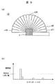
方向計測部28は例えば図9の(a)に示すように、遮蔽板2を中心としたサークルコード状のサークルテンプレート32に基づいて、ロープ検出部27の出力した二値画像におけるロープ候補の画素にコードを付す。例えば、ロープ候補のある画素がコードc01の略扇状の枠内にあれば当該画素にコードc01を付す。ロープ候補の全画素にコード付けした後はコード毎に画素数を算出して、図9の(b)に示すように、角度コードヒストグラムを作成し、所定のしきい値を超える画素数を有する角度コードが存在するかを判定し、存在する場合には、前記所定のしきい値を超える角度コードのコード数(ここでいう「コード数」とは、例えば「c01」「c02」・・・「c09」・・・「c18」など、どのコードであるかを特定する情報のことを意味する)を方向計測部28の出力とする。前記所定のしきい値を超える角度コードが存在する場合は、遮蔽板2に向かうロープが存在することを意味している。逆に、ロープが違う方向に向かっている場合には、ロープ候補の画素は特定のコードに集中しなくなるので、前記所定のしきい値を超えない。この場合は、出力をしないか、該当しないことを意味するコード数(例えばc00)を出力する。これにより、ロープが向かう方向を計測することができる。
For example, as shown in FIG. 9A, the
距離計測部29は、ロープ検出部27の出力二値画像におけるロープ候補の画素で、距離円2−R内に含まれる画素数を計数し、引掛り有無判定部30に計数した画素数を出力する。これにより、突起物である遮蔽板と、長尺物であるロープとの距離が計測できる。この場合は、「距離を計測する」とは、ロープが距離円内に存在するか否か(遮蔽板とロープとの間の距離が所定の距離以下か否か)を計測していることを意味する。
The
引掛り有無判定部30は、方向計測部28の出力において前記所定のしきい値を超えるコード数がある時は、遮蔽板2に向かうロープが存在すると判定する。また、引掛り有無判定部30は、距離計測部29の出力において所定のしきい値を超える画素数がある時は、遮蔽板2に近接するロープが有ると判断する。ここで所定のしきい値と比較する理由は、ノイズなどによる誤判定を抑制するためである。そして、引掛り有無判定部30は、遮蔽板2に向かうロープまたは遮蔽板2に近接するロープがあると判断した時は、ロープの引掛りがあると判定して、判定結果を判定結果出力部31に出力する。判定結果出力部31は、判定結果を受けると、ロープの引掛りのあることを画像表示や音声などにより報知する。
The hook presence /
尚、距離計測部29で距離を計測するその他の方法としては、画像処理により、画像上で遮蔽板とロープとの間の最も近接した距離を求め、その距離を出力するようにしても良い。この場合は、引掛り有無判定部30において、距離円2−Rの半径をしきい値として距離計測部29で計測された距離と比較し、しきい値以下の場合には引っ掛かりがあると判定すればよい。
[動作説明]
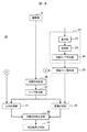
図10は、図8に示した実施例であるエレベーターの長尺物引掛り検出装置が実行する画像処理を示すフローチャートである。
As another method of measuring the distance by the
[Description of operation]
FIG. 10 is a flowchart showing image processing executed by the elevator long object catch detection apparatus according to the embodiment shown in FIG.
まず、処理の開始直後に前処理を実行する(ステップs1)。これは演算処理に必要なメモリを初期化したり、上述した領域マップを保存元から読み出してメモリに格納したりする処理が含まれる。次に、撮像部5により昇降路内の画像を取得し(ステップs2)、取得する度にステップs8までの一連の処理を実行する。ステップs8では終了割込みの有無をチェックし、割込みがあった時は一連の処理を終了する。一方、終了割込みの無い時は、ステップs2に戻り、再び画像を取得して、ステップs2以降の処理を繰り返す。 First, preprocessing is executed immediately after the start of processing (step s1). This includes a process of initializing a memory necessary for arithmetic processing and reading the above-described area map from a storage source and storing it in the memory. Next, an image in the hoistway is acquired by the imaging unit 5 (step s2), and a series of processing up to step s8 is executed each time it is acquired. In step s8, it is checked whether or not there is an end interrupt, and when there is an interrupt, a series of processing ends. On the other hand, when there is no end interruption, the process returns to step s2, and an image is acquired again, and the processes after step s2 are repeated.
画像取得後は時間平均化処理を実行する(ステップs3)。次にロープ検出処理を実行する(ステップs4)。そして検出したロープ画像に基づいて、ロープが向かう方向、およびロープと遮蔽板の距離の両方あるいはどちらか一方を計測する(ステップs5)。次に、ステップs5で計測されたロープの方向と距離から引掛りの有無を判定する(ステップs6)。そして、ステップs6における判定結果を出力する(ステップs7)。 After the image acquisition, a time averaging process is executed (step s3). Next, a rope detection process is executed (step s4). Based on the detected rope image, the direction of the rope and / or the distance between the rope and the shielding plate are measured (step s5). Next, it is determined whether or not there is a catch from the direction and distance of the rope measured in step s5 (step s6). Then, the determination result in step s6 is output (step s7).
なお、ステップs2〜s7の個々の処理を実行するための具体的手段については、上述した構成例の通りである。
[設定ツール]
次に、図8に示した設定ツール21による領域マップの作成について説明する。設定ツール21は、例えば、パーソナルコンピュータなどによって構成する。
Note that specific means for executing the individual processes of steps s2 to s7 are as described in the configuration example described above.
[Setting Tool]
Next, creation of an area map by the
まず、撮像部5によって取得した画像を入力して、表示部22、例えばディスプレイ装置に表示する。次に、指示部23、例えばポインティングデバイスにより、表示部22上、例えばディスプレイ装置の画面上で必要事項を指示する。例えば、図11は、撮像部5−1(図2参照)で撮影した画像例であるが、壁同士の交線や、建物柱33,34などの重力の方向に延びる線分を、これら交線や線分上の2点以上を指示部23で指示することにより設定する。この場合、例えば、指示点35,36の組、指示点37,38の組が指示される。これにより、指示点35ないし38の座標が領域マップ作成部24に入力されて、線分33と線分34の交点の座標が消失点39として算出される。この消失点に向かう方向が、入力画像において重力に従ってロープが垂れる方向である。次に、遮蔽板2の座標と、距離円2−5Rの中心および半径とを、指示部23で設定する。必要に応じて、画像処理の対象領域として壁1−Rの領域を指定する。
First, an image acquired by the
図12は、撮像部5−2で撮影した画像例を示し、指示点40ないし43に基づいて、消失点44が設定される。
FIG. 12 shows an example of an image taken by the imaging unit 5-2, and the vanishing
なお、図5に示したような撮像部5−3で撮影した場合の画像については、消失点を求める必要は無く、遮蔽板の位置と距離円を設定する。 In addition, about the image at the time of image | photographing with the imaging part 5-3 as shown in FIG. 5, it is not necessary to obtain | require a vanishing point, and the position and distance circle of a shielding board are set.
以上で説明した、本発明の第一の実施例であるエレベーターの長尺物引掛り検出装置によれば、撮像部5の設置されている階床の遮蔽板へのロープの引掛りのある場合、並びにその階床の上層階床または下層階床における引掛りの有無を確実に判定することができる。
According to the elevator long object catch detection device according to the first embodiment of the present invention described above, when the rope is hooked to the shielding plate on the floor where the
図13は、本発明の第二の実施例であるエレベーターの長尺物引掛り検出装置を示すブロック図である。 FIG. 13 is a block diagram showing a long object catch detection apparatus for an elevator according to a second embodiment of the present invention.
本実施例は、本図に示す長尺物引掛り検出部20−1,20−2,…,20−n(nは2以上の整数)として、図8に示したエレベーターの長尺物引掛り検出装置20を複数備える。長尺物引掛り検出部20−1,20−2,…,20−nが備える各撮像部は、それぞれ異なる階床の遮蔽板2を視野内に納めるように設置される(図2参照)。長尺物引掛り検出部20−1,20−2,…,20−nの各出力すなわちロープ引掛りの有無の判定結果は、総合判定部48で統合されてエレベーター自動復旧装置49に入力される。また、振動センサ45の出力が起動部46に入力されると、起動部46は長尺物引掛り検出部20−1,20−2,…,20−nおよび乗りかご停止階床判定部47を起動する。
In this embodiment, the long object catch detection units 20-1, 20-2,..., 20-n (n is an integer of 2 or more) shown in this figure are used to catch the long object of the elevator shown in FIG. A plurality of
まず、振動センサ45は、地震等で建物に所定の揺れを検出した場合にエレベーターを停止させるための原信号を出力する。この時、乗りかご停止階床判定部47は乗りかごの停止階床を検知している。振動センサ45が建物の揺れが収束したことを検出すると、起動部46は、長尺物引掛り検出部20−1,20−2,…,20−nを起動させ、ロープ引掛りの有無を総合判定部48に出力させる。これと共に、乗りかご停止階床判定部47は総合判定部48に乗りかごの停止階床を通知する。総合判定部48は、乗りかご停止階床判定部47から通知された階床を除いて、各階床の長尺物引掛り検出部が出力するロープ引掛り検出判定結果の論理和を演算し、この論理和によってロープ引掛りの無いことを判定した場合(すなわち、論理和の演算に用いた全ての長尺物引掛り検出部20−1,20−2,…,20−nでロープ引掛かりの無いことを示している場合)に、エレベーター自動復旧装置49を起動する。エレベーター自動復旧装置49は、自動診断運転を実行し、エレベーターに異常がないことが確認されたら、エレベーターをサービス運転できる状態に自動復旧する。なお、自動復旧後は、保守員による確認作業が実施されるまで、通常のサービス運転時よりも低速で運転しても良い。
First, the
第一の実施例について前述したように、エレベーターの長尺物引掛り検出装置は、その撮像部が設置されている階床の遮蔽板へのロープ引掛りがある場合に加えて、その上層階床または下層階床における引掛りの有無も判定することができる。従って、各階床毎に長尺物引掛り検出部を設置せずとも、建物全体についてのロープの引掛りの有無を検出することができる。例えば、一ないし数階床おきに、長尺物引掛り検出部を設置することができる。また、乗りかごが停止している階床における長尺部引掛り検出部の判定結果は、総合判定部48が論理和を演算する判定結果には含めないため、乗りかごの影響による誤検出を抑制できる。
As described above with respect to the first embodiment, the long object catch detection device for an elevator has an upper floor in addition to the case where there is a rope hook to the shielding plate of the floor where the imaging unit is installed. The presence or absence of catching on the floor or lower floor can also be determined. Therefore, it is possible to detect the presence or absence of rope hooking for the entire building without installing a long object hook detection unit for each floor. For example, a long object catch detector can be installed every other floor. In addition, the determination result of the long-part hook detection unit in the floor where the car is stopped is not included in the determination result of the OR operation performed by the
図14は、本発明の第三の実施例であるエレベーターの長尺物引掛り検出装置を示すブロック図である。 FIG. 14: is a block diagram which shows the elongate object catch detection apparatus of the elevator which is the 3rd Example of this invention.
本実施例のエレベーターの長尺物引掛り検出装置50は、撮像部5と、3次元距離センサ51と、設定ツール21と、領域マップ保持部25と、時間平均化部26と、ロープ検出部27と、方向計測部28と、距離計測部29と、引掛り有無判定部30と判定結果出力部31を備える。なお、図8のエレベーターの長尺物引掛り検出装置20の処理ブロックと同一の符号のブロックの処理機能は、エレベーターの長尺物引掛り検出装置50においても同様である。
The elevator long object
3次元距離センサ51は、ステレオカメラやTime of Flight(TOF)カメラなど、奥行き方向の距離を検出できる機器を適用することができる。3次元距離センサ51は、領域マップ(A)に含まれる遮蔽板と3次元距離センサ51との間の3次元的距離を計測すると共に、この遮蔽板から所定の3次元的距離以内、例えば3次元的に約1m以内に存在する昇降路内の物体を検出して、領域マップ保持部25から読み出された領域マップ(A)に重畳する。そして、3次元距離センサ51は、領域マップ(A)において、重畳された領域以外の領域、すなわち遮蔽板から所定3次元的距離以内に検出された物体が位置する3次元的領域以外の部分に該当する画像上の領域に対し、無効領域としてマスキング処理を施す。領域マップ(A)は、マスキング処理を施された後、領域マップ(B)として3次元距離センサ51から出力される。ここで、撮像部5と3次元距離センサ51の設置位置の差異により、両者の画角が異なる。そこで、両画角のずれ量を予め3次元距離センサ51に登録し、3次元距離センサ51は、このずれ量に基づいて、遮蔽板から所定の3次元的距離以内に検出された物体の位置を、領域マップ(A)における位置に補正する。そして、方向計測部28および距離計測部29は、領域マップ(B)を用いて、3次元距離センサ51によって検出された物体が位置する画像上の領域のみについて突起物と長尺物との距離、もしくは方向を計測する。
As the three-
本実施例によれば、遮蔽板から所定距離以内、例えば1メートル以内に接近したロープのみが引掛り検出の対象となるので、誤検出あるいは誤報を抑制することができる。 According to the present embodiment, since only the rope that is within a predetermined distance from the shielding plate, for example, within 1 meter, is the target of the hook detection, it is possible to suppress false detection or false alarm.
なお、本発明は前述した各実施例に限定されるものではなく、様々な変形例が含まれる。例えば、前述した各実施例は本発明を分かりやすく説明するために詳細に説明したものであり、必ずしも説明した全ての構成を備えるものに限定されるものではない。また、ある実施例の構成の一部を他の実施例の構成に置き換えることが可能であり、さらに、ある実施例の構成に他の実形例の構成を加えることも可能である。さらにまた、各実施例の構成の一部について、他の構成の追加・削除・置き換えをすることが可能である。 In addition, this invention is not limited to each Example mentioned above, Various modifications are included. For example, each of the above-described embodiments has been described in detail in order to explain the present invention in an easy-to-understand manner, and is not necessarily limited to one having all the configurations described. Further, a part of the configuration of one embodiment can be replaced with the configuration of another embodiment, and further, the configuration of another actual example can be added to the configuration of one embodiment. Furthermore, it is possible to add, delete, or replace other configurations for a part of the configuration of each embodiment.
例えば、上記各実施例は、主ロープ,コンペンロープや,ガバナロープなどのロープのほか、コンペンチェーン,テールコードや制御ケーブルなどを含む長尺物の引掛りの検出に適用することができる。この場合、図15に示したロープの起点に代えて制御ケーブルの起点を考慮する。また、これら長尺物が引掛る突起物としては、遮蔽板のほか、エレベーター機器を昇降路内に固定するためのブラケット類などでも良い。なお、図1におけるロープ起点Sは、図15に図示したもののほか、ロープ止めであっても良い。さらに、図8,14の実施例は、方向計測部28および距離計測部29のどちらか一方のみを備えるものでも良い。
For example, each of the embodiments described above can be applied to the detection of the catch of a long object including a main rope, a compensation rope, a rope such as a governor rope, and a compensation chain, a tail cord, a control cable, and the like. In this case, the starting point of the control cable is considered instead of the starting point of the rope shown in FIG. Moreover, as a protrusion which these long objects catch, brackets etc. for fixing an elevator apparatus in a hoistway other than a shielding board may be sufficient. Note that the rope starting point S in FIG. 1 may be a rope stopper other than the one shown in FIG. Further, the embodiment of FIGS. 8 and 14 may include only one of the
1…昇降路
1−B,1−C,1−L,1−R…昇降路壁
2,2−1,2−2,2−3,2−4,2−5,2−6,2−7…遮蔽板
2−5R…距離円
3,6,7,8,11,14…ロープ(引掛り無し)
4,9A,9B,10,12A,12B,13,15A,15B,16,17…ロープ(引掛りあり)
5,5−1,5−2,5−3,5−4…撮像部
F1,F2,F3,F4…階床の境目
20,50…エレベーターの長尺物引掛り検出装置
21…設定ツール
22…表示部
23…指示部
24…領域マップ作成部
25…領域マップ保持部
26…時間平均化部
27…ロープ検出部
28…方向計測部
29…距離計測部
30…引掛り有無判定部
31…判定結果出力部
32…サークルテンプレート
33,34…建物柱
35,36,37,38,40,41,42,43…指示点
39,44…消失点
45…振動センサ
46…起動部
47…乗りかご停止階床判定部
48…総合判定部
49…エレベーター自動復旧装置
51…3次元距離センサ
100…乗場ドア
101…巻上機設置床
102…制御ケーブル
103…制御ケーブル102の起点
104…主ロープ
105…主ロープ104の起点
106…主ロープ104の起点
107…ガバナロープ
108…プーリ
109…ガバナロープ107の起点
110…ガバナロープ107の起点
111…コンペンロープ
112…乗りかご
113…コンペンロープ111の起点
114…錘
115…コンペンロープ111の起点
DESCRIPTION OF
4, 9A, 9B, 10, 12A, 12B, 13, 15A, 15B, 16, 17 ... Rope (with hook)
5, 5-1, 5-2, 5-3, 5-4 ... imaging units F1, F2, F3, F4 ...
Claims (9)
前記画像を取得する撮像部と、
前記撮像部が取得した前記画像に基づいて、前記突起物と前記長尺物との距離、もしくは前記長尺物が向かう方向を計測する計測部と、
前記計測部が計測した前記距離または前記方向に基づいて、前記突起物への前記長尺物の引掛りの有無を判定する判定部と、
を備えることを特徴とするエレベーターの長尺物引掛り検出装置。 In the elevator long object catch detection device for detecting the hook of the long object to the projection in the elevator hoistway by the image in the hoistway,
An imaging unit for acquiring the image;
Based on the image acquired by the imaging unit, a measurement unit that measures a distance between the protrusion and the long object, or a direction in which the long object is directed;
Based on the distance or the direction measured by the measurement unit, a determination unit that determines whether or not the long object is caught on the protrusion,
A long object catch detection device for an elevator, comprising:
前記撮像部は、前記昇降路内において、前記突起物が位置する昇降路壁に設置されることを特徴とするエレベーターの長尺物引掛り検出装置。 In claim 1,
In the hoistway, the image pickup unit is installed on a hoistway wall where the protrusion is located.
前記計測部は、時間平均された前記画像に基づいて前記距離または前記方向を計測することを特徴とするエレベーターの長尺物引掛り検出装置。 In claim 1 or 2,
The said measuring part measures the said distance or the said direction based on the said image averaged over time, The long object catch detection apparatus of the elevator characterized by the above-mentioned.
さらに3次元距離センサを備え、
前記3次元距離センサによって、前記突起物から所定の3次元的距離の範囲内に存在する物体を検出し、
前記計測部は、前記3次元距離センサによって検出された前記物体が位置する画像上の領域のみについて前記突起物と前記長尺物との前記距離、もしくは前記方向を計測することを特徴とするエレベーターの長尺物引掛り検出装置。 In any one of Claims 1 thru | or 3,
In addition, with a three-dimensional distance sensor,
Detecting an object existing within a predetermined three-dimensional distance from the protrusion by the three-dimensional distance sensor;
The said measuring part measures the said distance or the said direction of the said protrusion and the said elongate object only about the area | region on the image where the said object detected by the said three-dimensional distance sensor is located, The elevator characterized by the above-mentioned Long object catch detection device.
前記判定部は、前記突起物と前記長尺物との前記距離が所定の距離内に位置する前記長尺物については引掛り有りと判定することを特徴とするエレベーターの長尺物引掛り検出装置。 In any one of Claims 1 thru | or 4,
The determination unit determines that there is a catch on the long object in which the distance between the protrusion and the long object is within a predetermined distance. apparatus.
前記判定部は、前記長尺物が向かう方向が、前記突起物に向かう方向である場合に、前記長尺物の引掛り有りと判定することを特徴とするエレベーターの長尺物引掛り検出装置。 In any one of Claims 1 thru | or 4,
The determination unit determines that the long object is caught when the direction in which the long object is directed is the direction toward the projection, .
前記突起物の位置、および引掛りの無い前記長尺物が向かう方向が記録された領域マップを予め保持する領域マップ保持部を備え、
前記計測部は、前記領域マップ保持部から前記領域マップを読み出し、読み出した前記領域マップに基づいて、前記突起物と前記長尺物との前記距離、もしくは前記長尺物が向かう前記方向を計測することを特徴とするエレベーターの長尺物引掛り検出装置。 In any one of Claims 1 thru | or 6,
An area map holding unit that holds in advance an area map in which the position of the protrusion and the direction in which the long object without catching is recorded are recorded;
The measurement unit reads the region map from the region map holding unit, and measures the distance between the protrusion and the long object or the direction in which the long object is directed based on the read region map. A long object catch detection device for an elevator.
前記エレベーターが設置される建物に設置される振動センサと、
前記振動センサが前記建物の揺れを検出した場合、前記建物の複数階床において前記長尺物の引掛りの有無を判定する複数の引掛り検出部と、
前記複数の引掛り検出部が出力する複数の判定結果の論理和によって前記長尺物の引掛りの有無を判定する総合判定部と、
を備え、
前記複数の引掛り検出部の各々が、
前記画像を取得する撮像部と、
前記撮像部が取得した前記画像に基づいて、前記突起物と前記長尺物との距離、もしくは前記長尺物が向かう方向を計測する計測部と、
前記計測部が計測した前記距離または前記方向に基づいて、前記突起物への前記長尺物の引掛りの有無を判定する判定部と、
を備えることを特徴とするエレベーターの長尺物引掛り検出装置。 In the elevator long object catch detection device for detecting the hook of the long object to the projection in the elevator hoistway by the image in the hoistway,
A vibration sensor installed in a building where the elevator is installed;
When the vibration sensor detects the shaking of the building, a plurality of hook detection units that determine whether or not the long object is hooked on a plurality of floors of the building;
A comprehensive determination unit that determines whether or not the long object is caught by a logical sum of a plurality of determination results output by the plurality of hook detection units;
With
Each of the plurality of hook detection units,
An imaging unit for acquiring the image;
Based on the image acquired by the imaging unit, a measurement unit that measures a distance between the protrusion and the long object, or a direction in which the long object is directed;
Based on the distance or the direction measured by the measurement unit, a determination unit that determines whether or not the long object is caught on the protrusion,
A long object catch detection device for an elevator, comprising:
前記振動センサが前記建物の揺れの収束を検出し、かつ前記総合判定部が前記長尺物の引掛りが無いと判定した場合に、前記エレベーターを自動復旧するエレベーター自動復旧装置を備えることを特徴とするエレベーターの長尺物引掛り検出装置。 In claim 8,
When the vibration sensor detects the convergence of the shaking of the building and the comprehensive determination unit determines that the long object is not caught, the elevator automatic recovery device is provided that automatically recovers the elevator. Elevator long object catch detection device.
Priority Applications (2)
| Application Number | Priority Date | Filing Date | Title |
|---|---|---|---|
| JP2013215997A JP6205234B2 (en) | 2013-10-17 | 2013-10-17 | Elevator long object catch detection device |
| CN201410406642.1A CN104555634B (en) | 2013-10-17 | 2014-08-18 | The bar hook detection device of elevator |
Applications Claiming Priority (1)
| Application Number | Priority Date | Filing Date | Title |
|---|---|---|---|
| JP2013215997A JP6205234B2 (en) | 2013-10-17 | 2013-10-17 | Elevator long object catch detection device |
Publications (2)
| Publication Number | Publication Date |
|---|---|
| JP2015078043A true JP2015078043A (en) | 2015-04-23 |
| JP6205234B2 JP6205234B2 (en) | 2017-09-27 |
Family
ID=53009860
Family Applications (1)
| Application Number | Title | Priority Date | Filing Date |
|---|---|---|---|
| JP2013215997A Active JP6205234B2 (en) | 2013-10-17 | 2013-10-17 | Elevator long object catch detection device |
Country Status (2)
| Country | Link |
|---|---|
| JP (1) | JP6205234B2 (en) |
| CN (1) | CN104555634B (en) |
Cited By (7)
| Publication number | Priority date | Publication date | Assignee | Title |
|---|---|---|---|---|
| JP2019099376A (en) * | 2017-12-06 | 2019-06-24 | フジテック株式会社 | Rope shaking detection device |
| JP2020063127A (en) * | 2018-10-17 | 2020-04-23 | フジテック株式会社 | Long object hooking detection device |
| WO2022195858A1 (en) * | 2021-03-19 | 2022-09-22 | 三菱電機ビルテクノサービス株式会社 | Elevator device |
| JP7147943B1 (en) * | 2021-09-07 | 2022-10-05 | フジテック株式会社 | elevator system |
| JP7363294B2 (en) | 2019-09-30 | 2023-10-18 | 株式会社タダノ | Rope entanglement detection device |
| WO2023238217A1 (en) * | 2022-06-07 | 2023-12-14 | 三菱電機株式会社 | Long-object inspection device for elevator |
| WO2024057445A1 (en) * | 2022-09-14 | 2024-03-21 | 三菱電機ビルソリューションズ株式会社 | Elevator |
Families Citing this family (2)
| Publication number | Priority date | Publication date | Assignee | Title |
|---|---|---|---|---|
| CN108375414B (en) * | 2018-01-23 | 2020-03-31 | 西安理工大学 | Printing paper tape transverse vibration testing device and testing method |
| JP6744453B1 (en) * | 2019-05-09 | 2020-08-19 | 東芝エレベータ株式会社 | Abnormality diagnosis system |
Citations (6)
| Publication number | Priority date | Publication date | Assignee | Title |
|---|---|---|---|---|
| JPS60132883A (en) * | 1983-12-16 | 1985-07-15 | 三菱電機株式会社 | Monitor device for elevator after earthquake |
| JPH1179589A (en) * | 1997-09-11 | 1999-03-23 | Mitsubishi Denki Bill Techno Service Kk | Abnormality detecting device of main rope of elevator |
| JP2007131360A (en) * | 2005-11-08 | 2007-05-31 | Kajima Corp | Elevator control operation device |
| JP2009166939A (en) * | 2008-01-15 | 2009-07-30 | Mitsubishi Electric Corp | Elevator emergency operation device |
| JP2014005117A (en) * | 2012-06-25 | 2014-01-16 | Mitsubishi Electric Building Techno Service Co Ltd | Device and method for inspecting long object in elevator hoistway |
| JP2015020863A (en) * | 2013-07-19 | 2015-02-02 | 三菱電機ビルテクノサービス株式会社 | Elevator long object inspection device and elevator long object inspection method |
Family Cites Families (6)
| Publication number | Priority date | Publication date | Assignee | Title |
|---|---|---|---|---|
| JPH10258976A (en) * | 1997-03-17 | 1998-09-29 | Toshiba Elevator Kk | Governor rope trouble detecting device for elevator |
| JP4399438B2 (en) * | 2006-06-16 | 2010-01-13 | 株式会社日立製作所 | Elevator equipment |
| JP5183185B2 (en) * | 2007-12-14 | 2013-04-17 | 株式会社日立製作所 | Elevator device and control operation method of elevator |
| JP4675390B2 (en) * | 2008-03-18 | 2011-04-20 | 三菱電機株式会社 | Elevator earthquake recovery equipment |
| CN101811635B (en) * | 2009-02-20 | 2012-09-26 | 三菱电机株式会社 | Rope swing detecting device for the elevator and control method for operation automaticlly recovering after earthquake |
| JP2012017192A (en) * | 2010-07-09 | 2012-01-26 | Mitsubishi Electric Corp | Long article vibration detection device and emergency operation device of elevator |
-
2013
- 2013-10-17 JP JP2013215997A patent/JP6205234B2/en active Active
-
2014
- 2014-08-18 CN CN201410406642.1A patent/CN104555634B/en active Active
Patent Citations (6)
| Publication number | Priority date | Publication date | Assignee | Title |
|---|---|---|---|---|
| JPS60132883A (en) * | 1983-12-16 | 1985-07-15 | 三菱電機株式会社 | Monitor device for elevator after earthquake |
| JPH1179589A (en) * | 1997-09-11 | 1999-03-23 | Mitsubishi Denki Bill Techno Service Kk | Abnormality detecting device of main rope of elevator |
| JP2007131360A (en) * | 2005-11-08 | 2007-05-31 | Kajima Corp | Elevator control operation device |
| JP2009166939A (en) * | 2008-01-15 | 2009-07-30 | Mitsubishi Electric Corp | Elevator emergency operation device |
| JP2014005117A (en) * | 2012-06-25 | 2014-01-16 | Mitsubishi Electric Building Techno Service Co Ltd | Device and method for inspecting long object in elevator hoistway |
| JP2015020863A (en) * | 2013-07-19 | 2015-02-02 | 三菱電機ビルテクノサービス株式会社 | Elevator long object inspection device and elevator long object inspection method |
Cited By (8)
| Publication number | Priority date | Publication date | Assignee | Title |
|---|---|---|---|---|
| JP2019099376A (en) * | 2017-12-06 | 2019-06-24 | フジテック株式会社 | Rope shaking detection device |
| JP2021008366A (en) * | 2017-12-06 | 2021-01-28 | フジテック株式会社 | Rope shaking detection device |
| JP2020063127A (en) * | 2018-10-17 | 2020-04-23 | フジテック株式会社 | Long object hooking detection device |
| JP7363294B2 (en) | 2019-09-30 | 2023-10-18 | 株式会社タダノ | Rope entanglement detection device |
| WO2022195858A1 (en) * | 2021-03-19 | 2022-09-22 | 三菱電機ビルテクノサービス株式会社 | Elevator device |
| JP7147943B1 (en) * | 2021-09-07 | 2022-10-05 | フジテック株式会社 | elevator system |
| WO2023238217A1 (en) * | 2022-06-07 | 2023-12-14 | 三菱電機株式会社 | Long-object inspection device for elevator |
| WO2024057445A1 (en) * | 2022-09-14 | 2024-03-21 | 三菱電機ビルソリューションズ株式会社 | Elevator |
Also Published As
| Publication number | Publication date |
|---|---|
| CN104555634B (en) | 2016-09-28 |
| JP6205234B2 (en) | 2017-09-27 |
| CN104555634A (en) | 2015-04-29 |
Similar Documents
| Publication | Publication Date | Title |
|---|---|---|
| JP6205234B2 (en) | Elevator long object catch detection device | |
| JP5514234B2 (en) | Elevator speed measuring device, elevator | |
| CN107314807B (en) | A kind of method of wirerope horizontal space vibration measurement | |
| JP6329304B1 (en) | Rope inspection equipment | |
| CN107487676A (en) | Detection and control system for elevator operation | |
| JP5224933B2 (en) | Elevator restoration operation method and apparatus | |
| JP6132690B2 (en) | Elevator long object inspection device and elevator long object inspection method | |
| JP6778648B2 (en) | Elevator device and control method of elevator device | |
| JP2009012903A (en) | Device and method for inspecting component strand disconnection of elevator wire rope | |
| KR20210013287A (en) | Inspection device with the function of presenting the internal condition of the elevator hoistway | |
| JP6835026B2 (en) | Rope runout detector | |
| JP6699179B2 (en) | Image processing device | |
| JP6784285B2 (en) | Long object catching detector | |
| EP3650390A1 (en) | Conveyance system video analytics | |
| JP7167994B2 (en) | An inspection device and inspection system capable of inspecting the inside of an elevator hoistway | |
| JP4561266B2 (en) | Falling object detector | |
| JP6737254B2 (en) | Information processing equipment | |
| JP6900965B2 (en) | Long object runout detector | |
| WO2023238217A1 (en) | Long-object inspection device for elevator | |
| JP2015168272A (en) | Gap falling detection system | |
| JP7147943B1 (en) | elevator system | |
| JP2013203484A (en) | Passenger conveyor | |
| JP2023178558A (en) | Elevator rope inspection system and elevator rope inspection method | |
| JPS60157479A (en) | Monitor device for elevator | |
| CN110937481B (en) | Water detection inside elevator pit |
Legal Events
| Date | Code | Title | Description |
|---|---|---|---|
| A621 | Written request for application examination |
Free format text: JAPANESE INTERMEDIATE CODE: A621 Effective date: 20160713 |
|
| A977 | Report on retrieval |
Free format text: JAPANESE INTERMEDIATE CODE: A971007 Effective date: 20170428 |
|
| A131 | Notification of reasons for refusal |
Free format text: JAPANESE INTERMEDIATE CODE: A131 Effective date: 20170509 |
|
| A521 | Request for written amendment filed |
Free format text: JAPANESE INTERMEDIATE CODE: A523 Effective date: 20170703 |
|
| TRDD | Decision of grant or rejection written | ||
| A01 | Written decision to grant a patent or to grant a registration (utility model) |
Free format text: JAPANESE INTERMEDIATE CODE: A01 Effective date: 20170822 |
|
| A61 | First payment of annual fees (during grant procedure) |
Free format text: JAPANESE INTERMEDIATE CODE: A61 Effective date: 20170904 |
|
| R150 | Certificate of patent or registration of utility model |
Ref document number: 6205234 Country of ref document: JP Free format text: JAPANESE INTERMEDIATE CODE: R150 |