JP2015077669A - Cutting tool holder and cutting tool - Google Patents
Cutting tool holder and cutting tool Download PDFInfo
- Publication number
- JP2015077669A JP2015077669A JP2013217676A JP2013217676A JP2015077669A JP 2015077669 A JP2015077669 A JP 2015077669A JP 2013217676 A JP2013217676 A JP 2013217676A JP 2013217676 A JP2013217676 A JP 2013217676A JP 2015077669 A JP2015077669 A JP 2015077669A
- Authority
- JP
- Japan
- Prior art keywords
- holder
- cutting tool
- shaft hole
- hole
- boring bar
- Prior art date
- Legal status (The legal status is an assumption and is not a legal conclusion. Google has not performed a legal analysis and makes no representation as to the accuracy of the status listed.)
- Pending
Links
Images


Classifications
-
- B—PERFORMING OPERATIONS; TRANSPORTING
- B23—MACHINE TOOLS; METAL-WORKING NOT OTHERWISE PROVIDED FOR
- B23B—TURNING; BORING
- B23B31/00—Chucks; Expansion mandrels; Adaptations thereof for remote control
- B23B31/02—Chucks
- B23B31/10—Chucks characterised by the retaining or gripping devices or their immediate operating means
- B23B31/107—Retention by laterally-acting detents, e.g. pins, screws, wedges; Retention by loose elements, e.g. balls
- B23B31/1075—Retention by screws
-
- B—PERFORMING OPERATIONS; TRANSPORTING
- B23—MACHINE TOOLS; METAL-WORKING NOT OTHERWISE PROVIDED FOR
- B23B—TURNING; BORING
- B23B27/00—Tools for turning or boring machines; Tools of a similar kind in general; Accessories therefor
- B23B27/007—Tools for turning or boring machines; Tools of a similar kind in general; Accessories therefor for internal turning
-
- B—PERFORMING OPERATIONS; TRANSPORTING
- B23—MACHINE TOOLS; METAL-WORKING NOT OTHERWISE PROVIDED FOR
- B23B—TURNING; BORING
- B23B27/00—Tools for turning or boring machines; Tools of a similar kind in general; Accessories therefor
- B23B27/10—Cutting tools with special provision for cooling
-
- B—PERFORMING OPERATIONS; TRANSPORTING
- B23—MACHINE TOOLS; METAL-WORKING NOT OTHERWISE PROVIDED FOR
- B23B—TURNING; BORING
- B23B29/00—Holders for non-rotary cutting tools; Boring bars or boring heads; Accessories for tool holders
- B23B29/04—Tool holders for a single cutting tool
-
- B—PERFORMING OPERATIONS; TRANSPORTING
- B23—MACHINE TOOLS; METAL-WORKING NOT OTHERWISE PROVIDED FOR
- B23B—TURNING; BORING
- B23B2231/00—Details of chucks, toolholder shanks or tool shanks
- B23B2231/24—Cooling or lubrication means
-
- B—PERFORMING OPERATIONS; TRANSPORTING
- B23—MACHINE TOOLS; METAL-WORKING NOT OTHERWISE PROVIDED FOR
- B23B—TURNING; BORING
- B23B2250/00—Compensating adverse effects during turning, boring or drilling
- B23B2250/12—Cooling and lubrication
Abstract
Description
本発明は、旋削等による内径加工に使用される軸穴付きの切削工具用ホルダ、及びこの切削工具用ホルダの軸穴にボーリングバー(一端又は両端の一側に切れ刃が形成された棒状の切削工具)を差し込んで、切削工具用ホルダ自身の外周面から軸穴に向けて貫通して設けられた固定用のネジ穴に止ネジをねじ込むことによって、そのボーリングバーを固定(クランプ)してなる切削工具に関する。 The present invention relates to a cutting tool holder with a shaft hole used for inner diameter processing by turning or the like, and a boring bar (a rod-like shape having a cutting edge formed at one end or one side of both ends in the shaft hole of the cutting tool holder. The boring bar is fixed (clamped) by inserting a cutting tool into the fixing screw hole that penetrates from the outer peripheral surface of the cutting tool holder itself toward the shaft hole. It relates to a cutting tool.
従来、工作物(被削物)の内径加工(穴加工)のうち、下穴の内周面を旋削等により加工するボーリングにおいては、スリーブ状をなすホルダの軸穴に、先端の一側に切れ刃(刃先)を有するボーリングバーを、その後端から差し込み、これを、切削工具用ホルダ(以下、単にホルダともいう)の外周面に設けられたネジ穴に止ねじをねじ込むことによって固定してなる切削工具が用いられることがある。このような切削工具は、旋盤の刃物台に設けられた、主軸(回転軸)方向に延びるホルダ取付け穴に差し込まれ、そのホルダを、刃物台の外周面に設けられたネジ穴に固定用ボルトをねじ込んで固定され、その加工に用いられる。このような切削工具においては、加工する穴径が小さく、ボーリングバーが細い場合には、クーラントを外部からの供給ではなく、流路を、ホルダ自体に、その軸穴が延びる方向に沿って設けておき、この流路をホルダの先端面において開口させて噴出口(吐出し口)としているものがある(特許文献1)。図11に示したように、この切削工具400では、その噴出口120が、ホルダ500の軸穴110に差し込まれて固定されるボーリングバー200の切れ刃203側(逃げ面側)に位置するように設けられており、クーラント(破線図示)Cを高圧でこの噴出口120からジェット流状に噴出(噴射)させて切れ刃203に浴びせる(吹き付ける)ようになっている。なお、本願においてクーラントは、切れ刃(刃先)203と被削物と間の潤滑、その両者の冷却(温度上昇防止)などを目的として切削箇所に浴びせられる流体(切削液やガス)を意味する。
Conventionally, in boring in which the inner peripheral surface of a prepared hole is machined by turning or the like among the inner diameter machining (hole machining) of a workpiece (workpiece), the shaft hole of the sleeve-shaped holder is placed on one side of the tip. A boring bar having a cutting edge (cutting edge) is inserted from the rear end thereof, and this is fixed by screwing a set screw into a screw hole provided on the outer peripheral surface of a cutting tool holder (hereinafter also simply referred to as a holder). A cutting tool may be used. Such a cutting tool is inserted into a holder mounting hole provided in a tool post of a lathe and extending in a main shaft (rotating axis) direction, and the holder is fixed to a screw hole provided in an outer peripheral surface of the tool post. Is used for processing. In such a cutting tool, when the hole diameter to be machined is small and the boring bar is thin, the coolant is not supplied from the outside, but the flow path is provided in the holder itself along the direction in which the axial hole extends. In some cases, this flow path is opened at the front end surface of the holder to form a jet outlet (discharge outlet) (Patent Document 1). As shown in FIG. 11, in this
このような切削工具400による穴の内径(内周面)加工においては、その内径が小径(例えば、φ10mm)である場合には、ボーリングバー200の太さ確保の要請から、同バーの外周面と穴の内周面と隙間が小さくなるため、切り屑の排出性が悪くなる。それでも、図12に示したように、工作物Wの穴が貫通している場合の加工においては、ホルダ500の先端の噴出口120からのクーラントCの噴出により、その切れ刃203において発生する切り屑は、クーラントCと共にその穴の奥の開口から排出させることができる。ところが、小径の穴が貫通穴でなく、ボーリングバーの進入開始(入口)側と反対側の端部が閉口している、いわゆる止まり穴(奥が閉じた穴)におけるその内径加工においては、このような排出は得られない。このため、このような止まり穴の加工の場合においては、貫通穴の加工の場合に比べると、切り屑の排出性は極端に低下し、穴の奥に滞留しがちとなることから、その内周面を傷付け、仕上げ面粗度の低下を招くなどの問題を発生させる。
In such an inner diameter (inner peripheral surface) processing of a hole by the
こうした中、このような止まり穴の内径加工においても、切り屑の排出性を高められるように、クーラントの噴出口を、切削工具を先端側から見たとき(工作物の回転軸方向から見たとき)において、切れ刃側(逃げ面)ではなく、その切れ刃と反対側(背面側)に開口させるようにした発明が知られている(特許文献2)。このものでは、図13に示したように、クーラントCを切れ刃203と反対側に設けられた噴出口120から、止まり穴の奥に向けて噴出させて、いわば穴の奥でUターンさせるようにして回収することで、切れ刃203側において発生する切り屑を、その切れ刃203側に設けられた切り屑排出溝等の空隙に沿わせてクーラントCと共に、その止まり穴の入口側に排出させるというものである。以下、図11、図12に示したように、切れ刃203側においてクーラントを供給するその供給方式を「刃先供給」ともいい、図13に示したように、切れ刃203と反対側においてクーラントを供給するその供給方式を「背面供給」ともいう。
Under such circumstances, the coolant outlet is seen from the tip side of the cutting tool (viewed from the direction of the rotation axis of the work piece) so that the chip discharge performance can be improved even in the inner diameter machining of such a blind hole. In other words, there is known an invention in which an opening is made not on the cutting edge side (flank face) but on the side opposite to the cutting edge (back face side) (Patent Document 2). In this case, as shown in FIG. 13, the coolant C is ejected from the
ところで、このような背面供給(方式)を、図11に示したホルダ500と、その軸穴110に差し込まれて固定されてなるボーリングバー200とからなる切削工具400において実現するには、次のようになる。すなわち、刃先供給により、貫通穴の内径加工を行っていた切削工具400は、それを先端から見たとき、図14−Aに示したように、ホルダ500の先端面103において開口するクーラントの噴出口120は、ボーリングバー200の切れ刃203側に位置する。そして、この切削工具400において、止まり穴の内径加工のため、背面供給へ変更する段取り作業においては、図14−Aにおいて、切削工具400が旋盤の刃物台Hに固定されているとすると、そのホルダ500を固定している刃物台Hにおける固定ボルトVoと、ホルダ500にボーリングバー200を固定している止めネジ130を、それぞれ緩め、そして、例えば、軸穴110内においてボーリングバー200は回転させることなく、ホルダ500のみを刃物台Hの取付け穴内で反転(180度回転)させ、固定ボルトVo及び止ネジ130をねじ込む。これにより、図14−Bに示したように、ホルダ500の先端面において開口するクーラントの噴出口120は、ボーリングバー200の切れ刃203と反対側に位置することになり、背面供給による加工が可能となる。
By the way, in order to realize such a back surface supply (method) in the
一方、上記従来の切削工具400をなすホルダ500において、ボーリングバー200を固定するための止ネジ130をねじ込むネジ穴135は、ボーリングバー200のシャンク部をなす外周面の一側面に設けられる(図11、図12参照)。そして、この止ネジ130によるボーリングバー200の固定のための押さえつけは、その切れ刃203のすくい面205を向くのと同向き面において行われる。このような押え付け状態としておけば、切削抵抗の主分力が、止ネジ130の先端による点支持による受圧でなく、軸穴110の内周面で受圧できるから、その切れ刃203の高い安定が得られるためである。他方、上記従来の切削工具400においては、刃先供給が原則とされているため、ボーリングバー200の押さえつけ面は、その切れ刃203のすくい面205を向くのと同向き面とされ、したがって、その止ネジ130をねじ込む穴は、刃先供給において切れ刃203のすくい面205を向くのと同向き面側に設けられている。
On the other hand, in the
上記したことから明らかなように、この切削工具400において、背面供給にするため、ボーリングバー200に対し、ホルダ500を回転させる場合には、図14−Bに示したように、その止ネジ130は、ボーリングバー200の切れ刃203のすくい面205と同向き面ではなく、これと反対向き面の押さえつけることになる。このため、このような固定における切削では、切削抵抗の主分力を止ネジ130の先端で受圧することになり、不適切な固定状態になるという問題があった。
As is apparent from the above description, when the
しかも、本来、このような止ネジ130等のねじ込み作業を含むその段取り作業においては、作業者が、その止ネジ130等が目視できるように、ホルダ500の上面側からの見下ろしによるねじ込み作業となるように刃物台Hに固定される設定とされる。一方、上記したように背面供給に変更する際には、ホルダ500を刃物台Hの取付け穴において180度回転することから、この止ネジ130のねじ込み作業は、ホルダ500の下面からのねじ込み作業となってしまう。したがって、その作業性が悪くなるという問題もある。なお、ホルダ500を回転させることなく、ボーリングバー200を180度回転させて、これ逆向きに配置する(いわゆる逆バイトにする)ことで内径加工をすることにすれば、このようなねじ込み作業上の問題はなくなる。しかし、その場合にも、止ネジ130は、すくい面205側と反対向き面を押さえつけることになるから、不適切な固定となる。その上、逆バイトにする場合には、切れ刃203の刃先位置等の位置に相違が生じるから、例えば、NC旋盤では、プログラムを別に作成しておく必要がある上に、その設定を変更する必要があるという問題もある。
Moreover, originally, in the setup work including the screwing work of the
こうしたことから、従来は、「刃先供給」と「背面供給」とのいずれにおいても、止ネジ130によるボーリングバー200の押さえつけが、その切れ刃203のすくい面205を向くのと同向き面で行い得るように、クーラントの噴出口120の位置ごと、ネジ穴135の位置が異なる2種類のホルダを取り揃えておく必要があった。このため、ホルダの数が倍加するため、この種の機械加工の現場では、切削工具の在庫及びその管理上において著しい難点があり、かつ、加工コストの増大を招く原因ともなっていた。
For this reason, conventionally, in both “blade edge supply” and “back surface supply”, pressing of the
本発明は、上記した内径加工用の切削工具における問題点に鑑みてなされたもので、ボーリングバーの固定における問題点を発生させることなく、しかも、クーラントの刃先供給と背面供給といった噴出口の位置の違いにも、1つのホルダで対応できるようにすることをその目的とする。 The present invention has been made in view of the above-described problems in the cutting tool for machining the inner diameter, and does not cause problems in fixing the boring bar, and the position of the jet outlet such as the coolant blade tip supply and the back surface supply. It is an object of the present invention to be able to cope with the difference in one with one holder.
請求項1に記載の発明は、先端の一側に切れ刃を有するボーリングバーを差込し込み得る軸穴と、差し込まれたボーリングバーを、止ネジをねじ込むことによって固定するための1又は複数のネジ穴が自身の外周面の一側に、前記軸穴に向けて貫通して設けられてなる切削工具用ホルダであって、
前記軸穴に差し込まれて前記止ネジのねじ込みによって固定される前記ボーリングバーの先端に向けてクーラントを噴出させ得るように形成された噴出口が、自身の先端面において開口されてなる切削工具用ホルダにおいて、
前記軸穴の径方向における前記ネジ穴と反対側にも、差し込まれたボーリングバーを止ネジをねじ込むことによって固定するためのネジ穴が、自身の外周面から前記軸穴に向けて貫通して設けられてなることを特徴とする。
The invention according to
For a cutting tool in which a jet port formed so that coolant can be jetted toward the tip of the boring bar that is inserted into the shaft hole and fixed by screwing the set screw is opened at the tip surface of the cutting tool In the holder,
On the opposite side to the screw hole in the radial direction of the shaft hole, a screw hole for fixing the inserted boring bar by screwing a set screw penetrates from its outer peripheral surface toward the shaft hole. It is characterized by being provided.
請求項2に記載の発明は、前記切削工具用ホルダを先端面から見たとき、前記噴出口が、前記ネジ穴の中心線に垂直であって、前記軸穴の中心を通るように引いた直線上に存在するように設けられていることを特徴とする請求項1に記載の切削工具用ホルダである。
請求項3に記載の発明は、前記切削工具用ホルダを先端面から見たとき、前記噴出口が、前記ネジ穴の中心線に垂直であって、前記軸穴の中心を通るように引いた直線上に存在しないように設けられていることを特徴とする請求項1に記載の切削工具用ホルダである。
請求項4に記載の発明は、前記噴出口は、前記先端面のうち、前記軸穴の内周面において凹設されて開口されていることを特徴とする請求項1〜3のいずれか1項に記載の切削工具用ホルダである。
According to a second aspect of the present invention, when the cutting tool holder is viewed from the front end surface, the ejection port is pulled so as to be perpendicular to the center line of the screw hole and pass through the center of the shaft hole. It is provided so that it may exist on a straight line, The holder for cutting tools of
According to a third aspect of the present invention, when the cutting tool holder is viewed from the front end surface, the ejection port is drawn so as to be perpendicular to the center line of the screw hole and pass through the center of the shaft hole. It is provided so that it may not exist on a straight line, The holder for cutting tools of
The invention according to
請求項5に記載の発明は、前記噴出口は、前記切削工具用ホルダ内に、前記軸穴とは連通することなく設けられた流路を介して、前記先端面のうち、該軸穴の近傍において独立した穴として開口されていることを特徴とする請求項1〜3のいずれか1項に記載の切削工具用ホルダである。
請求項6に記載の発明は、前記ネジ穴には、そのすべてに前記止ネジが螺合されていることを特徴とする請求項1〜5のいずれか1項に記載の切削工具用ホルダである。
請求項7に記載の発明は、請求項6に記載の切削工具用ホルダの前記軸穴に、前記ボーリングバーが差し込まれ、このボーリングバーが、前記止ネジのうち、そのすくい面と同向き面を押さえつける位置にあるネジ穴に螺合されている止ネジのねじ込みによって固定されてなる切削工具である。
According to a fifth aspect of the present invention, the spout is formed in the shaft hole of the tip surface through a flow path provided in the cutting tool holder without communicating with the shaft hole. The cutting tool holder according to any one of
The invention according to claim 6 is the cutting tool holder according to any one of
According to a seventh aspect of the present invention, the boring bar is inserted into the shaft hole of the cutting tool holder according to the sixth aspect, and the boring bar is a surface in the same direction as the rake face of the set screw. This is a cutting tool fixed by screwing a set screw screwed into a screw hole at a position to press down.
本発明に係る切削工具用ホルダによれば、上記構成により、その構造の格別の複雑化を招くこともなく、刃先供給と背面供給とのいずれにおいても、止ネジによるボーリングバーの固定のための押さえつけを、その切れ刃のすくい面が向く向きと同向き面で行い得る。このため、従来のように、クーラントの噴出口の位置の勝手違い対応できるように、ネジ穴の位置が異なる2種類のホルダを取り揃えておく必要がなくなり、したがって、切削工具の在庫及びその管理上における効果には著しいメリットが得られる。このように本発明に係るホルダによれば、上記構成により、ボーリングバーの固定のための止ネジのねじ込みによる押え付け上の問題もなく、1つのホルダで、クーラントの刃先供給と背面供給といった噴出口の位置の変更に対応できる便利なホルダとなすことができ、加工コストの低減も図られるという際立って優れた効果が得られる。なお、本発明において、噴出口は、ホルダ自身の先端面において開口されてなるものであるが、刃先供給と背面供給との選択ができればよく、したがって、噴出口自体は、その先端面のうち、軸穴の一側において、1つが開口されていることでも足りるが、複数、開口されていてもよい。 According to the cutting tool holder according to the present invention, the above-described configuration does not cause any special complication of the structure, and for fixing the boring bar with a set screw in both the cutting edge supply and the back surface supply. The pressing can be performed in the same direction as the direction in which the rake face of the cutting edge faces. For this reason, it is not necessary to prepare two types of holders with different screw hole positions so that the position of the coolant outlet can be handled differently as in the prior art. There is a significant merit in the effect of. As described above, according to the holder according to the present invention, with the above-described configuration, there is no problem in press-down due to screwing of a set screw for fixing the boring bar. It is possible to make a convenient holder that can cope with a change in the position of the outlet, and it is possible to obtain a remarkable effect that the processing cost can be reduced. In the present invention, the spout is opened at the front end surface of the holder itself, but it is only necessary to be able to select the blade tip supply and the back surface supply. It is sufficient that one is opened on one side of the shaft hole, but a plurality may be opened.
なお、前記噴出口は、請求項2に記載のように、ホルダを先端面から見たとき、前記ネジ穴の中心線に垂直であって、前記軸穴の中心を通るように引いた直線上のその中心が存在するように設けるのが好ましいが、請求項3に記載のように、前記ホルダを先端面から見たとき、前記噴出口が、前記ネジ穴の中心線に垂直であって、前記軸穴の中心を通るように引いた直線上に存在しないように設けてもよい。 The spout is on a straight line that is perpendicular to the center line of the screw hole and passes through the center of the shaft hole when the holder is viewed from the front end surface. Preferably, the center of the nozzle hole is provided such that when the holder is viewed from the front end surface, the jet port is perpendicular to the center line of the screw hole, You may provide so that it may not exist on the straight line pulled through the center of the said shaft hole.
本発明において、噴出口は、請求項4に記載のように、該軸穴の内周面において凹設したものでもよいし、請求項5に記載のように、該軸穴とは別の独立した穴として設けても良い。請求項4に記載のように設ける場合には、該軸穴の内周面において切り込むように凹設できるため、その形成が容易であるし、穴径が小さく、その内周面とボーリングバーの外周面との隙間が小さい場合にも有効にクーラントを供給できる。一方、このように設ける場合には、その軸穴の内周面と、ボーリングバーの外周面との隙間にクーラントが回り込んだり、止ネジの螺合面を介して漏出する可能性がある等の密閉上の課題がある。これに対して、請求項5に記載の発明では、こうした問題を解消できる。
In the present invention, the jet port may be recessed in the inner peripheral surface of the shaft hole as described in
なお、本発明のホルダにおいては、請求項6に記載の発明のように、 前記ネジ穴には、そのすべてに前記止ネジが螺合されているものとしておくのがよい。というのは、このようにしておけば、止ネジが、散逸したり紛失し難くなるし、切削工具において、刃先供給又は背面供給のいずれにも迅速に対応できるためである。 In the holder of the present invention, as in the invention described in claim 6, it is preferable that the set screw is screwed into all the screw holes. This is because, in this way, the set screw is difficult to dissipate or lose, and the cutting tool can quickly respond to either cutting edge supply or back surface supply.
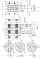
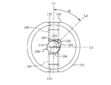
本発明の切削工具用ホルダを具体化した実施の形態例について、図1〜図4に基づいて詳細に説明する。図中、100は、ホルダであって、丸棒(円柱体)において、その中心軸Gに、横断面が円の内周面をなす空孔を同軸で有している。ただし、本例では、この空孔のうち、ホルダ100の先端面103から後端(面)105に向かう途中までが、ボーリングバーを差し込むための軸穴110とされており、その途中から後端105までは、この軸穴110より大径をなすクーラント供給用の流路113とされている。そして、この流路113の内周面のうち、ホルダ100の後端面105に開口する端部には、そのクーラント供給用の配管接続部としてネジ(管用テーパネジ)114が設けられている。
The embodiment which actualized the holder for cutting tools of this invention is described in detail based on FIGS. In the figure,
一方、ホルダ100の外周面102には、一定の幅をなす平面(平坦面)106が、相互に平行に、先後に延びる形で、両側面において同一に形成されている。そして、本例では、この平面106のうち、ホルダ100の先端面103側であって上記した軸穴110に対応する部位に、ホルダ100の直径方向に、軸穴110に向けて貫通する、固定用の止ネジ130をねじ込むためのネジ穴135が設けられている。本例では、各側面において先後に間隔をおいて2箇所の合計4箇所設けられており、各ネジ穴135には、止ネジ130(例えば、六角穴付き止ネジ130)が螺着され得るように設定されている。なお、この平面106は、このホルダ100を含む切削工具を、旋盤の刃物台の取付け穴に挿入した後において、固定用ボルトのねじ込みにより、押え付けられる面である。すなわち、ホルダ100は、旋盤の刃物台における横断面円形の取り付け(空孔)内において摺接状態で回転し得る横断面を有し、かつ、そのホルダ100の固定においてその回転が止められるようにされている。
On the other hand, on the outer
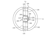
一方、軸穴110は、図4の下図として示したボーリングバー200のように、先後の各端の一側に切れ刃203を有し、その間の中間部位(シャンク部位)207が差し込み得る円形穴とされている。なお、図4に示したボーリングバー200は、先後において相互に反対をなす側面にすくい面205を備えている。軸穴110の内径は、この中間部位207を、その軸線回りに微小な隙間で摺接状態で回転させ得る大きさとされている。本例では、ホルダ100を先端面103側から見たとき(図2参照)、この軸穴110の内周面のうち、止ネジ130のねじ込み用のネジ穴135の軸線(中心線)Lsに垂直であって、軸穴110の中心を通るように引いた直線L1上に凹溝116が凹設されている。そして、この凹溝116は、軸穴110の全長にわたり先後に延びている(図1の各横断面図、及び図3参照)。また、この凹溝116は、ホルダ100を先端面103から見たとき、すなわち、軸穴110の軸線Gに垂直な断面で切断したとき、凹となす円弧状(三日月状)をなしており、その凹溝116の溝幅方向の中心が前記直線L1上に存在するように設けられている。なお、この凹溝116は、その溝幅方向の中心がこの直線L1上に存在していなくともよい。この凹溝116の後端117は後方のクーラント供給用の流路113に連なり、先端はホルダ100の先端面103に開口され、その噴出口120をなすものとされている。
On the other hand, the
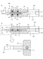
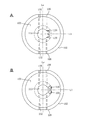
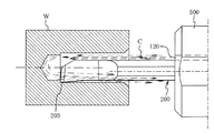
このような本例のホルダ100においては、図4の下図として示したような、軸穴110の径に対応した、所定のボーリングバー200が、その軸穴110に所定量差し込まれる。そして、その中間部位(シャンク部位)207のうち、切れ刃203のすくい面205と同向き面が、ネジ穴135にねじ込まれる止ネジ130にて押さえつけられて、固定される。こうすることで、図5、図6に示した内径加工用の切削工具300となる。この場合において、「刃先供給」の切削工具とする場合には、図6に示したように、ホルダ100の先端面103から見たとき、ボーリングバー200の先端の一側の切れ刃203が、クーラントの噴出口120側となる。このため、この場合には、そのすくい面205が向く面と同向き面側にある止ネジ130(図5−A,図6の上の止ネジ130)を所定トルクでねじ込むことで、クランプすればよい。なお、このねじ込みに先立ち、反対側の止ネジ130は、その先端が軸穴110の内周面に突出しないように、適度に螺退させておけばよい。なお、止ネジ130で固定するボーリングバー200における中間部位207(シャンク部位)には、すくい面205の把握ができ、かつ、回転することなく止ネジ130によるその固定が安定してできるように、すくい面205が向く面と同向き面に、ホルダ100におけるのと同様、所定の幅で先後に延びる平面206がつけられている。因みに、図示のボーリングバー200は、上記したように、先後において相互に異なる側にそれぞれ切れ刃203を有するタイプのものであるから、その平面206は、ホルダ100におけるのと同様、円形断面をベースとして、その外周面の両面に互いに平行に設けられている。
In the
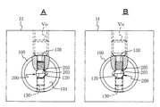
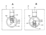
かくして、この切削工具300においては、ホルダ100の後端面105のクーラント供給用の流路113の後端105の接続部(管用ネジ)114にクーラント供給配管を接続して、クーラント(例えば、切削液)を高圧で供給すれば、そのクーラントは、ホルダ100の先端面103において開口する噴出口120から切れ刃203に向けてジェット流となって浴びせられる。これにより、この本例の切削工具300においては、図7−Aに示したように、これを所定の旋盤の刃物台Hの取付け穴にすくい面205を上にして差し込み、固定用ボルトVoで固定することで、「刃先供給」による所望とする内径加工(貫通穴の内径加工)を行うことができる。
Thus, in this
一方、このような本例のホルダ100を用いた切削工具300において、これを、止まり穴の内径加工とするために「背面供給」とする変更を行う段取り時においては、その刃物台Hにおいてホルダ100を固定している固定用ボルトVo、及びホルダ100にねじ込まれている、全ての止ネジ130を螺退して緩め、例えば、ボーリングバー200をそのままの体勢に保持しつつ、ホルダ100をボーリングバー200の周りに反転(180度)する。こうすることで、図7−Bに示したように、噴出口120は「背面供給」の位置に来る。したがって、その位置において、上記したのと同様に止ネジ130をねじ込み、固定用ボルトVoをねじ込むことで、背面供給での内径加工を行うことができる。
On the other hand, in the
すなわち、前記したように、例えば、ボーリングバー200を回転させることなく、ホルダ100をボーリングバー200の軸線回りに反転させることで、クーラントの噴出口120は、切れ刃203側とは反対側に位置する。そして、このとき、ボーリングバー200のすくい面205側にあり、この反転前はその固定の役割を担っていなかった止ネジ130が、反転前においてすくい面205と同向き面において固定していた止ネジ130と同じ位置に来る。したがって、あたかも、反転前に固定の役割を担っていた止ネジ130を、再度、ねじ込むようにすることで、ボーリングバー200の再クランプができる。このように、本例に係るホルダ100によれば、背面供給の使用形態でも、止ネジ130によるボーリングバー200の固定の不安定さを招くこともなく、しかも、そのねじ込み作業も、前と同じ上からの見下ろし姿勢でできるため、作業者にとっても、その作業の簡易迅速化が図られる。当然のことながら、この後、さらに刃先供給へ戻す場合においても全く同様にすることができる。なお、刃先供給と、背面供給との間の変更作業は、勿論、切削工具300を刃物台Hから外して行うこともできるが、その場合においても同様の効果が得られることは明らかである。
That is, as described above, for example, by rotating the
なお、上記例では、噴出口120を軸穴110の内周面において凹設して設け、しかも、その形状を円弧状(三日月形状)のものとしたため、刃先供給と背面供給のいずれにおいても、クーラントをボーリングバー200の先端に向けて、それ沿わせるように、しかも、加工穴の内周面との隙間が小さい場合にも、効率的に供給することができる。ただし、噴出口120を軸穴110の内周面において凹設して設ける(開口する)としても、その流路断面は、円弧状(三日月形状)に限らず、矩形など適宜の断面形状にすることもできる。また、上記例では、ホルダ100の後端面105から、軸穴110と同軸で設けた流路113を介してクーラントを供給する場合で説明したが、クーラントの圧送源(ポンプ)からの供給は、ホルダ100の外周面102のうち、例えば、刃物台への固定に支障のない先端寄り部位に、供給配管の接続口(ねじ込み部)を設けて、噴出口120に連なるように流路113を設けることもできる。
In the above example, the
また、図8に示したように、噴出口120は、ホルダ100の先端面103において、軸穴110と微量でも離間した位置において開口させ、軸穴110とは連通させることなく設けられた流路(図示せず)を介し、独立した穴として設けてもよい。すなわち、この場合には、この噴出口120に連なるように、軸穴110とは別途にクーラント供給用の流路をホルダ100内にトンネル状に形成しておき、クーラントの圧送源からの供給のための接続口を、ホルダ100の後端面105や外周面に設ければよい。このようにすれば、上記もしたように、この噴出口120から、独立のジェット流としてクーラントを噴出させることができるので、例えば、止ネジ130の螺合面(ネジ穴135のネジと止ネジ130のネジとの隙間)などからのクーラントの漏出等の問題を回避できる。加工する穴が小径でも、比較的大きめの穴において有効である。
Further, as shown in FIG. 8, the
上記例の切削工具用ホルダ100は、横断面が円形の丸棒をベースに、外周面に互い平行となる平面106を設けたものとしたが、切削工具用ホルダ100自体の外周面形状は、適宜のものとすることができる。その外周面は、例えば、先端面103に続く先端寄り部位が、それより後方に続く他の部位(刃物台への取付け部)より小径であってもよい。また、軸穴110も、刃先供給か、背面供給かに、ボーリングバーに応じて噴出口120の位置を選択できればよく、したがって、軸穴110の横断面形状も、円に限定されるものではない。
The
さらに、上記例では、ホルダ100を先端面103側から見たときの(図2、図6参照)、噴出口120に連なる凹溝116の溝幅方向の中心が、止ネジ130のねじ込み用のネジ穴135の軸線(中心線)Lsに垂直であって、軸穴110の中心を通るように引いた直線L1上に存在するようにした場合を例示したが、この位置は、次のように変更することもできる。すなわち、上記例では、ホルダ100を先端面103側から見たとき(図2、図6参照)、噴出口120が、ネジ穴135の軸線(中心線)Lsに垂直であって、軸穴110の中心を通るように引いた直線L1上に存在する場合を例示したが、本発明においては、図9に例示したように、噴出口120は、ネジ穴135の軸線(中心線)Lsに垂直であって、軸穴110の中心を通るように引いた直線L1上に存在しないようにしてもよい。
Furthermore, in the above example, when the
図9においては、噴出口120及び凹溝116の溝幅方向の中心が、ホルダ100を先端面103側から見たとき、ネジ穴135の軸線(中心線)Lsに、傾斜角α(例えば45度)となるようにして軸穴110の中心を通るように引いた直線L2上に位置するようにしている。この場合には、図9に示されるように、ホルダ100を先端面103側から見たとき、噴出口120は、ネジ穴135の軸線(中心線)Lsに垂直であって、軸穴110の中心を通るように引いた直線L1上に存在しない。同図は、「刃先供給」を例示するものであるが、この場合には、例えば、その噴出口120と、固定されているボーリングバー200との位置関係より、「刃先供給」であるものの、すくい面205寄りの「刃先供給」として、切れ刃203にクーラントが供給される場合を示している。
In FIG. 9, the center in the groove width direction of the
これは、「刃先供給」でも、すくい面205側へのクーラントの供給が多く要請される場合に適するものである。なお、このホルダ100において、「背面供給」とする場合には、背面側でも、逆に、すくい面205とは反対側寄り部位に噴出口120が位置することになるから、止まり穴の加工において、クーラントがUターンして戻される際には、その流れにより、発生する切れ屑はすくい面205から浮かされる作用が得られる。このため、加工条件次第ではその排出性も高められる。すなわち、「刃先供給」、又は「背面供給」のいずれにおいても、軸穴110回りのいずれの部位においてクーラントを先端側に噴出させるべきかは、加工条件により異なるから、それに応じて、噴出口120の位置(軸穴110回りのネジ穴135の軸線に対する噴出口の位置)を設定すればよく、したがって、上記角度αは適宜に設定すればよい。なお、図9では、上記例のうち、噴出口120が軸穴110の内周面において凹設され、その形状が円弧状(三日月形状)のものにおいて説明したが、これは、図8に示した噴出口120のように、ホルダ100の先端面103において、軸穴110と離間した位置において独立して開口させた場合でも同様に適用できる。
This is suitable for the case where there is a great demand for coolant supply to the
さらに、上記例では、ホルダ100の先端面103から見たとき、「刃先供給」、又は、「背面供給」のいずれかをなすべき、噴出口120は、1つからなるものとしたが、これは、例えば、図10−Aに示したように、噴出口120が軸穴110の内周面において凹設される場合でも、2以上に分割した2つの噴出口120としてもよい。また、図10−Bに示したように、噴出口120が独立穴の場合でも、同様である。すなわち、本発明において、噴出口は、ホルダ自身の先端面の軸穴の一側において開口されていれば、それが複数の噴出口または、噴出口群となっていても、その複数の噴出口において、「刃先供給」又は「背面供給」のいずれかが選択できればよいためである。そして、図10−A、Bに図示のいずれにおいても、2つに分割された噴出口(2つの噴出口)120は、ホルダを先端面103から見たとき、ネジ穴135の中心線Lsに垂直であって、軸穴110の中心を通るように引いた直線L1を跨いでいるから、この直線L1上には存在していない。一方で、図10−A、Bに図示のいずれにおいても、2つに分割された噴出口(2つの噴出口)120のいずれかが、直線L1上に存在(重なる)配置で設けられていてもよいことは明らかである。なお、噴出口は、3以上のものからなっていてもよい。
Furthermore, in the above example, when viewed from the
また、本発明に係るホルダは、ボーリングバーの固定において、その固定部位がすくい面側を向くのと同向き面において、止ネジによる固定ができ、しかも、クーラントの「刃先供給」と「背面供給」といった噴出口の位置の勝手違いにも、1つのホルダで対応できればよいので、ホルダ自体のその他の構造、形状における制限はない。なお、ボーリングバーの固定において、止ネジによる固定が、「すくい面と同向き面」であるというのは、すくい面と平行な面のほか、すくい面と平行ではなく、傾斜角がある面も含んでいる。 In addition, the holder according to the present invention can be fixed with a set screw in the same direction as the fixing part facing the rake face side in the fixing of the boring bar, and the coolant "blade edge supply" and "back supply" Since there is no need to limit the other structure and shape of the holder itself as long as it can be handled by a single holder. In addition, when fixing the boring bar, the fixing with the set screw is “the same direction as the rake face”. In addition to the face parallel to the rake face, there are faces that are not parallel to the rake face but have an inclination angle. Contains.
100 切削工具用ホルダ
102 ホルダの外周面
103 ホルダの先端面
110 ホルダの軸穴
120 ホルダの 噴出口
130 止ネジ
135 ホルダのネジ穴
200 ボーリングバー
203 切れ刃
205 すくい面
300 切削工具
DESCRIPTION OF
Claims (7)
前記軸穴に差し込まれて前記止ネジのねじ込みによって固定される前記ボーリングバーの先端に向けてクーラントを噴出させ得るように形成された噴出口が、自身の先端面において開口されてなる切削工具用ホルダにおいて、
前記軸穴の径方向における前記ネジ穴と反対側にも、差し込まれたボーリングバーを止ネジをねじ込むことによって固定するためのネジ穴が、自身の外周面から前記軸穴に向けて貫通して設けられてなることを特徴とする切削工具用ホルダ。 A shaft hole into which a boring bar having a cutting edge on one side of the tip can be inserted, and one or a plurality of screw holes for fixing the inserted boring bar by screwing a set screw are provided on the outer peripheral surface thereof. A cutting tool holder provided on one side and penetrating toward the shaft hole,
For a cutting tool in which a jet port formed so that coolant can be jetted toward the tip of the boring bar that is inserted into the shaft hole and fixed by screwing the set screw is opened at the tip surface of the cutting tool In the holder,
On the opposite side to the screw hole in the radial direction of the shaft hole, a screw hole for fixing the inserted boring bar by screwing a set screw penetrates from its outer peripheral surface toward the shaft hole. A holder for a cutting tool, characterized by being provided.
Priority Applications (6)
| Application Number | Priority Date | Filing Date | Title |
|---|---|---|---|
| JP2013217676A JP2015077669A (en) | 2013-10-18 | 2013-10-18 | Cutting tool holder and cutting tool |
| PCT/JP2014/004852 WO2015056406A1 (en) | 2013-10-18 | 2014-09-22 | Cutting tool holder and cutting tool |
| KR1020167009766A KR20160054600A (en) | 2013-10-18 | 2014-09-22 | Cutting tool holder and cutting tool |
| US15/027,745 US20160236282A1 (en) | 2013-10-18 | 2014-09-22 | Cutting tool holder and cutting tool |
| EP14853437.3A EP3059035A4 (en) | 2013-10-18 | 2014-09-22 | Cutting tool holder and cutting tool |
| CN201480057384.9A CN105636726A (en) | 2013-10-18 | 2014-09-22 | Cutting tool holder and cutting tool |
Applications Claiming Priority (1)
| Application Number | Priority Date | Filing Date | Title |
|---|---|---|---|
| JP2013217676A JP2015077669A (en) | 2013-10-18 | 2013-10-18 | Cutting tool holder and cutting tool |
Publications (2)
| Publication Number | Publication Date |
|---|---|
| JP2015077669A true JP2015077669A (en) | 2015-04-23 |
| JP2015077669A5 JP2015077669A5 (en) | 2015-12-24 |
Family
ID=52827867
Family Applications (1)
| Application Number | Title | Priority Date | Filing Date |
|---|---|---|---|
| JP2013217676A Pending JP2015077669A (en) | 2013-10-18 | 2013-10-18 | Cutting tool holder and cutting tool |
Country Status (6)
| Country | Link |
|---|---|
| US (1) | US20160236282A1 (en) |
| EP (1) | EP3059035A4 (en) |
| JP (1) | JP2015077669A (en) |
| KR (1) | KR20160054600A (en) |
| CN (1) | CN105636726A (en) |
| WO (1) | WO2015056406A1 (en) |
Cited By (1)
| Publication number | Priority date | Publication date | Assignee | Title |
|---|---|---|---|---|
| JP6035696B1 (en) * | 2015-12-07 | 2016-11-30 | 株式会社タンガロイ | Cutting tool and support member |
Families Citing this family (9)
| Publication number | Priority date | Publication date | Assignee | Title |
|---|---|---|---|---|
| CH707123A2 (en) * | 2012-10-25 | 2014-04-30 | Utilis Ag | Clamping device with a coolant channel for cooling of machining tools in lathes. |
| DE102016105354B4 (en) * | 2016-03-22 | 2018-03-22 | Hartmetall-Werkzeugfabrik Paul Horn Gmbh | Machining tool |
| DE102017214155A1 (en) * | 2017-08-14 | 2019-02-14 | MAPAL Fabrik für Präzisionswerkzeuge Dr. Kress KG | chuck |
| CN109129736A (en) * | 2018-07-23 | 2019-01-04 | 威尔廉(苏州)机械有限公司 | A kind of machining cutter and its mounting and clamping system |
| CN109676512A (en) * | 2018-11-13 | 2019-04-26 | 江苏科比特科技有限公司 | A kind of cutting tool dulling machine quick-clamping knife bar |
| DE102019001347A1 (en) | 2019-02-26 | 2020-08-27 | Hubert Kimmich | Device for fastening a boring bar |
| US11819928B2 (en) | 2020-10-14 | 2023-11-21 | Iscar, Ltd. | Insert holder having insert receiving recess with insert orientation projection and cutting tool |
| CN113843901B (en) * | 2021-09-15 | 2023-12-29 | 浙江富乐德石英科技有限公司 | Processing method of quartz ring products |
| CN117245114A (en) * | 2023-06-30 | 2023-12-19 | 北京新风航天装备有限公司 | Device and method for machining precise coaxial holes in narrow space |
Citations (6)
| Publication number | Priority date | Publication date | Assignee | Title |
|---|---|---|---|---|
| JPS54138183U (en) * | 1978-03-20 | 1979-09-25 | ||
| JPH0585535U (en) * | 1992-04-20 | 1993-11-19 | 株式会社日研工作所 | Tool holder |
| JPH0657502U (en) * | 1992-07-29 | 1994-08-09 | 京セラ株式会社 | Cutting tools |
| JP2007525334A (en) * | 2004-03-01 | 2007-09-06 | ソシエテ・コメルシヤル・リユシユ | Lathe tool |
| JP2010240817A (en) * | 2009-04-01 | 2010-10-28 | Yukiji Boku | Holder and sleeve for boring cutting tool |
| US20100322722A1 (en) * | 2008-02-04 | 2010-12-23 | Ying-Fan Enterprise Co., Ltd. | Combined-Type Lathe Tool |
Family Cites Families (2)
| Publication number | Priority date | Publication date | Assignee | Title |
|---|---|---|---|---|
| US7357607B2 (en) * | 2003-08-07 | 2008-04-15 | Pv Engineering & Mfg., Inc. | Tool holder |
| SE530182C2 (en) * | 2006-01-10 | 2008-03-18 | Sandvik Intellectual Property | Turning boom for internal turning with fluid duct |
-
2013
- 2013-10-18 JP JP2013217676A patent/JP2015077669A/en active Pending
-
2014
- 2014-09-22 US US15/027,745 patent/US20160236282A1/en not_active Abandoned
- 2014-09-22 CN CN201480057384.9A patent/CN105636726A/en active Pending
- 2014-09-22 KR KR1020167009766A patent/KR20160054600A/en not_active Application Discontinuation
- 2014-09-22 WO PCT/JP2014/004852 patent/WO2015056406A1/en active Application Filing
- 2014-09-22 EP EP14853437.3A patent/EP3059035A4/en not_active Withdrawn
Patent Citations (6)
| Publication number | Priority date | Publication date | Assignee | Title |
|---|---|---|---|---|
| JPS54138183U (en) * | 1978-03-20 | 1979-09-25 | ||
| JPH0585535U (en) * | 1992-04-20 | 1993-11-19 | 株式会社日研工作所 | Tool holder |
| JPH0657502U (en) * | 1992-07-29 | 1994-08-09 | 京セラ株式会社 | Cutting tools |
| JP2007525334A (en) * | 2004-03-01 | 2007-09-06 | ソシエテ・コメルシヤル・リユシユ | Lathe tool |
| US20100322722A1 (en) * | 2008-02-04 | 2010-12-23 | Ying-Fan Enterprise Co., Ltd. | Combined-Type Lathe Tool |
| JP2010240817A (en) * | 2009-04-01 | 2010-10-28 | Yukiji Boku | Holder and sleeve for boring cutting tool |
Cited By (5)
| Publication number | Priority date | Publication date | Assignee | Title |
|---|---|---|---|---|
| JP6035696B1 (en) * | 2015-12-07 | 2016-11-30 | 株式会社タンガロイ | Cutting tool and support member |
| JP2017104919A (en) * | 2015-12-07 | 2017-06-15 | 株式会社タンガロイ | Cutting tool and support member |
| WO2017098914A1 (en) * | 2015-12-07 | 2017-06-15 | 株式会社タンガロイ | Cutting tool |
| CN107249793A (en) * | 2015-12-07 | 2017-10-13 | 株式会社泰珂洛 | Cutting element |
| CN107249793B (en) * | 2015-12-07 | 2019-12-17 | 株式会社泰珂洛 | cutting tool |
Also Published As
| Publication number | Publication date |
|---|---|
| EP3059035A4 (en) | 2017-05-24 |
| US20160236282A1 (en) | 2016-08-18 |
| WO2015056406A1 (en) | 2015-04-23 |
| CN105636726A (en) | 2016-06-01 |
| KR20160054600A (en) | 2016-05-16 |
| EP3059035A1 (en) | 2016-08-24 |
Similar Documents
| Publication | Publication Date | Title |
|---|---|---|
| JP2015077669A (en) | Cutting tool holder and cutting tool | |
| KR101958072B1 (en) | Tool holder and cutting tool | |
| WO2016117461A1 (en) | Bit | |
| JP4908900B2 (en) | Deep hole cutting equipment | |
| KR101779621B1 (en) | Milling tool | |
| US8939685B2 (en) | Cutting tool | |
| EP2202019B1 (en) | Tool with internal fluid passage | |
| KR20130018674A (en) | Rotary cutting tool having an adjustable cooling mechanism | |
| JP2009220200A (en) | Fluid feeding unit | |
| JP5310191B2 (en) | Insert detachable cutting tool | |
| US20090214305A1 (en) | Coolant nozzles for milling cutters | |
| KR101342479B1 (en) | cutting tool holder of Computer Numerical Control Lathe | |
| JP2010142889A (en) | Tool holder, cutting fluid supply plate for holding tool and cutting method | |
| JP2008296317A (en) | Combination holder | |
| JP2013111709A (en) | Tool for processing inner-diameter groove | |
| JP2010533594A (en) | Modular tool system | |
| JP2004237401A (en) | Arbor and rotary tool | |
| JP4177079B2 (en) | Collet for collet chuck | |
| JP2011016203A (en) | Chuck device and nut for chuck device | |
| JP2019025603A (en) | Tool body and cutting tool | |
| JP2511368B2 (en) | Coolant supply method and device | |
| JP2010533593A (en) | Tool holder with cutting insert | |
| JP3054116U (en) | Cleaning tools for milling machines | |
| JP6281256B2 (en) | Internal broaching machine | |
| CN215509023U (en) | Cutting tool with internal cooling structure and chip removal structure |
Legal Events
| Date | Code | Title | Description |
|---|---|---|---|
| A521 | Written amendment |
Free format text: JAPANESE INTERMEDIATE CODE: A523 Effective date: 20151105 |
|
| A621 | Written request for application examination |
Free format text: JAPANESE INTERMEDIATE CODE: A621 Effective date: 20151105 |
|
| A871 | Explanation of circumstances concerning accelerated examination |
Free format text: JAPANESE INTERMEDIATE CODE: A871 Effective date: 20151105 |
|
| A975 | Report on accelerated examination |
Free format text: JAPANESE INTERMEDIATE CODE: A971005 Effective date: 20151125 |
|
| A131 | Notification of reasons for refusal |
Free format text: JAPANESE INTERMEDIATE CODE: A131 Effective date: 20151201 |
|
| A02 | Decision of refusal |
Free format text: JAPANESE INTERMEDIATE CODE: A02 Effective date: 20160223 |