KR20160054600A - Cutting tool holder and cutting tool - Google Patents
Cutting tool holder and cutting tool Download PDFInfo
- Publication number
- KR20160054600A KR20160054600A KR1020167009766A KR20167009766A KR20160054600A KR 20160054600 A KR20160054600 A KR 20160054600A KR 1020167009766 A KR1020167009766 A KR 1020167009766A KR 20167009766 A KR20167009766 A KR 20167009766A KR 20160054600 A KR20160054600 A KR 20160054600A
- Authority
- KR
- South Korea
- Prior art keywords
- holder
- cutting tool
- hole
- screw
- boring bar
- Prior art date
Links
Images


Classifications
-
- B—PERFORMING OPERATIONS; TRANSPORTING
- B23—MACHINE TOOLS; METAL-WORKING NOT OTHERWISE PROVIDED FOR
- B23B—TURNING; BORING
- B23B31/00—Chucks; Expansion mandrels; Adaptations thereof for remote control
- B23B31/02—Chucks
- B23B31/10—Chucks characterised by the retaining or gripping devices or their immediate operating means
- B23B31/107—Retention by laterally-acting detents, e.g. pins, screws, wedges; Retention by loose elements, e.g. balls
- B23B31/1075—Retention by screws
-
- B—PERFORMING OPERATIONS; TRANSPORTING
- B23—MACHINE TOOLS; METAL-WORKING NOT OTHERWISE PROVIDED FOR
- B23B—TURNING; BORING
- B23B27/00—Tools for turning or boring machines; Tools of a similar kind in general; Accessories therefor
- B23B27/007—Tools for turning or boring machines; Tools of a similar kind in general; Accessories therefor for internal turning
-
- B—PERFORMING OPERATIONS; TRANSPORTING
- B23—MACHINE TOOLS; METAL-WORKING NOT OTHERWISE PROVIDED FOR
- B23B—TURNING; BORING
- B23B27/00—Tools for turning or boring machines; Tools of a similar kind in general; Accessories therefor
- B23B27/10—Cutting tools with special provision for cooling
-
- B—PERFORMING OPERATIONS; TRANSPORTING
- B23—MACHINE TOOLS; METAL-WORKING NOT OTHERWISE PROVIDED FOR
- B23B—TURNING; BORING
- B23B29/00—Holders for non-rotary cutting tools; Boring bars or boring heads; Accessories for tool holders
- B23B29/04—Tool holders for a single cutting tool
-
- B—PERFORMING OPERATIONS; TRANSPORTING
- B23—MACHINE TOOLS; METAL-WORKING NOT OTHERWISE PROVIDED FOR
- B23B—TURNING; BORING
- B23B29/00—Holders for non-rotary cutting tools; Boring bars or boring heads; Accessories for tool holders
- B23B29/04—Tool holders for a single cutting tool
- B23B29/12—Special arrangements on tool holders
-
- B—PERFORMING OPERATIONS; TRANSPORTING
- B23—MACHINE TOOLS; METAL-WORKING NOT OTHERWISE PROVIDED FOR
- B23Q—DETAILS, COMPONENTS, OR ACCESSORIES FOR MACHINE TOOLS, e.g. ARRANGEMENTS FOR COPYING OR CONTROLLING; MACHINE TOOLS IN GENERAL CHARACTERISED BY THE CONSTRUCTION OF PARTICULAR DETAILS OR COMPONENTS; COMBINATIONS OR ASSOCIATIONS OF METAL-WORKING MACHINES, NOT DIRECTED TO A PARTICULAR RESULT
- B23Q11/00—Accessories fitted to machine tools for keeping tools or parts of the machine in good working condition or for cooling work; Safety devices specially combined with or arranged in, or specially adapted for use in connection with, machine tools
- B23Q11/10—Arrangements for cooling or lubricating tools or work
-
- B—PERFORMING OPERATIONS; TRANSPORTING
- B23—MACHINE TOOLS; METAL-WORKING NOT OTHERWISE PROVIDED FOR
- B23B—TURNING; BORING
- B23B2231/00—Details of chucks, toolholder shanks or tool shanks
- B23B2231/24—Cooling or lubrication means
-
- B—PERFORMING OPERATIONS; TRANSPORTING
- B23—MACHINE TOOLS; METAL-WORKING NOT OTHERWISE PROVIDED FOR
- B23B—TURNING; BORING
- B23B2250/00—Compensating adverse effects during turning, boring or drilling
- B23B2250/12—Cooling and lubrication
Abstract
보링 바를 끼워 넣을 수 있는 축구멍과, 이 축구멍을 향하여 외주면의 일측에 관통하여 형성되어 이루어지는 나사구멍을 갖는 절삭 공구용 홀더로서, 보링 바를 끼워 넣어 고정나사를 비틀어 넣음으로써 고정시켰을 때, 그 보링 바의 절삭날을 향하여 쿨란트를 분출시키는 분출구가, 홀더 자신의 선단면에 있어서 개구되어 이루어지는 것으로, 보링 바의 고정에 있어서의 문제를 발생시키지 않고, 쿨란트의 「날끝 공급」과「배면 공급」과 같은 분출구의 위치의 차이에도 1 개의 홀더로 대응할 수 있도록 한다. 끼워 넣어진 보링 바 (200) 를 고정나사 (130) 를 비틀어 넣음으로써 고정시키기 위한 나사구멍 (135) 을, 축구멍 (110) 의 직경 방향에 있어서의 양측에 형성한다.There is provided a holder for a cutting tool having a shaft hole into which a boring bar can be inserted and a screw hole formed through one side of an outer circumferential surface toward the shaft hole, wherein when the boring bar is inserted and the fixing screw is fixed by screwing, The tip of the coolant is opened at the front end surface of the holder so that the coolant can be discharged without causing a problem in fixing the boring bar, So that one holder can cope with the difference in the position of the air outlet. Screw holes 135 for fixing the inserted boring bar 200 by screwing the set screws 130 are formed on both sides in the radial direction of the shaft holes 110. [
Description
본 발명은 선삭 등에 의한 내경 가공에 사용되는 축구멍이 있는 절삭 공구용 홀더, 및 이 절삭 공구용 홀더의 축구멍에 보링 바 (일단 또는 양단의 일측에 절삭날이 형성된 봉상의 절삭 공구) 를 끼워 넣고, 절삭 공구용 홀더 자신의 외주면으로부터 축구멍을 향하여 관통하여 형성된 고정용 나사구멍에 고정나사를 비틀어 넣음으로써, 그 보링 바를 고정 (크램프) 시켜 이루어지는 절삭 공구에 관한 것이다.The present invention relates to a holder for a cutting tool having a shaft hole used for inner diameter machining used for turning and the like, and a soccer yoke boring bar (a cutting tool having a cutting edge formed on one side of one end or both ends) of the holder for the cutting tool The present invention relates to a cutting tool in which a boring bar is fixed (clamped) by screwing a fixing screw into a fixation screw hole formed so as to penetrate from the outer circumferential surface of a holder for a cutting tool toward a shaft hole.
종래 공작물 (피삭물) 의 내경 가공 (구멍 가공) 중, 하부 구멍의 내주면을 선삭 등에 의해 가공하는 보링에 있어서는, 슬리브상을 이루는 홀더의 축구멍에, 선단의 일측에 절삭날 (날끝) 을 갖는 보링 바를 그 후단으로부터 끼워 넣고, 이것을 절삭 공구용 홀더 (이하, 간단히 홀더라고도 한다) 의 외주면에 형성된 나사구멍에 고정나사를 비틀어 넣음으로써 고정시켜 이루어지는 절삭 공구가 사용되는 경우가 있다. 이와 같은 절삭 공구는, 선반의 절삭 공구대에 형성된 주축 (회전축) 방향으로 연장되는 홀더 장착구멍에 끼워 넣어지고, 그 홀더를 절삭 공구대의 외주면에 형성된 나사구멍에 고정용 볼트를 비틀어 넣어 고정시켜, 그 가공에 사용된다. 이와 같은 절삭 공구에 있어서는, 가공하는 구멍 직경이 작고, 보링 바가 가는 경우에는, 쿨란트를 외부로부터의 공급이 아니라, 유로를 홀더 자체에, 그 축구멍이 연장되는 방향을 따라 형성해 두고, 이 유로를 홀더의 선단면에 있어서 개구시켜 분출구 (토출구) 로 하고 있는 것이 있다 (특허문헌 1). 도 11 에 나타낸 바와 같이, 이 절삭 공구 (400) 에서는, 그 분출구 (120) 가 홀더 (500) 의 축구멍 (110) 에 끼워 넣어져 고정되는 보링 바 (200) 의 절삭날 (203) 측 (플랭크면측) 에 위치하도록 형성되어 있고, 쿨란트 (파선 도시) C 를 고압으로 이 분출구 (120) 로부터 제트류상으로 분출 (분사) 시켜 절삭날 (203) 에 끼얹도록 (분무하도록) 되어 있다. 또한, 본원에 있어서 쿨란트는, 절삭날 (날끝) (203) 과 피삭물의 사이의 윤활, 그 양자의 냉각 (온도 상승 방지) 등을 목적으로 하여 절삭 지점에 끼얹어지는 유체 (절삭액이나 가스) 를 의미한다.BACKGROUND ART [0002] Conventionally, in the case of boring in which an inner circumferential surface of a lower hole is machined by turning or the like during the inner diameter machining (hole machining) of a conventional workpiece (workpiece), a sole of a holder constituting a sleeve is provided with a cutting edge (cutting edge) A cutting tool may be used in which a bar is inserted from its rear end and fixed by screwing a fixing screw into a screw hole formed in an outer circumferential surface of a holder for a cutting tool (hereinafter, simply referred to as a holder). Such a cutting tool is inserted into a holder mounting hole extending in the direction of a main shaft (rotation axis) formed on a cutting tool base of a lathe. The holder is fixed by screwing a fixing bolt into a screw hole formed on the outer circumferential surface of the tool rest, It is used for the machining. In such a cutting tool, when the diameter of the hole to be machined is small and the boring bar is small, the coolant is not supplied from the outside, but the flow path is formed in the holder itself along the direction in which the shaft hole extends, (Discharge port) by opening the discharge port in the front end surface of the holder (Patent Document 1). 11, in this
이와 같은 절삭 공구 (400) 에 의한 구멍의 내경 (내주면) 가공에 있어서는, 그 내경이 소직경 (예를 들어, φ10 mm) 인 경우에는, 보링 바 (200) 의 굵기 확보의 요청으로 인해, 동 바의 외주면과 구멍의 내주면과 간극이 작아지기 때문에, 절삭 부스러기의 배출성이 나빠진다. 그래도, 도 12 에 나타낸 바와 같이, 공작물 W 의 구멍이 관통하고 있는 경우의 가공에 있어서는, 홀더 (500) 선단의 분출구 (120) 로부터의 쿨란트 C 의 분출에 의해, 그 절삭날 (203) 에 있어서 발생하는 절삭 부스러기는 쿨란트 C 와 함께 그 구멍의 안쪽 개구로부터 배출시킬 수 있다. 그런데, 소직경의 구멍이 관통구멍이 아니고, 보링 바의 진입 개시 (입구) 측과 반대측 단부가 개구되어 있는, 이른바 막힘구멍 (안쪽이 닫힌 구멍) 에 있어서의 그 내경 가공에 있어서는, 이와 같은 배출은 얻어지지 않는다. 이 때문에, 이와 같은 막힘구멍의 가공인 경우에 있어서는, 관통구멍의 가공인 경우에 비하면, 절삭 부스러기의 배출성은 극단적으로 저하되어, 구멍의 안쪽에 체류하기 쉬워지기 때문에, 그 내주면을 손상시켜 마무리면 조도의 저하를 초래하는 등의 문제를 발생시킨다.In the case of machining the inner diameter (inner circumference surface) of the hole by the
이러한 가운데, 이와 같은 막힘구멍의 내경 가공에 있어서도, 절삭 부스러기의 배출성을 높일 수 있도록, 쿨란트의 분출구를, 절삭 공구를 선단측에서 보았을 때 (공작물의 회전축 방향에서 보았을 때) 에 있어서, 절삭날측 (플랭크면) 이 아니라, 그 절삭날과 반대측 (배면측) 으로 개구시키도록 한 발명이 알려져 있다 (특허문헌 2). 이는 도 13 에 나타낸 바와 같이, 쿨란트 C 를 절삭날 (203) 과 반대측에 형성된 분출구 (120) 로부터, 막힘구멍의 안쪽을 향하여 분출시켜, 이른바 구멍의 안쪽에서 U 턴시키도록 하여 회수함으로써, 절삭날 (203) 측에서 발생되는 절삭 부스러기를, 그 절삭날 (203) 측에 형성된 절삭 부스러기 배출홈 등의 공극에 따르게 하여 쿨란트 C 와 함께, 그 막힘구멍의 입구측으로 배출시킨다는 것이다. 이하, 도 11, 도 12 에 나타낸 바와 같이, 절삭날 (203) 측에 있어서 쿨란트를 공급하는 그 공급 방식을 「날끝 공급」이라고도 하고, 도 13 에 나타낸 바와 같이, 절삭날 (203) 과 반대측에 있어서 쿨란트를 공급하는 그 공급 방식을 「배면 공급」이라고도 한다.In order to increase the dischargeability of cutting debris even in the inner diameter machining of the clogging hole, when the cutting tool is viewed from the tip end side (in the direction of the rotation axis of the workpiece) (The back side) of the cutting edge instead of the blade side (flank surface) (Patent Document 2). 13, the coolant C is ejected from the
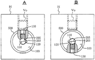
그런데, 이와 같은 배면 공급 (방식) 을, 도 11 에 나타낸 홀더 (500) 와, 그 축구멍 (110) 에 끼워 넣어져 고정되어 이루어지는 보링 바 (200) 로 이루어지는 절삭 공구 (400) 에 있어서 실현하려면, 다음과 같이 된다. 즉, 날끝 공급에 의해 관통구멍의 내경 가공을 실시하던 절삭 공구 (400) 는, 그것을 선단에서 보았을 때, 도 14-A 에 나타낸 바와 같이, 홀더 (500) 의 선단면 (103) 에 있어서 개구하는 쿨란트의 분출구 (120) 는, 보링 바 (200) 의 절삭날 (203) 측에 위치한다. 그리고, 이 절삭 공구 (400) 에 있어서, 막힘구멍의 내경 가공을 위해, 배면 공급으로 변경하는 셋업 작업에 있어서는, 도 14-A 에 있어서, 절삭 공구 (400) 가 선반의 절삭 공구대 H 에 고정되어 있다고 하면, 그 홀더 (500) 를 고정시키고 있는 절삭 공구대 H 에 있어서의 고정 볼트 Vo 와, 홀더 (500) 에 보링 바 (200) 를 고정시키고 있는 고정나사 (130) 를 각각 느슨하게, 그리고, 예를 들어 축구멍 (110) 내에 있어서 보링 바 (200) 는 회전시키지 않고, 홀더 (500) 만을 절삭 공구대 H 의 장착구멍 내에서 반전 (180 도 회전) 시켜, 고정 볼트 Vo 및 고정나사 (130) 를 비틀어 넣는다. 이로써, 도 14-B 에 나타낸 바와 같이, 홀더 (500) 의 선단면에 있어서 개구하는 쿨란트의 분출구 (120) 는, 보링 바 (200) 의 절삭날 (203) 과 반대측에 위치하게 되어, 배면 공급에 의한 가공이 가능해진다.However, in order to realize the above-described back-feed method in the
한편, 상기 종래의 절삭 공구 (400) 를 이루는 홀더 (500) 에 있어서, 보링 바 (200) 를 고정시키기 위한 고정나사 (130) 를 비틀어 넣는 나사구멍 (135) 은, 보링 바 (200) 의 섕크부를 이루는 외주면의 일측면에 형성된다 (도 11, 도 12 참조). 그리고, 이 고정나사 (130) 에 의한 보링 바 (200) 의 고정을 위한 누름은, 그 절삭날 (203) 의 레이크면 (205) 을 향하는 것과 동 방향면에 있어서 이루어진다. 이와 같은 누름 상태로 해두면, 절삭 저항의 주분력이, 고정나사 (130) 의 선단에 의한 점지지에 의한 수압 (受壓) 이 아니라, 축구멍 (110) 의 내주면으로 수압할 수 있기 때문에, 그 절삭날 (203) 의 높은 안정이 얻어지기 때문이다. 다른 한편, 상기 종래의 절삭 공구 (400) 에 있어서는, 날끝 공급이 원칙으로 되어 있기 때문에, 보링 바 (200) 의 누름면은, 그 절삭날 (203) 의 레이크면 (205) 을 향하는 것과 동 방향면으로 되고, 따라서 그 고정나사 (130) 를 비틀어 넣은 구멍은, 날끝 공급에 있어서 절삭날 (203) 의 레이크면 (205) 을 향하는 것과 동 방향면측에 형성되어 있다.The
상기한 점으로부터 분명한 바와 같이, 이 절삭 공구 (400) 에 있어서, 배면 공급으로 하기 위해, 보링 바 (200) 에 대하여 홀더 (500) 를 회전시키는 경우에는, 도 14-B 에 나타낸 바와 같이, 그 고정나사 (130) 는, 보링 바 (200) 의 절삭날 (203) 의 레이크면 (205) 과 동 방향면이 아니라, 이와 반대 방향면의 누름이 된다. 이 때문에, 이와 같은 고정에 있어서의 절삭에서는, 절삭 저항의 주분력을 고정나사 (130) 의 선단으로 수압하게 되어, 부적절한 고정 상태가 된다는 문제가 있었다.As apparent from the above point, in the
또한, 본래 이와 같은 고정나사 (130) 등의 스크루잉 작업을 포함하는 그 셋업 작업에 있어서는, 작업자가 그 고정나사 (130) 등을 육안으로 볼 수 있도록, 홀더 (500) 의 상면측으로부터 내려다 보는 것에 의한 스크루잉 작업이 되도록 절삭 공구대 H 에 고정되는 설정으로 된다. 한편, 상기한 바와 같이, 배면 공급으로 변경할 때에는, 홀더 (500) 를 절삭 공구대 H 의 장착구멍에 있어서 180 도 회전시키기 때문에, 이 고정나사 (130) 의 스크루잉 작업은, 홀더 (500) 의 하면으로부터의 스크루잉 작업이 되어 버린다. 따라서, 그 작업성이 나빠진다는 문제도 있다. 또한, 홀더 (500) 를 회전시키지 않고, 보링 바 (200) 를 180 도 회전시켜, 이 역방향으로 배치함으로써 (이른바 역바이트로 함으로써) 내경 가공을 하는 것으로 하면, 이와 같은 스크루잉 작업상의 문제는 없어진다. 그러나, 그 경우에도, 고정나사 (130) 는 레이크면 (205) 측과 반대 방향면을 누르게 되기 때문에, 부적절한 고정이 된다. 게다가, 역바이트로 하는 경우에는, 절삭날 (203) 의 날끝 위치 등의 위치에 차이가 생기기 때문에, 예를 들어 NC 선반에서는, 프로그램을 별로 작성해 둘 필요가 있는 데다, 그 설정을 변경할 필요가 있다는 문제도 있다.In the setup operation including the screwing operation of the
이러한 점으로부터, 종래는 「날끝 공급」과「배면 공급」의 어느 공급에 있어서나, 고정나사 (130) 에 의한 보링 바 (200) 의 누름이, 그 절삭날 (203) 의 레이크면 (205) 을 향하는 것과 동 방향면에서 할 수 있도록, 쿨란트의 분출구 (120) 의 위치마다 나사구멍 (135) 의 위치가 상이한 2 종류의 홀더를 갖추어 둘 필요가 있었다. 이 때문에, 홀더의 수가 몇 배로 늘어나기 때문에, 이 종류의 기계 가공의 현장에서는, 절삭 공구의 재고 및 그 관리상에 있어서 현저한 난점이 있고, 또한 가공 비용의 증대를 초래하는 원인이 되기도 하였다.In this regard, conventionally, the pressing of the
본 발명은, 상기한 내경 가공용 절삭 공구에 있어서의 문제점을 감안하여 이루어진 것으로, 보링 바의 고정에 있어서의 문제점을 발생시키지 않고, 게다가 쿨란트의 날끝 공급과 배면 공급과 같은 분출구의 위치의 차이에도 1 개의 홀더로 대응할 수 있도록 하는 것을 그 목적으로 한다.SUMMARY OF THE INVENTION The present invention has been made in view of the above-described problems in the cutting tool for an inner diameter machining, and it is an object of the present invention to provide a cutting tool for an inner diameter machining, So that one holder can cope with this.
청구항 1 에 기재된 발명은, 선단의 일측에 절삭날을 갖는 보링 바를 끼워 넣을 수 있는 축구멍과, 끼워 넣어진 보링 바를, 고정나사를 비틀어 넣음으로써 고정시키기 위한 1 또는 복수의 나사구멍이 자신의 외주면의 일측에, 상기 축구멍을 향하여 관통하여 형성되어 이루어지는 절삭 공구용 홀더로서, According to a first aspect of the present invention, there is provided a bending machine comprising: a shaft bore capable of fitting a boring bar having a cutting edge on one side of a tip end; and a boring bar sandwiched between the bending bars, A cutting tool holder formed so as to penetrate toward the shaft hole at one side of the cutting tool holder,
상기 축구멍에 끼워 넣어져 상기 고정나사의 스크루잉에 의해 고정되는 상기 보링 바의 선단을 향하여 쿨란트를 분출시킬 수 있도록 형성된 분출구가, 자신의 선단면에 있어서 개구되어 이루어지는 절삭 공구용 홀더에 있어서, And a jet port formed in the shaft so as to be capable of jetting a coolant toward the tip of the boring bar fixed by screwing of the set screw,
상기 축구멍의 직경 방향에 있어서의 상기 나사구멍과 반대측에도, 끼워 넣어진 보링 바를 고정나사를 비틀어 넣음으로써 고정시키기 위한 나사구멍이, 자신의 외주면으로부터 상기 축구멍을 향하여 관통하여 형성되어 이루어지는 것을 특징으로 한다.Characterized in that a screw hole for fixing the inserted boring bar by screwing the fixing screw is formed so as to penetrate from the outer peripheral surface of the shaft hole toward the shaft hole on the side opposite to the screw hole in the radial direction of the shaft hole .
청구항 2 에 기재된 발명은, 상기 절삭 공구용 홀더를 선단면에서 보았을 때, 상기 분출구가, 상기 나사구멍의 중심선에 수직이며, 상기 축구멍의 중심을 통과하도록 그은 직선상에 존재하도록 형성되어 있는 것을 특징으로 하는 청구항 1 에 기재된 절삭 공구용 홀더이다.The invention according to
청구항 3 에 기재된 발명은, 상기 절삭 공구용 홀더를 선단면에서 보았을 때, 상기 분출구가, 상기 나사구멍의 중심선에 수직이며, 상기 축구멍의 중심을 통과하도록 그은 직선상에 존재하지 않도록 형성되어 있는 것을 특징으로 하는 청구항 1 에 기재된 절삭 공구용 홀더이다.The invention according to
청구항 4 에 기재된 발명은, 상기 분출구는, 상기 선단면 중 상기 축구멍의 내주면에 있어서 오목하게 형성되어 개구되어 있는 것을 특징으로 하는 청구항 1 ∼ 3 중 어느 1 항에 기재된 절삭 공구용 홀더이다.According to a fourth aspect of the invention, there is provided the holder for a cutting tool according to any one of the first to third aspects, wherein the jet port is formed to be concave on the inner circumferential surface of the shaft hole in the distal end surface.
청구항 5 에 기재된 발명은, 상기 분출구는, 상기 절삭 공구용 홀더 내에, 상기 축구멍과는 연통하지 않고 형성된 유로를 통하여, 상기 선단면 중 그 축구멍의 근방에 있어서 독립된 구멍으로서 개구되어 있는 것을 특징으로 하는 청구항 1 ∼ 3 중 어느 1 항에 기재된 절삭 공구용 홀더이다.The invention according to claim 5 is characterized in that the jet port is formed as an independent hole in the vicinity of the shaft hole in the tip end face through a flow path formed in the holder for cutting tool without being in communication with the shaft hole Is a holder for a cutting tool according to any one of
청구항 6 에 기재된 발명은, 상기 나사구멍에는 그 전부에 상기 고정나사가 나사결합되어 있는 것을 특징으로 하는 청구항 1 ∼ 5 중 어느 1 항에 기재된 절삭 공구용 홀더이다.According to a sixth aspect of the present invention, there is provided a holder for a cutting tool according to any one of the first to fifth aspects, wherein the fixing screw is screwed to the screw hole.
청구항 7 에 기재된 발명은, 청구항 6 에 기재된 절삭 공구용 홀더의 상기 축구멍에 상기 보링 바가 끼워 넣어지고, 이 보링 바가, 상기 고정나사 중 그 레이크면과 동 방향면을 누르는 위치에 있는 나사구멍에 나사결합되어 있는 고정나사의 스크루잉에 의해 고정되어 이루어지는 절삭 공구이다.According to a seventh aspect of the present invention, there is provided a cutting tool holder as set forth in claim 6, wherein the boring bar is inserted into the yoke of the holder, and the boring bar is screwed into a screw hole in a position, And is fixed by the screwing of the fixed screws.
본 발명에 관련된 절삭 공구용 홀더에 의하면, 상기 구성에 의해, 그 구조의 각별한 복잡화를 초래하지 않고, 날끝 공급과 배면 공급의 어느 공급에 있어서나, 고정나사에 의한 보링 바의 고정을 위한 누름을, 그 절삭날의 레이크면이 향하는 방향과 동 방향면에서 실시할 수 있다. 이 때문에, 종래와 같이, 쿨란트의 분출구 위치가 상이한 상황에 대응할 수 있도록, 나사구멍의 위치가 상이한 2 종류의 홀더를 갖추어 둘 필요가 없어지고, 따라서 절삭 공구의 재고 및 그 관리상에 있어서의 효과에는 현저한 장점이 얻어진다. 이와 같이 본 발명에 관련된 홀더에 의하면, 상기 구성에 의해, 보링 바의 고정을 위한 고정나사의 스크루잉에 의한 누름상의 문제도 없고, 1 개의 홀더로 쿨란트의 날끝 공급과 배면 공급과 같은 분출구의 위치 변경에 대응할 수 있는 편리한 홀더로 할 수 있어, 가공 비용의 저감도 도모할 수 있는 눈에 띄게 우수한 효과가 얻어진다. 또한, 본 발명에 있어서, 분출구는, 홀더 자신의 선단면에 있어서 개구되어 이루어지는 것이지만, 날끝 공급과 배면 공급의 선택을 할 수 있으면 되고, 따라서 분출구 자체는, 그 선단면 중 축구멍의 일측에 있어서, 1 개가 개구되어 있는 것으로도 충분하지만, 복수 개구되어 있어도 된다.According to the holder for a cutting tool according to the present invention, it is possible to provide a holder for a cutting tool, which does not cause complication of its structure, , And can be performed in a direction coinciding with the direction in which the rake face of the cutting edge faces. As a result, it is not necessary to provide two types of holders having different positions of screw holes so as to be able to cope with a situation in which coolant spouting positions are different from each other as in the prior art. Therefore, Significant advantages are obtained in the effect. As described above, according to the holder according to the present invention, with the above-described configuration, there is no problem of pushing due to the screwing of the fixing screw for fixing the boring bar, It is possible to provide a convenient holder capable of coping with the change of position, and a remarkably excellent effect that can reduce the processing cost can be obtained. Further, in the present invention, the jet port is opened at the front end surface of the holder itself, but it is only necessary to be able to select the blade tip feed and the back feed, so that the jet port itself has, at its one end, , But a plurality of openings may be provided.
또한, 상기 분출구는, 청구항 2 에 기재된 바와 같이, 홀더를 선단면에서 보았을 때, 상기 나사구멍의 중심선에 수직이며, 상기 축구멍의 중심을 통과하도록 그은 직선상의 그 중심이 존재하도록 형성하는 것이 바람직하지만, 청구항 3 에 기재된 바와 같이, 상기 홀더를 선단면에서 보았을 때, 상기 분출구가, 상기 나사구멍의 중심선에 수직이며, 상기 축구멍의 중심을 통과하도록 그은 직선상에 존재하지 않도록 설치해도 된다.It is preferable that the jet port is formed such that when the holder is viewed from the front end surface, the jet port is perpendicular to the center line of the screw hole and has its center on the straight line passing through the center of the shaft hole However, as described in
본 발명에 있어서, 분출구는, 청구항 4 에 기재된 바와 같이, 그 축구멍의 내주면에 있어서 오목하게 형성한 것이어도 되고, 청구항 5 에 기재된 바와 같이, 그 축구멍과는 별개의 독립된 구멍으로서 형성해도 된다. 청구항 4 에 기재된 바와 같이 형성하는 경우에는, 그 축구멍의 내주면에 있어서 절입하도록 오목하게 형성할 수 있기 때문에, 그 형성이 용이하고, 구멍 직경이 작고, 그 내주면과 보링 바의 외주면의 간극이 작은 경우에도 유효하게 쿨란트를 공급할 수 있다. 한편, 이와 같이 형성하는 경우에는, 그 축구멍의 내주면과 보링 바의 외주면의 간극에 쿨란트가 돌아들어가거나, 고정나사의 나사결합면을 통하여 누출될 가능성이 있는 등의 밀폐상의 과제가 있다. 이에 대하여, 청구항 5 에 기재된 발명에서는 이러한 문제를 해소할 수 있다.In the present invention, the jet port may be formed concavely on the inner circumferential surface of the shaft hole as described in
또한, 본 발명의 홀더에 있어서는, 청구항 6 에 기재된 발명과 같이, 상기 나사구멍에는 그 전부에 상기 고정나사가 나사결합되어 있는 것으로 해 두는 것이 바람직하다. 이것은, 이와 같이 해 두면 고정나사가 산일되거나 잘 분실되지 않게 되고, 절삭 공구에 있어서, 날끝 공급 또는 배면 공급의 어느 공급에나 신속히 대응할 수 있기 때문이다.In the holder of the present invention, as in the invention according to claim 6, it is preferable that the fixing screw is screwed all over the screw hole. This is because the fixing screw is not scattered or lost easily if it is done in this way, and it can quickly respond to any supply of blade feed or back feed in the cutting tool.
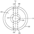
도 1 은 본 발명의 절삭 공구용 홀더를 구체화한 실시형태예의 나사구멍을 통과하는 부분 파단면도, 및 그 주요부 확대도, 그리고 각 부위의 단면도.
도 2 는 도 1 의 홀더의 선단면의 확대도.
도 3 은 도 1 의 홀더의 S4-S4 단면도.
도 4 는 도 1 의 홀더를 포함하는 절삭 공구의 분해 사시도.
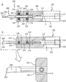
도 5A 는 도 1 의 홀더에 보링 바를 끼워 넣어 「날끝 공급」으로 고정시켜 이루어지는 절삭 공구의 단면도, 도 5B 는 그 축선을 통과하는 레이크면측에서 본 도면, 및 그 주요부 확대도.
도 6 은 도 5 의 절삭 공구를 선단에서 본 확대도.
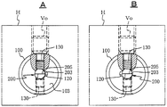
도 7A 는 도 5 의 「날끝 공급」의 절삭 공구를 절삭 공구대에 고정시켰을 때의 선단측에서 본 일부 파단면도, 도 7B 는 도 7A 에 있어서 「배면 공급」으로 했을 때의 일부 파단면도.
도 8 은 도 6 에 있어서 분출구를 변경한 다른 예를 설명하는 도면.
도 9 는 도 6 에 있어서 분출구를 변경한 다른 예를 설명하는 도면.
도 10 은 도 2, 도 8 에 있어서 분출구를 변경한 변형예를 설명하는 도면.
도 11 은 종래의 내경 가공용 절삭 공구의 일례를 나타내는 설명용 사시도, 및 그 주요부 확대도.
도 12 는 날끝 공급으로 관통구멍의 내경 가공을 하고 있는 상태의 레이크면측에서 본 설명용 평단면도.
도 13 은 배면 공급으로 막힘구멍의 내경 가공을 하고 있는 상태의 레이크면측에서 본 설명용 평단면도.
도 14A 는 도 11 의 절삭 공구를 「날끝 공급」으로 절삭 공구대에 고정시키고 있는 상태의 선단측에서 본 일부 파단면도, 도 14B 는 도 14A 에 있어서 「날끝 공급」으로부터 「배면 공급」으로 했을 때의 도면.BRIEF DESCRIPTION OF THE DRAWINGS Fig. 1 is a partial sectional view through a screw hole in an embodiment of a holder for a cutting tool according to the present invention, an enlarged view of the main part thereof, and a sectional view of each part. Fig.
Fig. 2 is an enlarged view of a front end surface of the holder of Fig. 1; Fig.
3 is a sectional view of the holder of Fig. 1 taken along line S4-S4.
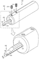
Figure 4 is an exploded perspective view of a cutting tool including the holder of Figure 1;
Fig. 5A is a cross-sectional view of a cutting tool in which a boring bar is inserted into a holder of Fig. 1 and fixed by "blade feed"; Fig. 5B is a view seen from a rake surface side passing through the axis;
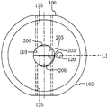
Fig. 6 is an enlarged view of the cutting tool of Fig. 5 viewed from the front end; Fig.
Fig. 7A is a partially broken-away sectional view of the cutting tool shown in Fig. 5 when the cutting tool is fixed to the cutting tool, and Fig. 7B is a partially broken-away sectional view of Fig.
Fig. 8 is a view for explaining another example in which the jet port is changed in Fig. 6; Fig.
Fig. 9 is a view for explaining another example in which the jet port is changed in Fig. 6; Fig.
Fig. 10 is a view for explaining a modified example in which the jet port is changed in Fig. 2 and Fig. 8; Fig.
11 is a perspective view for explaining a conventional example of a cutting tool for an inner diameter machining, and an enlarged view of a main part thereof.
Fig. 12 is a plan sectional view for explaining the lap surface viewed from the side in which the through hole is machined to the inner diameter by blade tip supply. Fig.
13 is a plan sectional view for explaining the lap surface viewed from the side of the inner surface of the blind hole with the back surface supply.
Fig. 14A is a partially broken-away sectional view of the cutting tool shown in Fig. 11 when it is fixed to the cutting tool by "blade feed"; Fig. 14B is a cross- Fig.
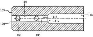
본 발명의 절삭 공구용 홀더를 구체화한 실시형태예에 대하여, 도 1 ∼ 도 4 에 기초하여 상세하게 설명한다. 도면 중 100 은 홀더로서, 환봉 (원주체) 에 있어서, 그 중심축 G 에 횡단면이 원의 내주면을 이루는 공공을 동축으로 갖고 있다. 단, 본 예에서는, 이 공공 중 홀더 (100) 의 선단면 (103) 으로부터 후단 (면) (105) 을 향하는 도중까지가, 보링 바를 끼워 넣기 위한 축구멍 (110) 으로 되어 있고, 그 도중부터 후단 (105) 까지는, 이 축구멍 (110) 보다 대직경을 이루는 쿨란트 공급용 유로 (113) 로 되어 있다. 그리고, 이 유로 (113) 의 내주면 중 홀더 (100) 의 후단면 (105) 으로 개구하는 단부에는, 그 쿨란트 공급용 배관 접속부로서 나사 (관용 테이퍼 나사) (114) 가 형성되어 있다.An embodiment of a holder for a cutting tool according to the present invention will be described in detail with reference to Figs. 1 to 4. Fig. In the figure,
한편, 홀더 (100) 의 외주면 (102) 에는, 일정한 폭을 이루는 평면 (평탄면) (106) 이 서로 평행하게, 앞뒤로 연장되는 형태로, 양측면에 있어서 동일하게 형성되어 있다. 그리고, 본 예에서는, 이 평면 (106) 중 홀더 (100) 의 선단면 (103) 측으로서 상기한 축구멍 (110) 에 대응하는 부위에, 홀더 (100) 의 직경 방향으로 축구멍 (110) 을 향하여 관통하는, 고정용 고정나사 (130) 를 비틀어 넣기 위한 나사구멍 (135) 이 형성되어 있다. 본 예에서는, 각 측면에 있어서 앞뒤로 간격을 두고 2 군데의 합계 4 군데 형성되어 있으며, 각 나사구멍 (135) 에는 고정나사 (130) (예를 들어, 육각구멍붙이 고정나사 (130)) 가 나사결합될 수 있도록 설정되어 있다. 또한, 이 평면 (106) 은, 이 홀더 (100) 를 포함하는 절삭 공구를 선반의 절삭 공구대의 장착구멍에 삽입한 후에 있어서, 고정용 볼트의 스크루잉에 의해 눌려지는 면이다. 즉, 홀더 (100) 는, 선반의 절삭 공구대에 있어서의 횡단면 원형의 장착 (공공) 내에 있어서 슬라이딩 접촉 상태로 회전할 수 있는 횡단면을 갖고, 또한 그 홀더 (100) 의 고정에 있어서 그 회전이 멈춰지도록 되어 있다.On the other hand, on the outer
한편, 축구멍 (110) 은, 도 4 의 아래 도면으로서 나타낸 보링 바 (200) 와 같이, 앞뒤의 각 단의 일측에 절삭날 (203) 을 갖고, 그 사이의 중간 부위 (섕크부위) (207) 를 끼워 넣을 수 있는 원형 구멍으로 되어 있다. 또한, 도 4 에 나타낸 보링 바 (200) 는, 앞뒤에 있어서 상호 반대를 이루는 측면에 레이크면 (205) 을 구비하고 있다. 축구멍 (110) 의 내경은, 이 중간 부위 (207) 를 그 축선 둘레로 미소한 간극으로 슬라이딩 접촉 상태로 회전시킬 수 있는 크기로 되어 있다. 본 예에서는, 홀더 (100) 를 선단면 (103) 측에서 보았을 때 (도 2 참조), 이 축구멍 (110) 의 내주면 중 고정나사 (130) 의 스크루잉용 나사구멍 (135) 의 축선 (중심선) Ls 에 수직이며, 축구멍 (110) 의 중심을 통과하도록 그은 직선 L1 상에 오목홈 (116) 이 오목하게 형성되어 있다. 그리고, 이 오목홈 (116) 은, 축구멍 (110) 의 전체 길이에 걸쳐 앞뒤로 연장되어 있다 (도 1 의 각 횡단면도, 및 도 3 참조). 또, 이 오목홈 (116) 은, 홀더 (100) 를 선단면 (103) 에서 보았을 때, 즉 축구멍 (110) 의 축선 G 에 수직인 단면으로 절단했을 때, 오목을 이루는 원호상 (초승달 형상) 을 이루고 있으며, 그 오목홈 (116) 의 홈폭 방향의 중심이 상기 직선 L1 상에 존재하도록 형성되어 있다. 또한, 이 오목홈 (116) 은, 그 홈폭 방향의 중심이 이 직선 L1 상에 존재하고 있지 않아도 된다. 이 오목홈 (116) 의 후단 (117) 은 후방의 쿨란트 공급용 유로 (113) 에 연결되고, 선단은 홀더 (100) 의 선단면 (103) 으로 개구되고, 그 분출구 (120) 를 이루는 것으로 되어 있다.On the other hand, the
이와 같은 본 예의 홀더 (100) 에 있어서는, 도 4 의 아래 도면으로서 나타낸 바와 같은, 축구멍 (110) 의 직경에 대응한, 소정의 보링 바 (200) 가 그 축구멍 (110) 에 소정량 끼워 넣어진다. 그리고, 그 중간 부위 (섕크부위) (207) 중 절삭날 (203) 의 레이크면 (205) 과 동 방향면이, 나사구멍 (135) 에 비틀어 넣어지는 고정나사 (130) 로 눌려져 고정된다. 이렇게 함으로써, 도 5, 도 6 에 나타낸 내경 가공용 절삭 공구 (300) 가 된다. 이 경우에 있어서, 「날끝 공급」의 절삭 공구로 하는 경우에는, 도 6 에 나타낸 바와 같이, 홀더 (100) 의 선단면 (103) 에서 보았을 때, 보링 바 (200) 의 선단의 일측 절삭날 (203) 이, 쿨란트의 분출구 (120) 측이 된다. 이 때문에, 이 경우에는 그 레이크면 (205) 이 향하는 면과 동 방향면측에 있는 고정나사 (130) (도 5-A, 도 6 의 위쪽 고정나사 (130)) 를 소정 토크로 비틀어 넣음으로써, 크램프하면 된다. 또한, 이 스크루잉에 앞서, 반대측 고정나사 (130) 는, 그 선단이 축구멍 (110) 의 내주면으로 돌출되지 않도록 적당히 나사결합을 해제시켜 두면 된다. 또한, 고정나사 (130) 로 고정시키는 보링 바 (200) 에 있어서의 중간 부위 (207) (섕크 부위) 에는, 레이크면 (205) 을 파악할 수 있고, 또한 회전시키지 않고 고정나사 (130) 에 의한 그 고정을 안정적으로 할 수 있도록, 레이크면 (205) 이 향하는 면과 동 방향면에, 홀더 (100) 에 있어서와 같이, 소정의 폭으로 앞뒤로 연장되는 평면 (206) 이 형성되어 있다. 덧붙여서, 도시하는 보링 바 (200) 는, 상기한 바와 같이, 앞뒤에 있어서 상호 상이한 측에 각각 절삭날 (203) 을 갖는 타입의 것이기 때문에, 그 평면 (206) 은, 홀더 (100) 에 있어서와 같이, 원형 단면을 베이스로 하여, 그 외주면의 양면에 서로 평행하게 형성되어 있다.In this
이렇게 하여, 이 절삭 공구 (300) 에 있어서는, 홀더 (100) 의 후단면 (105) 의 쿨란트 공급용 유로 (113) 의 후단 (105) 의 접속부 (관용 나사) (114) 에 쿨란트 공급 배관을 접속하여, 쿨란트 (예를 들어, 절삭액) 를 고압으로 공급하면, 그 쿨란트는, 홀더 (100) 의 선단면 (103) 에 있어서 개구하는 분출구 (120) 로부터 절삭날 (203) 을 향하여 제트류가 되어 끼얹어진다. 이로써, 이 본 예의 절삭 공구 (300) 에 있어서는, 도 7-A 에 나타낸 바와 같이, 이것을 소정의 선반의 절삭 공구대 H 의 장착구멍에 레이크면 (205) 을 위로 하여 끼워 넣고, 고정용 볼트 Vo 로 고정시킴으로써, 「날끝 공급」에 의한 원하는 내경 가공 (관통구멍의 내경 가공) 을 실시할 수 있다.In this way, in the
한편, 이와 같은 본 예의 홀더 (100) 를 사용한 절삭 공구 (300) 에 있어서, 이것을 막힘구멍의 내경 가공으로 하기 위해서 「배면 공급」으로 하는 변경을 실시하는 셋업시에 있어서는, 그 절삭 공구대 H 에 있어서 홀더 (100) 를 고정시키고 있는 고정용 볼트 Vo, 및 홀더 (100) 에 끼워 넣어져 있는 모든 고정나사 (130) 를 나사결합을 해제시켜 느슨하게 하고, 예를 들어 보링 바 (200) 를 그대로의 체세로 유지하면서, 홀더 (100) 를 보링 바 (200) 의 둘레로 반전 (180 도) 시킨다. 이렇게 함으로써, 도 7-B 에 나타낸 바와 같이, 분출구 (120) 는 「배면 공급」의 위치로 온다. 따라서, 그 위치에 있어서, 상기한 것과 동일하게 고정나사 (130) 를 비틀어 넣고, 고정용 볼트 Vo 를 비틀어 넣음으로써, 배면 공급에 의한 내경 가공을 실시할 수 있다.On the other hand, in the
즉, 상기한 바와 같이, 예를 들어 보링 바 (200) 를 회전시키지 않고, 홀더 (100) 를 보링 바 (200) 의 축선 둘레로 반전시킴으로써, 쿨란트의 분출구 (120) 는 절삭날 (203) 측과는 반대측에 위치한다. 그리고, 이 때, 보링 바 (200) 의 레이크면 (205) 측에 있어, 이 반전 전에는 그 고정의 역할을 담당하지 않은 고정나사 (130) 가, 반전 전에 있어서 레이크면 (205) 과 동 방향면에 있어서 고정되어 있던 고정나사 (130) 와 동일한 위치로 온다. 따라서, 마치 반전 전에 고정의 역할을 담당하고 있던 고정나사 (130) 를 다시 비틀어 넣도록 함으로써, 보링 바 (200) 의 재크램프가 가능하다. 이와 같이, 본 예에 관련된 홀더 (100) 에 의하면, 배면 공급의 사용 형태라도 고정나사 (130) 에 의한 보링 바 (200) 의 고정의 불안정함을 초래하지도 않고, 게다가 그 스크루잉 작업도 전과 동일한 상측으로부터 내려다보는 자세로 할 수 있기 때문에, 작업자에게 있어서도 그 작업의 간이 신속화가 도모된다. 당연한 말이지만, 이 후 다시 날끝 공급으로 되돌리는 경우에 있어서도 완전히 동일하게 할 수 있다. 또한, 날끝 공급과 배면 공급 사이의 변경 작업은, 물론 절삭 공구 (300) 를 절삭 공구대 H 로부터 분리하여 실시할 수도 있지만, 그 경우에 있어서도 동일한 효과가 얻어지는 것은 분명하다.In other words, as described above, the
또한, 상기 예에서는, 분출구 (120) 를 축구멍 (110) 의 내주면에 있어서 오목하게 만들어 형성하고, 또한 그 형상을 원호상 (초승달 형상) 인 것으로 했기 때문에, 날끝 공급과 배면 공급의 어느 공급에 있어서나, 쿨란트를 보링 바 (200) 의 선단을 향하여 그에 따르게 하도록, 게다가 가공 구멍의 내주면과의 간극이 작은 경우에도 효율적으로 공급할 수 있다. 단, 분출구 (120) 를 축구멍 (110) 의 내주면에 있어서 오목하게 만들어 형성한다 (개구한다) 고 해도, 그 유로 단면은 원호상 (초승달 형상) 에 한정되지 않고, 사각형 등 적절한 단면 형상으로 할 수도 있다. 또, 상기 예에서는, 홀더 (100) 의 후단면 (105) 으로부터, 축구멍 (110) 과 동축으로 형성한 유로 (113) 를 통하여 쿨란트를 공급하는 경우로 설명했지만, 쿨란트의 압송원 (펌프) 으로부터의 공급은, 홀더 (100) 의 외주면 (102) 중, 예를 들어 절삭 공구대에 대한 고정에 지장이 없는 선단 근처 부위에 공급 배관의 접속구 (스크루잉부) 를 형성하여, 분출구 (120) 에 연결되도록 유로 (113) 를 형성할 수도 있다.Further, in the above example, since the
또, 도 8 에 나타낸 바와 같이, 분출구 (120) 는, 홀더 (100) 의 선단면 (103) 에 있어서, 축구멍 (110) 과 조금이라도 이간된 위치에 있어서 개구시키고, 축구멍 (110) 과는 연통시키지 않고 형성된 유로 (도시 생략) 를 통하여 독립된 구멍으로서 형성해도 된다. 즉, 이 경우에는, 이 분출구 (120) 에 연결되도록 축구멍 (110) 과는 별도로 쿨란트 공급용 유로를 홀더 (100) 내에 터널상으로 형성해 두고, 쿨란트의 압송원으로부터의 공급을 위한 접속구를 홀더 (100) 의 후단면 (105) 이나 외주면에 형성하면 된다. 이와 같이 하면, 상기한 바와도 같이, 이 분출구 (120) 로부터 독립된 제트류로서 쿨란트를 분출시킬 수 있으므로, 예를 들어 고정나사 (130) 의 나사결합면 (나사구멍 (135) 의 나사와 고정나사 (130) 의 나사의 간극) 등으로부터의 쿨란트 누출 등의 문제를 회피할 수 있다. 가공하는 구멍이 소직경이더라도 비교적 큰 구멍에 있어서 유효하다.8, the
상기 예의 절삭 공구용 홀더 (100) 는, 횡단면이 원형인 환봉을 베이스로, 외주면에 서로 평행이 되는 평면 (106) 을 형성한 것으로 했지만, 절삭 공구용 홀더 (100) 자체의 외주면 형상은 적절한 것으로 할 수 있다. 그 외주면은, 예를 들어 선단면 (103) 에 이어지는 선단 근처 부위가, 그보다 후방에 이어지는 다른 부위 (절삭 공구대에 대한 장착부) 보다 소직경이어도 된다. 또, 축구멍 (110) 도 날끝 공급인지 배면 공급인지에 따라 보링 바에 따라 분출구 (120) 의 위치를 선택할 수 있으면 되고, 따라서 축구멍 (110) 의 횡단면 형상도 원에 한정되는 것은 아니다.Although the
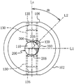
또한, 상기 예에서는, 홀더 (100) 를 선단면 (103) 측에서 보았을 때의 (도 2, 도 6 참조), 분출구 (120) 에 연결되는 오목홈 (116) 의 홈폭 방향의 중심이, 고정나사 (130) 의 스크루잉용 나사구멍 (135) 의 축선 (중심선) Ls 에 수직이며, 축구멍 (110) 의 중심을 통과하도록 그은 직선 L1 상에 존재하도록 했을 경우를 예시했지만, 이 위치는 다음과 같이 변경할 수도 있다. 즉, 상기 예에서는, 홀더 (100) 를 선단면 (103) 측에서 보았을 때 (도 2, 도 6 참조), 분출구 (120) 가 나사구멍 (135) 의 축선 (중심선) Ls 에 수직이며, 축구멍 (110) 의 중심을 통과하도록 그은 직선 L1 상에 존재하는 경우를 예시 했지만, 본 발명에 있어서는, 도 9 에 예시한 바와 같이, 분출구 (120) 는, 나사구멍 (135) 의 축선 (중심선) Ls 에 수직이며, 축구멍 (110) 의 중심을 통과하도록 그은 직선 L1 상에 존재하지 않도록 해도 된다.2 and 6), when the
도 9 에 있어서는, 분출구 (120) 및 오목홈 (116) 의 홈폭 방향의 중심이, 홀더 (100) 를 선단면 (103) 측에서 보았을 때, 나사구멍 (135) 의 축선 (중심선) Ls 에, 경사각 α (예를 들어 45 도) 가 되도록 하여 축구멍 (110) 의 중심을 통과하도록 그은 직선 L2 상에 위치하도록 하고 있다. 이 경우에는, 도 9 에 나타내는 바와 같이, 홀더 (100) 를 선단면 (103) 측에서 보았을 때, 분출구 (120) 는, 나사구멍 (135) 의 축선 (중심선) Ls 에 수직이며, 축구멍 (110) 의 중심을 통과하도록 그은 직선 L1 상에 존재하지 않는다. 동 도면은, 「날끝 공급」을 예시하는 것이지만, 이 경우에는, 예를 들어 그 분출구 (120) 와, 고정되어 있는 보링 바 (200) 의 위치 관계로부터, 「날끝 공급」인 것의, 레이크면 (205) 근처의 「날끝 공급」으로서 절삭날 (203) 에 쿨란트가 공급되는 경우를 나타내고 있다.9, the centers of the
이는 「날끝 공급」이라도, 레이크면 (205) 측으로의 쿨란트의 공급이 많이 요청되는 경우에 적절한 것이다. 또한, 이 홀더 (100) 에 있어서, 「배면 공급」으로 하는 경우에는, 배면측에서도 반대로 레이크면 (205) 과는 반대측 근처 부위에 분출구 (120) 가 위치하게 되기 때문에, 막힘구멍의 가공에 있어서, 쿨란트가 U 턴하여 되돌려질 때에는, 그 흐름에 의해 발생하는 절삭 부스러기는 레이크면 (205) 으로부터 떠오르게 하는 작용이 얻어진다. 이 때문에, 가공 조건에 따라서는 그 배출성도 높일 수 있다. 즉, 「날끝 공급」또는 「배면 공급」의 어느 공급에 있어서나, 축구멍 (110) 둘레의 어느 부위에 있어서 쿨란트를 선단측으로 분출시켜야 할지는 가공 조건에 따라 상이하기 때문에, 그에 따라 분출구 (120) 의 위치 (축구멍 (110) 둘레의 나사구멍 (135) 의 축선에 대한 분출구의 위치) 를 설정하면 되고, 따라서 상기 각도 α 는 적절히 설정하면 된다. 또한, 도 9 에서는, 상기 예 중 분출구 (120) 가 축구멍 (110) 의 내주면에 있어서 오목하게 형성되고, 그 형상이 원호상 (초승달 형상) 인 것으로 설명했지만, 이는 도 8 에 나타낸 분출구 (120) 와 같이, 홀더 (100) 의 선단면 (103) 에 있어서, 축구멍 (110) 과 이간된 위치에 있어서 독립적으로 개구시켰을 경우에도 동일하게 적용할 수 있다.This is appropriate even in the case where a supply of coolant to the
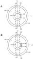
또한, 상기 예에서는, 홀더 (100) 의 선단면 (103) 에서 보았을 때, 「날끝 공급」또는 「배면 공급」의 어느 공급을 이루도록 하기 위해, 분출구 (120) 는 1 개로 이루어지는 것으로 했지만, 이는 예를 들어 도 10-A 에 나타낸 바와 같이, 분출구 (120) 가 축구멍 (110) 의 내주면에 있어서 오목하게 형성되는 경우라도, 2 이상으로 분할한 2 개의 분출구 (120) 로 해도 된다. 또, 도 10-B 에 나타낸 바와 같이, 분출구 (120) 가 독립 구멍인 경우에도 동일하다. 즉, 본 발명에 있어서, 분출구는 홀더 자신의 선단면의 축구멍의 일측에 있어서 개구되어 있으면, 그것이 복수의 분출구 또는 분출구군으로 되어 있더라도, 그 복수의 분출구에 있어서 「날끝 공급」또는 「배면 공급」의 어느 공급을 선택할 수 있으면 되기 때문이다. 그리고, 도 10-A, B 에 나타내는 어느 도면에 있어서나, 2 개로 분할된 분출구 (2 개의 분출구) (120) 는, 홀더를 선단면 (103) 에서 보았을 때, 나사구멍 (135) 의 중심선 Ls 에 수직이며, 축구멍 (110) 의 중심을 통과하도록 그은 직선 L1 이 걸쳐 있기 때문에, 이 직선 L1 상에는 존재하고 있지 않다. 한편, 도 10-A, B 에 나타내는 어느 도면에 있어서나, 2 개로 분할된 분출구 (2 개의 분출구) (120) 의 어느 것이 직선 L1 상에 존재 (겹치는) 하는 배치로 형성되어 있어도 되는 것은 분명하다. 또한, 분출구는 3 이상인 것으로 되어 있어도 된다.In the above example, the number of the
또, 본 발명에 관련된 홀더는, 보링 바의 고정에 있어서, 그 고정 부위가 레이크면측을 향하는 것과 동 방향면에 있어서, 고정나사에 의한 고정을 할 수 있고, 또한 쿨란트의 「날끝 공급」과「배면 공급」과 같은 분출구의 위치가 상이한 상황에도 1 개의 홀더로 대응할 수 있으면 되므로, 홀더 자체의 그 밖의 구조, 형상에 있어서의 제한은 없다. 또한, 보링 바의 고정에 있어서, 고정나사에 의한 고정이 「레이크면과 동 방향면」이라는 것은, 레이크면과 평행한 면 외에, 레이크면과 평행하지 않고, 경사각이 있는 면도 포함하고 있다.Further, in the holder according to the present invention, in fixing the boring bar, the fixing portion can be fixed by a fixing screw on a surface in the same direction as the rake face side, and furthermore, There is no limitation in the other structure and shape of the holder itself as long as it can cope with a situation where the position of the jet port such as " back surface supply " is different. In the fixing of the boring bar, the fixation by the fixing screw is referred to as " a surface in the same plane with the rake surface " as well as a surface parallel to the rake surface but not parallel to the rake surface.
100 절삭 공구용 홀더
102 홀더의 외주면
103 홀더의 선단면
110 홀더의 축구멍
120 홀더의 분출구
130 고정나사
135 홀더의 나사구멍
200 보링 바
203 절삭날
205 레이크면
300 절삭 공구100 Holder for cutting tools
102 outer circumference of holder
103 End face of holder
110 holder's yoke in the holder
120 Outlet of holder
130 Securing Screw
135 Screw holes in holder
200 boring bars
203 cutting edge
205 rake face
300 cutting tool
Claims (8)
끼워 넣어진 보링 바를, 고정나사를 비틀어 넣음으로써 고정시키기 위한 1 또는 복수의 나사구멍이 자신의 외주면의 일측에, 상기 축구멍을 향하여 관통하여 형성되어 이루어지는 절삭 공구용 홀더로서,
상기 축구멍에 끼워 넣어져 상기 고정나사의 스크루잉에 의해 고정되는 상기 보링 바의 선단을 향하여 쿨란트를 분출시킬 수 있도록 형성된 분출구가, 자신의 선단면에 있어서 개구되어 이루어지는 절삭 공구용 홀더에 있어서,
상기 축구멍의 직경 방향에 있어서의 상기 나사구멍과 반대측에도, 끼워 넣어진 보링 바를 고정나사를 비틀어 넣음으로써 고정시키기 위한 나사구멍이, 자신의 외주면으로부터 상기 축구멍을 향하여 관통하여 형성되어 이루어지는 것을 특징으로 하는 절삭 공구용 홀더.A shaft bush capable of fitting a boring bar having a cutting edge on one side of the tip,
A holder for a cutting tool in which one or a plurality of screw holes for fixing an inserted boring bar by screwing a set screw is formed on one side of an outer peripheral surface of the one or more screw holes,
And a jet port formed in the yoke so as to be capable of jetting a coolant toward the tip of the boring bar fixed by screwing of the set screw is opened in its own end surface,
Characterized in that a screw hole for fixing the inserted boring bar by screwing the fixing screw is formed so as to penetrate from the outer peripheral surface of the shaft hole toward the shaft hole on the side opposite to the screw hole in the radial direction of the shaft hole And a holder for a cutting tool.
상기 절삭 공구용 홀더를 선단면에서 보았을 때, 상기 분출구가, 상기 나사구멍의 중심선에 수직이며, 상기 축구멍의 중심을 통과하도록 그은 직선상에 존재하도록 형성되어 있는 것을 특징으로 하는 절삭 공구용 홀더.The method according to claim 1,
Characterized in that when the holder for the cutting tool is viewed from the front end surface, the jet port is formed so as to be perpendicular to the center line of the screw hole and to be on a straight line passing through the center of the shaft hole .
상기 절삭 공구용 홀더를 선단면에서 보았을 때, 상기 분출구가, 상기 나사구멍의 중심선에 수직이며, 상기 축구멍의 중심을 통과하도록 그은 직선상에 존재하지 않도록 형성되어 있는 것을 특징으로 하는 절삭 공구용 홀더.The method according to claim 1,
Characterized in that when the holder for the cutting tool is viewed from the front end surface, the jet port is formed so as to be perpendicular to the center line of the screw hole and not to exist on a straight line passing through the center of the shaft hole holder.
상기 분출구는, 상기 선단면 중 상기 축구멍의 내주면에 있어서 오목하게 형성되어 개구되어 있는 것을 특징으로 하는 절삭 공구용 홀더.4. The method according to any one of claims 1 to 3,
And the jet port is formed to be concave on the inner circumferential surface of the shaft hole in the distal end surface.
상기 분출구는, 상기 절삭 공구용 홀더 내에, 상기 축구멍과는 연통하지 않고 형성된 유로를 통하여, 상기 선단면 중 그 축구멍의 근방에 있어서 독립된 구멍으로서 개구되어 있는 것을 특징으로 하는 절삭 공구용 홀더.4. The method according to any one of claims 1 to 3,
Wherein the jetting port is formed as an independent hole in the vicinity of the shaft hole of the tip end face through a flow path formed in the holder for cutting tool without being in communication with the shaft bore.
상기 나사구멍에는 그 전부에 상기 고정나사가 나사결합되어 있는 것을 특징으로 하는 절삭 공구용 홀더.The method according to any one of claims 1 to 5 or 8,
And the fixing screw is threadedly engaged with the screw hole.
상기 분출구는, 상기 선단면 중 상기 축구멍의 내주면에 있어서 오목하게 형성되어 개구되어 있는 오목홈이며,
상기 오목홈은, 상기 절삭 공구용 홀더를 선단면에서 보았을 때, 원호상, 또는 초승달 형상을 이루고 있는 것을 특징으로 하는 절삭 공구용 홀더.4. The method according to any one of claims 1 to 3,
Wherein the jet port is a concave groove which is opened and formed concavely in the inner peripheral surface of the shaft hole in the end surface,
Wherein the concave groove has an arc shape or a crescent shape when the holder for a cutting tool is viewed from a front end surface thereof.
Applications Claiming Priority (3)
| Application Number | Priority Date | Filing Date | Title |
|---|---|---|---|
| JPJP-P-2013-217676 | 2013-10-18 | ||
| JP2013217676A JP2015077669A (en) | 2013-10-18 | 2013-10-18 | Cutting tool holder and cutting tool |
| PCT/JP2014/004852 WO2015056406A1 (en) | 2013-10-18 | 2014-09-22 | Cutting tool holder and cutting tool |
Publications (1)
| Publication Number | Publication Date |
|---|---|
| KR20160054600A true KR20160054600A (en) | 2016-05-16 |
Family
ID=52827867
Family Applications (1)
| Application Number | Title | Priority Date | Filing Date |
|---|---|---|---|
| KR1020167009766A KR20160054600A (en) | 2013-10-18 | 2014-09-22 | Cutting tool holder and cutting tool |
Country Status (6)
| Country | Link |
|---|---|
| US (1) | US20160236282A1 (en) |
| EP (1) | EP3059035A4 (en) |
| JP (1) | JP2015077669A (en) |
| KR (1) | KR20160054600A (en) |
| CN (1) | CN105636726A (en) |
| WO (1) | WO2015056406A1 (en) |
Families Citing this family (10)
| Publication number | Priority date | Publication date | Assignee | Title |
|---|---|---|---|---|
| CH707123A2 (en) * | 2012-10-25 | 2014-04-30 | Utilis Ag | Clamping device with a coolant channel for cooling of machining tools in lathes. |
| JP6035696B1 (en) * | 2015-12-07 | 2016-11-30 | 株式会社タンガロイ | Cutting tool and support member |
| DE102016105354B4 (en) * | 2016-03-22 | 2018-03-22 | Hartmetall-Werkzeugfabrik Paul Horn Gmbh | Machining tool |
| DE102017214155A1 (en) * | 2017-08-14 | 2019-02-14 | MAPAL Fabrik für Präzisionswerkzeuge Dr. Kress KG | chuck |
| CN109129736A (en) * | 2018-07-23 | 2019-01-04 | 威尔廉(苏州)机械有限公司 | A kind of machining cutter and its mounting and clamping system |
| CN109676512A (en) * | 2018-11-13 | 2019-04-26 | 江苏科比特科技有限公司 | A kind of cutting tool dulling machine quick-clamping knife bar |
| DE102019001347A1 (en) * | 2019-02-26 | 2020-08-27 | Hubert Kimmich | Device for fastening a boring bar |
| US11819928B2 (en) | 2020-10-14 | 2023-11-21 | Iscar, Ltd. | Insert holder having insert receiving recess with insert orientation projection and cutting tool |
| CN113843901B (en) * | 2021-09-15 | 2023-12-29 | 浙江富乐德石英科技有限公司 | Processing method of quartz ring products |
| CN117245114A (en) * | 2023-06-30 | 2023-12-19 | 北京新风航天装备有限公司 | Device and method for machining precise coaxial holes in narrow space |
Family Cites Families (8)
| Publication number | Priority date | Publication date | Assignee | Title |
|---|---|---|---|---|
| JPS54138183U (en) * | 1978-03-20 | 1979-09-25 | ||
| JPH0585535U (en) * | 1992-04-20 | 1993-11-19 | 株式会社日研工作所 | Tool holder |
| JPH0657502U (en) * | 1992-07-29 | 1994-08-09 | 京セラ株式会社 | Cutting tools |
| US7357607B2 (en) * | 2003-08-07 | 2008-04-15 | Pv Engineering & Mfg., Inc. | Tool holder |
| FR2866822B1 (en) * | 2004-03-01 | 2007-04-06 | Rusch Outil De Prec | TURNING TOOL |
| SE530182C2 (en) * | 2006-01-10 | 2008-03-18 | Sandvik Intellectual Property | Turning boom for internal turning with fluid duct |
| CN201168796Y (en) * | 2008-02-04 | 2008-12-24 | 映钒企业有限公司 | Combined type lathe cutter structure |
| JP2010240817A (en) * | 2009-04-01 | 2010-10-28 | Yukiji Boku | Holder and sleeve for boring cutting tool |
-
2013
- 2013-10-18 JP JP2013217676A patent/JP2015077669A/en active Pending
-
2014
- 2014-09-22 WO PCT/JP2014/004852 patent/WO2015056406A1/en active Application Filing
- 2014-09-22 KR KR1020167009766A patent/KR20160054600A/en not_active Application Discontinuation
- 2014-09-22 EP EP14853437.3A patent/EP3059035A4/en not_active Withdrawn
- 2014-09-22 CN CN201480057384.9A patent/CN105636726A/en active Pending
- 2014-09-22 US US15/027,745 patent/US20160236282A1/en not_active Abandoned
Also Published As
| Publication number | Publication date |
|---|---|
| CN105636726A (en) | 2016-06-01 |
| JP2015077669A (en) | 2015-04-23 |
| US20160236282A1 (en) | 2016-08-18 |
| EP3059035A1 (en) | 2016-08-24 |
| EP3059035A4 (en) | 2017-05-24 |
| WO2015056406A1 (en) | 2015-04-23 |
Similar Documents
| Publication | Publication Date | Title |
|---|---|---|
| KR20160054600A (en) | Cutting tool holder and cutting tool | |
| JP5714032B2 (en) | Rotary cutting tool with adjustable cooling mechanism | |
| US8764354B2 (en) | Cutting tool for a machine tool | |
| KR102334778B1 (en) | Turning tool holder and cutting tool insert | |
| KR101958072B1 (en) | Tool holder and cutting tool | |
| JP6283157B2 (en) | Cutting tools | |
| KR101779621B1 (en) | Milling tool | |
| US6626614B2 (en) | Throw-away cutting tool | |
| JP4802095B2 (en) | Drill | |
| US8123442B2 (en) | Expandable multi-flute reamer with tapered pin | |
| JP5310191B2 (en) | Insert detachable cutting tool | |
| US20090214305A1 (en) | Coolant nozzles for milling cutters | |
| JP2009220200A (en) | Fluid feeding unit | |
| JP2010094748A (en) | Cutting tool | |
| CN110614400A (en) | Miniature cutter with coolant liquid delivery hole | |
| JP2013111709A (en) | Tool for processing inner-diameter groove | |
| WO2017126145A1 (en) | Hob | |
| JP5952126B2 (en) | Inserts and cutting tools | |
| JP2009291858A (en) | Boring tool | |
| CN211804249U (en) | Screw tap and processing device | |
| CN220782269U (en) | Split clamping boring cutter | |
| CN210615262U (en) | Miniature cutter with coolant liquid delivery hole | |
| KR101946199B1 (en) | A Machine Tools Having a Structure of Providing a Cutting Fluid through a Inner Path | |
| JP2004160625A (en) | Deep hole cutting tool | |
| KR20110087832A (en) | Cutting tool having side groove for coolant and holder for cutting tool |
Legal Events
| Date | Code | Title | Description |
|---|---|---|---|
| A201 | Request for examination | ||
| E902 | Notification of reason for refusal | ||
| E601 | Decision to refuse application |