WO2017098914A1 - Cutting tool - Google Patents
Cutting tool Download PDFInfo
- Publication number
- WO2017098914A1 WO2017098914A1 PCT/JP2016/084532 JP2016084532W WO2017098914A1 WO 2017098914 A1 WO2017098914 A1 WO 2017098914A1 JP 2016084532 W JP2016084532 W JP 2016084532W WO 2017098914 A1 WO2017098914 A1 WO 2017098914A1
- Authority
- WO
- WIPO (PCT)
- Prior art keywords
- plate
- cutting tool
- support member
- cutting
- fluid
- Prior art date
Links
Images
Classifications
-
- B—PERFORMING OPERATIONS; TRANSPORTING
- B23—MACHINE TOOLS; METAL-WORKING NOT OTHERWISE PROVIDED FOR
- B23B—TURNING; BORING
- B23B27/00—Tools for turning or boring machines; Tools of a similar kind in general; Accessories therefor
- B23B27/10—Cutting tools with special provision for cooling
-
- B—PERFORMING OPERATIONS; TRANSPORTING
- B23—MACHINE TOOLS; METAL-WORKING NOT OTHERWISE PROVIDED FOR
- B23B—TURNING; BORING
- B23B27/00—Tools for turning or boring machines; Tools of a similar kind in general; Accessories therefor
- B23B27/04—Cutting-off tools
-
- B—PERFORMING OPERATIONS; TRANSPORTING
- B23—MACHINE TOOLS; METAL-WORKING NOT OTHERWISE PROVIDED FOR
- B23B—TURNING; BORING
- B23B27/00—Tools for turning or boring machines; Tools of a similar kind in general; Accessories therefor
- B23B27/08—Cutting tools with blade- or disc-like main parts
-
- B—PERFORMING OPERATIONS; TRANSPORTING
- B23—MACHINE TOOLS; METAL-WORKING NOT OTHERWISE PROVIDED FOR
- B23B—TURNING; BORING
- B23B29/00—Holders for non-rotary cutting tools; Boring bars or boring heads; Accessories for tool holders
- B23B29/04—Tool holders for a single cutting tool
- B23B29/043—Tool holders for a single cutting tool with cutting-off, grooving or profile cutting tools, i.e. blade- or disc-like main cutting parts
-
- B—PERFORMING OPERATIONS; TRANSPORTING
- B23—MACHINE TOOLS; METAL-WORKING NOT OTHERWISE PROVIDED FOR
- B23B—TURNING; BORING
- B23B2220/00—Details of turning, boring or drilling processes
- B23B2220/12—Grooving
- B23B2220/126—Producing ring grooves
Definitions
- the present invention relates to a cutting tool for forming a groove in a workpiece.
- Patent Document 1 discloses a cutting tool for forming a groove on an end surface of a workpiece.
- the cutting tool includes a plate member.
- the plate-like member is used to adjust the protruding amount of the blade part to an appropriate one according to the depth of the groove to be processed.
- the plate-like member is curved when viewed from the front end side, and is fixed to the tool block by a clamp member.
- it is common to inject a coolant for cooling the blade portion from a hose or the like and supply the coolant to the blade portion.
- an object of the present invention is to provide a cutting tool capable of reliably supplying a fluid to a blade portion disposed inside a groove.
- a cutting tool has a plate-like member provided with a blade part at the tip, a support member that supports the plate-like member so as to project the blade part, and a fluid that cools the blade part. And a fluid supply part for ejecting the fluid from the ejection port.
- the support member has a non-contact surface that forms a gap with the plate-like member. The gap is opened toward the side where the blade is provided.
- the ejection port is disposed in the gap and ejects fluid toward the plate member.
- the fluid supply unit has a flow path through which the fluid passes inside the support member, and the injection port is opened on the non-contact surface.
- the non-contact surface is formed by cutting out the end of the support member.
- the plate-like member is curved so as to protrude toward the support member.
- the plate member is slidable with respect to the support member, and the cutting tool is provided with a fixing means for fixing the plate member.
- the fixing member preferably includes a pressing member that presses the plate-shaped member toward the support member, and a fastening member that fastens the pressing member to the support member.
- the plate-like member has a plate-shaped main body and a cutting insert having a blade portion, and the cutting insert is detachably attached to the main body.
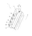
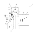
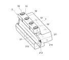
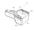
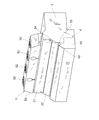
- FIG. 1 It is a perspective view of the cutting tool concerning one embodiment. It is a front view of the cutting tool of FIG. It is a perspective view of the cutting tool of FIG. It is a perspective view of the cutting tool of FIG. It is a perspective view of the cutting insert of FIG. It is a perspective view of the supporting member and fixing member of FIG. It is explanatory drawing of cutting with the cutting tool of FIG.
- the cutting tool 1 of this embodiment includes a plate-like member 2, a support member 3, and a fixing member 5. Furthermore, as shown in FIG. 2, the cutting tool 1 includes a coolant supply unit 4.
- the plate-like member 10 has a main body 21 and a cutting insert 22.
- the main body 21 has a curved plate shape.
- the main body 21 has an outer peripheral surface 21a, an inner peripheral surface 21b, and end surfaces 21c and 21d as outer surfaces.
- the outer peripheral surface 21a and the inner peripheral surface 21b are curved in a substantially arc shape when viewed from the front.
- the end surfaces 21c and 21d are planes that connect the end portion of the outer peripheral surface 21a and the end portion of the inner peripheral surface 21b.
- a tip seat 211 is formed at the end of the main body 21 in the distal direction.
- the tip seat 211 is a notch formed in a corner portion of the main body 21.
- the chip seat 11 has a bottom surface 212 and a wall portion 213 disposed on the rear end side.
- a mounting hole 214 is formed in the wall portion 213 of the chip seat 211.
- the cutting insert 22 has a tip 221 and a protrusion 222.
- the distal end portion 221 has blade portions 221a and 221b at the ridge line portion.
- the blade portion 221a is a cutting blade that cuts the workpiece and forms the bottom of the groove.
- the blade portion 221b is a cutting blade that cuts the workpiece and forms the side portion of the groove.
- the protrusion 222 protrudes from one side surface of the tip 221.
- the cutting insert 22 is fixed to the chip seat 211 of the main body 21. Specifically, the cutting insert 22 is fixed to the chip seat 11 by the protrusion 222 being inserted into the mounting hole 214 and being sandwiched by the main body 21. A part of the outer surface of the tip portion 221 of the cutting insert 22 is supported in contact with the bottom surface 212 of the chip seat 211. As shown in FIG. 1, the cutting insert 22 is fixed to the chip seat 211 in a state where the blade portions 221a and 221b are exposed.
- the support member 3 is a member that supports the plate-like member 2 so that the cutting insert 22 protrudes in the distal direction from the end of the support member 3.
- a plurality of screw holes (not shown) that are screwed with screws 52 of the fixing member 5 described later are formed.
- the support member 3 has a first wall surface 31, a second wall surface 32, and a third wall surface 33.
- the first wall surface 31, the second wall surface 32, and the third wall surface 33 are all flat surfaces and come into contact with the main body 21 of the plate-like member 2.
- the first wall surface 31 contacts a part of the outer peripheral surface 21 a of the main body 21.
- the second wall surface 32 is disposed so as to form an obtuse angle with respect to the first wall surface 31, and contacts the other part of the outer peripheral surface 21 a of the main body 21.
- the third wall surface 33 is in contact with the end surface 21c of the main body 21 and supports the plate member 2 so that it does not fall.
- the support member 3 is supported by the first wall surface 31, the second wall surface 32, and the third wall surface 33, so that the support member 3 can slide in the distal direction with respect to the support member 3 unless fixed by the fixing member 5 described later. ing.
- a notch 34 is disposed at the tip of the first wall 31.
- the notch 34 is shaped like a cylinder cut obliquely. As shown in FIG. 2, the notch 34 is a surface that is not in contact with the outer peripheral surface 21 a of the plate-like member 2 supported by the support member 3. That is, the notch 34 forms a gap 34 a between the notch 34 and the outer peripheral surface 21 a of the plate-like member 2 supported by the support member 3. The notch 34 reaches the end surface 3a in the front end direction of the support member 3, and a part of the end surface 3a is also notched.
- the coolant supply unit 4 supplies coolant to the blade portions 221a and 221b of the cutting insert 22 and cools the blade portions 221a and 221b.
- the coolant supply unit 4 includes a flow path 41 and an injection port 42.
- the channel 41 is a hole formed so as to extend from the outer surface of the support member 3 toward the inside.
- An injection port 42 serving as an outlet of the flow path 41 is opened in the notch 34.
- the injection port 42 faces the tip direction. That is, the injection port 42 is opened so as to inject the coolant flowing through the flow path 41 toward the distal end.
- the injection port 42 is opened toward the plate-like member 2.
- the injection port 42 is opened so that the normal line thereof faces the plate-like member 2.
- the coolant flowing in the flow path 41 may be either a liquid or a gas as long as it is a fluid used for cooling the blade portions 221a and 221b.
- the gas includes a mist.
- the fixing member 5 is a member that fixes the slidable plate-like member 2 to the support member 3 as described above. As shown in FIG. 1, the fixing member 5 includes a pressing member 51 and a plurality of screws 52.
- the pressing member 51 has a contact surface 51a which is a flat surface. Further, the pressing member 51 has a plurality of through holes (not shown) penetrating from the upper surface to the lower surface.
- the pressing member 51 is disposed above the support member 3 so that the contact surface 51 a is in surface contact with the end surface 21 d of the plate-like member 2.
- the screw 52 is inserted into the through hole of the pressing member 51 and is screwed into a screw hole formed on the upper surface of the support member 3. As a result, the pressing member 51 is fastened to the support member 3.
- the head of the screw 52 presses the pressing member 51 downward.
- the pressing member 51 presses the end surface 21d of the plate-like member 2 downward on the contact surface 51a. Accordingly, the plate-like member 2 is sandwiched between the contact surface 51 a and the third wall surface 33, and the outer peripheral surface 21 a is supported by the first wall surface 31 and the second wall surface 32, and is fixed to the support member 3. Is done.
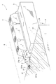
- FIG. 6 shows a cross section of the workpiece 9 cut by the cutting tool 1.
- FIG. 6 shows a cross-section of the workpiece 9 in a transparent manner.
- the workpiece 9 cut by the cutting tool 1 rotates in the direction indicated by the arrow R around the shaft 8 that is separated from the plate member 2.
- the blade portion 221 a of the cutting insert 22 cuts the end surface 91.
- the cutting insert 22 enters the inside of the workpiece 9. Thereby, an annular groove 92 is formed in the end surface 91 of the workpiece 9.
- the gap 34a (see FIG. 2) formed in the notch 34 of the support member 3 is opened toward the workpiece 9 side. Therefore, the injection port 42 arranged in the gap 34 a injects the coolant C toward the workpiece 9 as indicated by the arrow E.
- a part of the coolant C injected from the injection port 42 also goes to the plate-like member 2.
- the coolant C adheres to the outer peripheral surface 21 a of the plate-like member 2, it moves along the outer peripheral surface 21 a and flows into the groove 92.
- the coolant C reaches the blade portions 221 a and 221 b of the cutting insert 22 disposed inside the groove 92. Therefore, even when the processing progresses and the entire blade portions 221a and 221b of the cutting insert 22 are disposed inside the groove 92, the blade portions 221a and 221b can be reliably cooled.
- the cutting tool 1 does not inject all the coolant C directly from the injection port 42 toward the blade portions 221a and 221b, but dares to inject the coolant C toward the plate member 2 as well. Accordingly, the coolant C can be reliably supplied to the blade portions 221a and 221b disposed inside the narrow groove 92 without being blocked by the workpiece 9.
- the plate-like member 2 and the cutting insert 22 fixed to the plate-like member 2 are cooled.
- the blade portions 221a and 221b can be indirectly cooled.
- the blade portions 221a and 221b are cooled to reduce wear and extend their life.
- the coolant supply unit 4 has a flow path 41 through which the coolant C is passed inside the support member 3.
- the injection port 42 is opened on the non-contact surface 34. According to this configuration, the injection port 42 can be disposed in the vicinity of the plate-like member 2 without using a hose or the like. As a result, the coolant C injected from the injection port 42 can be reliably moved along the plate-like member 2 and can be reliably supplied to the blade portions 221a and 221b.
- the notch 34 which is a non-contact surface is formed by notching the end portion of the support member 3. According to this configuration, it is possible to suppress the chips generated when the workpiece 9 is cut from adhering to the injection port 42. As a result, the coolant C injected from the injection port 42 can be reliably moved along the plate-like member 2 and can be reliably supplied to the blade portions 221a and 221b.
- the present invention is not limited to the above-mentioned embodiment. That is, the present invention can be variously modified without departing from the essential technical idea of “supplying fluid to the blade portion using a plate-like member”.
- a non-contact surface disposed at a predetermined interval from the plate-like member 2 may be provided on a part of the outer surface of the support member 3 so as to extend along the plate-like member 2.
- a gap in which the blade portions 221a and 221b are opened may be formed between the non-contact surface and the plate-like member 2, and coolant may be injected into the gap.
- the injection port is provided on the non-contact surface of the support member 3. Thereby, all the coolant injected from the injection port moves along the plate-like member 2.
- the amount of coolant reaching the blade portions 221a and 221b disposed inside the groove 92 can be increased as compared with the above embodiment.
- the plate-like member may be flat without being curved as in the above embodiment.
- the blade portion provided on the plate-like member is not detachable as in the above embodiment, but may be integrated with the plate-like member by brazing or the like.
Abstract
A cutting tool 1 comprises a plate member 2 that is provided with cutting portions 221a, 221b on the distal end, a support member 3 that supports the plate member 2 so that the cutting portions 221a, 221b protrude, and a coolant supply unit 4 that has a spray port 42 and that sprays a fluid to cool the cutting portions 221a, 221b from the spray port 42. The support member 3 comprises a non-contact face 34 that forms a gap 34a with the exterior face of the plate member 2. The gap 34a opens toward the side on which the cutting portions 221a, 221b are provided. The spray port 42 is disposed in the gap 34a and sprays a fluid toward the plate member 2.
Description
本発明は、被加工物に溝を形成する切削工具に関する。
The present invention relates to a cutting tool for forming a groove in a workpiece.
従来の切削工具として、特許文献1に示すものが知られている。特許文献1には、被加工物の端面に溝を形成するための切削工具が示されている。当該切削工具は、板状部材を備えている。板状部材は、加工する溝の深さに応じて、刃部の突出量を適切なものに調節するために用いられる。板状部材は先端側からみて湾曲しており、クランプ部材によってツールブロックに固定される。このような切削工具を用いる場合は、刃部を冷却するためのクーラントをホースなどから噴射し、刃部に供給することが一般的である。
As a conventional cutting tool, the one shown in Patent Document 1 is known. Patent Document 1 discloses a cutting tool for forming a groove on an end surface of a workpiece. The cutting tool includes a plate member. The plate-like member is used to adjust the protruding amount of the blade part to an appropriate one according to the depth of the groove to be processed. The plate-like member is curved when viewed from the front end side, and is fixed to the tool block by a clamp member. When such a cutting tool is used, it is common to inject a coolant for cooling the blade portion from a hose or the like and supply the coolant to the blade portion.
特許文献1が開示する切削工具の場合、加工が進行して刃部全体が被加工物の溝の内側に配置されてしまうと、溝の外側に配置されたホースから供給されるクーラントは溝の内側に進入できず、刃部に到達できなくなるおそれがあった。その結果、刃部は冷却されることなく高温となり、短時間で摩耗するという課題があった。
In the case of the cutting tool disclosed in Patent Document 1, when the processing proceeds and the entire blade portion is disposed inside the groove of the workpiece, the coolant supplied from the hose disposed outside the groove is the groove. There was a possibility that the blade could not reach the inside and could not reach the blade. As a result, there is a problem that the blade portion becomes high temperature without being cooled and wears in a short time.
本発明は上記の課題を解決するためのものである。すなわち、本発明は、溝の内側に配置された刃部に確実に流体を供給可能な切削工具を提供することを目的とする。
The present invention is for solving the above problems. That is, an object of the present invention is to provide a cutting tool capable of reliably supplying a fluid to a blade portion disposed inside a groove.
本発明に係る切削工具は、先端に刃部が設けられた板状部材と、刃部を突出させるように板状部材を支持する支持部材と、噴射口を有し、刃部を冷却する流体を噴射口から噴射する流体供給部と、を備える。支持部材は、板状部材との間に隙間を形成する非接触面を有する。隙間は、刃部が設けられた側に向かって開放される。噴射口は、隙間に配置されるとともに、板状部材に向けて流体を噴射する。
A cutting tool according to the present invention has a plate-like member provided with a blade part at the tip, a support member that supports the plate-like member so as to project the blade part, and a fluid that cools the blade part. And a fluid supply part for ejecting the fluid from the ejection port. The support member has a non-contact surface that forms a gap with the plate-like member. The gap is opened toward the side where the blade is provided. The ejection port is disposed in the gap and ejects fluid toward the plate member.
流体供給部は、流体を通過させる流路を支持部材の内部に有し、噴射口は、非接触面に開設されていることも好ましい。
It is also preferable that the fluid supply unit has a flow path through which the fluid passes inside the support member, and the injection port is opened on the non-contact surface.
非接触面は、支持部材の端部を切り欠くことによって形成されていることも好ましい。
It is also preferable that the non-contact surface is formed by cutting out the end of the support member.
板状部材は、支持部材に向かって突出するように湾曲していることも好ましい。
It is also preferable that the plate-like member is curved so as to protrude toward the support member.
板状部材は、支持部材に対して摺動可能とされ、切削工具は、板状部材を固定するための固定手段を備えることも好ましい。
It is also preferable that the plate member is slidable with respect to the support member, and the cutting tool is provided with a fixing means for fixing the plate member.
固定部材は、板状部材を支持部材に向って押圧する押圧部材と、押圧部材を支持部材に締結する締結部材と、を有することも好ましい。
The fixing member preferably includes a pressing member that presses the plate-shaped member toward the support member, and a fastening member that fastens the pressing member to the support member.
板状部材は、板形状を呈する本体と、刃部を有する切削インサートと、を有し、切削インサートは、本体に着脱自在に装着されることも好ましい。
It is also preferable that the plate-like member has a plate-shaped main body and a cutting insert having a blade portion, and the cutting insert is detachably attached to the main body.
本発明によれば、溝の内側に配置された刃部に確実に流体を供給可能な切削工具を提供することができる。
According to the present invention, it is possible to provide a cutting tool capable of reliably supplying a fluid to the blade portion disposed inside the groove.
以下、一実施形態を、図面を参照しながら説明する。なお、図1の矢印A方向を先端方向として説明する。
Hereinafter, an embodiment will be described with reference to the drawings. Note that the direction of arrow A in FIG.
図1に示すように、本実施形態の切削工具1は、板状部材2と、支持部材3と、固定部材5と、を備えている。さらに、図2に示すように、切削工具1は、クーラント供給部4を備えている。
As shown in FIG. 1, the cutting tool 1 of this embodiment includes a plate-like member 2, a support member 3, and a fixing member 5. Furthermore, as shown in FIG. 2, the cutting tool 1 includes a coolant supply unit 4.
図1及び図2に示すように、板状部材10は、本体21と、切削インサート22と、を有している。本体21は湾曲した板形状を呈している。図2に示すように、本体21は、外側面として外周面21a、内周面21b及び端面21c,21dを有している。外周面21a及び内周面21bは、正面視で略円弧状に湾曲している。端面21c,21dは、外周面21aの端部と内周面21bの端部とを接続する平面である。
As shown in FIGS. 1 and 2, the plate-like member 10 has a main body 21 and a cutting insert 22. The main body 21 has a curved plate shape. As shown in FIG. 2, the main body 21 has an outer peripheral surface 21a, an inner peripheral surface 21b, and end surfaces 21c and 21d as outer surfaces. The outer peripheral surface 21a and the inner peripheral surface 21b are curved in a substantially arc shape when viewed from the front. The end surfaces 21c and 21d are planes that connect the end portion of the outer peripheral surface 21a and the end portion of the inner peripheral surface 21b.
図3に示すように、先端方向における本体21の端部には、チップ座211が形成されている。チップ座211は、本体21の角部に形成された切り欠きである。チップ座11は、底面212と、後端側に配置される壁部213とを有している。チップ座211の壁部213には、取り付け穴214が形成されている。
As shown in FIG. 3, a tip seat 211 is formed at the end of the main body 21 in the distal direction. The tip seat 211 is a notch formed in a corner portion of the main body 21. The chip seat 11 has a bottom surface 212 and a wall portion 213 disposed on the rear end side. A mounting hole 214 is formed in the wall portion 213 of the chip seat 211.
図4に示されるように、切削インサート22は、先端部221と、突起部222と、を有している。先端部221は、その稜線部に刃部221a,221bを有している。刃部221aは、被加工物を切削して溝の底部を形成する切れ刃である。刃部221bは、被加工物を切削して溝の側部を形成する切れ刃である。突起部222は、先端部221の一側面から突出している。
As shown in FIG. 4, the cutting insert 22 has a tip 221 and a protrusion 222. The distal end portion 221 has blade portions 221a and 221b at the ridge line portion. The blade portion 221a is a cutting blade that cuts the workpiece and forms the bottom of the groove. The blade portion 221b is a cutting blade that cuts the workpiece and forms the side portion of the groove. The protrusion 222 protrudes from one side surface of the tip 221.
切削インサート22は、本体21のチップ座211に固定されている。詳細には、切削インサート22は、その突起部222が取り付け穴214に嵌入し、本体21によって挟持されることにより、チップ座11に固定される。切削インサート22が有する先端部221の外側面の一部は、チップ座211の底面212と当接して支持される。図1に示されるように、切削インサート22は、刃部221a,221bが露出した状態でチップ座211に固定される。
The cutting insert 22 is fixed to the chip seat 211 of the main body 21. Specifically, the cutting insert 22 is fixed to the chip seat 11 by the protrusion 222 being inserted into the mounting hole 214 and being sandwiched by the main body 21. A part of the outer surface of the tip portion 221 of the cutting insert 22 is supported in contact with the bottom surface 212 of the chip seat 211. As shown in FIG. 1, the cutting insert 22 is fixed to the chip seat 211 in a state where the blade portions 221a and 221b are exposed.
図1に示すように、支持部材3は、切削インサート22を、支持部材3の端部よりも先端方向に突出させるように板状部材2を支持する部材である。支持部材3の上面には、後述する固定部材5のねじ52と螺合する不図示の複数のねじ穴が形成されている。
As shown in FIG. 1, the support member 3 is a member that supports the plate-like member 2 so that the cutting insert 22 protrudes in the distal direction from the end of the support member 3. On the upper surface of the support member 3, a plurality of screw holes (not shown) that are screwed with screws 52 of the fixing member 5 described later are formed.
さらに、図2及び図5に示すように、支持部材3は、第1壁面31、第2壁面32及び第3壁面33を有している。第1壁面31、第2壁面32及び第3壁面33はいずれも平面であり、板状部材2の本体21と当接する。詳細には、図2に示すように、第1壁面31は、本体21の外周面21aの一部と当接する。第2壁面32は、第1壁面31に対して鈍角をなすように配置され、本体21の外周面21aの他部と当接する。第3壁面33は、本体21の端面21cと当接し、板状部材2が落下しないように支持する。支持部材3は、第1壁面31、第2壁面32及び第3壁面33によって支持されることにより、後述する固定部材5によって固定されない限り、支持部材3に対して先端方向に摺動可能とされている。
Furthermore, as shown in FIGS. 2 and 5, the support member 3 has a first wall surface 31, a second wall surface 32, and a third wall surface 33. The first wall surface 31, the second wall surface 32, and the third wall surface 33 are all flat surfaces and come into contact with the main body 21 of the plate-like member 2. Specifically, as shown in FIG. 2, the first wall surface 31 contacts a part of the outer peripheral surface 21 a of the main body 21. The second wall surface 32 is disposed so as to form an obtuse angle with respect to the first wall surface 31, and contacts the other part of the outer peripheral surface 21 a of the main body 21. The third wall surface 33 is in contact with the end surface 21c of the main body 21 and supports the plate member 2 so that it does not fall. The support member 3 is supported by the first wall surface 31, the second wall surface 32, and the third wall surface 33, so that the support member 3 can slide in the distal direction with respect to the support member 3 unless fixed by the fixing member 5 described later. ing.
第1壁面31の先端部には、切り欠き34が配置されている。切り欠き34は、円筒を斜めに切断したような形状を呈している。図2に示されるように、切り欠き34は、支持部材3に支持された板状部材2の外周面21aと非接触の面である。つまり、切り欠き34は、支持部材3に支持された板状部材2の外周面21aとの間に隙間34aを形成する。切り欠き34は支持部材3の先端方向の端面3aまで達しており、端面3aの一部も切り欠いている。
A notch 34 is disposed at the tip of the first wall 31. The notch 34 is shaped like a cylinder cut obliquely. As shown in FIG. 2, the notch 34 is a surface that is not in contact with the outer peripheral surface 21 a of the plate-like member 2 supported by the support member 3. That is, the notch 34 forms a gap 34 a between the notch 34 and the outer peripheral surface 21 a of the plate-like member 2 supported by the support member 3. The notch 34 reaches the end surface 3a in the front end direction of the support member 3, and a part of the end surface 3a is also notched.
クーラント供給部4は、切削インサート22の刃部221a,221bにクーラントを供給し、刃部221a,221bの冷却を行う。図2及び図5に示すように、クーラント供給部4は、流路41と、噴射口42と、を有している。流路41は、支持部材3の外側面から内部に向けて延びるように形成された孔である。流路41の出口となる噴射口42は、切り欠き34に開設されている。噴射口42は、先端方向を向いている。つまり、噴射口42は、流路41を流れるクーラントを、先端方向へ向けて噴射するように開設されている。
The coolant supply unit 4 supplies coolant to the blade portions 221a and 221b of the cutting insert 22 and cools the blade portions 221a and 221b. As shown in FIGS. 2 and 5, the coolant supply unit 4 includes a flow path 41 and an injection port 42. The channel 41 is a hole formed so as to extend from the outer surface of the support member 3 toward the inside. An injection port 42 serving as an outlet of the flow path 41 is opened in the notch 34. The injection port 42 faces the tip direction. That is, the injection port 42 is opened so as to inject the coolant flowing through the flow path 41 toward the distal end.
なお、噴射口42は、板状部材2に向けて開設されていることが好ましい。詳細には、噴射口42は、その法線が板状部材2に向くように開設されていることが好ましい。また、流路41に流されるクーラントは、刃部221a,221bの冷却に供する流体であれば、液体、気体のいずれでもよい。気体には、ミスト状のものも含まれる。
In addition, it is preferable that the injection port 42 is opened toward the plate-like member 2. In detail, it is preferable that the injection port 42 is opened so that the normal line thereof faces the plate-like member 2. In addition, the coolant flowing in the flow path 41 may be either a liquid or a gas as long as it is a fluid used for cooling the blade portions 221a and 221b. The gas includes a mist.
固定部材5は、前述のように摺動可能な板状部材2を、支持部材3に対して固定する部材である。図1に示すように、固定部材5は、押圧部材51と、複数のねじ52と、を備えている。
The fixing member 5 is a member that fixes the slidable plate-like member 2 to the support member 3 as described above. As shown in FIG. 1, the fixing member 5 includes a pressing member 51 and a plurality of screws 52.
図2に示すように、押圧部材51は、平面である当接面51aを有している。また、押圧部材51は、その上面から下面に貫通する不図示の複数の貫通穴が形成されている。押圧部材51は支持部材3の上方で、当接面51aを板状部材2の端面21dと面接触させるように配置される。ねじ52は、この押圧部材51の貫通孔に挿通されるとともに、支持部材3の上面に形成されたねじ穴と螺合する。これにより、押圧部材51が支持部材3に締結される。
As shown in FIG. 2, the pressing member 51 has a contact surface 51a which is a flat surface. Further, the pressing member 51 has a plurality of through holes (not shown) penetrating from the upper surface to the lower surface. The pressing member 51 is disposed above the support member 3 so that the contact surface 51 a is in surface contact with the end surface 21 d of the plate-like member 2. The screw 52 is inserted into the through hole of the pressing member 51 and is screwed into a screw hole formed on the upper surface of the support member 3. As a result, the pressing member 51 is fastened to the support member 3.
ねじ52の締結力を上昇させると、ねじ52の頭部が押圧部材51を下方に押圧する。当該押圧部材51は、当接面51aにおいて板状部材2の端面21dを下方に押圧する。これにより、板状部材2は、当接面51aと第3壁面33とによって挟持されるとともに、外周面21aを第1壁面31と第2壁面32とによって支持され、支持部材3に対して固定される。
When the fastening force of the screw 52 is increased, the head of the screw 52 presses the pressing member 51 downward. The pressing member 51 presses the end surface 21d of the plate-like member 2 downward on the contact surface 51a. Accordingly, the plate-like member 2 is sandwiched between the contact surface 51 a and the third wall surface 33, and the outer peripheral surface 21 a is supported by the first wall surface 31 and the second wall surface 32, and is fixed to the support member 3. Is done.
次に、図6を参照しながら、切削工具1による切削について説明する。図6は、切削工具1が切削する被加工物9の断面を示している。説明の理解のため、図6は、被加工物9の断面を透視して示している。
Next, cutting with the cutting tool 1 will be described with reference to FIG. FIG. 6 shows a cross section of the workpiece 9 cut by the cutting tool 1. For the sake of understanding, FIG. 6 shows a cross-section of the workpiece 9 in a transparent manner.
切削工具1が切削する被加工物9は、板状部材2と離間している軸8を中心として、矢印Rで示される方向に回転する。切削工具1の切削インサート22が、被加工物9の端面91に押し当てられると、切削インサート22の刃部221aが端面91を切削する。切削インサート22がさらに端面91に押し当てられると、切削インサート22は被加工物9の内部に進入する。これにより、被加工物9の端面91に環状の溝92が形成される。
The workpiece 9 cut by the cutting tool 1 rotates in the direction indicated by the arrow R around the shaft 8 that is separated from the plate member 2. When the cutting insert 22 of the cutting tool 1 is pressed against the end surface 91 of the workpiece 9, the blade portion 221 a of the cutting insert 22 cuts the end surface 91. When the cutting insert 22 is further pressed against the end surface 91, the cutting insert 22 enters the inside of the workpiece 9. Thereby, an annular groove 92 is formed in the end surface 91 of the workpiece 9.
このとき、支持部材3の切り欠き34に形成される隙間34a(図2参照)は、被加工物9側に向けて開放されている。したがって、この隙間34aに配置された噴射口42は、矢印Eで示されるように、被加工物9側に向けてクーラントCを噴射する。
At this time, the gap 34a (see FIG. 2) formed in the notch 34 of the support member 3 is opened toward the workpiece 9 side. Therefore, the injection port 42 arranged in the gap 34 a injects the coolant C toward the workpiece 9 as indicated by the arrow E.
噴射口42から噴射されたクーラントCの一部は、板状部材2にも向かう。当該クーラントCは、板状部材2の外周面21aに付着すると、外周面21aを伝って移動し、溝92の内側に流入する。当該クーラントCは、溝92の内側に配置されている切削インサート22の刃部221a,221bに到達する。そのため、加工が進行して切削インサート22の刃部221a,221b全体が溝92の内側に配置された場合にも、確実に刃部221a,221bを冷却することができる。
A part of the coolant C injected from the injection port 42 also goes to the plate-like member 2. When the coolant C adheres to the outer peripheral surface 21 a of the plate-like member 2, it moves along the outer peripheral surface 21 a and flows into the groove 92. The coolant C reaches the blade portions 221 a and 221 b of the cutting insert 22 disposed inside the groove 92. Therefore, even when the processing progresses and the entire blade portions 221a and 221b of the cutting insert 22 are disposed inside the groove 92, the blade portions 221a and 221b can be reliably cooled.
つまり、切削工具1は、噴射口42から全てのクーラントCを直接刃部221a,221bに向けて噴射するのではなく、敢えて板状部材2にも向けてクーラントCを噴射する。これにより、被加工物9に遮られることなく、狭い溝92の内側に配置された刃部221a,221bに、クーラントCを確実に供給することができる。
That is, the cutting tool 1 does not inject all the coolant C directly from the injection port 42 toward the blade portions 221a and 221b, but dares to inject the coolant C toward the plate member 2 as well. Accordingly, the coolant C can be reliably supplied to the blade portions 221a and 221b disposed inside the narrow groove 92 without being blocked by the workpiece 9.
さらに、板状部材2にクーラントCが付着することにより、板状部材2と、板状部材2に固定されている切削インサート22と、が冷却される。このように、板状部材2を冷却することにより、間接的に刃部221a,221bを冷却することができる。刃部221a,221bは、冷却されることにより摩耗が抑制され、その寿命が延びる。
Furthermore, when the coolant C adheres to the plate-like member 2, the plate-like member 2 and the cutting insert 22 fixed to the plate-like member 2 are cooled. Thus, by cooling the plate-like member 2, the blade portions 221a and 221b can be indirectly cooled. The blade portions 221a and 221b are cooled to reduce wear and extend their life.
また、クーラント供給部4は、クーラントCを通過させる流路41を支持部材3の内部に有している。噴射口42は、非接触面34に開設されている。この構成によれば、ホース等を用いることなく、噴射口42を板状部材2の近傍に配置することができる。この結果、噴射口42から噴射したクーラントCを、確実に板状部材2を伝うように移動させ、刃部221a,221bに確実に供給することが可能になる。
Further, the coolant supply unit 4 has a flow path 41 through which the coolant C is passed inside the support member 3. The injection port 42 is opened on the non-contact surface 34. According to this configuration, the injection port 42 can be disposed in the vicinity of the plate-like member 2 without using a hose or the like. As a result, the coolant C injected from the injection port 42 can be reliably moved along the plate-like member 2 and can be reliably supplied to the blade portions 221a and 221b.
また、非接触面である切り欠き34は、支持部材3の端部を切り欠くことによって形成されている。この構成によれば、被加工物9を切削した際に発生した切りくずが噴射口42に付着することを抑制できる。この結果、噴射口42から噴射したクーラントCを、確実に板状部材2を伝うように移動させ、刃部221a,221bに確実に供給することが可能になる。
Further, the notch 34 which is a non-contact surface is formed by notching the end portion of the support member 3. According to this configuration, it is possible to suppress the chips generated when the workpiece 9 is cut from adhering to the injection port 42. As a result, the coolant C injected from the injection port 42 can be reliably moved along the plate-like member 2 and can be reliably supplied to the blade portions 221a and 221b.
以上、本発明についてその一実施形態を例に説明したが、本発明は上記の実施形態に限定されない。すなわち、本発明は「板状部材を利用して刃部に流体を供給する」という本発明の本質的な技術思想を逸脱しない範囲内で種々の変形が可能である。
As mentioned above, although one embodiment was described as an example about the present invention, the present invention is not limited to the above-mentioned embodiment. That is, the present invention can be variously modified without departing from the essential technical idea of “supplying fluid to the blade portion using a plate-like member”.
例えば、支持部材3の外側面の一部に、板状部材2と所定間隔を空けて配置される非接触面を、板状部材2に沿って延びるように設けてもよい。このような非接触面と板状部材2との間に、刃部221a,221b側が開放された隙間を形成し、当該隙間にクーラントを噴射してもよい。この場合、噴射口は、支持部材3の非接触面に設けられる。これにより、噴射口から噴射されたクーラントは全て板状部材2を伝って移動する。この結果、溝92の内側に配置された刃部221a,221bに到達するクーラントの量を、上記実施形態のものよりも増加させることができる。
For example, a non-contact surface disposed at a predetermined interval from the plate-like member 2 may be provided on a part of the outer surface of the support member 3 so as to extend along the plate-like member 2. A gap in which the blade portions 221a and 221b are opened may be formed between the non-contact surface and the plate-like member 2, and coolant may be injected into the gap. In this case, the injection port is provided on the non-contact surface of the support member 3. Thereby, all the coolant injected from the injection port moves along the plate-like member 2. As a result, the amount of coolant reaching the blade portions 221a and 221b disposed inside the groove 92 can be increased as compared with the above embodiment.
また、板状部材については、上記実施形態のように湾曲せずに、平板状であってもよい。板状部材に設けられる刃部は、上記実施形態のように着脱自在ではなく、板状部材にろう付け等で一体化されたものでも構わない。
Further, the plate-like member may be flat without being curved as in the above embodiment. The blade portion provided on the plate-like member is not detachable as in the above embodiment, but may be integrated with the plate-like member by brazing or the like.
1…切削工具
2…板状部材
21…本体
22…切削インサート
221a,221b…刃部
3…支持部材
34…切り欠き(非接触面)
34a…隙間
4…クーラント供給部(流体供給部)
41…流路
42…噴射口
5…固定部材
51…押圧部材
51a…当接面
92…溝
DESCRIPTION OFSYMBOLS 1 ... Cutting tool 2 ... Plate-shaped member 21 ... Main body 22 ... Cutting insert 221a, 221b ... Blade part 3 ... Support member 34 ... Notch (non-contact surface)
34a ...Gap 4 ... Coolant supply part (fluid supply part)
41 ... Flowpath 42 ... Jet 5 ... Fixing member 51 ... Pressing member 51a ... Abutting surface 92 ... Groove
2…板状部材
21…本体
22…切削インサート
221a,221b…刃部
3…支持部材
34…切り欠き(非接触面)
34a…隙間
4…クーラント供給部(流体供給部)
41…流路
42…噴射口
5…固定部材
51…押圧部材
51a…当接面
92…溝
DESCRIPTION OF
34a ...
41 ... Flow
Claims (7)
- 被加工物に溝を形成する切削工具(1)であって、
先端に刃部(221a,221b)が設けられた板状部材(2)と、
前記刃部(221a,221b)を突出させるように前記板状部材(2)を支持する支持部材(3)と、
噴射口(42)を有し、前記刃部(221a,221b)を冷却する流体を該噴射口(42)から噴射する流体供給部(4)と、を備え、
前記支持部材(3)は、前記板状部材(2)の外側面との間に隙間(34a)を形成する非接触面(34)を有し、
前記隙間(34a)は、前記刃部(221a,221b)が設けられた側に向かって開放され、
前記噴射口(42)は、前記隙間(34a)に配置されるとともに、前記板状部材(2)に向けて前記流体を噴射する切削工具(1)。 A cutting tool (1) for forming a groove in a workpiece,
A plate-like member (2) provided with blade portions (221a, 221b) at the tip;
A support member (3) that supports the plate member (2) so as to project the blade portions (221a, 221b);
A fluid supply unit (4) having a spray port (42) and spraying a fluid for cooling the blade portions (221a, 221b) from the spray port (42);
The support member (3) has a non-contact surface (34) that forms a gap (34a) with the outer surface of the plate-like member (2).
The gap (34a) is opened toward the side where the blades (221a, 221b) are provided,
The said injection port (42) is a cutting tool (1) which is arrange | positioned in the said clearance gap (34a) and injects the said fluid toward the said plate-shaped member (2). - 前記流体供給部(4)は、前記流体を通過させる流路(41)を前記支持部材(3)の内部に有し、
前記噴射口(42)は、前記非接触面(34)に開設されている請求項1に記載の切削工具(1)。 The fluid supply section (4) has a flow path (41) for allowing the fluid to pass inside the support member (3),
The cutting tool (1) according to claim 1, wherein the injection port (42) is opened in the non-contact surface (34). - 前記非接触面(34)は、前記支持部材の端部を切り欠くことによって形成されている請求項2に記載の切削工具(1)。 The cutting tool (1) according to claim 2, wherein the non-contact surface (34) is formed by cutting out an end of the support member.
- 前記板状部材(2)は、前記支持部材(3)に向かって突出するように湾曲している請求項1から3のいずれか一項記載の切削工具(1)。 The cutting tool (1) according to any one of claims 1 to 3, wherein the plate-like member (2) is curved so as to protrude toward the support member (3).
- 前記板状部材(2)は、前記支持部材(3)に対して摺動可能とされ、
前記板状部材(2)を固定するための固定部材(5)を備える請求項1から4のいずれか一項に記載の切削工具(1)。 The plate-like member (2) is slidable with respect to the support member (3),
The cutting tool (1) as described in any one of Claim 1 to 4 provided with the fixing member (5) for fixing the said plate-shaped member (2). - 前記固定部材(5)は、前記板状部材を前記支持部材に向って押圧する押圧部材と、前記押圧部材を前記支持部材に締結する締結部材と、を有する請求項5に記載の切削工具(1)。 The cutting tool according to claim 5, wherein the fixing member (5) includes a pressing member that presses the plate member toward the support member, and a fastening member that fastens the pressing member to the support member. 1).
- 前記板状部材(2)は、板形状を呈する本体(21)と、前記刃部(221a,221b)を有する切削インサート(22)と、を有し、
前記切削インサート(22)は、前記本体(21)に着脱自在に装着される請求項1から6のいずれか一項に記載の切削工具(1)。
The plate-like member (2) has a main body (21) having a plate shape, and a cutting insert (22) having the blade portions (221a, 221b),
The cutting tool (1) according to any one of claims 1 to 6, wherein the cutting insert (22) is detachably attached to the main body (21).
Priority Applications (3)
| Application Number | Priority Date | Filing Date | Title |
|---|---|---|---|
| US15/557,645 US10486238B2 (en) | 2015-12-07 | 2016-11-22 | Cutting tool |
| EP16872814.5A EP3388174A4 (en) | 2015-12-07 | 2016-11-22 | Cutting tool |
| CN201680009328.7A CN107249793B (en) | 2015-12-07 | 2016-11-22 | cutting tool |
Applications Claiming Priority (2)
| Application Number | Priority Date | Filing Date | Title |
|---|---|---|---|
| JP2015-238825 | 2015-12-07 | ||
| JP2015238825A JP6035696B1 (en) | 2015-12-07 | 2015-12-07 | Cutting tool and support member |
Publications (1)
| Publication Number | Publication Date |
|---|---|
| WO2017098914A1 true WO2017098914A1 (en) | 2017-06-15 |
Family
ID=57419833
Family Applications (1)
| Application Number | Title | Priority Date | Filing Date |
|---|---|---|---|
| PCT/JP2016/084532 WO2017098914A1 (en) | 2015-12-07 | 2016-11-22 | Cutting tool |
Country Status (5)
| Country | Link |
|---|---|
| US (1) | US10486238B2 (en) |
| EP (1) | EP3388174A4 (en) |
| JP (1) | JP6035696B1 (en) |
| CN (1) | CN107249793B (en) |
| WO (1) | WO2017098914A1 (en) |
Families Citing this family (4)
| Publication number | Priority date | Publication date | Assignee | Title |
|---|---|---|---|---|
| JP6059839B1 (en) * | 2016-04-04 | 2017-01-11 | 三菱日立パワーシステムズ株式会社 | Cutting tool and annular groove machining method |
| AT15967U1 (en) * | 2017-05-19 | 2018-10-15 | Ceratizit Austria Gmbh | Clamping block for receiving a piercing blade |
| CN111185942B (en) * | 2020-02-25 | 2023-10-27 | 深圳市誉和光学精密刀具有限公司 | Cutter and processing method thereof |
| US11897038B2 (en) | 2020-09-30 | 2024-02-13 | Iscar, Ltd. | Curved face grooving blade and face grooving holder therefor |
Citations (5)
| Publication number | Priority date | Publication date | Assignee | Title |
|---|---|---|---|---|
| JP2010105107A (en) * | 2008-10-29 | 2010-05-13 | Mitsubishi Materials Corp | Insert detachable cutting tool |
| EP2745963A1 (en) * | 2012-12-19 | 2014-06-25 | Seco Tools Ab | Coupling for a cooling system in a cutting tool |
| JP2015009360A (en) * | 2013-06-28 | 2015-01-19 | サンドビック インテレクチュアル プロパティー アクティエボラーグ | Tool for chip removal machining and insert-holding blade, and replaceable cutting insert |
| JP2015077669A (en) * | 2013-10-18 | 2015-04-23 | 日本特殊陶業株式会社 | Cutting tool holder and cutting tool |
| WO2015108042A1 (en) | 2014-01-14 | 2015-07-23 | 株式会社タンガロイ | Plate-shaped member of cutting tool, tool block, clamp member, and cutting tool |
Family Cites Families (19)
| Publication number | Priority date | Publication date | Assignee | Title |
|---|---|---|---|---|
| DE3204693A1 (en) * | 1982-02-11 | 1983-08-18 | Karl-Heinz Arnold, Hartmetallwerkzeuge-Großhandel, 7302 Ostfildern | Cutting-off tool |
| AT379338B (en) | 1983-10-06 | 1985-12-27 | Plansee Metallwerk | LANDING TOOL |
| DE3831535A1 (en) * | 1987-09-16 | 1989-03-30 | Mitsubishi Metal Corp | HEAD MILLING |
| JPH01246004A (en) * | 1988-03-23 | 1989-10-02 | Nobuo Doi | Cutting tool unit for edge cutting-off |
| JPH07237006A (en) * | 1994-02-22 | 1995-09-12 | Mitsubishi Materials Corp | Grooving tool |
| ITMI20011365A1 (en) * | 2001-06-28 | 2002-12-28 | Camozzi Holding S P A | HIGH SPEED ROTARY TOOL WITH FLUID REFRIGERATED HARD MATERIAL INSERT |
| CA2542467A1 (en) * | 2003-10-14 | 2005-04-28 | Manchester Tool Company | Metal cutting tool |
| US7931425B2 (en) * | 2009-03-18 | 2011-04-26 | Kennametal Inc. | Cutting tool having coolant delivery system for providing cutting fluid in a fan-like pattern |
| DE102010036874A1 (en) * | 2010-08-05 | 2012-02-23 | Gühring Ohg | Cutting tool and method for its production |
| US20120141220A1 (en) * | 2010-12-07 | 2012-06-07 | Chin-Chiu Chen | Inner cooling cutter chuck |
| CN103764324B (en) * | 2011-08-26 | 2016-08-17 | 京瓷株式会社 | Cutter holder and cutting element |
| US8827598B2 (en) * | 2011-11-22 | 2014-09-09 | Kennametal Inc. | Cutting assembly with enhanced coolant delivery |
| JP6300737B2 (en) * | 2012-03-06 | 2018-03-28 | イスカル リミテッド | Parting blade and blade holder configured to transport pressurized coolant |
| US9259788B2 (en) * | 2012-03-06 | 2016-02-16 | Iscar, Ltd. | Parting blade and blade holder configured for conveyance of pressurized coolant |
| DE102012004804C5 (en) * | 2012-03-09 | 2019-03-14 | Kennametal Inc. | Puncture cutting plate and lancing cutting tool |
| US9579727B2 (en) * | 2014-05-28 | 2017-02-28 | Kennametal Inc. | Cutting assembly with cutting insert having enhanced coolant delivery |
| JP6285326B2 (en) * | 2014-09-05 | 2018-02-28 | 日本特殊陶業株式会社 | Tool holder and cutting tool |
| EP3023179B1 (en) * | 2014-11-18 | 2020-04-08 | Walter Ag | Blade and tool for grooving and parting |
| DE102014119295B4 (en) * | 2014-12-19 | 2023-08-10 | Kennametal Inc. | Tool holder for a cutting insert and method for manufacturing the tool holder |
-
2015
- 2015-12-07 JP JP2015238825A patent/JP6035696B1/en active Active
-
2016
- 2016-11-22 CN CN201680009328.7A patent/CN107249793B/en active Active
- 2016-11-22 EP EP16872814.5A patent/EP3388174A4/en active Pending
- 2016-11-22 US US15/557,645 patent/US10486238B2/en active Active
- 2016-11-22 WO PCT/JP2016/084532 patent/WO2017098914A1/en active Application Filing
Patent Citations (5)
| Publication number | Priority date | Publication date | Assignee | Title |
|---|---|---|---|---|
| JP2010105107A (en) * | 2008-10-29 | 2010-05-13 | Mitsubishi Materials Corp | Insert detachable cutting tool |
| EP2745963A1 (en) * | 2012-12-19 | 2014-06-25 | Seco Tools Ab | Coupling for a cooling system in a cutting tool |
| JP2015009360A (en) * | 2013-06-28 | 2015-01-19 | サンドビック インテレクチュアル プロパティー アクティエボラーグ | Tool for chip removal machining and insert-holding blade, and replaceable cutting insert |
| JP2015077669A (en) * | 2013-10-18 | 2015-04-23 | 日本特殊陶業株式会社 | Cutting tool holder and cutting tool |
| WO2015108042A1 (en) | 2014-01-14 | 2015-07-23 | 株式会社タンガロイ | Plate-shaped member of cutting tool, tool block, clamp member, and cutting tool |
Non-Patent Citations (1)
| Title |
|---|
| See also references of EP3388174A4 |
Also Published As
| Publication number | Publication date |
|---|---|
| EP3388174A1 (en) | 2018-10-17 |
| CN107249793A (en) | 2017-10-13 |
| EP3388174A4 (en) | 2019-04-24 |
| US20180085831A1 (en) | 2018-03-29 |
| JP6035696B1 (en) | 2016-11-30 |
| US10486238B2 (en) | 2019-11-26 |
| JP2017104919A (en) | 2017-06-15 |
| CN107249793B (en) | 2019-12-17 |
Similar Documents
| Publication | Publication Date | Title |
|---|---|---|
| WO2017098914A1 (en) | Cutting tool | |
| KR101162942B1 (en) | Cutting tool and associated tool head | |
| KR101958072B1 (en) | Tool holder and cutting tool | |
| KR101950537B1 (en) | Metal powder processing device | |
| JP2015217512A (en) | Turning tool holder and cutting insert | |
| KR20110117681A (en) | Cutting tool having a retractable nozzle | |
| JP6378976B2 (en) | Flange mechanism and cutting device | |
| JP2015521549A (en) | Cutting tool | |
| JP6293876B2 (en) | Boring tools | |
| WO2018092879A1 (en) | Chuck | |
| JP6285326B2 (en) | Tool holder and cutting tool | |
| JP2006187849A (en) | Blade cover device | |
| KR102560935B1 (en) | turning tool holder | |
| JP2014046446A (en) | Cutting tool holder and cutting tool | |
| US20200030885A1 (en) | Cutting insert cooling device | |
| JP6011747B1 (en) | Cutting tools | |
| EP3112063B1 (en) | A cutting tool | |
| KR0132025Y1 (en) | Tool holder | |
| KR101522867B1 (en) | Collet for jetting coolant | |
| JP2010533593A (en) | Tool holder with cutting insert | |
| KR20100131607A (en) | Tip holder for cutting tool with cutting oil supply function | |
| KR101678023B1 (en) | Cutter assembly for milling | |
| JP7385720B1 (en) | Cutting tip holders and cutting tools | |
| JP2021084138A (en) | Cutting tool | |
| JP2020055086A (en) | Chip carrying-type cutting tool |
Legal Events
| Date | Code | Title | Description |
|---|---|---|---|
| REEP | Request for entry into the european phase |
Ref document number: 2016872814 Country of ref document: EP |
|
| 121 | Ep: the epo has been informed by wipo that ep was designated in this application |
Ref document number: 16872814 Country of ref document: EP Kind code of ref document: A1 |
|
| WWE | Wipo information: entry into national phase |
Ref document number: 15557645 Country of ref document: US |
|
| NENP | Non-entry into the national phase |
Ref country code: DE |