JP2014508650A - Abrasive article comprising a backing having a replicated microstructure and method of using the same - Google Patents
Abrasive article comprising a backing having a replicated microstructure and method of using the same Download PDFInfo
- Publication number
- JP2014508650A JP2014508650A JP2013551260A JP2013551260A JP2014508650A JP 2014508650 A JP2014508650 A JP 2014508650A JP 2013551260 A JP2013551260 A JP 2013551260A JP 2013551260 A JP2013551260 A JP 2013551260A JP 2014508650 A JP2014508650 A JP 2014508650A
- Authority
- JP
- Japan
- Prior art keywords
- abrasive
- adhesive
- abrasive article
- microstructure
- flexible backing
- Prior art date
- Legal status (The legal status is an assumption and is not a legal conclusion. Google has not performed a legal analysis and makes no representation as to the accuracy of the status listed.)
- Pending
Links
Images


Classifications
-
- B—PERFORMING OPERATIONS; TRANSPORTING
- B24—GRINDING; POLISHING
- B24D—TOOLS FOR GRINDING, BUFFING OR SHARPENING
- B24D3/00—Physical features of abrasive bodies, or sheets, e.g. abrasive surfaces of special nature; Abrasive bodies or sheets characterised by their constituents
- B24D3/001—Physical features of abrasive bodies, or sheets, e.g. abrasive surfaces of special nature; Abrasive bodies or sheets characterised by their constituents the constituent being used as supporting member
- B24D3/002—Flexible supporting members, e.g. paper, woven, plastic materials
-
- B—PERFORMING OPERATIONS; TRANSPORTING
- B24—GRINDING; POLISHING
- B24B—MACHINES, DEVICES, OR PROCESSES FOR GRINDING OR POLISHING; DRESSING OR CONDITIONING OF ABRADING SURFACES; FEEDING OF GRINDING, POLISHING, OR LAPPING AGENTS
- B24B37/00—Lapping machines or devices; Accessories
- B24B37/11—Lapping tools
- B24B37/20—Lapping pads for working plane surfaces
- B24B37/24—Lapping pads for working plane surfaces characterised by the composition or properties of the pad materials
- B24B37/245—Pads with fixed abrasives
-
- B—PERFORMING OPERATIONS; TRANSPORTING
- B24—GRINDING; POLISHING
- B24D—TOOLS FOR GRINDING, BUFFING OR SHARPENING
- B24D11/00—Constructional features of flexible abrasive materials; Special features in the manufacture of such materials
- B24D11/02—Backings, e.g. foils, webs, mesh fabrics
-
- B—PERFORMING OPERATIONS; TRANSPORTING
- B24—GRINDING; POLISHING
- B24D—TOOLS FOR GRINDING, BUFFING OR SHARPENING
- B24D3/00—Physical features of abrasive bodies, or sheets, e.g. abrasive surfaces of special nature; Abrasive bodies or sheets characterised by their constituents
Abstract
対向する第1及び第2の主表面を有する可撓性の裏材を含む研磨物品が提供される。第1の主表面は、その上に配置された少なくとも1つのバインダー中に複数の研磨粒子を含む。第2の主表面は、陥凹部を有する複製されたミクロ構造を含む。研磨物品は、複製されたミクロ構造の実質的に陥凹部内に収容される接着剤も含む。剛性の基材は、複製されたミクロ構造の少なくとも一部に接触することができる。提供される物品を使用して被加工物を研磨方法も提供する。
【選択図】図3An abrasive article is provided that includes a flexible backing having opposing first and second major surfaces. The first major surface includes a plurality of abrasive particles in at least one binder disposed thereon. The second major surface includes a replicated microstructure having a recess. The abrasive article also includes an adhesive contained within the substantially recessed portion of the replicated microstructure. The rigid substrate can contact at least a portion of the replicated microstructure. A method of polishing a workpiece using the provided article is also provided.
[Selection] Figure 3
Description
[分野]
本開示は、複合材料を研磨するために有用な研磨物品に関する。
[Field]
The present disclosure relates to abrasive articles useful for polishing composite materials.
[背景]
ハードディスクドライブ(HDD)産業用の読み書きヘッドなどの被加工物は非常に硬い複合材料と非常に軟らかい複合材料とを有し、典型的には研磨物品でラッピング及び研磨(polishing)により同時に仕上げられる。読み書きトランスデューサを構成する非常に軟らかい材料は、アルミナチタニアカーバイド(AlTiC)などの非常に硬い材料の縁部に位置する。硬いAlTiC材料を除去するために高い圧力が要求されるので、最高1平方インチ当たり40ポンド(psi)(276kPa)までの圧力が印加される。被加工物上への高い負荷は、研磨マトリクスが十分に低弾性率(low modulus)である場合、研磨表面の変位を生じさせる可能性がある。これは、被加工物の縁部における研磨材料の蓄積をもたらす可能性がある。被加工物の縁部における過度の研磨は、一般に「クラウン」又は「エッジロールオフ」と呼ばれる縁部の除去を加速させる可能性がある。このクラウニング効果は、被加工物の縁部にあるトランスデューサを損傷させる可能性がある。従順な感圧接着剤を有する多層の研磨物品は、読み書きヘッドのクラウニングを悪化させる可能性がある。
[background]
Workpieces such as read / write heads for the hard disk drive (HDD) industry have a very hard composite material and a very soft composite material, and are typically finished simultaneously by lapping and polishing on an abrasive article. The very soft material that makes up the read / write transducer is located at the edge of a very hard material such as alumina titania carbide (AlTiC). Since high pressure is required to remove hard AlTiC material, pressures up to 40 pounds per square inch (psi) (276 kPa) are applied. High loads on the workpiece can cause displacement of the polishing surface if the polishing matrix is sufficiently low modulus. This can lead to accumulation of abrasive material at the edge of the workpiece. Excessive polishing at the edge of the workpiece can accelerate the removal of the edge, commonly referred to as “crown” or “edge roll-off”. This crowning effect can damage the transducer at the edge of the workpiece. Multi-layer abrasive articles with compliant pressure sensitive adhesives can exacerbate read / write head crowning.
図1は、可撓性裏材18の第1の主表面18a上にバインダー13中に分散した研磨粒子12(研磨層を形成する)を有し、研磨物品の第2の主表面18b上にコーティングされた接着剤層14を有する、典型的な先行技術の研磨物品10のシステムの例示である。例えば、感圧接着剤層などの接着剤層は、研磨物品を剛性支持体22に固定する。研磨物品10の様々な構成要素を比較すると、接着剤層は、可撓性裏材及び研磨粒子よりも軟らかい(すなわち、より低いヤング率を有する)。
FIG. 1 has abrasive particles 12 (forming an abrasive layer) dispersed in a
図1及び図2に示されるように、使用時、典型的には被加工物20は、負荷Pで(研磨粒子18a及びバインダー13を含む)研磨材層に暴露される。かかる状況下で、被加工物及びその上に印加される負荷は、比較的軟らかい接着剤層14を変形させる。可撓性基材18及び研磨材層13の輪郭は接着剤層の変形に追従する傾向があり、被加工物の縁部の丸み又はクラウニングを生じさせる。更に、被加工物20の縁部における高い応力も、被加工物の縁部の丸みを生じさせる。
As shown in FIGS. 1 and 2, in use, the
[概要]
研磨される被加工物、特にハードディスクドライブ用の読み書きヘッド又は薄いハードディスクドライブ自体などの繊細な電子産業で有用な被加工物のクラウニングの問題の解決に対する必要性がある。本明細書に提示される研磨物品及び方法は、長い耐用期間、被加工物からの材料の容易な除去、微細な仕上げのための研磨の可能性、及び高い除去速度の利益を有する。更に、被加工物の縁部のクラウニングに抵抗し、より望ましい製品を製造する。
[Overview]
There is a need to solve the problem of workpiece crowning that is useful in the delicate electronics industry, such as workpieces to be polished, in particular read / write heads for hard disk drives or thin hard disk drives themselves. The abrasive articles and methods presented herein have the benefit of long service life, easy removal of material from the workpiece, the possibility of polishing for fine finishing, and high removal rates. Furthermore, it resists crowning of the edge of the workpiece and produces a more desirable product.
一態様では、対向する第1及び第2の主表面を有する可撓性裏材と、少なくとも1つのバインダー中に保持される複数の研磨粒子を備える研磨材層であって、可撓性裏材の第1の主表面上に配置される、研磨材層と、接着剤と、を含み、可撓性裏材の第2の主表面の少なくとも一部が陥凹部を有する複製されたミクロ構造を含み、接着剤が実質的に複製されたミクロ構造の陥凹部内に収容される、研磨物品が提供される。物品は、複製されたミクロ構造の少なくとも一部と接触する剛性の基材、又は接着剤の少なくとも一部と接触する剥離ライナーを更に含むことができる。可撓性裏材は、約0.5ギガパスカル(GPa)より大きい、又は更に2GPaより大きいヤング率を有することができ、数ある他の可能な形状の中でも、ロッド、三角形、角錐、切頭角錐、円錐、切頭円錐、球、又は楕円体を含むことができる。 In one aspect, an abrasive layer comprising a flexible backing having opposing first and second major surfaces and a plurality of abrasive particles held in at least one binder, the flexible backing A replicated microstructure comprising an abrasive layer and an adhesive disposed on the first major surface of the flexible backing, wherein at least a portion of the second major surface of the flexible backing has a recess. An abrasive article is provided comprising an adhesive contained within a substantially replicated microstructured recess. The article can further include a rigid substrate that contacts at least a portion of the replicated microstructure, or a release liner that contacts at least a portion of the adhesive. The flexible backing can have a Young's modulus greater than about 0.5 gigapascals (GPa), or even greater than 2 GPa, among other possible shapes, rods, triangles, pyramids, frusto It can include a pyramid, cone, truncated cone, sphere, or ellipsoid.
別の態様では、被加工物を提供することと、被加工物を研磨物品と接触させることであって、研磨物品は、対向する第1及び第2の主表面を有する可撓性裏材と、少なくとも1つのバインダー中に保持される複数の研磨粒子を備える研磨材層であって、この研磨材層が可撓性裏材の第1の主表面上に配置されている、研磨材層と、接着剤と、複製されたミクロ構造の少なくとも一部と接触する剛性の基材と、を含み、可撓性裏材の第2の主表面の少なくとも一部が陥凹部を有する複製されたミクロ構造を含み、接着剤が複製されたミクロ構造の陥凹部内に実質的に収容される、接触することと、研磨物品を被加工物に対して移動することと、を含む、研磨方法が提供される。研磨物品は被加工物に対して移動し、それによって被加工物の表面を研磨する。典型的には、被加工物に負荷が印加される。 In another aspect, providing a workpiece and contacting the workpiece with an abrasive article, the abrasive article comprising a flexible backing having first and second major surfaces opposed to each other. An abrasive layer comprising a plurality of abrasive particles held in at least one binder, wherein the abrasive layer is disposed on the first major surface of the flexible backing; and A replicated microstructure comprising: an adhesive; and a rigid substrate in contact with at least a portion of the replicated microstructure, wherein at least a portion of the second major surface of the flexible backing has a recess. A polishing method is provided that includes contacting, wherein the adhesive is substantially contained within a replicated microstructured recess, and moving the abrasive article relative to the workpiece. Is done. The abrasive article moves relative to the workpiece, thereby polishing the surface of the workpiece. Typically, a load is applied to the workpiece.
提供される研磨物品及び方法は、非常に滑らかで、その寸法にわたって平坦である必要がある、被加工物を研磨するために有用である。複製されたミクロ構造を含む可撓性裏材は、研磨の間、剛性の基材によって支持される被加工物に印加することができる負荷を許容する。複製されたミクロ構造は、この負荷の部分に耐え、この負荷の少なくとも一部分を剛性の基材に伝達し、それによって接着剤の変形を減少又は除去する。接着剤は、複製されたミクロ構造の陥凹部内に実質的に収容され、複製されたミクロ構造が剛性の基材と直接的に接触することを可能にする。提供される研磨物品及び方法は、完成した被加工物が、優れた平坦度を有することを可能にし、これは今度は研磨物品に、クラウニング減少技術を超える向上をともなう、長い耐用期間、容易な適用、容易な除去、微細な仕上げ、及び高い除去速度の利益を提供する。 The provided abrasive articles and methods are useful for polishing workpieces that need to be very smooth and flat across their dimensions. A flexible backing that includes a replicated microstructure allows a load that can be applied to a workpiece supported by a rigid substrate during polishing. The replicated microstructure will withstand this portion of the load and transfer at least a portion of this load to the rigid substrate, thereby reducing or eliminating adhesive deformation. The adhesive is substantially contained within the recessed portion of the replicated microstructure, allowing the replicated microstructure to be in direct contact with the rigid substrate. The provided abrasive articles and methods allow the finished workpiece to have excellent flatness, which in turn has a long life span, easy to use, with improvements over crowning reduction techniques. Offers benefits of application, easy removal, fine finish, and high removal rate.
上記の概要は、本発明の全ての実施のそれぞれの開示される実施形態を説明することを目的としたものではない。「図面の簡単な説明」及びこれに続く「発明を実施するための形態」において、実例となる実施形態をより詳しく例示する。 The above summary is not intended to describe each disclosed embodiment of every implementation of the present invention. Illustrative embodiments are illustrated in more detail in the “Brief Description of the Drawings” and the subsequent “Modes for Carrying Out the Invention”.
本開示は、図を参照して更に定義することができる。 The present disclosure can be further defined with reference to the figures.
[詳細な説明]
以下の説明において、本明細書の説明の一部を構成し、いくつかの特定の実施形態が例示として示される添付の一連の図面を参照する。本発明の範囲又は趣旨を逸脱せずに、その他の実施形態が考えられ、実施され得ることを理解すべきである。したがって、以下の詳細な説明は、限定的な意味で解釈されるべきではない。
[Detailed description]
In the following description, reference is made to the accompanying series of drawings, which form a part hereof, and in which are shown by way of illustration several specific embodiments. It should be understood that other embodiments may be envisaged and practiced without departing from the scope or spirit of the invention. The following detailed description is, therefore, not to be construed in a limiting sense.
他の指示がない限り、明細書及び特許請求の範囲において使用される特徴のサイズ、量、及び物理的特性を表す全ての数字は、全ての場合に「約」という用語によって修飾されるものと理解すべきである。それ故に、そうでないことが示されない限り、前述の明細書及び添付の特許請求の範囲で示される数値パラメータは、当業者が本明細書で開示される教示内容を用いて、目標対象とする所望の特性に応じて、変化し得る近似値である。終点による数の範囲の使用は、その範囲内(例えば、1〜5は、1、1.5、2、2.75、3、3.80、4、及び5を含む)の全ての数及びその範囲内の任意の範囲を含む。 Unless otherwise indicated, all numbers representing the size, amount, and physical properties of features used in the specification and claims are to be modified in all cases by the term “about”. Should be understood. Therefore, unless indicated to the contrary, the numerical parameters set forth in the foregoing specification and the appended claims are not intended to be targeted by those skilled in the art using the teachings disclosed herein. It is an approximate value that can vary depending on the characteristics of The use of a range of numbers by endpoint means that all numbers within that range (eg 1 to 5 include 1, 1.5, 2, 2.75, 3, 3.80, 4, and 5) and Includes any range within that range.
(可撓性裏材)
提供される研磨物品及び方法は、対向する第1及び第2の主表面を有する可撓性裏材を含む。提供される研磨物品で使用することができる適切な可撓性裏材は、典型的には研磨材技術において既知のものである。可撓性裏材としては、例えば、ポリエステル、ポリカーボネート、ポリプロピレン、ポリエチレン、セルロース、ポリアミド、ポリイミド、ポリシリコーン、及びポリテトラフルオロエチレンなどの高分子基板、アルミニウム、銅、錫、及び青銅を含む金属箔、並びに高密度クラフト紙及びポリコート紙を含む紙が挙げられる。
(Flexible backing)
The provided abrasive articles and methods include a flexible backing having opposing first and second major surfaces. Suitable flexible backings that can be used in the provided abrasive articles are typically those known in the abrasive art. Examples of flexible backing materials include polyester, polycarbonate, polypropylene, polyethylene, cellulose, polyamide, polyimide, polysilicon, polytetrafluoroethylene, and other polymer substrates, and metal foils including aluminum, copper, tin, and bronze. And paper including high density kraft paper and polycoated paper.
可撓性裏材の材料は、少なくともその第2の主表面の一部の上に、複製されたミクロ構造を含む。いくつかの実施形態では、被加工物にわたって均一な材料除去、すなわち平坦であることを含む良好な均一性及び平面性を呈する研磨剤構造を提供するために複製されたミクロ構造を含む分離された裏材を選択することができる。可撓性裏材の材料特性及びその上に収容される複製されたミクロ構造の特徴が、被加工物の表面がその全寸法にわたって、特に被加工物の縁部において、滑らかになるようにすることを可能にする材料特性を有することは重要である。 The flexible backing material includes a replicated microstructure on at least a portion of its second major surface. In some embodiments, an isolated material comprising a replicated microstructure to provide an abrasive structure that exhibits good uniformity and planarity including uniform material removal across the workpiece, i.e., flatness. A backing can be selected. The material properties of the flexible backing and the features of the replicated microstructure accommodated thereon ensure that the surface of the workpiece is smooth over its entire dimensions, especially at the edges of the workpiece. It is important to have material properties that make it possible.
(研磨材層)
提供される研磨物品は、少なくとも1つのバインダー中に保持される複数の研磨粒子を備える研磨材層を含み、この研磨材層は、可撓性裏材の第1の主表面上に配置され、可撓性裏材の第2の主表面の少なくとも一部は、陥凹部を有する複製されたミクロ構造を含む。提供される物品及び方法に使用することができる適切な研磨粒子としては、溶融酸化アルミニウム、熱処理酸化アルミニウム、白色溶融酸化アルミニウム、黒色炭化ケイ素、緑色炭化ケイ素、二ホウ化チタン、炭化ホウ素、炭化タングステン、炭化チタン、ダイヤモンド(天然及び合成の両方、多結晶ダイヤモンドを含む)、シリカ、酸化鉄、クロミア、セリア、ジルコニア、チタニア、ケイ酸塩類、酸化スズ、立方晶窒化ホウ素、ガーネット、溶融アルミナジルコニア、ゾルゲル研磨粒子等が挙げられる。ゾルゲル研磨粒子の例は、米国特許第4,314,827号(Leitheiserら)、同第4,623,364号(Cottringerら)、同第4,744,802号(Schwabel)、同第4,770,671号(Monroeら)及び同第4,881,951号(Woodら)に見出すことができる。
(Abrasive layer)
The provided abrasive article includes an abrasive layer comprising a plurality of abrasive particles held in at least one binder, the abrasive layer being disposed on the first major surface of the flexible backing, At least a portion of the second major surface of the flexible backing includes a replicated microstructure having a recess. Suitable abrasive particles that can be used in the provided articles and methods include molten aluminum oxide, heat treated aluminum oxide, white molten aluminum oxide, black silicon carbide, green silicon carbide, titanium diboride, boron carbide, tungsten carbide. , Titanium carbide, diamond (both natural and synthetic, including polycrystalline diamond), silica, iron oxide, chromia, ceria, zirconia, titania, silicates, tin oxide, cubic boron nitride, garnet, fused alumina zirconia, Examples thereof include sol-gel abrasive particles. Examples of sol-gel abrasive particles include U.S. Pat. Nos. 4,314,827 (Letheiser et al.), 4,623,364 (Cottringer et al.), 4,744,802 (Schwabel), 770,671 (Monroe et al.) And 4,881,951 (Wood et al.).
本明細書で使用するとき、研磨粒子という用語はまた、ポリマー、セラミック、金属又はガラスと一緒に結合され研磨粒塊を形成する単一研磨粒子も包含する。研磨粒塊という用語は、高温でのアニーリング工程により高密度酸化ケイ素を有しても又は有しなくてもよい研磨/酸化ケイ素粒塊を含むが、これらに限定されない。研磨粒塊は更に、米国特許第4,311,489号(Kressner)、同第4,652,275号(Bloecherら)、同第4,799,939号(Bloecherら)、同第5,500,273号(Holmesら)、同第6,645,624号(Adefrisら)、同第7,044,835号(Mujumdarら)に記載される。代替的に、研磨粒子は、米国特許第5,201,916号(Bergら)に記載されるように、粒子間引力によりともに結合されてもよい。典型的な研磨粒塊としては、研磨粒子としてダイヤモンドを有し、結合構成成分として酸化ケイ素を有する、粒塊が挙げられる。粒塊が使用される場合、粒塊に含まれる単一研磨粒子のサイズは、0.1〜50マイクロメートル(μm)(0.0039〜2.0ミル)、好ましくは0.2〜20μm(0.0079〜0.79ミル)、最も好ましくは0.5〜5μm(0.020〜0.20ミル)の範囲とすることができる。 As used herein, the term abrasive particles also encompasses single abrasive particles that are bonded together with a polymer, ceramic, metal or glass to form an abrasive agglomerate. The term abrasive agglomerates includes, but is not limited to, abrasive / silicon oxide agglomerates that may or may not have high-density silicon oxide by a high temperature annealing process. The abrasive agglomerates are further described in US Pat. Nos. 4,311,489 (Kressner), 4,652,275 (Bloecher et al.), 4,799,939 (Bloecher et al.), 5,500. 273 (Holmes et al.), 6,645,624 (Adefris et al.), And 7,044,835 (Mujudar et al.). Alternatively, the abrasive particles may be bonded together by interparticle attraction, as described in US Pat. No. 5,201,916 (Berg et al.). Typical abrasive agglomerates include agglomerates having diamond as abrasive particles and silicon oxide as a binding component. When agglomerates are used, the size of the single abrasive particles contained in the agglomerates is 0.1 to 50 micrometers (μm) (0.0039 to 2.0 mils), preferably 0.2 to 20 μm ( 0.0079-0.79 mil), most preferably in the range of 0.5-5 μm (0.020-0.20 mil).
研磨粒子の平均粒径は150μm(5.9ミル)未満、典型的には100μm(3.9ミル)未満、又は更には50μm(2.0ミル)未満とすることができる。研磨粒子のサイズは、典型的には、その最長寸法として特定される。典型的には、粒径には所定の範囲分布が存在するであろう。場合によっては、得られる研磨粒子が研磨される被加工物上に一貫した表面仕上げを提供するように、粒径分布を厳密に管理することができる。 The average particle size of the abrasive particles can be less than 150 μm (5.9 mils), typically less than 100 μm (3.9 mils), or even less than 50 μm (2.0 mils). The size of the abrasive particle is typically specified as its longest dimension. Typically, there will be a predetermined range distribution in particle size. In some cases, the particle size distribution can be tightly controlled so that the resulting abrasive particles provide a consistent surface finish on the workpiece being polished.
有用な更に別の種類の研磨粒子は、円周を有する実質的に楕円体の金属含有のマトリクスと、金属含有のマトリクスの周囲に少なくとも部分的に埋め込まれる平均直径が50μm未満、好ましくは8μm未満の超研磨材料と、を有する、金属系研磨粒子である。そのような研磨粒子は、金属含有マトリクス(大部分は楕円体)、超研磨粒子、及び粉砕媒体を容器に充填することにより作製することができる。次いで、容器は、ある時間の間、典型的には室温でロール(roll)することができる。理論に束縛されるものではないが、粉砕プロセスは、超研磨材料を金属含有マトリクスの中に入り込ませ、このマトリクスに取り付け、このマトリクスから突き出させると考えられている。金属含有マトリクスの周囲は、純金属又は金属合金から超研磨材と金属又は金属合金との複合材に変化する。金属含有マトリクスの周囲近傍の下部表面も超研磨材料を含むが、これは金属含有マトリクスに埋め込まれているとみなされる。この金属系研磨粒子は、譲受人の同時係属米国特許出願公開第2010/0000160号(Luggら)に開示される。 Yet another type of abrasive particles useful is a substantially ellipsoidal metal-containing matrix having a circumference and an average diameter at least partially embedded around the metal-containing matrix of less than 50 μm, preferably less than 8 μm. And a metal-based abrasive particle. Such abrasive particles can be made by filling a container with a metal-containing matrix (mostly an ellipsoid), superabrasive particles, and grinding media. The container can then be rolled for a period of time, typically at room temperature. Without being bound by theory, it is believed that the grinding process causes the superabrasive material to enter, attach to, and protrude from the metal-containing matrix. The periphery of the metal-containing matrix changes from a pure metal or metal alloy to a composite of superabrasive and metal or metal alloy. The lower surface near the periphery of the metal-containing matrix also contains superabrasive material, which is considered embedded in the metal-containing matrix. This metal-based abrasive particle is disclosed in assignee's co-pending US Patent Application Publication No. 2010/0000160 (Lugg et al.).
研磨粒子は、粒子に所望の特性を与える材料でコーティングすることができる。例えば、研磨粒子の表面に塗布される材料が研磨粒子とバインダーとの間の接着力を高めることが示されている。更に、研磨粒子の表面に塗布される材料は、軟化した微粒子の硬化性バインダー材料がバインダーとして使用される場合、研磨粒子の接着力を高める場合がある。あるいは、表面コーティングは、得られる研磨粒子の切削特性を変化及び向上させることができる。このような表面コーティングは、例えば、米国特許第5,011,508号(Waldら)、同第3,041,156号(Rowseら)、同第5,009,675号(Kunzら)、同第4,997,461号(Markhoff−Mathenyら)、同第5,213,591号(Celikkayaら)、同第5,085,671号(Martinら)及び同第5,042,991号(Kunzら)に記載されている。 The abrasive particles can be coated with a material that imparts the desired properties to the particles. For example, it has been shown that the material applied to the surface of the abrasive particles increases the adhesion between the abrasive particles and the binder. Furthermore, the material applied to the surface of the abrasive particles may increase the adhesive force of the abrasive particles when a softened fine particle curable binder material is used as the binder. Alternatively, the surface coating can change and improve the cutting properties of the resulting abrasive particles. Such surface coatings are described, for example, in US Pat. Nos. 5,011,508 (Wald et al.), 3,041,156 (Rowse et al.), 5,009,675 (Kunz et al.), 4,997,461 (Markhoff-Matheny et al.), 5,213,591 (Celikkaya et al.), 5,085,671 (Martin et al.), And 5,042,991 (Kunz) Et al.).
提供される研磨物品及び方法としては、従来のコーティングされた研磨物品、コーティング(メイクコート、コートサイズ及びスーパーサイズコート)、及び材料を挙げることができる。例示的なコーティングされた研磨物品は、米国特許第5,378,252号(Follensbee)、米国特許第5,834,109号(Follettら)、及び米国特許第6,979,713号(Barber)に記載されている。提供される研磨物品及び方法は、形成された、又は構造化された研磨材コーティングを含むことができる。形成される又は構造化されることによって、研磨材コーティングが隆起した部分と陥凹した部分とを有するようにするためである。形成された又は構造化された研磨材コーティングを含む例示的な研磨物品は、TRIZACTの商品名で3M Company(St.Paul,MN)から入手可能である。これらは概して米国特許第5,152,917号(Pieperら)に記載されている。提供される研磨物品及び方法で、研磨物品として有用な他のラッピング材料はまた、米国特許第5,489,235号(Gagliardiら)にも記載されている。 The provided abrasive articles and methods can include conventional coated abrasive articles, coatings (make coats, coat sizes and supersize coats), and materials. Exemplary coated abrasive articles include US Pat. No. 5,378,252 (Follensbee), US Pat. No. 5,834,109 (Follett et al.), And US Pat. No. 6,979,713 (Barber). It is described in. The provided abrasive articles and methods can include a formed or structured abrasive coating. This is because the abrasive coating has a raised portion and a recessed portion by being formed or structured. An exemplary abrasive article comprising a formed or structured abrasive coating is available from 3M Company (St. Paul, MN) under the trade name TRIZACT. These are generally described in US Pat. No. 5,152,917 (Pieper et al.). Other wrapping materials useful as abrasive articles in the provided abrasive articles and methods are also described in US Pat. No. 5,489,235 (Gagliadi et al.).
研磨粒子は、可撓性裏材の第1の対向する表面内に部分的に埋め込むことができ、可撓性裏材によって適所に保持することができる。研磨物品は、熱的な結合、超音波溶接、又はマイクロ波活性結合によって可撓性裏材に結合することもできる。あるいは、バインダーは研磨粒子を可撓性裏材の第1の表面上に保持するために使用することができる。研磨粒子を可撓性裏材の第1の表面上に保持するために有用なバインダーは、当該技術及び接着剤の分野において周知である。 The abrasive particles can be partially embedded within the first opposing surface of the flexible backing and can be held in place by the flexible backing. The abrasive article can also be bonded to the flexible backing by thermal bonding, ultrasonic welding, or microwave active bonding. Alternatively, the binder can be used to hold the abrasive particles on the first surface of the flexible backing. Binders useful for holding the abrasive particles on the first surface of the flexible backing are well known in the art and adhesive arts.
適切なバインダー前駆体は、典型的には、周囲条件又は周囲条件に近い条件で、非硬化状態又は非架橋状態であり、流動可能である。次いで、バインダー前駆体は、典型的には、少なくとも部分的にバインダー前駆体を硬化又は架橋(すなわち、フリーラジカル重合)させる条件(典型的には、エネルギー源)に曝露され、それにより分散した研磨粒子を保持することができるバインダーに変換される。例示的なエネルギー源としては、電子線、紫外線、可視光線、赤外線、ガンマ線、熱、及びこれらの組み合わせが挙げられる。 Suitable binder precursors are typically uncured or non-crosslinked and flowable at or near ambient conditions. The binder precursor is then typically exposed to conditions (typically an energy source) that at least partially cure or crosslink (ie, free radical polymerization) the binder precursor, thereby dispersing dispersed. It is converted into a binder that can hold the particles. Exemplary energy sources include electron beam, ultraviolet light, visible light, infrared light, gamma radiation, heat, and combinations thereof.
有用なポリ(メタ)アクリレートとしては、少なくとも2つの(メタ)アクリレート基を有するモノマー及び/又はオリゴマーが挙げられ、例えば、トリ(メタ)アクリレート、及びテトラ(メタクリレート)である。例示的なポリ(メタクリレート)としては、ジ(メタ)アクリレート、例えば1,3−ブチレングリコールジ(メタ)アクリレート、1,4−ブタンジオールジ(メタ)アクリレート、1,6−ヘキサンジオールジ(メタ)アクリレート、1,6−ヘキサンジオールモノ(メタ)アクリレートモノ(メタ)アクリレート、エチレングリコールジ(メタ)アクリレート、アルコキシル化脂肪族ジ(メタ)アクリレート、アルコキシル化シクロヘキサンジメタノールジ(メタ)アクリレート、アルコキシル化ヘキサンジオールジ(メタ)アクリレート、アルコキシル化ネオペンチルグリコールジ(メタ)アクリレート、カプロラクトン修飾ネオペンチルグリコールヒドロキシピバル酸ジ(メタ)アクリレート、カプロラクトン修飾ネオペンチルグリコールヒドロキシピバル酸ジ(メタ)アクリレート、シクロヘキサンジメタノールジ(メタ)アクリレート、ジエチレングリコールジ(メタ)アクリレート、ジプロピレングリコールジ(メタ)アクリレート、エトキシル化(10)ビスフェノールAジ(メタ)アクリレート、エトキシル化(3)ビスフェノールAジ(メタ)アクリレート、エトキシル化(30)ビスフェノールAジ(メタ)アクリレート、エトキシル化(4)ビスフェノールAジ(メタ)アクリレート、ヒドロキシピバルアルデヒド修飾トリメチロールプロパンジ(メタ)アクリレート、ネオペンチルグリコールジ(メタ)アクリレート、ポリエチレングリコール(200)ジ(メタ)アクリレート、ポリエチレングリコール(400)ジ(メタ)アクリレート、ポリエチレングリコール(600)ジ(メタ)アクリレート、プロポキシル化ネオペンチルグリコールジ(メタ)アクリレート、テトラエチレングリコールジ(メタ)アクリレート、トリシクロデカンジメタノールジ(メタ)アクリレート、トリエチレングリコールジ(メタ)アクリレート、トリプロピレングリコールジ(メタ)アクリレート;トリ(メタ)(メタ)アクリレート、例えば、グリセロールトリ(メタ)アクリレート、トリメチロールプロパントリ(メタ)アクリレート、エトキシル化トリ(メタ)アクリレート(例えば、エトキシル化(3)トリメチロールプロパントリ(メタ)アクリレート、エトキシル化(6)トリメチロールプロパントリ(メタ)アクリレート、エトキシル化(9)トリメチロールプロパントリ(メタ)アクリレート、エトキシル化(20)トリメチロールプロパントリ(メタ)アクリレート)、ペンタエリスリトールトリ(メタ)アクリレート、プロポキシル化トリ(メタ)アクリレート(例えば、プロポキシル化(3)グリセリルトリ(メタ)アクリレート、プロポキシル化(5.5)グリセリルトリ(メタ)アクリレート、プロポキシル化(3)トリメチロールプロパントリ(メタ)アクリレート、プロポキシル化(6)トリメチロールプロパントリ(メタ)アクリレート)、トリメチロールプロパントリ(メタ)アクリレート、トリス(2−ヒドロキシエチル)イソシアヌレートトリ(メタ)アクリレート;及び高官能性(メタ)アクリル含有化合物、例えば、ジトリメチロールプロパンテトラ(メタ)アクリレート、ジペンタエリスリトールペンタ(メタ)アクリレート、エトキシル化(4)ペンタエリスリトールテトラ(メタ)アクリレート、ペンタエリスリトールテトラ(メタ)アクリレート、カプロラクトン修飾ジペンタエリスリトールヘキサ(メタ)アクリレート;オリゴマー(メタ)アクリル化合物、例えば、ポリエステル(メタ)アクリレート、エポキシ(メタ)アクリレート;並びにこれらの組み合わせが挙げられる。かかる化合物は、例えば、Sartomer Co.(Exton,PA)、UCB Chemicals Corporation(Smyrna,GA)、及びAldrich Chemical Company(Milwaukee,WI)等の販売業者から広く入手可能である。 Useful poly (meth) acrylates include monomers and / or oligomers having at least two (meth) acrylate groups, such as tri (meth) acrylate and tetra (methacrylate). Exemplary poly (methacrylates) include di (meth) acrylates such as 1,3-butylene glycol di (meth) acrylate, 1,4-butanediol di (meth) acrylate, 1,6-hexanediol di (meth). ) Acrylate, 1,6-hexanediol mono (meth) acrylate mono (meth) acrylate, ethylene glycol di (meth) acrylate, alkoxylated aliphatic di (meth) acrylate, alkoxylated cyclohexanedimethanol di (meth) acrylate, alkoxyl Hexanediol di (meth) acrylate, alkoxylated neopentyl glycol di (meth) acrylate, caprolactone modified neopentyl glycol hydroxypivalic acid di (meth) acrylate, caprolactone modified neopentyl Cole hydroxypivalic acid di (meth) acrylate, cyclohexanedimethanol di (meth) acrylate, diethylene glycol di (meth) acrylate, dipropylene glycol di (meth) acrylate, ethoxylated (10) bisphenol A di (meth) acrylate, ethoxyl (3) Bisphenol A di (meth) acrylate, ethoxylated (30) bisphenol A di (meth) acrylate, ethoxylated (4) bisphenol A di (meth) acrylate, hydroxypivalaldehyde modified trimethylolpropane di (meth) Acrylate, neopentyl glycol di (meth) acrylate, polyethylene glycol (200) di (meth) acrylate, polyethylene glycol (400) di (meth) acrylate, polyester Len glycol (600) di (meth) acrylate, propoxylated neopentyl glycol di (meth) acrylate, tetraethylene glycol di (meth) acrylate, tricyclodecane dimethanol di (meth) acrylate, triethylene glycol di (meth) Acrylate, tripropylene glycol di (meth) acrylate; tri (meth) (meth) acrylate, eg glycerol tri (meth) acrylate, trimethylolpropane tri (meth) acrylate, ethoxylated tri (meth) acrylate (eg ethoxylated) (3) Trimethylolpropane tri (meth) acrylate, ethoxylated (6) trimethylolpropane tri (meth) acrylate, ethoxylated (9) trimethylolpropane tri (meth) acrylate Rate, ethoxylated (20) trimethylolpropane tri (meth) acrylate), pentaerythritol tri (meth) acrylate, propoxylated tri (meth) acrylate (eg propoxylated (3) glyceryl tri (meth) acrylate, propoxy (5.5) glyceryl tri (meth) acrylate, propoxylated (3) trimethylolpropane tri (meth) acrylate, propoxylated (6) trimethylolpropane tri (meth) acrylate), trimethylolpropane tri ( (Meth) acrylate, tris (2-hydroxyethyl) isocyanurate tri (meth) acrylate; and high functionality (meth) acryl-containing compounds such as ditrimethylolpropane tetra (meth) acrylate, dipentaerythritol Penta (meth) acrylate, ethoxylated (4) pentaerythritol tetra (meth) acrylate, pentaerythritol tetra (meth) acrylate, caprolactone modified dipentaerythritol hexa (meth) acrylate; oligomer (meth) acrylic compound, for example, polyester (meta ) Acrylates, epoxy (meth) acrylates; and combinations thereof. Such compounds are described, for example, by Sartomer Co. (Exton, PA), UCB Chemicals Corporation (Smyrna, GA), and Aldrich Chemical Company (Milwaukee, Wis.).
バインダー前駆体は、有効量、例えば、0.1、1、若しくは3重量%から、最高5、7、若しくは更には10重量%、又はそれ以上の少なくとも1つの光反応開始剤を含んでもよい。有用な光開始剤としては、(メタ)アクリレートをフリーラジカルにより光硬化させるのに有用であることが既知であるものが挙げられる。例示的な光反応開始剤としては、ベンゾイン及びその誘導体、例えば、α−メチルベンゾイン;α−フェニルベンゾイン;α−アリルベンゾイン;α−ベンジルベンゾイン;ベンゾインエーテル、例えば、ベンジルジメチルケタール(Ciba Specialty Chemicals(Tarrytown,NY)からIRGACURE 651として入手可能)、ベンゾインメチルエーテル、ベンゾインエチルエーテル、ベンゾインn−ブチルエーテル;アセトフェノン及びその誘導体、例えば、2−ヒドロキシ−2−メチル−1−フェニル−1−プロパノン(Ciba Specialty ChemicalsからDAROCUR 1173として入手可能)及び1−ヒドロキシシクロへキシルフェニルケトン(Ciba Specialty ChemicalsからIRGACURE184として入手可能);2−メチル−1−[4−(メチルチオ)フェニル]−2−(4−モルホリニル)−1−プロパノン(Ciba Specialty ChemicalsからIRGACURE 907として入手可能);2−ベンジル−2−(ジメチルアミノ)−1−[4−(4−モルホリニル)フェニル]−1−ブタノン(Ciba Specialty ChemicalsからIRGACURE 369として入手可能);並びに(フェニルビス(2,4,6−トリメチルベンゾイル)ホスフィンオキシド(Ciba Specialty Chemicals(NY)からIRGACURE 819として入手可能)が挙げられる。他の有用な光開始剤としては、モノ−及びビス−アシルホスフィン(例えば、Ciba Specialty ChemicalsからIRGACURE 1700、IRGACURE 1800、IRGACURE 1850、及びDAROCUR 4265として入手可能)が挙げられる。 The binder precursor may comprise an effective amount, for example, 0.1, 1, or 3% by weight up to 5, 7, or even 10% by weight, or more of at least one photoinitiator. Useful photoinitiators include those known to be useful for photocuring (meth) acrylates with free radicals. Exemplary photoinitiators include benzoin and its derivatives such as α-methylbenzoin; α-phenylbenzoin; α-allylbenzoin; α-benzylbenzoin; benzoin ethers such as benzyldimethyl ketal (Ciba Specialty Chemicals ( IRGACURE 651 from Tarrytown, NY), benzoin methyl ether, benzoin ethyl ether, benzoin n-butyl ether; acetophenone and its derivatives, such as 2-hydroxy-2-methyl-1-phenyl-1-propanone (Ciba Specialty) Available from Chemicals as DAROCUR 1173) and 1-hydroxycyclohexyl phenyl ketone (Ciba Special) available from ty Chemicals as IRGACURE 184); 2-methyl-1- [4- (methylthio) phenyl] -2- (4-morpholinyl) -1-propanone (available from Ciba Specialty Chemicals as IRGACURE 907); 2-benzyl 2- (dimethylamino) -1- [4- (4-morpholinyl) phenyl] -1-butanone (available from Ciba Specialty Chemicals as IRGACURE 369); and (phenylbis (2,4,6-trimethylbenzoyl) Phosphine oxides (available as IRGACURE 819 from Ciba Specialty Chemicals (NY)) Other useful photoinitiators include mono- and bis Acylphosphine (e.g., IRGACURE 1700 from Ciba Specialty Chemicals, IRGACURE 1800, IRGACURE 1850, and available as DAROCUR 4265) can be mentioned.
バインダー前駆体は、有効量、例えば、0.1、1、若しくは3重量%から、最高5、7、若しくは更には10重量%、又はそれ以上の少なくとも1つの熱反応開始剤を含んでもよい。例示的な熱フリーラジカル反応開始剤としては、アゾ化合物、例えば、2,2−アゾ−ビスイソブチロニトリル、ジメチル2,2’−アゾビス(イソブチラート)、アゾビス(ジフェニルメタン)、4,4’−アゾビス−(4−シアノペンタン酸)、(2,2’−アゾビス(2,4−ジメチルバレロニトリル(E.I.du Pont de Nemours and Co.(Wilmington,DE)からVAZO 52として入手可能);過酸化物、例えば、過酸化ベンゾイル、過酸化クミル、過酸化t−ブチル、過酸化シクロヘキサノン、過酸化グルタル酸、及び過酸化ジラウリル;過酸化水素;ヒドロペルオキシド、例えば、t−ブチルヒドロペルオキシド及びクメンヒドロペルオキシド;過酸、例えば、過酢酸、及び過安息香酸;過硫酸カリウム;並びに過酸エステル、例えば、過炭酸ジイソプロピルが挙げられる。 The binder precursor may comprise an effective amount, for example, 0.1, 1, or 3% by weight up to 5, 7, or even 10% by weight, or more of at least one thermal initiator. Exemplary thermal free radical initiators include azo compounds such as 2,2-azo-bisisobutyronitrile, dimethyl 2,2′-azobis (isobutyrate), azobis (diphenylmethane), 4,4′- Azobis- (4-cyanopentanoic acid), (2,2′-azobis (2,4-dimethylvaleronitrile), available as VAZO 52 from EI du Pont de Nemours and Co. (Wilmington, DE); Peroxides such as benzoyl peroxide, cumyl peroxide, t-butyl peroxide, cyclohexanone peroxide, glutaric acid peroxide and dilauryl peroxide; hydrogen peroxide; hydroperoxides such as t-butyl hydroperoxide and cumene Hydroperoxides; peracids such as peracetic acid and perbenzoic acid Potassium persulfate; and peresters, for example, diisopropyl percarbonate.
いくつかの実施形態では、例えば、得られるバインダーの粘度を低下させるため及び/又は架橋密度を低下させるために、バインダー前駆体中に1つ以上のモノエチレン性不飽和フリーラジカル重合性化合物を含むことが望ましい場合がある。例示的なモノエチレン性不飽和フリーラジカル重合性化合物としては、ヘキシル(メタ)アクリレート、2−エチルヘキシルアクリレート、イソノニル(メタ)アクリレート、イソボルニル(メタ)アクリレート、フェノキシエチル(メタ)アクリレート、2−ヒドロキシエチル(メタ)アクリレート、ドデシル(メタ)アクリレート、メチル(メタ)アクリレート、エチル(メタ)アクリレート、n−プロピル(メタ)アクリレート、n−ブチル(メタ)アクリレート、n−オクチル(メタ)アクリレート、イソブチル(メタ)アクリレート、シクロへキシル(メタ)アクリレート、又はオクタデシル(メタ)アクリレートを含むモノ(メタ)アクリレート;N−ビニル化合物、例えば、N−ビニルホルムアミド、N−ビニルピロリジノン、又はN−ビニルカプロラクタム;及びこれらの組み合わせが挙げられる。 In some embodiments, one or more monoethylenically unsaturated free radical polymerizable compounds are included in the binder precursor, for example, to reduce the viscosity of the resulting binder and / or to reduce crosslink density. Sometimes it is desirable. Exemplary monoethylenically unsaturated free radical polymerizable compounds include hexyl (meth) acrylate, 2-ethylhexyl acrylate, isononyl (meth) acrylate, isobornyl (meth) acrylate, phenoxyethyl (meth) acrylate, 2-hydroxyethyl (Meth) acrylate, dodecyl (meth) acrylate, methyl (meth) acrylate, ethyl (meth) acrylate, n-propyl (meth) acrylate, n-butyl (meth) acrylate, n-octyl (meth) acrylate, isobutyl (meta ) Acrylates, cyclohexyl (meth) acrylates, or mono (meth) acrylates including octadecyl (meth) acrylate; N-vinyl compounds such as N-vinylformamide, N-vinylpyrrolidinone Or N- vinylcaprolactam; and combinations thereof.
いくつかの実施形態では、研磨材層は、1つ以上の添加剤も含んでもよい。添加剤は、酸化防止剤、着色剤、熱及び/若しくは光安定剤、又は充填剤(研磨性能に実質的に影響を与えない充填剤)のうちの1つ以上を含むことができる。したがって、バインダーは、研磨粒子、界面活性剤、及びその中に研磨粒子が分散している(例えば、スラリーとして)添加剤を含むバインダー前駆体から調製されてもよい。 In some embodiments, the abrasive layer may also include one or more additives. Additives can include one or more of antioxidants, colorants, heat and / or light stabilizers, or fillers (fillers that do not substantially affect polishing performance). Thus, the binder may be prepared from a binder precursor comprising abrasive particles, a surfactant, and an additive in which the abrasive particles are dispersed (eg, as a slurry).
(ミクロ構造)
提供される研磨物品は、対向する第1及び第2の主表面を有する可撓性裏材を含む。少なくとも可撓性裏材の第2の主表面の一部は、陥凹部を有する複製されたミクロ構造を含む。複製されたミクロ構造は可撓性裏材と一体化される。一体化によって、複製されたミクロ構造が可撓性裏材の一部(例えば、可撓性裏材の第2の表面)となることが意味される。複製されたミクロ構造は、共通ベース(すなわち、可撓性裏材)から延在することができ、分離された裏材上に配置することができ、及びこれらの組み合わせとすることができ、これにより突出部(複製されたミクロ構造の遠位端)及び陥凹部を形成する。いくつかの実施形態では、複製されたミクロ構造は、例えば、複製されたミクロ構造が可撓性基材と同時に形成され、成型され、又はエンボス加工されるとき、又は可撓性基材上に直接成長するときなどのように、可撓性裏材材料の延長部とすることができる。
(Micro structure)
The provided abrasive article includes a flexible backing having opposing first and second major surfaces. At least a portion of the second major surface of the flexible backing includes a replicated microstructure having a recess. The replicated microstructure is integrated with the flexible backing. By integration, it is meant that the replicated microstructure becomes part of the flexible backing (eg, the second surface of the flexible backing). The replicated microstructure can extend from a common base (ie, a flexible backing), can be placed on a separate backing, and can be a combination of these, To form a protrusion (the distal end of the replicated microstructure) and a recess. In some embodiments, the replicated microstructure is, for example, when the replicated microstructure is formed, molded, or embossed simultaneously with the flexible substrate, or on the flexible substrate. It can be an extension of the flexible backing material, such as when grown directly.
いくつかの実施形態では、複製されたミクロ構造は可撓性裏材の第2の表面に陥凹部を形成する、すなわち複製されたミクロ構造は、テクスチュア付けプロセス、例えばエンボス加工の結果、可撓性裏材上にテクスチュア付きの表面を形成する。有用な可撓性基板が上記に呈示されるが、有用な可撓性基板としては、ポリエステル、ポリカーボネート、ポリプロピレン、ポリエチレン、セルロース、ポリアミド、ポリイミド、ポリシリコーン、及びポリテトラフルオロエチレン;アルミニウム、銅、錫、及び青銅を含む金属箔、並びに高密度クラフト紙及びポリコート紙を含む紙が挙げられる。 In some embodiments, the replicated microstructure forms a recess in the second surface of the flexible backing, i.e., the replicated microstructure is flexible as a result of the texturing process, e.g., embossing. A textured surface is formed on the sexual backing. Useful flexible substrates are presented above, and useful flexible substrates include polyester, polycarbonate, polypropylene, polyethylene, cellulose, polyamide, polyimide, polysilicon, and polytetrafluoroethylene; aluminum, copper, Examples include metal foils containing tin and bronze, and papers including high density kraft paper and polycoated paper.
あるいは、複製されたミクロ構造は、分離された裏材の上に配置すること又は形成することができる。分離された裏材は、可撓性又は剛性とすることができる。次いで、分離された裏材は、可撓性裏材の第2の側に構造的に取り付けることができる。任意の分離された裏材を使用することができるが、分離された裏材は、特に研磨材構成要素を形成する可能性がある上面付近で、可撓性裏材の全体的な弾性率を著しく変化させない必要がある。分離された裏材が使用されるとき、例えば、接着剤組成物(構造用接着剤などの)、音波溶接、熱溶接、機械的な留め金具、及びこれらの組み合わせを含む多様な機構を使用して、第2の裏材上の複製されたミクロ構造を可撓性裏材に構造的に取り付けることができる。 Alternatively, the replicated microstructure can be placed or formed on a separate backing. The separated backing can be flexible or rigid. The separated backing can then be structurally attached to the second side of the flexible backing. Although any separate backing can be used, the separated backing will reduce the overall modulus of the flexible backing, particularly near the top surface where it may form an abrasive component. It should not change significantly. When separate backings are used, a variety of mechanisms are used including, for example, adhesive compositions (such as structural adhesives), sonic welding, thermal welding, mechanical fasteners, and combinations thereof. Thus, the replicated microstructure on the second backing can be structurally attached to the flexible backing.
複製されたミクロ構造は、形状を有してもよい。かかる形状の例としては、ロッド、三角形、角錐、切頭角錐、円錐、切頭円錐、キューブコーナー(cube corner)、直方体、球、又は楕円体が挙げられる。複製されたミクロ構造は、隆線を形成する細長い形状を有することができる。いくつかの実施形態では、隆線は、三角形又は切頭三角形(平らな頂部を有する三角形)の断面を有する。他の実施形態では、隆線は、長方形、正方形、又は台形の断面を有することができる。あるいは、複製されたミクロ構造は、無作為な形状にされてもよい。複製されたミクロ構造は複製物なので、典型的には、複製されたミクロ構造の三次元の形状、又は複製されたミクロ構造の二次元の断面は、可撓性裏材の第2の主表面に対して約90°以上の角度を有する側壁を有する。換言すれば、複製されたミクロ構造の形状は、典型的に、複製されたミクロ構造の特徴を保持する一方で、型から容易に抜くことができないアンダカット部分を含まない。 The replicated microstructure may have a shape. Examples of such shapes include rods, triangles, pyramids, truncated pyramids, cones, truncated cones, cube corners, cuboids, spheres, or ellipsoids. The replicated microstructure can have an elongated shape that forms a ridge. In some embodiments, the ridges have a triangular or truncated triangle (triangle with a flat top) cross section. In other embodiments, the ridges can have a rectangular, square, or trapezoidal cross section. Alternatively, the replicated microstructure may be randomly shaped. Since the replicated microstructure is a replica, typically the three-dimensional shape of the replicated microstructure, or the two-dimensional cross-section of the replicated microstructure, is the second major surface of the flexible backing. Having sidewalls having an angle of about 90 ° or more. In other words, the shape of the replicated microstructure typically retains the features of the replicated microstructure but does not include undercut portions that cannot be easily removed from the mold.
本明細書で定義される場合、「複製されたミクロ構造」は、複製された又は繰り返されるプロセスによって生成することができるミクロ構造である。これらのプロセスは、例えば、エンボス加工、射出成形、鋳造及び硬化、熱成形、又はスクリーン印刷などのミクロ構造の複製における当業者に周知の複製プロセスを含む。 As defined herein, a “replicated microstructure” is a microstructure that can be created by a replicated or repeated process. These processes include, for example, replication processes well known to those skilled in the art of microstructural replication such as embossing, injection molding, casting and curing, thermoforming, or screen printing.
複製されたミクロ構造は、例えば、鋳造、押し出し成型、エンボス加工、及びこれらの組み合わせを含む多様な方法によって形成することができる。ミクロ構造を成形する有用な方法が、例えば、米国特許第5,897,930号(Calhounら)、同第5,183,597号(Lu)、同第4,588,258号(Hoopman)、同第4,576,850号(Martens)、及び同第4,374,077号(Kerfeld)に記載されている。複製されたミクロ構造を作成するための他の有用な方法は、米国特許第5,958,794号(Bruxvoortら)に開示される、三次元研磨物品を作成する一般的な方法を含む。複製されたミクロ構造は、他の様々な方法によっても作製することができる。例えば、複製されたミクロ構造は、マスター金型から生産金型を形成するために成型及び硬化プロセスによって、マスター金型からベルト、又はポリマー材料のウェブなどの他の媒体へと移すことができる。次いで、この生産金型は、上記の複製方法のいずれかを使用して、複製されたミクロ構造を含むミクロ複製された構造物を作成するために使用される。マスター金型を複写するために、電鋳法のような他の方法を使用することができる。 The replicated microstructure can be formed by a variety of methods including, for example, casting, extrusion, embossing, and combinations thereof. Useful methods of forming microstructures are described, for example, in US Pat. Nos. 5,897,930 (Calhoun et al.), 5,183,597 (Lu), 4,588,258 (Hoopman), No. 4,576,850 (Martens) and No. 4,374,077 (Kerfeld). Other useful methods for creating replicated microstructures include the general method of making three-dimensional abrasive articles disclosed in US Pat. No. 5,958,794 (Bruxvoort et al.). Replicated microstructures can also be made by various other methods. For example, the replicated microstructure can be transferred from the master mold to a belt or other medium such as a web of polymeric material by a molding and curing process to form a production mold from the master mold. This production mold is then used to create a microreplicated structure containing the replicated microstructure using any of the replication methods described above. Other methods, such as electroforming, can be used to duplicate the master mold.
複製されたミクロ構造を作成する別の更なる方法は、複製されたミクロ構造を形成するために可撓性裏材材料の第2の主表面を直接切削又は機械加工することである。化学エッチング、レーザー切除、ビードブラスティング、又は他の確率的表面改質(stochastic surface modification)技法などの技法を、この目的で使用することができる。ミクロ構造が可撓性裏材の第2の主表面内に直接切削されるときに、プロセスが、複製されたミクロ構造を有する複数の可撓性裏材を製造するために、いずれかの種類のコンピューターシステムの制御下で切除レーザーなどの切削工具を繰り返し向けるように自動化される場合、それらのミクロ構造は「複製されたミクロ構造」であると考えられることが意図される。複製されたミクロ構造を有する可撓性裏材を作成するための更なる開示を、例えば、米国特許出願公開第2010/0277802号(Gardinerら)に見出すことができる。 Another further method of creating a replicated microstructure is to directly cut or machine the second major surface of the flexible backing material to form a replicated microstructure. Techniques such as chemical etching, laser ablation, bead blasting, or other stochastic surface modification techniques can be used for this purpose. When the microstructure is cut directly into the second major surface of the flexible backing, the process is any type to produce a plurality of flexible backings with replicated microstructures. It is intended that these microstructures are considered “replicated microstructures” when automated to repeatedly direct cutting tools such as ablation lasers under the control of a computer system. Further disclosure for making flexible backings with replicated microstructures can be found, for example, in US 2010/0277802 (Gardiner et al.).
(接着剤)
提供される研磨物品及び方法は、可撓性裏材と剛性の基材との間に粘着を提供する接着剤を含む。いくつかの実施形態では、接着剤は、剥離ライナーに接触することができる。粘着を提供することができる任意の接着剤は、本開示の使用に適切である。接着剤は、実質的に複製されたミクロ構造の陥凹部内に収容される。「実質的に収容される」ことによって、接着剤が可撓性裏材の対向する第2の主表面上の複製されたミクロ構造内の陥凹部の実質的な体積を占めることが意味される。剛性の基材が存在するとき、陥凹部の体積は、陥凹部の壁面と剛性の基材とによって定義される体積である。剛性の基材が存在しないとき、陥凹部の体積は、陥凹部の壁面と複製されたミクロ構造の遠位端にわたる平面とによって定義される体積である。提供される物品及び方法では、接着剤は、陥凹部の体積の約15体積パーセントより大きい、約25体積パーセントより大きい、又は更には約35体積パーセントより大きい体積を占めることができる。いくつかの実施形態では、接着剤の体積は、陥凹部の体積、陥凹部の体積の110%、120%又は更には130%より大きくてもよく、典型的には陥凹部の体積の150%を超えない。更に、接着剤は陥凹部の体積をちょうど占める程度とすることができ、又は陥凹部の体積の約85体積パーセント未満、約75体積パーセント未満、又は更には約65体積パーセント未満を占めることができる。
(adhesive)
The provided abrasive articles and methods include an adhesive that provides adhesion between the flexible backing and the rigid substrate. In some embodiments, the adhesive can contact the release liner. Any adhesive that can provide tack is suitable for use in the present disclosure. The adhesive is contained within a substantially replicated microstructured recess. By “substantially contained”, it is meant that the adhesive occupies a substantial volume of recesses in the replicated microstructure on the opposing second major surface of the flexible backing. . When a rigid substrate is present, the volume of the recess is the volume defined by the wall surface of the recess and the rigid substrate. In the absence of a rigid substrate, the volume of the recess is the volume defined by the wall of the recess and the plane across the distal end of the replicated microstructure. In the provided articles and methods, the adhesive can occupy a volume that is greater than about 15 volume percent, greater than about 25 volume percent, or even greater than about 35 volume percent of the volume of the recess. In some embodiments, the volume of adhesive may be greater than the volume of the recess, 110%, 120%, or even 130% of the volume of the recess, typically 150% of the volume of the recess. Not exceed. Further, the adhesive can be just about occupying the volume of the recess, or can be less than about 85 volume percent, less than about 75 volume percent, or even less than about 65 volume percent of the volume of the recess. .
更に、「実質的に収容される」とは、接着剤が可撓性裏材の第2の主表面を形成する複製されたミクロ構造の遠位端又は突出部上に実質的に存在しないことを意味する。典型的には、剛性の基材が存在する時、剛性の基材は、少なくとも複製されたミクロ構造の一部に直接接触する。提供される研磨物品の操作及び方法のためには、研磨又はラッピングの間の負荷を受けるときに、被加工物の負荷を支えるために可撓性裏材と剛性の支持体との間に何らかの直接接触があることが重要である。この重要な特徴は、提供される研磨物品及び方法を使用して被加工物が研磨されるときに、クラウニング又は縁部の丸みが生じることに抵抗すること又はこれを避けることができる。典型的には、接着剤は、可撓性裏材の第2の主表面を形成する、複製されたミクロ構造の遠位端又は突出部上には実質的に存在しない。いくつかの実施形態では、実質上複製されたミクロ構造の遠位端又は突出部上には接着剤は無い。他の実施形態では、ミクロ構造の遠位端又は突出部上に存在することができる平均的な接着剤の量は、厚さで、約10μm未満、約5μm未満、又は更には約3μm未満である。全体的な機械的特性を変更するであろう接着剤の量よりも少量の接着剤が存在し、研磨物品の全体的な弾性率を保つ。研磨物品上の被加工物からの負荷は、クラウニングを避けるために、研磨の間、剛性の支持体まで通して支持される必要がある。 Further, “substantially contained” means that the adhesive is not substantially present on the distal end or protrusion of the replicated microstructure that forms the second major surface of the flexible backing. Means. Typically, when a rigid substrate is present, the rigid substrate is in direct contact with at least a portion of the replicated microstructure. For the operation and method of the provided abrasive article, there is some between the flexible backing and the rigid support to support the work load when subjected to a load during polishing or lapping. It is important that there is direct contact. This important feature can resist or avoid crowning or edge rounding when the workpiece is polished using the provided abrasive articles and methods. Typically, the adhesive is substantially absent on the distal end or protrusion of the replicated microstructure that forms the second major surface of the flexible backing. In some embodiments, there is no adhesive on the distal end or protrusion of the substantially replicated microstructure. In other embodiments, the average amount of adhesive that can be present on the distal end or protrusion of the microstructure is less than about 10 μm, less than about 5 μm, or even less than about 3 μm in thickness. is there. There is a smaller amount of adhesive than the amount of adhesive that would change the overall mechanical properties, keeping the overall modulus of the abrasive article. Loads from the workpiece on the abrasive article need to be supported through the rigid support during polishing to avoid crowning.
研磨物品を剛性の基材に固定するために有用な接着剤は、当業者に周知である。適切な接着剤としては、感圧接着剤(PSA)、ホットメルト接着剤、並びに放射線硬化性(例えば、光硬化性、UV硬化性、電子ビーム硬化性、ガンマ硬化性)、熱硬化性、湿気硬化性等を含む通常の手段で硬化及び/又はガラス化することができる液状接着剤が挙げられる。ホットメルト接着剤は、接着剤のガラス転移温度及び/又は融解転移温度を超える温度に加熱することで流れることができる接着剤である。転移温度以下に冷却することで、ホットメルト接着剤は凝固する。ホットメルト接着剤の中には加熱によって流れ、次いで接着剤の更なる硬化によって凝固する場合がある。 Adhesives useful for securing the abrasive article to a rigid substrate are well known to those skilled in the art. Suitable adhesives include pressure sensitive adhesives (PSA), hot melt adhesives, as well as radiation curable (eg, photo curable, UV curable, electron beam curable, gamma curable), thermosetting, moisture. Examples thereof include liquid adhesives that can be cured and / or vitrified by usual means including curability and the like. A hot melt adhesive is an adhesive that can flow by heating to a temperature above the glass transition temperature and / or melting transition temperature of the adhesive. The hot melt adhesive solidifies by cooling below the transition temperature. Some hot melt adhesives flow by heating and then solidify by further curing of the adhesive.
有用な接着剤は、例えば、感圧接着剤、ホットメルト接着剤、及び糊である。適切な感圧接着剤としては、例えば、天然ゴム系接着剤、(メタ)アクリレートポリマー類及びコポリマー類、AB又はABAブロックコポリマー類、熱可塑性樹脂ゴム類、例えば、KRATON(Shell Chemical Co.(Houston,Tex.))の商品名で入手可能なスチレン/ブタジエン、又はスチレン/イソプレンブロックコポリマー類若しくはポリオレフィン類を含む、多種多様な感圧接着剤が挙げられる。適切なホットメルト接着剤としては、例えば、ポリエステル、エチレンビニルアセテート(EVA)、ポリアミド類、エポキシ類、及びこれらの組み合わせが挙げられる。接着剤は、典型的に、研磨物品の構成要素を、使用の間相互に固定された関係に維持するために十分な凝集強さ及び耐剥離性を有し、使用条件下で化学的な劣化に抵抗するべきである。例示的な接着剤は、3M SCOTCH−WELDエポキシ接着剤1838、2158、2216、及び3501など、SCOTCH−WELDの商品名で3M Company(St.Paul,MN)から、入手可能なエポキシ樹脂を含む。 Useful adhesives are, for example, pressure sensitive adhesives, hot melt adhesives, and glues. Suitable pressure sensitive adhesives include, for example, natural rubber adhesives, (meth) acrylate polymers and copolymers, AB or ABA block copolymers, thermoplastic rubbers such as KRATON (Shell Chemical Co. (Houston). ), Tex.)), And a wide variety of pressure sensitive adhesives including styrene / butadiene, or styrene / isoprene block copolymers or polyolefins. Suitable hot melt adhesives include, for example, polyesters, ethylene vinyl acetate (EVA), polyamides, epoxies, and combinations thereof. Adhesives typically have sufficient cohesive strength and peel resistance to maintain the components of the abrasive article in a fixed relationship with each other during use and are chemically degraded under the conditions of use. Should resist. Exemplary adhesives include epoxy resins available from 3M Company (St. Paul, MN) under the SCOTCH-WELD trade name, such as 3M SCOTCH-WELD epoxy adhesives 1838, 2158, 2216, and 3501.
(剛性基材)
用語「剛性」は、少なくとも自己支持性である基材を言い表し、即ち、基材はそれ自体の重量により実質的に変形しない。剛性によって、基材が全く可撓性を有さないことを意味するわけではない。剛性基材は、印加された荷重下で変形又は屈曲される場合があるが、非常に低い圧縮性を提供する。一実施形態では、剛性基材は、1×10⁶ポンド/平方インチ(psi)(7×104kg/cm2(6.9GPa))以上の剛性率を有する材料を含む。別の実施形態では、剛性基材は、10×106psi(7×105kg/cm2(68.9GPa))以上の剛性率を有する材料を含む。
(Rigid substrate)
The term “rigid” refers to a substrate that is at least self-supporting, ie, the substrate is not substantially deformed by its own weight. By stiffness does not mean that the substrate is not flexible at all. A rigid substrate may be deformed or bent under an applied load, but provides very low compressibility. In one embodiment, the rigid substrate comprises a material having a modulus greater than or equal to 1 × 10 6 pounds per square inch (psi) (6.9 × 10 4 kg / cm 2 (6.9 GPa)). In another embodiment, the rigid substrate comprises a material having a modulus greater than or equal to 10 × 10 6 psi (7 × 10 5 kg / cm 2 (68.9 GPa)).
剛性基材として機能することができる適切な材料としては、金属、金属合金、金属−マトリックス複合材料、金属化プラスチック、無機ガラス及びガラス化した有機樹脂、成形セラミック、並びにポリマーマトリックス補強複合材料(polymer matrix reinforced composites)が挙げられる。剛性の基材は、提供される研磨物品を基材を研磨する間その上に載置することができるプラテンとすることができる。 Suitable materials that can function as rigid substrates include metals, metal alloys, metal-matrix composites, metallized plastics, inorganic glasses and vitrified organic resins, molded ceramics, and polymer matrix reinforced composites (polymers). matrix reinforced composites). The rigid substrate can be a platen on which the provided abrasive article can be placed while polishing the substrate.
適切な剛性材料としては、例えば、有機ポリマー、無機ポリマー、セラミック、金属、有機ポリマーの複合材料、及びこれらの組合せが挙げられる。適切な有機ポリマーは、熱可塑性又は熱硬化性とすることができる。適切な熱可塑性材料としては、ポリカーボネート、ポリエステル、ポリウレタン、ポリスチレン、ポリオレフィン、ポリペルフルオロオレフィン、ポリ塩化ビニル、及びこれらのコポリマーが挙げられる。適切な熱硬化性重合体としては、例えば、エポキシ樹脂、ポリイミド、ポリエステル、及びこれらの共重合体(すなわち、例えば、ターポリマー及びテトラポリマーを含む少なくとも2つの異なる単量体を含む重合体)が挙げられる。 Suitable rigid materials include, for example, organic polymers, inorganic polymers, ceramics, metals, organic polymer composites, and combinations thereof. Suitable organic polymers can be thermoplastic or thermosetting. Suitable thermoplastic materials include polycarbonate, polyester, polyurethane, polystyrene, polyolefin, polyperfluoroolefin, polyvinyl chloride, and copolymers thereof. Suitable thermosetting polymers include, for example, epoxy resins, polyimides, polyesters, and copolymers thereof (ie, polymers that include at least two different monomers including, for example, terpolymers and tetrapolymers). Can be mentioned.
剛性の基材のポリマーは、強化されていてもよい。この強化は、繊維又は微粒子材料の形態とすることができる。強化として使用するために適切な材料としては、例えば、有機繊維若しくは無機繊維(例えば、連続線維若しくは短繊維)、ケイ酸塩類、例えば、雲母若しくはタルク、ケイ素系材料、例えば、砂及び石英、金属微粒子、ガラス、金属酸化物、並びに炭酸カルシウム、又はこれらの組み合わせが挙げられる。 The rigid substrate polymer may be reinforced. This reinforcement can be in the form of a fiber or particulate material. Suitable materials for use as reinforcement include, for example, organic or inorganic fibers (eg, continuous or short fibers), silicates such as mica or talc, silicon-based materials such as sand and quartz, metals Fine particles, glass, metal oxides, and calcium carbonate, or combinations thereof may be mentioned.
特に有用な剛性の基材としては、ポリ(エチレンテレフタレート)、ポリカーボネート、ガラス繊維強化エポキシボード、アルミニウム、鋼、ステンレス鋼も挙げることができる。金属シート又はプレートも剛性の基材として使用することができる。適切な金属としては、例えば、アルミニウム、ステンレス鋼、銅、ニッケル、及びクロムが挙げられる。多層金属プレート、例えば、鋼の上にスズ、又はアルミニウムの上にスズ、も使用することができる。 Particularly useful rigid substrates may include poly (ethylene terephthalate), polycarbonate, glass fiber reinforced epoxy board, aluminum, steel, and stainless steel. Metal sheets or plates can also be used as rigid substrates. Suitable metals include, for example, aluminum, stainless steel, copper, nickel, and chromium. Multilayer metal plates such as tin on steel or tin on aluminum can also be used.
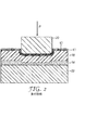
提供される物品及び方法は、本開示に添付する図及び図面によって更に例示することができる。図3は、提供される研磨物品の実施形態の概略断面図であり、ミクロ構造は、可撓性裏材の第2の表面の一部であり、角錐又は角錘の隆線を含む。図3は、可撓性裏材308を含む研磨物品300の実施形態である。研磨材層302(バインダー中に保持される研磨粒子を含む)は、可撓性裏材308の第1の主表面上に配置される。その第2の主表面の少なくとも一部の上に可撓性裏材308は、陥凹部を有するミクロ構造306を含む。接着剤305は、実質的に陥凹部内に位置する。この実施形態では、ミクロ構造の断面は、陥凹部によって画定されるように、V字型である。研磨される表面を含む被加工物320は、研磨材層302に接触し、被加工物320を研磨するために研磨物品300に対して移動する。負荷Pは、図2に示すように被加工物320に印加される。負荷Pは、剛性の基材312によるミクロ構造306の少なくとも一部の直接接触によって支持され、それにより、接着剤層の変形を、除去できないとしても最低限に抑え、被加工物320の縁部のクラウニング又は丸みを除去できないとしても最低限に抑える。
The provided articles and methods can be further illustrated by the figures and drawings attached to this disclosure. FIG. 3 is a schematic cross-sectional view of an embodiment of the provided abrasive article, wherein the microstructure is part of the second surface of the flexible backing and includes a pyramid or pyramidal ridge. FIG. 3 is an embodiment of an
図4は、提供される研磨物品の別の実施形態の概略断面図である。研磨物品400は、可撓性裏材408を含む。研磨材層402(バインダー中に保持される研磨粒子を含む)は、可撓性裏材408の第1の主表面の上に配置される。その第2の主表面の少なくとも一部の上に、可撓性裏材408は、陥凹部を有する複製されたミクロ構造406を含む。接着剤405は、実質的に陥凹部内に位置する。ミクロ構造の形状は、図3に示す実施形態のものと同じである。しかしながら、図4に示す実施形態では、複製されたミクロ構造406は分離された裏材(図示せず)の上に形成され、次いで可撓性裏材408に一体的に結合される。研磨される表面を含む被加工物420は、被加工物420を研磨するために研磨物品400に対して移動する研磨材層402に接触する。負荷Pは、図2に示すように、被加工物420に印加される。負荷Pは、剛性の基材412による複製されたミクロ構造406の少なくとも一部の直接接触によって支持され、それにより、接着剤層の変形を、除去できないとしても最低限に抑え、被加工物420の縁部のクラウニング又は丸みを、除去できないとしても最低限に抑える。
FIG. 4 is a schematic cross-sectional view of another embodiment of the provided abrasive article. The
図5は、提供される研磨物品の別の実施形態の概略断面図であって、複製されたミクロ構造は、切頭角錐又は角錘の隆線を含む。図5は、可撓性裏材508を含む研磨物品500の実施形態である。研磨材層502(バインダー中に保持される研磨粒子を含む、図示せず)は、可撓性裏材508の第1の主表面上に配置される。その第2の主表面の少なくとも一部の上に、可撓性裏材508は、陥凹部を有する複製されたミクロ構造506を含む。接着剤505は、実質的に陥凹部内に位置する。この実施形態では、複製されたミクロ構造の断面は、陥凹部によって画定されるように、切頭されたV字型である。切頭されたミクロ構造は、可撓性裏材508と剛性の基材512との間の接触面積を増やす平坦部を有する。これは、研磨の間、より負荷に耐える支持を提供する。研磨される表面を含む被加工物520は、被加工物520を研磨するために研磨物品500に対して移動する研磨材層502に接触する。負荷Pは、図2に示すように、被加工物520に印加される。負荷Pは、剛性の基材512による複製されたミクロ構造506の少なくとも一部の直接接触によって支持され、それにより、接着剤層の変形を、除去できないとしても最低限に抑え、被加工物520の縁部のクラウニング又は丸みを除去できないとしても最低限に抑える。
FIG. 5 is a schematic cross-sectional view of another embodiment of the provided abrasive article, wherein the replicated microstructure includes a truncated pyramid or pyramidal ridge. FIG. 5 is an embodiment of an
図6は、提供される研磨物品の更に別の実施形態の概略断面図であり、複製されたミクロ構造は直方体又は直方体の隆線である。複製されたミクロ構造の断面は、陥凹部によって画定されるように、長方形の形状である。図6は、可撓性裏材608を含む研磨物品600の実施形態である。研磨材層602(バインダー中に保持される研磨粒子を含む)は、可撓性裏材608の第1の主表面上に配置される。その第2の主表面の少なくとも一部の上に、可撓性裏材608は、陥凹部を有する複製されたミクロ構造606を含む。接着剤605は、実質的に陥凹部内に位置する。直方体のミクロ構造は、可撓性裏材608と剛性の基材612との間の接触面積を増やす平坦部を有する。これは、研磨の間、より負荷に耐える支持を提供する。研磨される表面を含む被加工物620は、被加工物620を研磨するために研磨物品600に対して移動する研磨材層602に接触する。負荷Pは、図2に示すように被加工物620に印加される。負荷Pは、剛性の基材612による複製されたミクロ構造606の少なくとも一部の直接接触によって支持され、それにより、接着剤層の変形を、除去できないとしても最低限に抑え、被加工物620の縁部のクラウニング又は丸みを除去できないとしても最低限に抑える。
FIG. 6 is a schematic cross-sectional view of yet another embodiment of the provided abrasive article, wherein the replicated microstructure is a cuboid or a cuboid ridge. The cross section of the replicated microstructure is rectangular in shape, as defined by the recess. FIG. 6 is an embodiment of an
本発明の目的及び利点は、以下の実施例によって更に例示されるが、これらの実施例において列挙された特定の材料及びその量は、他の諸条件及び詳細と同様に、本発明を過度に制限するものと解釈されるべきではない。 The objects and advantages of this invention are further illustrated by the following examples, which are not intended to limit the particular materials and amounts listed in these examples, as well as other conditions and details. It should not be construed as limiting.
(試験方法)
(ラッピング手順)
3つのAlTiCクーポン(2.40cm×0.20cm×0.5cm)を、Lapmasterモデル15(Lapmaster International LLC(Mount Prospect,Illinois)から入手可能)のラッピング工具を使用して同時にラッピングした。研磨物品を備えたプラテンをこの工具の基部に取り付けた。直径15cm×1mmのAlTiCウェーハを、2液式エポキシ系接着剤、SCOTCHWELD DP100(3M Company(St.Paul,Minnesota)から入手可能)接着剤を使用して、Lapmasterモデル15の直径14.0cm(5.5インチ)のリングの上面に載置した。同じエポキシ系接着剤を使用して、3つのAlTiCクーポンをAlTiCウェーハ表面に載置した。クーポンを、ウェーハの半径4.5mmに沿って均等に間隔を置いて、すなわち、長さが半径に垂直である状態で互いに約120°離して載置した。2.40cm×0.20cmの表面がウェーハに載置されるようにクーポンを載置した。ラッピング条件は、ヘッドの回転20rpm、プラテンの回転40rpm及び3時間のラッピング時間であった。最初の1時間の間、ヘッドに2kgの荷重を加え、2番目の1時間の間4kgの荷重を加え、3番目の1時間の間6kgの荷重を加えた。AlTiCクーポンを、研磨で覆われたプラテンの外径及び内径の範囲内である経路で回転させた。ラップ液を使用し、3時間のプロセス全体を通して0.36g/分の速度で無水エチレングリコールをプラテン上に滴下した。
(Test method)
(Wrapping procedure)
Three AlTiC coupons (2.40 cm x 0.20 cm x 0.5 cm) were simultaneously wrapped using a Lapping Master Model 15 (available from Lapmaster International LLC (Mount Prospect, Illinois)). A platen with an abrasive article was attached to the base of the tool. A 15 cm × 1 mm diameter AlTiC wafer was prepared using a two-part epoxy adhesive, SCOTCHWELD DP100 (available from 3M Company (St. Paul, Minnesota)), 14.0 cm diameter of Lapmaster model 15 (5 .5 inch) ring. Three AlTiC coupons were mounted on the AlTiC wafer surface using the same epoxy-based adhesive. The coupons were placed approximately 120 ° apart from each other evenly spaced along the 4.5 mm radius of the wafer, ie, with the length perpendicular to the radius. The coupon was placed so that the surface of 2.40 cm × 0.20 cm was placed on the wafer. The lapping conditions were a head rotation of 20 rpm, a platen rotation of 40 rpm and a lapping time of 3 hours. A load of 2 kg was applied to the head during the first hour, a load of 4 kg was applied during the second hour, and a load of 6 kg was applied during the third hour. The AlTiC coupon was rotated in a path that was within the outer and inner diameters of the platen covered with polish. Using a lapping solution, anhydrous ethylene glycol was dropped onto the platen at a rate of 0.36 g / min throughout the 3 hour process.
(クラウン測定の手順)
AlTiCクーポンの平坦度の測定を、表面形状測定装置、モデルP16(KLA−Tencor Corporation(Milpitas,California)から入手可能)を使用してラッピング後に行った。それぞれのクーポンの0.2cm幅を横切って、表面形状測定装置を4回走査させた。4回の走査は、クーポンの長さに沿って約0.5cmのインクリメントで取られた。クラウンは、所与の表面形状測定装置の走査の最大高さと最小高さとの間の差として定義される。次いで、3つのクーポンから得た12の測定値を平均して、クラウンの平均値を得た。
(Crown measurement procedure)
The flatness of the AlTiC coupons was measured after lapping using a surface profile measuring device, model P16 (available from KLA-Tencor Corporation (Milpitas, Calif.)). The surface profile measuring device was scanned four times across the 0.2 cm width of each coupon. Four scans were taken in approximately 0.5 cm increments along the length of the coupon. Crown is defined as the difference between the maximum and minimum height of a given profilometer scan. The 12 measurements from the three coupons were then averaged to obtain an average crown value.
(陥凹部を備えるミクロ構造を有する裏材の製作)
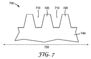
幅25.25インチ(64.1cm)、直径12インチ(30.5cm)の銅表面のスチールロールは、ミクロ構造の間に陥凹部を備える一連のミクロ構造を有する表面を作製するために、ダイヤモンドの旋盤で切削された。ミクロ構造ロール表面700の、ロールの小さい区域740の断面図を、図7に示す。陥凹部710は、ロールの円周に沿って、破線の両頭矢印730で例示されるロール軸方向730に垂直に延びるように切削される。これは、円周に沿っても延びる一連のミクロ構造の特徴720を製造する。陥凹部710の平均深さは、1.3ミル(33.0μm)であった。ミクロ構造付きの特徴720の基部の平均幅は、1.0ミル(15.4μm)であった。ミクロ構造付きの特徴720のベース間の平均距離は、0.48ミル(12.1μm)であった。ミクロ構造付きの特徴720は、特徴の頂部で測定した平均内角が約110°の台形の形状であった。ダイヤモンドの旋盤で切削した後、ロールはイソプロピルアルコールで油を除去され、表面を清浄にするためにアルカリ性溶液が使用された。無電解ニッケルめっきプロセスを使用して、スチールロールの銅表面は、表面を酸化から保護するためにニッケルめっきされた。
(Manufacture of a backing material having a microstructure with a recess)
A steel roll on a copper surface with a width of 25.25 inches (64.1 cm) and a diameter of 12 inches (30.5 cm) is used to create a surface having a series of microstructures with recesses between the microstructures. Was cut with a lathe. A cross-sectional view of the
このロールは、陥凹部を有するミクロ構造表面、隆線を裏材上に作成するための、連続的な成型及び硬化プロセスの金型として使用された。この成型及び硬化プロセスでは、幅23インチ(58.4cm)×厚さ0.005インチ(127マイクロメートル)のポリエステルフィルムが裏材として使用された。光重合可能なアクリレート樹脂が、金型に塗布され、幅約20インチ(50.8cm)で、ロールの長さに沿ってコーティングされた。このアクリレート樹脂は、75重量%脂肪族ウレタンジアクリレート(PHOTOMER 6210の商品名でCognis Corporation(Cincinnati,OH)から入手可能)、24重量%1,6ヘキサンジオールジアクリレート(SR238の商品名でSartomer Company,Inc.(Exton,PA)から入手可能)、及び1重量%光開始剤(LUCIRIN TPOの商品名でBASF Corp.(Charlotte,NC)から入手可能)である。裏材は、金型のアクリレートがコーティングされた区域に引き続いて適用された。アクリレート樹脂は、ロールのミクロ構造の陥凹部の中にある間に、裏材を通してUV硬化された。次いで、裏材は、金型から剥がされた。硬化したアクリル樹脂を、裏材に付着させ、金型から抜いて、ミクロ構造表面を製造した。裏材のミクロ構造のウェブを横切る図に対応する断面図が図8に示される。図8は、裏材840の表面上に陥凹部810及びミクロ構造の特徴820を備えるミクロ構造の裏材表面800を示す。ウェブを横切る方向830を示す。裏材の複製されたミクロ構造の表面は、金型のものと逆のミクロ構造を有する。陥凹部810の平均深さは、1.3ミル(33.0μm)であった。ミクロ構造付きの特徴基部820の平均幅は、1.0ミル(15.4μm)であった。ミクロ構造付きの特徴720のベース間の平均距離は、0.48ミル(12.1μm)であった。ミクロ構造付きの特徴720は、特徴の底部で測定した平均外角が約100°の台形の形状であった。これらの間のミクロ構造及び対応する陥凹部は、ウェブのダウンウェブ方向(down-web direction)に続く。
This roll was used as a mold for a continuous molding and curing process to create a microstructured surface with depressions, ridges on a backing. In this molding and curing process, a polyester film 23 inches (58.4 cm) wide by 0.005 inches (127 micrometers) thick was used as the backing. A photopolymerizable acrylate resin was applied to the mold and coated approximately 20 inches wide (50.8 cm) along the length of the roll. This acrylate resin is 75% by weight aliphatic urethane diacrylate (available from Cognis Corporation (Cincinnati, OH) under the trade name PHOTOMER 6210), 24% by weight 1,6 hexanediol diacrylate (Sartomer Company under the trade name SR238). , Inc. (available from Exton, PA)), and 1 wt% photoinitiator (available from BASF Corp. (Charlotte, NC) under the trade name LUCIRIN TPO). The backing was subsequently applied to the acrylate coated area of the mold. The acrylate resin was UV cured through the backing while in the recess of the roll microstructure. The backing was then peeled away from the mold. The cured acrylic resin was adhered to the backing and removed from the mold to produce a microstructured surface. A cross-sectional view corresponding to the view across the microstructured web of the backing is shown in FIG. FIG. 8 shows a
(実施例)
20インチ(50.8cm)×20インチ(50.8cm)シートのミクロ構造の表面を備える上記の裏材が、18インチ(45.7cm)×21インチ(53.3cm)×0.625インチ(0.159cm)のアルミニウムプレートの上に、ミクロ構造の表面がアルミニウムプレートと向き合うようにテープ止めされた。供給元の仕様に従って混合された1gの3M SCOTCH−Wel Epoxy B/A接着剤(3M Company(St Paul,MN)から入手可能)と3gのメチルエチルケトン(MEK)との溶液が調製された。溶液は、ポリエステル裏材上に注がれ、ゴムローラーを使用して裏材の表面にわたって広げられた。溶媒が蒸発し、エポキシ接着剤が表面を均一な様式で覆うように、表面は繰り返しロールされた。米国特許第6,645,624号(Adefrisら)に従って調製され、38マイクロメートル未満に篩分けされた、1マイクロメートルのダイヤモンド/シリカを50/50重量%含む10グラムの研磨複合材粒子が、縁部に沿って線状にエポキシ接着剤上に注がれた。アルミニウムプレート及びコーティングされた裏材は、45°の角度に保持され、粒子が転がって粘着性のある樹脂をコーティングするように緩やかに軽く叩かれた。この手順は、裏材が完全なコーティングを収容するまで繰り返された。次いで、シートは、垂直に保持され、緩い粒子を取り除くために激しく叩かれた。次いで、拘束された研磨剤は、シリコーン剥離ライナーのシートで覆われ、粒子をエポキシ接着剤の中に単一平面内で押し込むようにゴムのハンドローラーでロールされた。コーティングは、室温で12時間の間硬化され、その後70℃で更に2時間硬化された。
(Example)
The above backing with a microstructured surface of 20 inches (50.8 cm) x 20 inches (50.8 cm) sheet is 18 inches (45.7 cm) x 21 inches (53.3 cm) x 0.625 inches ( A 0.159 cm) aluminum plate was taped with the microstructured surface facing the aluminum plate. A solution of 1 g of 3M SCOTCH-Wel Epoxy B / A adhesive (available from 3M Company (St Paul, MN)) and 3 g of methyl ethyl ketone (MEK) mixed according to the supplier's specifications was prepared. The solution was poured onto a polyester backing and spread over the surface of the backing using a rubber roller. The surface was rolled repeatedly so that the solvent evaporated and the epoxy adhesive covered the surface in a uniform manner. 10 grams of abrasive composite particles, prepared according to US Pat. No. 6,645,624 (Adefris et al.) And sieved to less than 38 micrometers, containing 50/50 wt% of 1 micrometer diamond / silica, It was poured onto the epoxy adhesive in a line along the edge. The aluminum plate and coated backing were held at a 45 ° angle and gently tapped so that the particles rolled and coated the tacky resin. This procedure was repeated until the backing contained the complete coating. The sheet was then held vertically and struck vigorously to remove loose particles. The constrained abrasive was then covered with a sheet of silicone release liner and rolled with a rubber hand roller to push the particles into the epoxy adhesive in a single plane. The coating was cured for 12 hours at room temperature and then for an additional 2 hours at 70 ° C.
次いで研磨材層は、固定するサイズ樹脂コーティングによってスプレーコーティングされた。サイズコーティング樹脂溶液は、4gの2−ブタノン中30重量%のフェノキシ樹脂溶液(YP−50Sの商品名でTohto Kasei Co.Lt.Inabata America Corp(New York,NY)から入手可能)と、2.3gのMEK中35重量%のポリエステルポリウレタン樹脂溶液(ネオペンチルグリコール21重量%、ポリカプロラクトン29重量%、及びメチレンジイソシアネート50重量%内部で合成)と、1.1gの高分子イソシアネート(Mondur MRSの商品名でBayer Chemical(Pittsburgh,PA)から入手可能)と、40gのMEKと、10gのシクロヘキサノンと、からなっていた。サイズコーティング樹脂溶液は、エアゾール容器内に入れられた。研磨剤表面は、良好に換気されたフード内で、約60秒間、又は表面が濡れているように見えるまでサイズコーティング溶液でスプレーされた。次いで、アルミニウムプレート及び研磨物品は、炉内で70℃で17時間加熱された。冷却後、ミクロ構造を備えるフィルムは反転され、これにより研磨剤表面はアルミニウムプレートに接触し、ミクロ構造表面は露出した。次いで、架橋されていない、アクリレート系の、0.0009インチ(22.9マイクロメートル)の公称厚さを有する、シリコン処理されたクラフト紙の剥離ライナー上にコーティングされた感圧接着剤の層が、ゴムローラーを使用して裏材のミクロ構造表面に手で積層された。研磨物品の剥離ライナーを取り外し、研磨物品は、ゴムローラーを使用して、標準CNC切断技法を用いて作製された、外径16インチ(40.6cm)、内径8インチ(20.3cm)及び厚さ1.5インチ(3.8cm)の平らで環状形状のアルミニウムプラテンに、手で積層された。 The abrasive layer was then spray coated with a fixed size resin coating. The size coating resin solution is 4 g of 30% by weight phenoxy resin solution in 2-butanone (available from Tohto Kasei Co. Ltd. Inbata America Corp (New York, NY) under the trade name YP-50S); 35% by weight polyester polyurethane resin solution in 3 g MEK (synthesized inside 21% by weight neopentyl glycol, 29% by weight polycaprolactone and 50% by weight methylene diisocyanate) and 1.1 g high molecular isocyanate (Mondur MRS product) By name Bayer Chemical (available from Pittsburgh, Pa.), 40 g MEK and 10 g cyclohexanone. The size coating resin solution was placed in an aerosol container. The abrasive surface was sprayed with the size coating solution in a well ventilated hood for about 60 seconds or until the surface appeared wet. The aluminum plate and abrasive article were then heated in a furnace at 70 ° C. for 17 hours. After cooling, the film with the microstructure was inverted so that the abrasive surface contacted the aluminum plate and the microstructured surface was exposed. A non-crosslinked, acrylate-based, pressure-sensitive adhesive layer coated on a siliconized kraft paper release liner having a nominal thickness of 0.0009 inches (22.9 micrometers) is then applied. Laminated by hand on the microstructured surface of the backing using a rubber roller. The abrasive article release liner was removed and the abrasive article was made using a standard CNC cutting technique using a rubber roller, with an outer diameter of 16 inches (40.6 cm), an inner diameter of 8 inches (20.3 cm) and a thickness. It was manually laminated to a 1.5 inch (3.8 cm) flat, annular aluminum platen.
次いで研磨物品を備えるプラテンは、23インチ(58.4cm)×18インチ(45.7cm)×3/8インチ(0.95cm)の石英シートの上に研磨面を下にして置かれた。10.7kgの重量の同一のプラテンが、取り付けられた研磨剤を備える第1のプラテンの上に置かれ、この積み重ね全体が炉内で70℃で48時間加熱された。この積み重ねは、炉から取り出され、第2のプラテンは、この積み重ねから除去され、取り付けられた研磨物品を備えるプラテンは、研磨剤がまだ石英プレートに接触している間に冷却された。研磨物品は、プラテンの寸法に合うようにカミソリの刃でトリミングされた上記のラッピング手順及びクラウン測定値手順に従うと、3つのAlTiCクーポンの平均クラウンは、0.9マイクロインチ(0.0229μm)であった。 The platen with the abrasive article was then placed on a 23 inch (58.4 cm) × 18 inch (45.7 cm) × 3/8 inch (0.95 cm) quartz sheet with the polishing surface down. The same platen weighing 10.7 kg was placed on the first platen with the attached abrasive and the entire stack was heated in an oven at 70 ° C. for 48 hours. The stack was removed from the furnace, the second platen was removed from the stack, and the platen with the attached abrasive article was cooled while the abrasive was still in contact with the quartz plate. The abrasive article was trimmed with a razor blade to fit the dimensions of the platen and the average crown of the three AlTiC coupons was 0.9 microinches (0.0229 μm) according to the above wrapping and crown measurement procedures. there were.
本発明の範囲及び趣旨から逸脱しない本発明の様々な変更や改変は、当業者には明らかとなるであろう。本発明は、本明細書で述べる例示的な実施形態及び実施例によって不当に限定されるものではないこと、また、こうした実施例及び実施形態は、本明細書において以下に記述する特許請求の範囲によってのみ限定されると意図する本発明の範囲に関する例示のためにのみ提示されることを理解すべきである。本開示に引用される参照文献はすべて、その全体が本明細書に組み込まれる。 Various changes and modifications of this invention will become apparent to those skilled in the art without departing from the scope and spirit of this invention. The present invention is not unduly limited by the exemplary embodiments and examples described herein, and such examples and embodiments are claimed in the claims herein below. It should be understood that this is presented only for illustration regarding the scope of the invention, which is intended to be limited only by. All references cited in this disclosure are incorporated herein in their entirety.
以下は、本発明の態様による、複製されたミクロ構造付きの裏材を備える研磨物品及びこれを使用する方法の例示的な実施形態である。 The following are exemplary embodiments of an abrasive article comprising a replicated microstructured backing and method of using the same according to aspects of the present invention.
実施形態1は、対向する第1及び第2の主表面を有する可撓性裏材であって、可撓性裏材の第2の主表面の少なくとも一部が陥凹部を有する複製されたミクロ構造を含む、可撓性裏材と、少なくとも1つのバインダー中に保持される複数の研磨粒子を備える研磨材層であって、可撓性裏材の第1の主表面上に配置される、研磨材層と、接着剤と、を備え、接着剤が、実質的に複製されたミクロ構造の陥凹部内に収容される、研磨物品である。 Embodiment 1 is a flexible backing having opposing first and second major surfaces, wherein at least a portion of the second major surface of the flexible backing has a recessed recess. An abrasive layer comprising a flexible backing comprising a structure and a plurality of abrasive particles held in at least one binder, disposed on a first major surface of the flexible backing. An abrasive article comprising an abrasive layer and an adhesive, wherein the adhesive is contained within a substantially replicated microstructured recess.
実施形態2は、複製されたミクロ構造の少なくとも一部と接触する剛性の基材を更に備える、実施形態1による研磨物品である。 Embodiment 2 is an abrasive article according to embodiment 1, further comprising a rigid substrate in contact with at least a portion of the replicated microstructure.
実施形態3は、接着剤の少なくとも一部に接触する剥離ライナーを更に含む、実施形態1による研磨物品である。 Embodiment 3 is an abrasive article according to embodiment 1 further comprising a release liner that contacts at least a portion of the adhesive.
実施形態4は、可撓性裏材が、高密度クラフト紙、ポリコート紙、金属箔、及びポリマー基材からなる群から選択される、実施形態1による研磨物品である。 Embodiment 4 is an abrasive article according to embodiment 1 wherein the flexible backing is selected from the group consisting of high density kraft paper, polycoated paper, metal foil, and polymer substrate.
実施形態5は、金属箔がアルミニウム、銅、スズ、及び青銅から選択される、実施形態4による研磨物品である。 Embodiment 5 is an abrasive article according to embodiment 4, wherein the metal foil is selected from aluminum, copper, tin, and bronze.
実施形態6は、ポリマー基材が、ポリエステル、ポリカーボネート、ポリプロピレン、ポリエチレン、セルロース、ポリアミド、ポリイミド、ポリシリコーン、及びポリテトラフルオロエチレンからなる群から選択される、実施形態4による研磨物品である。 Embodiment 6 is an abrasive article according to embodiment 4, wherein the polymer substrate is selected from the group consisting of polyester, polycarbonate, polypropylene, polyethylene, cellulose, polyamide, polyimide, polysilicon, and polytetrafluoroethylene.
実施形態7は、研磨粒子が、溶融酸化アルミニウム、熱処理酸化アルミニウム、白色溶融酸化アルミニウム、黒色炭化ケイ素、緑色炭化ケイ素、二ホウ化チタン、炭化ホウ素、炭化タングステン、炭化チタン、ダイヤモンド、シリカ、酸化鉄、クロミア、セリア、ジルコニア、チタニア、ケイ酸塩、酸化スズ、立方晶窒化ホウ素、ガーネット、溶融アルミナジルコニア、ゾルゲル研磨粒子、研磨凝塊、金属系微粒子、及びこれらの組み合わせからなる群から選択される、実施形態1による研磨物品である。 In Embodiment 7, the abrasive particles are fused aluminum oxide, heat treated aluminum oxide, white molten aluminum oxide, black silicon carbide, green silicon carbide, titanium diboride, boron carbide, tungsten carbide, titanium carbide, diamond, silica, iron oxide , Chromia, ceria, zirconia, titania, silicate, tin oxide, cubic boron nitride, garnet, fused alumina zirconia, sol-gel abrasive particles, abrasive agglomerates, metal-based particulates, and combinations thereof 1 is an abrasive article according to Embodiment 1.
実施形態8は、可撓性裏材が、約0.5GPaより大きいヤング率を有する、実施形態1による研磨物品である。 Embodiment 8 is an abrasive article according to embodiment 1, wherein the flexible backing has a Young's modulus greater than about 0.5 GPa.
実施形態9は、可撓性裏材が、約2.0GPaより大きいヤング率を有する、実施形態8による研磨物品である。 Embodiment 9 is the abrasive article according to embodiment 8, wherein the flexible backing has a Young's modulus greater than about 2.0 GPa.
実施形態10は、複製されたミクロ構造が、ロッド、三角形、角錐、切頭角錐、円錐、切頭円錐、キューブコーナー、直方体、球、又は楕円体を含む形状を有する、実施形態1による研磨物品である。
実施形態11は、複製されたミクロ構造が、隆線を含む形状を有する実施形態1による、研磨物品である。 Embodiment 11 is an abrasive article according to embodiment 1 in which the replicated microstructure has a shape that includes ridges.
実施形態12は、接着剤が、感圧性接着剤、ホットメルト接着剤、及び硬化性液体接着剤からなる群から選択される、実施形態1による研磨物品である。
実施形態13は、接着剤が、複製されたミクロ構造の陥凹部の体積の約25体積パーセント超約120体積パーセント未満を占める、実施形態1による研磨物品である。
実施形態14は、研磨される被加工物を提供することと、被加工物を研磨物品と接触させることであって、研磨物品が、対向する第1及び第2の主表面を有し、第2の主表面の少なくとも一部が陥凹部を有する複製されたミクロ構造を含む、可撓性裏材と、少なくとも1つのバインダー中に保持される複数の研磨粒子を備え、可撓性裏材の第1の主表面上に配置されている、研磨材層と、接着剤と、複製されたミクロ構造の少なくとも一部と接触する剛性の基材と、を備え、接着剤が複製されたミクロ構造の陥凹部内に実質的に収容される、接触させることと、研磨物品を被加工物に対して移動することと、を含む、研磨方法である。
実施形態15は、研磨粒子が、溶融酸化アルミニウム、熱処理酸化アルミニウム、白色溶融酸化アルミニウム、黒色炭化ケイ素、緑色炭化ケイ素、二ホウ化チタン、炭化ホウ素、炭化タングステン、炭化チタン、ダイヤモンド、シリカ、酸化鉄、クロミア、セリア、ジルコニア、チタニア、ケイ酸塩、酸化スズ、立方晶窒化ホウ素、ガーネット、溶融アルミナジルコニア、ゾルゲル研磨粒子、研磨凝塊、金属系微粒子、及びこれらの組み合わせからなる群から選択される、実施形態14による研磨方法である。
In Embodiment 15, the abrasive particles are fused aluminum oxide, heat treated aluminum oxide, white molten aluminum oxide, black silicon carbide, green silicon carbide, titanium diboride, boron carbide, tungsten carbide, titanium carbide, diamond, silica, iron oxide , Chromia, ceria, zirconia, titania, silicate, tin oxide, cubic boron nitride, garnet, fused alumina zirconia, sol-gel abrasive particles, abrasive agglomerates, metal-based particulates, and combinations thereof The polishing method according to
実施形態16は、複製されたミクロ構造が、ロッド、三角形、角錐、切頭角錐、円錐、切頭円錐、キューブコーナー、直方体、球、又は楕円体を含む形状を有する、実施形態14による研磨方法である。
Embodiment 16 is the polishing method according to
実施形態17は、複製されたミクロ構造が、隆線を含む形状を有する、実施形態14による研磨方法である。
Embodiment 17 is the polishing method according to
実施形態18は、接着剤が、感圧性接着剤、ホットメルト接着剤、及び硬化性液体接着剤からなる群から選択される、実施形態14による研磨方法である。
実施形態19は、接着剤が、複製されたミクロ構造の陥凹部の体積の約25体積パーセント超約120体積パーセント未満を占める、実施形態14による研磨方法である。
Embodiment 19 is the polishing method according to
実施形態20は、接着剤上に配置された剥離ライナーを更に備える、実施形態14による研磨方法である。
以上、好適な実施形態の説明を目的として具体的な実施形態を本明細書に例示、及び説明したが、同様の目的を達成することが予想される広範な代替的かつ/又は同等の実施の態様を、本発明の範囲を逸脱することなく、図示及び説明された特定の実施形態に置き換えることができる点は当業者には認識されるであろう。機械的、電気機械的、及び電気的分野における当業者であれば、本発明が広範な実施形態で実施し得る点は直ちに認識されるであろう。本願は、本明細書で論じた好ましい実施形態のいかなる採用又は変型をも包含することを意図したものである。したがって、本発明が特許請求の範囲及びその均等物によってのみ限定される点を明示するものである。 Although specific embodiments have been illustrated and described herein for the purpose of illustrating the preferred embodiments, there are a wide variety of alternative and / or equivalent implementations that are expected to achieve similar objectives. Those skilled in the art will recognize that aspects may be substituted for the specific embodiments illustrated and described without departing from the scope of the invention. Those skilled in the mechanical, electromechanical, and electrical arts will readily appreciate that the present invention may be implemented in a wide variety of embodiments. This application is intended to cover any adaptations or variations of the preferred embodiments discussed herein. Therefore, it is manifestly intended that the present invention be limited only by the claims and the equivalents thereof.
Claims (20)
少なくとも1つのバインダー中に保持される複数の研磨粒子を備える研磨材層であって、前記可撓性裏材の前記第1の主表面上に配置される、研磨材層と、
接着剤と、を備え、
前記接着剤が、実質的に前記複製されたミクロ構造の前記陥凹部内に収容される、研磨物品。 A flexible backing having opposing first and second major surfaces, wherein at least a portion of the second major surface of the flexible backing includes a replicated microstructure having a recess. A flexible backing;
An abrasive layer comprising a plurality of abrasive particles retained in at least one binder, the abrasive layer disposed on the first major surface of the flexible backing;
An adhesive, and
An abrasive article, wherein the adhesive is substantially contained within the recess of the replicated microstructure.
前記被加工物を研磨物品と接触させることであって、前記研磨物品が、
対向する第1及び第2の主表面を有し、前記第2の主表面の少なくとも一部が陥凹部を有する複製されたミクロ構造を含む、可撓性裏材と、
少なくとも1つのバインダー中に保持される複数の研磨粒子を備え、前記可撓性裏材の前記第1の主表面上に配置されている、研磨材層と、
接着剤と、
前記複製されたミクロ構造の少なくとも一部と接触する剛性の基材と、を備え、
前記接着剤が前記複製されたミクロ構造の前記陥凹部内に実質的に収容される、接触させることと、
前記研磨物品を前記被加工物に対して移動することと、を含む、研磨方法。 Providing a workpiece to be polished;
Contacting the workpiece with an abrasive article, wherein the abrasive article comprises:
A flexible backing having a replicated microstructure having opposing first and second major surfaces, at least a portion of the second major surface having a recess;
An abrasive layer comprising a plurality of abrasive particles held in at least one binder and disposed on the first major surface of the flexible backing;
Glue and
A rigid substrate in contact with at least a portion of the replicated microstructure;
Contacting the adhesive substantially contained within the recessed portion of the replicated microstructure;
Moving the abrasive article relative to the workpiece.
Applications Claiming Priority (3)
| Application Number | Priority Date | Filing Date | Title |
|---|---|---|---|
| US201161436407P | 2011-01-26 | 2011-01-26 | |
| US61/436,407 | 2011-01-26 | ||
| PCT/US2012/022142 WO2012102978A1 (en) | 2011-01-26 | 2012-01-23 | Abrasive article with replicated microstructured backing and method of using same |
Publications (2)
| Publication Number | Publication Date |
|---|---|
| JP2014508650A true JP2014508650A (en) | 2014-04-10 |
| JP2014508650A5 JP2014508650A5 (en) | 2015-02-12 |
Family
ID=45755505
Family Applications (1)
| Application Number | Title | Priority Date | Filing Date |
|---|---|---|---|
| JP2013551260A Pending JP2014508650A (en) | 2011-01-26 | 2012-01-23 | Abrasive article comprising a backing having a replicated microstructure and method of using the same |
Country Status (7)
| Country | Link |
|---|---|
| US (1) | US20130295821A1 (en) |
| JP (1) | JP2014508650A (en) |
| KR (1) | KR20140018880A (en) |
| CN (1) | CN103328158A (en) |
| SG (1) | SG191978A1 (en) |
| TW (1) | TW201238716A (en) |
| WO (1) | WO2012102978A1 (en) |
Cited By (1)
| Publication number | Priority date | Publication date | Assignee | Title |
|---|---|---|---|---|
| JP2020511326A (en) * | 2017-02-21 | 2020-04-16 | ダイアマブラッシュ エルエルシーDiamabrush Llc | Sanding screen fixture |
Families Citing this family (11)
| Publication number | Priority date | Publication date | Assignee | Title |
|---|---|---|---|---|
| EP3086903B1 (en) * | 2013-12-23 | 2019-09-11 | 3M Innovative Properties Company | A coated abrasive article maker apparatus |
| CN104369120B (en) * | 2014-09-15 | 2016-11-09 | 西安德谦新材料科技发展有限公司 | A kind of diamond implanted based on grinding unit or CBN grinding tool preparation method |
| CN107000171A (en) * | 2014-11-26 | 2017-08-01 | 3M创新有限公司 | Abrasive product, component and method with clamping material |
| CN104403575B (en) * | 2014-12-23 | 2016-09-21 | 包头市华辰稀土材料有限公司 | A kind of preparation method of high accuracy aluminum oxide polishing powder |
| WO2016209651A1 (en) * | 2015-06-22 | 2016-12-29 | 3M Innovative Properties Company | Abrasive articles, assemblies, and methods with gripping material |
| CN105500186A (en) * | 2016-01-21 | 2016-04-20 | 苏州新美光纳米科技有限公司 | Polishing pad for wafer polishing and self-absorption method thereof |
| CN105751090A (en) * | 2016-04-15 | 2016-07-13 | 常州市金牛研磨有限公司 | Anti-skid strengthened abrasive belt |
| KR102608124B1 (en) * | 2017-08-04 | 2023-11-29 | 쓰리엠 이노베이티브 프로퍼티즈 컴파니 | Microreplicated polished surface with improved coplanarity |
| TWI674947B (en) * | 2018-04-19 | 2019-10-21 | 智勝科技股份有限公司 | Polishing pad, manufacturing method of polishing pad and polishing method |
| CN108747876B (en) * | 2018-06-11 | 2021-03-19 | 河北思瑞恩新材料科技有限公司 | Preparation method of paint surface grinding sand disc |
| US10954803B2 (en) * | 2019-01-17 | 2021-03-23 | Rolls-Royce Corporation | Abrasive coating for high temperature mechanical systems |
Citations (3)
| Publication number | Priority date | Publication date | Assignee | Title |
|---|---|---|---|---|
| JPS5318083A (en) * | 1976-08-04 | 1978-02-18 | Sankyo Rikagaku Co | Grinding instruments of multiilayer structure |
| JPS61297083A (en) * | 1985-06-26 | 1986-12-27 | ノ−トン カンパニ− | Grinding cloth paper |
| JPH06278002A (en) * | 1993-01-28 | 1994-10-04 | Minnesota Mining & Mfg Co <3M> | Polishing device |
Family Cites Families (11)
| Publication number | Priority date | Publication date | Assignee | Title |
|---|---|---|---|---|
| US5152917B1 (en) * | 1991-02-06 | 1998-01-13 | Minnesota Mining & Mfg | Structured abrasive article |
| US5692950A (en) * | 1996-08-08 | 1997-12-02 | Minnesota Mining And Manufacturing Company | Abrasive construction for semiconductor wafer modification |
| JP2003534137A (en) * | 2000-04-28 | 2003-11-18 | スリーエム イノベイティブ プロパティズ カンパニー | Abrasive article and glass grinding method |
| US6632129B2 (en) * | 2001-02-15 | 2003-10-14 | 3M Innovative Properties Company | Fixed abrasive article for use in modifying a semiconductor wafer |
| US6838142B2 (en) * | 2001-05-18 | 2005-01-04 | 3M Innovative Properties Company | Specular laminates |
| US6846232B2 (en) * | 2001-12-28 | 2005-01-25 | 3M Innovative Properties Company | Backing and abrasive product made with the backing and method of making and using the backing and abrasive product |
| CN1411038A (en) * | 2002-05-30 | 2003-04-16 | 株式会社日立制作所 | Polishing method and apparatus |
| US6755878B2 (en) * | 2002-08-02 | 2004-06-29 | 3M Innovative Properties Company | Abrasive articles and methods of making and using the same |
| JP5020333B2 (en) * | 2006-12-20 | 2012-09-05 | スリーエム イノベイティブ プロパティズ カンパニー | Coated abrasive disc and method for making the same |
| EP2101952B1 (en) * | 2006-12-21 | 2013-02-13 | Saint-Gobain Abrasives, Inc. | Abrasive article with cured backsize layer |
| US20100022174A1 (en) * | 2008-07-28 | 2010-01-28 | Kinik Company | Grinding tool and method for fabricating the same |
-
2012
- 2012-01-23 JP JP2013551260A patent/JP2014508650A/en active Pending
- 2012-01-23 CN CN2012800056627A patent/CN103328158A/en active Pending
- 2012-01-23 US US13/979,233 patent/US20130295821A1/en not_active Abandoned
- 2012-01-23 KR KR1020137022016A patent/KR20140018880A/en not_active Application Discontinuation
- 2012-01-23 SG SG2013054051A patent/SG191978A1/en unknown
- 2012-01-23 WO PCT/US2012/022142 patent/WO2012102978A1/en active Application Filing
- 2012-01-30 TW TW101102916A patent/TW201238716A/en unknown
Patent Citations (3)
| Publication number | Priority date | Publication date | Assignee | Title |
|---|---|---|---|---|
| JPS5318083A (en) * | 1976-08-04 | 1978-02-18 | Sankyo Rikagaku Co | Grinding instruments of multiilayer structure |
| JPS61297083A (en) * | 1985-06-26 | 1986-12-27 | ノ−トン カンパニ− | Grinding cloth paper |
| JPH06278002A (en) * | 1993-01-28 | 1994-10-04 | Minnesota Mining & Mfg Co <3M> | Polishing device |
Cited By (2)
| Publication number | Priority date | Publication date | Assignee | Title |
|---|---|---|---|---|
| JP2020511326A (en) * | 2017-02-21 | 2020-04-16 | ダイアマブラッシュ エルエルシーDiamabrush Llc | Sanding screen fixture |
| JP6991248B2 (en) | 2017-02-21 | 2022-01-12 | ダイアマブラッシュ エルエルシー | Sanding screen equipment |
Also Published As
| Publication number | Publication date |
|---|---|
| US20130295821A1 (en) | 2013-11-07 |
| CN103328158A (en) | 2013-09-25 |
| WO2012102978A1 (en) | 2012-08-02 |
| KR20140018880A (en) | 2014-02-13 |
| SG191978A1 (en) | 2013-08-30 |
| TW201238716A (en) | 2012-10-01 |
Similar Documents
| Publication | Publication Date | Title |
|---|---|---|
| JP2014508650A (en) | Abrasive article comprising a backing having a replicated microstructure and method of using the same | |
| CN112566753B (en) | Structured abrasive article and method of making the same | |
| KR101643798B1 (en) | Structured abrasive article and method of using the same | |
| JP5555453B2 (en) | Abrasive product, method for producing and using the same | |
| EP2470331B1 (en) | Structured abrasive article and method of using the same | |
| JP5340966B2 (en) | Abrasive article having supersize coating and manufacturing method | |
| US20130059506A1 (en) | Fixed abrasive pad with surfactant for chemical mechanical planarization | |
| EP3532249A1 (en) | Structured abrasive articles and methods of making the same | |
| JP2007505759A (en) | Structured abrasive article | |
| JP6623153B2 (en) | Structured abrasive article and method of use | |
| JP2001505489A5 (en) | ||
| JP2009534202A (en) | Embossed structure abrasive article and method for producing and using the same | |
| JP6792988B2 (en) | Polishing pad and its manufacturing method, and manufacturing method of polished products | |
| JP2007505757A (en) | Structured abrasive article | |
| JP2005166712A (en) | Polishing pad for cmp and polishing method | |
| JP2007505756A (en) | Method for producing coated abrasive | |
| US20210024799A1 (en) | Structured abrasives containing polishing materials for use in the home | |
| WO2024090474A1 (en) | Sheet-form polishing article | |
| JP2023148907A (en) | Method for manufacturing polishing pad, and polishing pad | |
| JP2023124048A (en) | Polishing pad and method for manufacturing the same | |
| RU2173251C1 (en) | Structuralized abrasives with coherent functional powders |
Legal Events
| Date | Code | Title | Description |
|---|---|---|---|
| A521 | Written amendment |
Free format text: JAPANESE INTERMEDIATE CODE: A523 Effective date: 20141217 |
|
| A621 | Written request for application examination |
Free format text: JAPANESE INTERMEDIATE CODE: A621 Effective date: 20141217 |
|
| A131 | Notification of reasons for refusal |
Free format text: JAPANESE INTERMEDIATE CODE: A131 Effective date: 20150825 |
|
| A02 | Decision of refusal |
Free format text: JAPANESE INTERMEDIATE CODE: A02 Effective date: 20160308 |