JP2014239380A - Abnormality detection device for electromagnetic device drive device - Google Patents
Abnormality detection device for electromagnetic device drive device Download PDFInfo
- Publication number
- JP2014239380A JP2014239380A JP2013121891A JP2013121891A JP2014239380A JP 2014239380 A JP2014239380 A JP 2014239380A JP 2013121891 A JP2013121891 A JP 2013121891A JP 2013121891 A JP2013121891 A JP 2013121891A JP 2014239380 A JP2014239380 A JP 2014239380A
- Authority
- JP
- Japan
- Prior art keywords
- voltage
- potential
- output terminal
- abnormality
- determination
- Prior art date
- Legal status (The legal status is an assumption and is not a legal conclusion. Google has not performed a legal analysis and makes no representation as to the accuracy of the status listed.)
- Pending
Links
Images


Abstract
Description
本発明は、電磁装置を駆動する装置の異常検出装置に関する。 The present invention relates to an abnormality detection device for a device that drives an electromagnetic device.
電磁負荷の電源電圧の側にハイサイドスイッチ素子が接続されると共に、電磁負荷のグランドの側にローサイドスイッチ素子が接続された駆動装置の故障診断として、駆動を開始した後、電磁負荷の電流値が所定の閾値を超えるまでの時間を測定し、その測定結果によりスイッチ素子のレアショートを検出する、という技術がある(例えば、特許文献1参照)。レアショートとは、所定のインピーダンスを持った状態でのショートである。 Current value of the electromagnetic load after starting driving as a failure diagnosis of the drive device in which the high-side switch element is connected to the power supply voltage side of the electromagnetic load and the low-side switch element is connected to the ground side of the electromagnetic load There is a technique of measuring a time until the value exceeds a predetermined threshold, and detecting a rare short of the switch element based on the measurement result (see, for example, Patent Document 1). A rare short is a short in a state having a predetermined impedance.
上記文献の技術は、電磁負荷の上流側と下流側との両方にスイッチ素子が設けられる駆動装置を前提としており、電磁負荷の上流側と下流側とのうち、下流側にだけスイッチ素子が設けられるローサイド駆動の駆動装置や、上流側にだけスイッチ素子が設けられるハイサイド駆動の駆動装置には適用できない。また、上記文献の技術では、電磁負荷の駆動を開始してからでないとレアショートを検出することができない上に、電磁負荷に流れる電流を検出するための手段も必要となる。 The technology of the above document is based on a drive device in which switch elements are provided on both the upstream side and the downstream side of the electromagnetic load, and the switch element is provided only on the downstream side of the upstream side and the downstream side of the electromagnetic load. The present invention cannot be applied to a low-side drive device or a high-side drive device in which a switch element is provided only on the upstream side. In addition, in the technique of the above-mentioned document, it is not possible to detect a rare short unless the driving of the electromagnetic load is started, and a means for detecting the current flowing through the electromagnetic load is also required.
一方、上記文献で電磁負荷と言っているのは、実際には、コイルに電流が流れることによって動作する電磁装置(例えばインジェクタ)の、そのコイルのことである。
そして、例えばローサイド駆動の駆動装置においては、電磁装置のコイルの一端が電源の高電位側に接続されると共に、コイルの他端が駆動装置の出力端子に接続され、その出力端子がスイッチ素子を介して電源の低電位側に接続されることで、コイルに電流が流れる。このため、出力端子が電源の低電位側にレアショートして、コイルの両端電位差が、電磁装置の最低動作電圧以上になると、電磁装置が不要に動作してしまうこととなる。
On the other hand, the electromagnetic load in the above document is actually the coil of an electromagnetic device (for example, an injector) that operates when a current flows through the coil.
For example, in a low-side drive device, one end of the coil of the electromagnetic device is connected to the high potential side of the power supply, the other end of the coil is connected to the output terminal of the drive device, and the output terminal is a switch element. By connecting to the low potential side of the power supply via the current flows through the coil. For this reason, if the output terminal is short-circuited to the low potential side of the power supply and the potential difference between both ends of the coil becomes equal to or higher than the minimum operating voltage of the electromagnetic device, the electromagnetic device will operate unnecessarily.
つまり、出力端子のレアショートとしては、電磁装置を駆動しない非駆動期間において、電磁装置の動作には至らないレアショートと、電磁装置が不要に動作してしまうレアショート(以下、このレアショートを、電磁装置の動作には至らないレアショートと区別する場合には、動作誘発レアショートともいう)とがある。しかし、上記文献の技術では、電磁装置の非駆動期間中に動作誘発レアショートを検出することはできない。 In other words, the rare short of the output terminal includes a rare short that does not lead to the operation of the electromagnetic device in a non-driving period in which the electromagnetic device is not driven, and a rare short that causes the electromagnetic device to operate unnecessarily (hereinafter referred to as this rare short). In the case of distinguishing from a rare short that does not lead to the operation of the electromagnetic device, it is also called an action-induced rare short). However, the technique disclosed in the above document cannot detect an operation-induced rare short during the non-driving period of the electromagnetic device.
尚、ハイサイド駆動の駆動装置においては、電磁装置のコイルの一端が電源の低電位側に接続されると共に、コイルの他端が駆動装置の出力端子に接続され、その出力端子がスイッチ素子を介して電源の高電位側にされることで、コイルに電流が流れる。そして、ハイサイド駆動の駆動装置においても、出力端子が電源の高電位側にレアショートして、コイルの両端電位差が、電磁装置の最低動作電圧以上になると、電磁装置が不要に動作してしまうこととなる。また、駆動装置の出力端子が電源の低電位側や高電位側にレアショートすることは、出力端子自体が電源の低電位側や高電位側にレアショートすること以外にも、例えば、その出力端子に接続されたスイッチ素子の端子間がレアショートすることによっても、起こることである。 In the high-side drive device, one end of the coil of the electromagnetic device is connected to the low potential side of the power source, the other end of the coil is connected to the output terminal of the drive device, and the output terminal is a switch element. The current flows through the coil by being set to the high potential side of the power source. Even in a high-side drive device, if the output terminal is short-circuited to the high potential side of the power supply and the potential difference across the coil exceeds the minimum operating voltage of the electromagnetic device, the electromagnetic device will operate unnecessarily. It will be. In addition to the fact that the output terminal of the driving device is short-circuited to the low potential side or the high potential side of the power supply, the output terminal itself is rarely short-circuited to the low potential side or the high potential side of the power supply. This is also caused by a rare short between the terminals of the switch elements connected to the terminals.
そこで、本発明は、ローサイド駆動又はハイサイド駆動の電磁装置駆動装置に用いられると共に、電磁装置の非駆動期間において、電磁装置の不要な動作を招く出力端子のレアショートを検出するのに好適な、異常検出装置の提供を目的としている。 Therefore, the present invention is suitable for detecting a short-circuit of an output terminal that is used in a low-side drive or high-side drive electromagnetic device drive device and causes an unnecessary operation of the electromagnetic device during a non-drive period of the electromagnetic device. The purpose is to provide an abnormality detection device.
第1発明の異常検出装置が用いられる電磁装置駆動装置は、出力電圧が変化し得る電源の高電位側と低電位側との一方である第1電位に、コイルの一端が接続され、該コイルに電流が流れることによって動作する電磁装置の、前記コイルの他端に接続される出力端子と、前記電源の高電位側と低電位側とのうちで前記第1電位とは異なる方である第2電位と前記出力端子との間の電流経路を、オンすることで接続し、オフすることで、前記電流経路を遮断する通電用スイッチと、前記通電用スイッチをオンさせることにより、前記コイルに電流を流す制御手段と、を備える。 In the electromagnetic device driving apparatus in which the abnormality detection device of the first invention is used, one end of a coil is connected to a first potential that is one of a high potential side and a low potential side of a power supply whose output voltage can change, and the coil Of the electromagnetic device that operates when a current flows through the output terminal connected to the other end of the coil, and the first potential is different from the high potential side and the low potential side of the power source. The current path between two potentials and the output terminal is connected by turning it on, and by turning it off, the energizing switch that cuts off the current path and turning on the energizing switch And a control means for flowing current.
第1電位が、電源の高電位側の電位で、第2電位が、電源の低電位側の電位であれば、ローサイド駆動の電磁装置駆動装置ということになり、逆に、第1電位が、電源の低電位側の電位で、第2電位が、電源の高電位側の電位であれば、ハイサイド駆動の電磁装置駆動装置ということになる。 If the first potential is a potential on the high potential side of the power source and the second potential is a potential on the low potential side of the power source, it is an electromagnetic device driving device for low side driving, and conversely, the first potential is If the second potential is a potential on the low potential side of the power source and the potential on the high potential side of the power source, it is an electromagnetic device driving device for high side driving.
そして、第1発明の異常検出装置は、異常判定用電圧発生手段と、電圧判定手段と、異常判定手段と、を備える。
異常判定用電圧発生手段は、前記第1電位を基準にして、該第1電位よりも所定の一定電圧だけ前記第2電位側の電圧を、異常判定用電圧として発生する。
The abnormality detection device according to the first aspect of the present invention includes abnormality determination voltage generation means, voltage determination means, and abnormality determination means.
The abnormality determination voltage generating means generates, as the abnormality determination voltage, a voltage on the second potential side by a predetermined constant voltage from the first potential with reference to the first potential.
電圧判定手段は、前記出力端子の電圧が前記異常判定用電圧よりも前記第2電位側の電圧であるか否かを判定する。
異常判定手段は、前記通電用スイッチがオフされている期間において、前記電圧判定手段により、前記出力端子の電圧が前記異常判定用電圧よりも前記第2電位側の電圧であると判定された場合に、異常が発生していると判定する。
The voltage determination means determines whether or not the voltage at the output terminal is a voltage on the second potential side with respect to the abnormality determination voltage.
The abnormality determination unit is configured to determine that the voltage determination unit determines that the voltage at the output terminal is a voltage on the second potential side with respect to the abnormality determination voltage during the period when the energization switch is off. It is determined that an abnormality has occurred.
つまり、通電用スイッチがオフされている電磁装置の非駆動期間において、出力端子が所定のインピーダンスを持った状態で第2電位にショートした異常であるレアショートが発生していると、電磁装置のコイルの両端に電位差が生じることとなる。そして、そのレアショートによるコイルの両端電位差が、前記一定電圧よりも大きくなると、電圧判定手段により、出力端子の電圧が異常判定用電圧よりも第2電位側の電圧であると判定され、異常判定手段により、異常が発生していると判定されることとなる。 In other words, during a non-drive period of the electromagnetic device in which the energization switch is turned off, if a rare short, which is an abnormality that is shorted to the second potential with the output terminal having a predetermined impedance, occurs, A potential difference is generated between both ends of the coil. When the potential difference between both ends of the coil due to the rare short becomes larger than the certain voltage, the voltage determination means determines that the voltage at the output terminal is a voltage on the second potential side with respect to the abnormality determination voltage. It is determined by the means that an abnormality has occurred.
このため、電磁装置の非駆動期間において、出力端子のレアショートを検出することができる。また、コイルに流れる電流を検出するための手段も不要である。そして、前記一定電圧を、例えば、電磁装置の最低動作電圧(即ち、電磁装置が動作することとなるコイルの両端電位差の最低値)と同じかそれよりも若干小さい電圧に設定しておけば、電磁装置の不要な動作を招く出力端子のレアショートである動作誘発レアショートを、精度良く検出することができる。特に、異常判定用電圧発生手段は、第1電位を基準にして、該第1電位よりも一定電圧だけ第2電位側の電圧を、異常判定用電圧として発生するため、第1電位と第2電位との電位差(即ち、電源の出力電圧)が変化しても、動作誘発レアショートを正しく検出することができる。 For this reason, it is possible to detect a rare short of the output terminal during the non-drive period of the electromagnetic device. Also, no means for detecting the current flowing through the coil is necessary. And, if the constant voltage is set to a voltage that is the same as or slightly smaller than, for example, the minimum operating voltage of the electromagnetic device (that is, the lowest value of the potential difference across the coil at which the electromagnetic device operates) An operation-induced rare short, which is a rare short of an output terminal that causes an unnecessary operation of the electromagnetic device, can be accurately detected. In particular, the abnormality determination voltage generating means generates a voltage on the second potential side by a fixed voltage from the first potential as a reference for the first potential. Even if the potential difference from the potential (that is, the output voltage of the power supply) changes, the operation-induced rare short can be correctly detected.
以下に、本発明が適用された実施形態の電磁装置駆動装置について説明する。
尚、本実施形態では、例えば、車両に搭載されたバッテリを、電磁装置を駆動するための電源としている。そして、バッテリの出力電圧(即ち、プラス端子とマイナス端子との電位差)は、正常ならば所定の範囲(例えば8V〜16Vの範囲)で変化し得る。また、本実施形態において、スイッチとして使用しているスイッチング素子は、例えばMOSFETであるが、バイポーラトランジスタやIGBT(絶縁ゲートバイポーラトランジスタ)等の他種類のスイッチング素子でも良い。
Hereinafter, an electromagnetic device driving apparatus according to an embodiment to which the present invention is applied will be described.
In the present embodiment, for example, a battery mounted on the vehicle is used as a power source for driving the electromagnetic device. If the output voltage of the battery (that is, the potential difference between the plus terminal and the minus terminal) is normal, it can change within a predetermined range (for example, a range of 8V to 16V). In this embodiment, the switching element used as a switch is, for example, a MOSFET, but may be another type of switching element such as a bipolar transistor or IGBT (insulated gate bipolar transistor).
[第1実施形態]
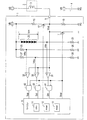
図1に示すように、第1実施形態の電磁装置駆動装置(以下単に、駆動装置という)1は、電磁装置として、例えば電磁弁2を駆動する。電磁弁2は、該電磁弁2のコイル3に電流が流れることで動作する(例えば閉弁状態から開弁状態に変化する)。
[First Embodiment]
As shown in FIG. 1, an electromagnetic device drive device (hereinafter simply referred to as a drive device) 1 of the first embodiment drives, for example, an electromagnetic valve 2 as an electromagnetic device. The electromagnetic valve 2 operates when a current flows through the coil 3 of the electromagnetic valve 2 (for example, the valve is changed from the closed state to the opened state).
この第1実施形態では、バッテリ4の高電位側の電位(即ち、プラス端子の電位であり、以下、バッテリ電圧VBという)が、第1電位に該当し、バッテリ4の低電位側の電位(即ち、マイナス端子の電位であり、以下、グランド電位VGという)が、第2電位に該当する。以下の説明において、各電圧は、グランド電位VGを0Vとした電圧である。 In the first embodiment, the potential on the high potential side of the battery 4 (that is, the potential of the plus terminal, hereinafter referred to as the battery voltage VB) corresponds to the first potential, and the potential on the low potential side of the battery 4 ( That is, the potential of the minus terminal, hereinafter referred to as the ground potential VG) corresponds to the second potential. In the following description, each voltage is a voltage in which the ground potential VG is 0V.
電磁弁2のコイル3の一端は、駆動装置1の外部において、バッテリ電圧VBに接続されており、コイル3の他端は、駆動装置1に備えられた出力端子5に接続されている。
駆動装置1は、出力端子5とグランド電位VGとの間に設けられた通電用スイッチ7と、通電用スイッチ7のオン/オフを制御するマイコン9とを備える。
One end of the coil 3 of the electromagnetic valve 2 is connected to the battery voltage VB outside the drive device 1, and the other end of the coil 3 is connected to the
The drive device 1 includes an
通電用スイッチ7がオンすると、出力端子5とグランド電位VGとの間の電流経路が接続して、コイル3に電流が流れ、通電用スイッチ7がオフすると、その電流経路が遮断されて、コイル3への通電が停止する。つまり、駆動装置1は、ローサイド駆動の駆動装置である。
When the
マイコン9は、通電用スイッチ7の駆動信号Soutをアクティブレベル(この例ではハイ)にすることにより、通電用スイッチ7をオンさせて、コイル3に電流を流す。マイコン9は、CPU11、ROM12及びRAM13等を備えている。マイコン9の動作は、CPU11がROM12内のプログラムを実行することで実現される。
The
また、駆動装置1は、バッテリ電圧VBに一端が接続された抵抗15と、抵抗15の他端と出力端子5との間に設けられた接続切替用スイッチ17と、出力端子5とグランド電位VGとの間に接続された抵抗19と、を備える。
Further, the driving device 1 includes a
接続切替用スイッチ17は、マイコン9によってオン/オフが制御される。接続切替用スイッチ17がオンすれば、出力端子5とバッテリ電圧VBとの間に抵抗15が接続される。また、接続切替用スイッチ17がオフすれば、出力端子5とバッテリ電圧VBとの間への抵抗15の接続が解除される。尚、接続切替用スイッチ17は、バッテリ電圧VBと抵抗15との間に設けられていても良い。
The
更に、駆動装置1は、グランド電位VGに一端が接続された抵抗21と、抵抗21の他端とバッテリ電圧VBとの間に、カソードを抵抗21側にして、直列に接続された複数のダイオード23と、を備える。
Further, the driving device 1 includes a
ダイオード23の1つあたりの順方向電圧を「Vf」とし、ダイオード23の数を「N」とすると、抵抗21とダイオード23との接続点には、「VB−Vf×N」の電圧が、第1の閾値電圧Vthrとして発生する。第1の閾値電圧Vthrは、第1電位としてのバッテリ電圧VBを基準にして、そのバッテリ電圧VBよりも一定電圧Vcn(=Vf×N)だけ低い電圧(即ち、グランド電位VG側の電圧)であり、異常判定用電圧に相当する。尚、図1では、ダイオード23を6個示しているが、その個数は一例であり、このことは、後述する他の構成図についても同様である。
When the forward voltage per one
また、駆動装置1は、バッテリ電圧VBとグランド電位VGとの間に直列に接続された2つの抵抗25,26と、バッテリ電圧VBとグランド電位VGとの間に直列に接続された2つの抵抗27,28と、を備える。
The driving device 1 also includes two
抵抗25の抵抗値をR25とし、抵抗26の抵抗値をR26とすると、抵抗25と抵抗26との接続点には、バッテリ電圧VBを2つの抵抗25,26による一定の比率で分圧した電圧であって、「VB×R26/(R25+R26)」の電圧が、第2の閾値電圧Vthoとして発生する。第2の閾値電圧Vthoは、断線判定用電圧に相当する。
Assuming that the resistance value of the
抵抗27の抵抗値をR27とし、抵抗28の抵抗値をR28とすると、抵抗27と抵抗28との接続点には、バッテリ電圧VBを2つの抵抗27,28による一定の比率で分圧した電圧であって、「VB×R28/(R27+R28)」の電圧が、第3の閾値電圧Vthsとして発生する。第3の閾値電圧Vthsは、完全ショート判定用電圧に相当する。
Assuming that the resistance value of the
そして、駆動装置1は、出力端子5の電圧(以下、端子電圧ともいう)Voutと第1の閾値電圧Vthrとを比較して、端子電圧Voutが第1の閾値電圧Vthrよりも低い電圧であるか否かを判定する比較器31と、端子電圧Voutと第2の閾値電圧Vthoとを比較して、端子電圧Voutが第2の閾値電圧Vthoよりも低い電圧であるか否かを判定する比較器32と、端子電圧Voutと第3の閾値電圧Vthsとを比較して、端子電圧Voutが第3の閾値電圧Vthsよりも低い電圧であるか否かを判定する比較器33と、を備える。
Then, the driving device 1 compares the voltage Vout of the output terminal 5 (hereinafter also referred to as terminal voltage) Vout with the first threshold voltage Vthr, and the terminal voltage Vout is a voltage lower than the first threshold voltage Vthr. A
比較器31の出力信号は、「Vthr>Vout」であればハイになり、「Vthr≦Vout」であればローになる。比較器32の出力信号は、「Vtho>Vout」であればハイになり、「Vtho≦Vout」であればローになる。比較器33の出力信号は、「Vths>Vout」であればハイになり、「Vths≦Vout」であればローになる。
The output signal of the
更に、駆動装置1は、マイコン9から出力される通電用スイッチ7の駆動信号Soutをレベル反転させた信号と、比較器31の出力信号との、論理積信号を出力するアンド回路41と、駆動信号Soutをレベル反転させた信号と、比較器32の出力信号との、論理積信号を出力するアンド回路42と、駆動信号Soutをレベル反転させた信号と、比較器33の出力信号との、論理積信号を出力するアンド回路43と、を備える。
Further, the drive device 1 includes an AND
駆動信号Soutが、通電用スイッチ7をオンさせる方のアクティブレベルである場合、アンド回路41,42,43の各出力信号Srs,Sop,Sstは、全てローになる。また、駆動信号Soutが、通電用スイッチ7をオフさせる方の非アクティブレベル(この例ではロー)である場合、アンド回路41の出力信号Srsは、比較器31の出力信号と同じになり、アンド回路42の出力信号Sopは、比較器32の出力信号と同じになり、アンド回路43の出力信号Sstは、比較器33の出力信号と同じになる。そして、このようなアンド回路41,42,43の各出力信号Srs,Sop,Sstは、マイコン9に入力される。
When the drive signal Sout is at the active level for turning on the energizing
次に、第1〜第3の閾値電圧Vthr,Vtho,Vthsについて、図2を用い説明する。
まず、第1の閾値電圧Vthrは、前述したように、バッテリ電圧VBよりもダイオード23による一定電圧Vcn(=Vf×N)だけ低い電圧である。このため、バッテリ電圧VBが変化しても、バッテリ電圧VBと第1の閾値電圧Vthrとの差は一定である。そして、上記一定電圧Vcnは、電磁弁2の最低動作電圧(即ち、電磁弁2が動作することとなるコイル3の両端電位差の最低値)Vminと同じかそれよりも余裕を見て若干小さい電圧に設定されている。
Next, the first to third threshold voltages Vthr, Vtho, Vths will be described with reference to FIG.
First, as described above, the first threshold voltage Vthr is a voltage lower than the battery voltage VB by a constant voltage Vcn (= Vf × N) generated by the
一方、図2において、点線で示す電圧Vopは、接続切替用スイッチ17がオン状態で且つコイル3が断線している場合の端子電圧Vout(以下、断線時電圧Vopという)である。抵抗15の抵抗値をR15とし、抵抗19の抵抗値をR19とすると、断線時電圧Vopは、バッテリ電圧VBを2つの抵抗15,19で分圧した電圧であって、「VB×R19/(R15+R19)」の電圧となる。尚、接続切替用スイッチ17のオン抵抗は、R15及びR19よりも十分に小さいため、無視することができる。
On the other hand, in FIG. 2, a voltage Vop indicated by a dotted line is a terminal voltage Vout (hereinafter referred to as a disconnection voltage Vop) when the
そして、第2の閾値電圧Vthoは、断線時電圧Vopと同様に、バッテリ電圧VBとグランド電位VGとの間の電圧であるが、断線時電圧Vopよりも少し高い電圧(バッテリ電圧VB側の電圧)に設定されている。つまり、抵抗25,26によるバッテリ電圧VBの分圧比(R26/(R25+R26))は、抵抗15,19によるバッテリ電圧VBの分圧比(R19/(R15+R19)よりも、大きく設定されている。
The second threshold voltage Vtho is a voltage between the battery voltage VB and the ground potential VG, similar to the disconnection voltage Vop, but is slightly higher than the disconnection voltage Vop (voltage on the battery voltage VB side). ) Is set. That is, the voltage dividing ratio (R26 / (R25 + R26)) of the battery voltage VB by the
また、第3の閾値電圧Vthsも、バッテリ電圧VBとグランド電位VGとの間の電圧であるが、断線時電圧Vopよりも低い電圧(グランド電位VG側の電圧)に設定されている。つまり、抵抗27,28によるバッテリ電圧VBの分圧比(R28/(R27+R28))は、抵抗15,19によるバッテリ電圧VBの分圧比(R19/(R15+R19)よりも、小さく設定されている。更に、第3の閾値電圧Vthsは、バッテリ電圧VBが少なくとも正常範囲(例えば8V〜16Vの範囲)である場合には、第1の閾値電圧Vthrよりも低い電圧となる。
The third threshold voltage Vths is also a voltage between the battery voltage VB and the ground potential VG, but is set to a voltage (voltage on the ground potential VG side) lower than the disconnection voltage Vop. That is, the voltage dividing ratio (R28 / (R27 + R28)) of the battery voltage VB by the
そして、R15及びR19は、コイル3の抵抗値と比較して、十分に大きい値(例えば数百倍から数千倍程度)に設定されている。このため、通電用スイッチ7がオフされている期間(以下、電磁弁2の非駆動期間という)において、正常ならば、端子電圧Voutは、第1〜第3の閾値電圧Vthr,Vtho,Vthsよりも高い電圧であって、実質的にバッテリ電圧VB(バッテリ電圧VBとさほど変わらない電圧)になる。
R15 and R19 are set to a sufficiently large value (for example, about several hundred times to several thousand times) as compared with the resistance value of the coil 3. Therefore, if the energizing
よって、電磁弁2の非駆動期間において、正常であれば、「Vthr≦Vout」、「Vtho≦Vout」、「Vths≦Vout」の関係が成立して、比較器31〜33の出力信号が全てローになり、アンド回路41〜43の出力信号Srs,Sop,Sstも全てローになる。
Therefore, if the solenoid valve 2 is normal during the non-drive period, the relations “Vthr ≦ Vout”, “Vtho ≦ Vout”, and “Vths ≦ Vout” are established, and all the output signals of the
一方、電磁弁2の非駆動期間において、出力端子5がグランド電位VGにレアショートし、コイル3の両端電位差が電磁弁2の最低動作電圧Vmin以上になった場合には、「Vthr>Vout」の関係が成立して、比較器31の出力信号がハイになり、アンド回路41の出力信号Srsもハイになる。
On the other hand, when the
よって、アンド回路41の出力信号Srsがハイであることは、出力端子5のグランド電位VGへのレアショートのうち、電磁弁2の不要な動作を招くレアショートである動作誘発レアショートの発生を示すこととなる。つまり、第1の閾値電圧Vthrは、動作誘発レアショートを検出するための閾値電圧であり、上記一定電圧Vcnは、動作誘発レアショートが発生した場合に、比較器31の出力信号がハイになるように設定されている。
Therefore, when the output signal Srs of the AND
このため、例えば、マイコン9は、電磁弁2の非駆動期間において、アンド回路41の出力信号Srsがハイであれば、出力端子5のグランド電位VGへのレアショートが発生していると判定することができ、特に動作誘発レアショートが発生していると判定することができる。
For this reason, for example, if the output signal Srs of the AND
ここで、比較例として、動作誘発レアショートを検出するための閾値電圧を、抵抗によってバッテリ電圧VBを分圧して発生させたとする。しかし、そのように構成すると、バッテリ電圧VBが高い場合ほど、バッテリ電圧VBと閾値電圧との差が大きくなり、その差が一定にならないため、動作誘発レアショートを検出できなかったり、誤検出してしまったりすることとなる。 Here, as a comparative example, it is assumed that a threshold voltage for detecting an operation-induced rare short is generated by dividing the battery voltage VB with a resistor. However, with such a configuration, the higher the battery voltage VB, the greater the difference between the battery voltage VB and the threshold voltage, and the difference is not constant. It will be.
分かりやすくするための便宜上、例えば、図2におけるVthoを、動作誘発レアショートを検出するための閾値電圧とし、「Vtho>Vout」であれば、動作誘発レアショートが発生していると判定する、というように構成したとする。 For the sake of convenience, for example, Vtho in FIG. 2 is set as a threshold voltage for detecting an operation-induced rare short, and if “Vtho> Vout”, it is determined that an operation-induced rare short has occurred. It is assumed that it is configured as follows.
しかし、その構成では、バッテリ電圧VBが高い場合に、図2において「Vthrより低いが、Vthoよりは高い」範囲が発生する。このため、動作誘発レアショートが発生して、端子電圧Voutが、その「Vthrより低いが、Vthoよりは高い」範囲に入った場合には、動作誘発レアショートの発生を異常として検出することができない。また逆に、バッテリ電圧VBが低い場合には、図2において「Vthrより高いが、Vthoよりも低い」範囲が発生する。このため、端子電圧Voutが、その「Vthrより高いが、Vthoよりも低い」範囲に入った場合には、動作誘発レアショートが発生していないのに、動作誘発レアショートが発生していると誤判定してしまうこととなる。 However, in the configuration, when the battery voltage VB is high, a range “lower than Vthr but higher than Vtho” in FIG. 2 occurs. For this reason, when an operation-induced rare short occurs and the terminal voltage Vout enters the range of “lower than Vthr but higher than Vtho”, the occurrence of the operation-induced rare short may be detected as abnormal. Can not. Conversely, when the battery voltage VB is low, a range “higher than Vthr but lower than Vtho” in FIG. 2 occurs. For this reason, when the terminal voltage Vout is in the range of “higher than Vthr but lower than Vtho”, an operation-induced rare short has not occurred, but an operation-induced rare short has occurred. It will be misjudged.
これに対して、本実施形態では、動作誘発レアショートを検出するための第1の閾値電圧Vthrとして、バッテリ電圧VBよりも一定電圧Vcnだけ低い電圧を用いているため、バッテリ電圧VBが変化しても、動作誘発レアショートを正しく検出することができるようになる。 On the other hand, in the present embodiment, since the voltage that is lower than the battery voltage VB by the constant voltage Vcn is used as the first threshold voltage Vthr for detecting the operation induced rare short circuit, the battery voltage VB changes. However, the motion-induced rare short can be correctly detected.
また、電磁弁2の非駆動期間において、接続切替用スイッチ17がオンしており、コイル3が断線している場合には、端子電圧Voutが断線時電圧Vopになるため、「Vtho>Vout」の関係が成立して、比較器32の出力信号がハイになり、アンド回路42の出力信号Sopもハイになる。また、コイル3の上流側をバッテリ電圧VBに接続する配線と、コイル3の下流側を出力端子5に接続する配線との、何れかが断線した場合にも、コイル3が断線した場合と同じ状態になる。よって、アンド回路42の出力信号Sopがハイであることは、バッテリ電圧VBからコイル3を経由して出力端子5に至る電流経路が断線した異常(以下、断線故障という)の発生を示すこととなる。つまり、第2の閾値電圧Vthoは、断線故障を検出するための閾値電圧である。
Further, when the
また、電磁弁2の非駆動期間において、出力端子5がグランド電位VGに完全にショートした異常である完全ショートが発生した場合には、「Vths>Vout」の関係が成立して、比較器33の出力信号がハイになり、アンド回路43の出力信号Sstもハイになる。よって、アンド回路43の出力信号Sstがハイであることは、完全ショートの発生を示すこととなる。つまり、第3の閾値電圧Vthsは、基本的には完全ショートを検出するための閾値電圧である。
Further, in the non-driving period of the solenoid valve 2, when a complete short circuit, which is an abnormality in which the
以上のことから、マイコン9は、電磁弁2の非駆動期間において、アンド回路41,42,43の出力信号Srs,Sop,Sstにより、動作誘発レアショートと、断線故障と、完全ショートとの、何れかの異常が発生していることを検出することができる。
From the above, during the non-drive period of the solenoid valve 2, the
また、動作誘発レアショート又は完全ショート(以下、これらを総称する場合には「ショート」という)が発生した場合には、電磁弁2が動作したままになってしまうのに対し、断線故障が発生した場合には、電磁弁2を動作させることができなくなってしまう。このため、ショートが発生した場合と、断線故障が発生した場合とでは、実施すべきフェールセーフが異なる。よって、ショートと断線故障とを区別して検出することが好ましい。尚、出力端子5のグランド電位VGへのショートは、例えば、通電用スイッチ7が故障して、該通電用スイッチ7の2つの出力端子(この例ではドレインとソース)がショートすることによっても、起こる現象である。
In addition, when an operation-induced rare short or complete short (hereinafter referred to as “short” when collectively referred to) occurs, the electromagnetic valve 2 remains in operation, but a disconnection failure occurs. In such a case, the solenoid valve 2 cannot be operated. For this reason, the fail-safe to be implemented differs between when a short circuit occurs and when a disconnection failure occurs. Therefore, it is preferable to detect the short circuit and the disconnection failure separately. Note that the short-circuit of the
ここで、図2に示す閾値電圧Vthr,Vtho,Vthsの関係から、マイコン9は、アンド回路43の出力信号Sstがハイであれば、他のアンド回路41,42の出力信号Srs,Sopに拘わらず、完全ショートが発生していると判定することができる。また、マイコン9は、アンド回路41〜43の出力信号Srs,Sop,Sstのうち、出力信号Srsだけがハイであれば、動作誘発レアショートが発生していると判定することができ、出力信号Sopだけがハイであれば、断線故障が発生していると判定することができる。
Here, from the relationship between the threshold voltages Vthr, Vth0, and Vths shown in FIG. 2, if the output signal Sst of the AND
一方、図2における斜線部で示すように、本実施形態では、端子電圧Voutの領域として、第3の閾値電圧Vthsより高いが、第1の閾値電圧Vthrと第2の閾値電圧Vthoとの両方よりも低い、という領域が存在する。このことは、アンド回路43の出力信号Sstがローで、アンド回路41,42の出力信号Srs,Sopが両方ともハイになる場合がある、ということを意味している。このため、出力信号Srs,Sopのレベルの組み合わせだけでは、動作誘発レアショートと断線故障とを区別して検出することができない。
On the other hand, as shown by the hatched portion in FIG. 2, in the present embodiment, the region of the terminal voltage Vout is higher than the third threshold voltage Vths, but both the first threshold voltage Vthr and the second threshold voltage Vtho are both. There is an area that is lower. This means that the output signal Sst of the AND
そこで、マイコン9は、図3の診断処理により、動作誘発レアショートと断線故障と完全ショートとを、区別して検出する。尚、マイコン9は、図3の診断処理を、例えば一定時間毎に実行する。
Therefore, the
図3に示すように、マイコン9は、診断処理を開始すると、まずS110にて、電磁弁2の非駆動期間であるか否かを判定する。具体的には、駆動信号Soutをローにしているか否かを判定する。
As shown in FIG. 3, when starting the diagnostic process, the
マイコン9は、S110にて、非駆動期間ではないと判定した場合(即ち、駆動信号Soutをハイにしている場合)には、そのまま当該診断処理を終了する。
また、マイコン9は、S110にて、非駆動期間であると判定した場合(即ち、駆動信号Soutをローにしている場合)には、S120に進み、接続切替用スイッチ17をオンさせる。尚、接続切替用スイッチ17は、診断処理を開始する前からオンさせておいても良く、例えば、通電用スイッチ7をオンさせている期間中に、接続切替用スイッチ17をオンさせておくようにしても良い。
If the
If the
次に、マイコン9は、S130にて、アンド回路43の出力信号Sstがハイであるか否かを判定し、出力信号Sstがハイであれば、S140に進んで、完全ショートが発生していると判定し、その後、当該診断処理を終了する。尚、S140の具体的な処理としては、例えば、完全ショートが発生していることを示すフラグをセットする。
Next, in S130, the
また、マイコン9は、S130にて、出力信号Sstがハイではない(ローである)と判定した場合には、S150に移行して、アンド回路41の出力信号Srsがハイであるか否かを判定する。マイコン9は、S150にて、出力信号Srsがハイであると判定した場合には、S170に進む。
If the
また、マイコン9は、S150にて、出力信号Srsがハイではない(ローである)と判定した場合には、S160に移行して、アンド回路42の出力信号Sopがハイであるか否かを判定する。マイコン9は、S160にて、出力信号Sopがハイではない(ローである)と判定した場合には、そのまま当該診断処理を終了するが、出力信号Sopがハイであると判定した場合には、S170に進む。
If the
つまり、マイコン9は、出力信号Srsと出力信号Sopとの少なくも一方がハイである場合には、動作誘発レアショートと断線故障との何れかが発生していると判定して、S170に進む。
That is, when at least one of the output signal Srs and the output signal Sop is high, the
そして、マイコン9は、S170では、動作誘発レアショートと断線故障とを判別するために、接続切替用スイッチ17をオンからオフさせる。
断線故障が発生していれば、接続切替用スイッチ17がオフされると、端子電圧Voutは、抵抗19の作用により、グランド電位VG(<Vths)になるため、アンド回路43の出力信号Sstがハイになる。また、動作誘発レアショートが発生している場合には、接続切替用スイッチ17がオフされても、端子電圧Voutは変化せず、S130でアンド回路43の出力信号Sstがローと判定された時点の電圧と同じ電圧(即ち、第3の閾値電圧Vths以上の電圧)になる。よって、アンド回路43の出力信号Sstはローになる。
In S170, the
If a disconnection failure has occurred, when the
このため、マイコン9は、次のS180にて、アンド回路43の出力信号Sstがハイであるか否かを判定し、出力信号Sstがハイであれば、S190に進んで、断線故障が発生していると判定する。尚、S190の具体的な処理としては、例えば、断線故障が発生していることを示すフラグをセットする。そして、マイコン9は、その後、当該診断処理を終了する。
For this reason, the
また、マイコン9は、S180にて、出力信号Sstがハイではない(ローである)と判定した場合には、S200に移行して、動作誘発レアショートが発生していると判定する。尚、S200の具体的な処理としては、例えば、動作誘発レアショートが発生していることを示すフラグをセットする。そして、マイコン9は、その後、当該診断処理を終了する。
If the
つまり、マイコン9は、診断処理では、電磁弁2の非駆動期間において、接続切替用スイッチ17をオンさせた状態で、比較器33により、端子電圧Voutが第3の閾値電圧Vthsよりも低い電圧であると判定された場合には(S130:YES)、完全ショートが発生していると判定している(S140)。
That is, in the diagnosis process, the
また、マイコン9は、診断処理では、電磁弁2の非駆動期間において、接続切替用スイッチ17をオンさせた状態で、比較器33により、端子電圧Voutが第3の閾値電圧Vthsよりも低い電圧ではないと判定された場合に(S130:NO)、比較器31により、端子電圧Voutが第1の閾値電圧Vthrよりも低い電圧であると判定された場合(S150:YES)、あるいは、比較器32により、端子電圧Voutが第2の閾値電圧Vthoよりも低い電圧であると判定された場合には(S160:YES)、異常が発生していると判定するが(S190又はS200)、その発生している異常を判別するために接続切替用スイッチ17をオンからオフさせる(S170)。そして、マイコン9は、その後、比較器33により、端子電圧Voutが第3の閾値電圧Vthsよりも低い電圧であると判定された場合には(S180:YES)、断線故障が発生していると判定し(S190)、比較器33により、端子電圧Voutが第3の閾値電圧Vthsよりも低い電圧ではないと判定された場合には(S180:NO)、出力端子5のグランド電位VGへのレアショート(特に動作誘発レアショート)が発生していると判定している(S200)。
In the diagnosis process, the
ここで、診断処理が行われることによる駆動装置1の作用を、図4〜図6を用い説明する。
図4に示すように、駆動信号Soutがローになっている非駆動期間において、時刻t1で完全ショート(出力端子5のグランドショート)が発生したとすると、アンド回路41,42,43の出力信号Srs,Sop,Sstが全てハイになる。そして、出力信号Sstがハイになることで、マイコン9は、完全ショートが発生したと判定する(S130:YES→S140)。
Here, the effect | action of the drive device 1 by performing a diagnostic process is demonstrated using FIGS.
As shown in FIG. 4, if a complete short circuit (ground short of the output terminal 5) occurs at time t1 in the non-drive period in which the drive signal Sout is low, the output signals of the AND
図5に示すように、駆動信号Soutがローになっている非駆動期間において、時刻t2で断線故障が発生したとすると、その場合、アンド回路43の出力信号Sstはローになるが、アンド回路42の出力信号Sopはハイになる。また、アンド回路41の出力信号Srsもハイになる可能性がある。図5の例ではSopとSrsとの両方がハイになった場合を例示している。その場合、マイコン9は、接続切替用スイッチ17をオンからオフさせる。すると、端子電圧Voutは、断線時電圧Vopからグランド電位VG(=0V)になるため、アンド回路43の出力信号Sstがハイになり、その結果、マイコン9は、断線故障が発生したと判定する(S180:YES→S190)。
As shown in FIG. 5, if a disconnection failure occurs at time t2 in the non-driving period in which the drive signal Sout is low, in this case, the output signal Sst of the AND
図6に示すように、駆動信号Soutがローになっている非駆動期間において、時刻t3で動作誘発レアショートが発生したとすると、その場合、アンド回路43の出力信号Sstはローになるが、アンド回路41の出力信号Srsはハイになる。また、アンド回路42の出力信号Sopもハイになる可能性がある。図6の例ではSrsとSopとの両方がハイになった場合を例示している。その場合、マイコン9は、接続切替用スイッチ17をオンからオフさせる。しかし、動作誘発レアショートの発生時において、端子電圧Voutは、接続切替用スイッチ17のオン/オフによって変化しないため、アンド回路43の出力信号Sstはローのままになる。よって、マイコン9は、動作誘発レアショートが発生したと判定する(S180:NO→S200)。
As shown in FIG. 6, in the non-driving period in which the drive signal Sout is low, if an operation-induced rare short occurs at time t3, in that case, the output signal Sst of the AND
第1実施形態の駆動装置1では、以上のような診断処理が行われることにより、動作誘発レアショートと断線故障と完全ショートとを、区別して検出することができる。また、コイル3に流れる電流を検出するための手段も不要である。そして、マイコン9は、動作誘発レアショート又は完全ショートの発生を検出した場合には、例えば、電磁弁2の不要な動作を強制的に停止させるための処理や、電磁弁2が動作することによる影響を抑制するための処理を、フェールセーフ処理として行う。また、マイコン9は、断線故障の発生を検出した場合には、例えば、電磁弁2が動作しないことによる影響を抑制するための処理を、フェールセーフ処理として行う。
In the driving device 1 of the first embodiment, the operation-induced rare short, the disconnection failure, and the complete short can be distinguished and detected by performing the above-described diagnostic processing. Further, no means for detecting the current flowing through the coil 3 is required. When the
[第2実施形態]
次に、第2実施形態の駆動装置について説明する。尚、第1実施形態と同様の構成要素や処理については、第1実施形態と同じ符号を用いるため、詳細な説明は省略する。そして、このことは、後述する他の実施形態についても同様である。
[Second Embodiment]
Next, the drive device of 2nd Embodiment is demonstrated. In addition, about the component and process similar to 1st Embodiment, since the same code | symbol as 1st Embodiment is used, detailed description is abbreviate | omitted. This also applies to other embodiments described later.
図7に示す第2実施形態の駆動装置51は、第1実施形態の駆動装置1と比較すると、下記〈1〉,〈2〉の点が異なっている。
〈1〉抵抗15、接続切替用スイッチ17、抵抗25〜28、比較器32,33及びアンド回路42,43が削除されている。
The
<1> The
〈2〉マイコン9は、図3の診断処理に代えて、図8の診断処理を実行する。
図8の診断処理は、図3の診断処理と比較すると、S120〜S140,S160〜S200が削除されていると共に、S170〜S200に代えて、S210が設けられている。
<2> The
Compared with the diagnostic process of FIG. 3, the diagnostic process of FIG. 8 has S120 to S140 and S160 to S200 deleted, and S210 is provided instead of S170 to S200.
そして、マイコン9は、図8の診断処理では、S110にて、非駆動期間であると判定した場合に、S150に進み、アンド回路41の出力信号Srsがハイではないと判定した場合には、そのまま当該診断処理を終了するが、出力信号Srsがハイであると判定した場合には、S210に進む。マイコン9は、そのS210にて、異常が発生していると判定する。つまり、マイコン9は、電磁弁2の非駆動期間において、比較器31により端子電圧Voutが第1の閾値電圧Vthrよりも低い電圧である(「Vthr>Vout」)と判定された場合に、異常が発生していると判定する。尚、S210の具体的な処理としては、例えば、異常が発生していることを示すフラグをセットする。そして、マイコン9は、その後、当該診断処理を終了する。
Then, in the diagnosis processing of FIG. 8, when the
このような駆動装置51では、電磁弁2の非駆動期間において、動作誘発レアショートが発生している場合には、第1実施形態と同様に、比較器31の出力信号及びアンド回路41の出力信号Srsがハイになる。そして、アンド回路41の出力信号Srsがハイになると、マイコン9は、異常が発生していると判定する。よって、この駆動装置51によっても、動作誘発レアショートが発生した場合には、バッテリ電圧VBに拘わらず、その動作誘発レアショートを異常として検出することができる。
In such a
尚、駆動装置51では、電磁弁2の非駆動期間において、断線故障と完全ショートとの何れが発生している場合には、端子電圧Voutがグランド電位VGになるため、やはり、アンド回路41の出力信号Srsがハイになる。このため、マイコン9は、断線故障と完全ショートも、異常として検出することとなる。よって、この駆動装置51は、動作誘発レアショートと断線故障と完全ショートとを、区別して検出する必要がない場合に、構成が簡単という点で有効である。
In the driving
[第3実施形態]
次に、第3実施形態の駆動装置について説明する。
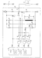
図9に示す第3実施形態の駆動装置53は、第1実施形態の駆動装置1と比較すると、下記《1》〜《3》の点が異なっている。
[Third Embodiment]
Next, the drive device of 3rd Embodiment is demonstrated.
The driving
《1》第1実施形態の駆動装置1がローサイド駆動の駆動装置であったのに対して、第3実施形態の駆動装置53は、ハイサイド駆動の駆動装置である。このため、第3実施形態では、グランド電位VGが第1電位に該当し、バッテリ電圧VBが第2電位に該当しており、駆動装置53の構成は、第1実施形態の駆動装置1における「バッテリ電圧VB」と「グランド電位VG」とを、逆にした構成になっている。
<< 1 >> The drive device 1 of the first embodiment is a low-side drive device, whereas the
《2》上記《1》のことにより、図10に示すように、第1の閾値電圧Vthrは、グランド電位VGよりも一定電圧Vcnだけ高い電圧である。そして、第1の閾値電圧Vthrと、第2の閾値電圧Vthoと、断線時電圧Vopと、第3の閾値電圧Vthsとの、大小関係は、第1実施形態での大小関係(図2)と逆になっている。 << 2 >> Due to the above << 1 >>, as shown in FIG. 10, the first threshold voltage Vthr is a voltage higher than the ground potential VG by a constant voltage Vcn. The magnitude relationship among the first threshold voltage Vthr, the second threshold voltage Vtho, the disconnection time voltage Vop, and the third threshold voltage Vths is the magnitude relationship in the first embodiment (FIG. 2). It is reversed.
《3》更に、上記《1》,《2》のことにより、比較器31の出力信号は、「Vthr<Vout」であればハイになり、「Vthr≧Vout」であればローになる。同様に、比較器32の出力信号は、「Vtho<Vout」であればハイになり、「Vtho≧Vout」であればローになる。同様に、比較器33の出力信号は、「Vths<Vout」であればハイになり、「Vths≧Vout」であればローになる。
<< 3 >> Further, because of the above << 1 >> and << 2 >>, the output signal of the
第3実施形態の駆動装置53では、駆動形態がハイサイド駆動であるため、電磁弁2を不要に動作させてしまうという故障モードの観点で考慮すべき出力端子5のショート先は、バッテリ電圧VBということになる。このため、動作誘発レアショートは、出力端子5のバッテリ電圧VBへのレアショートのうち、電磁弁2の不要な動作を招くレアショートであり、完全ショートは、出力端子5がバッテリ電圧VBに完全にショートした異常である。一方、断線故障は、グランド電位VGからコイル3を経由して出力端子5に至る電流経路が断線した異常である。そして、マイコン9は、図3と同じ診断処理を実行する。
In the driving
尚、駆動装置53において、通電用スイッチ7は、図示しない駆動回路により、マイコン9からの駆動信号Soutに応じてオン/オフさせる。接続切替用スイッチ17も、図示しない駆動回路により、マイコン9からの駆動信号に応じてオン/オフされる。また、第1実施形態の駆動装置1においても、そのような駆動回路が設けられていても良い。
In the driving
そして、以上のような駆動装置53によっても、第1実施形態の駆動装置1と同じ効果が得られる。
以上、本発明の一実施形態について説明したが、本発明は、上記実施形態に限定されず、特許請求の範囲に記載された本発明の要旨の範囲において、種々の態様で実施することができ、前述した実施形態の構成や処理のうちの、何れかの組み合わせを変える変形や、一部を削除する変形等を行うことも可能である。また、前述した数値も一例である。
The same effect as that of the driving device 1 of the first embodiment can be obtained by the driving
As mentioned above, although one Embodiment of this invention was described, this invention is not limited to the said embodiment, In the range of the summary of this invention described in the claim, it can implement in a various aspect. It is also possible to perform a modification that changes any combination of the configurations and processes of the above-described embodiment, a modification that deletes a part, and the like. Moreover, the numerical value mentioned above is also an example.
例えば、抵抗25〜28に代えて、バッテリ電圧VBとグランド電位VGとの間に3つの抵抗を直列に接続し、その3つの抵抗同士の2つの接続点に生じる各電圧を、第2の閾値電圧Vthoと第3の閾値電圧Vthsとの、各々とするように構成しても良い。
For example, instead of the
また、アンド回路41〜43を削除して、比較器31〜33の出力信号を、マイコン9に入力させる構成を採ることもできる。
また、第1の閾値電圧Vthrを発生させるためには、ダイオード23の代わりに、ツェナーダイオードを用いても良い。その場合、一定電圧Vcnと同じツェナー電圧を有するツェナーダイオードを、ダイオード23の向きとは逆向きに設ければ、1つのツェナーダイオードで所望の閾値電圧Vthrを発生させることができる。
Further, the AND
In order to generate the first threshold voltage Vthr, a Zener diode may be used instead of the
また、第3実施形態の駆動装置53を変形して、第2実施形態の駆動装置51と同様の構成にしても良い。また、駆動対象の電磁装置は、ソレノイドや直流モータ等でも良い。また、電源は、車載バッテリ以外でも良い。
Further, the
1,51,53…電磁装置駆動装置、2…電磁弁(電磁装置)、3…コイル、4…バッテリ(電源)、5…出力端子、7…通電用スイッチ、9…マイコン、21…抵抗、23…ダイオード、31…比較器
DESCRIPTION OF
Claims (5)
前記電源の高電位側と低電位側とのうちで前記第1電位とは異なる方である第2電位と前記出力端子との間の電流経路を、オンすることで接続し、オフすることで、前記電流経路を遮断する通電用スイッチ(7)と、
前記通電用スイッチをオンさせることにより、前記コイルに電流を流す制御手段(9)と、
を備えた電磁装置駆動装置(1,51,53)に用いられる異常検出装置であって、
前記第1電位を基準にして、該第1電位よりも所定の一定電圧だけ前記第2電位側の電圧を、異常判定用電圧として発生する異常判定用電圧発生手段(21,23)と、
前記出力端子の電圧が前記異常判定用電圧よりも前記第2電位側の電圧であるか否かを判定する電圧判定手段(31)と、
前記通電用スイッチがオフされている期間において、前記電圧判定手段により、前記出力端子の電圧が前記異常判定用電圧よりも前記第2電位側の電圧であると判定された場合に、異常が発生していると判定する異常判定手段(9,S110〜S200,S210)と、
を備えることを特徴とする電磁装置駆動装置の異常検出装置。 An electromagnetic device that operates when one end of the coil (3) is connected to a first potential that is one of a high potential side and a low potential side of a power source (4) that can change an output voltage, and a current flows through the coil. (2), an output terminal (5) connected to the other end of the coil;
By turning on and turning off a current path between a second potential, which is different from the first potential, between the high potential side and the low potential side of the power source and the output terminal, An energization switch (7) for interrupting the current path;
A control means (9) for causing a current to flow through the coil by turning on the energization switch;
An abnormality detecting device used for an electromagnetic device driving device (1, 51, 53) comprising:
An abnormality determination voltage generating means (21, 23) for generating, as an abnormality determination voltage, a voltage on the second potential side by a predetermined constant voltage with respect to the first potential;
Voltage determination means (31) for determining whether or not the voltage of the output terminal is a voltage on the second potential side of the abnormality determination voltage;
An abnormality occurs when the voltage determination unit determines that the voltage at the output terminal is a voltage on the second potential side of the abnormality determination voltage during a period when the energization switch is off. Abnormality determining means (9, S110 to S200, S210) for determining that the
An abnormality detection device for an electromagnetic device driving device comprising:
前記異常判定手段(9,S110,S150,S200)は、
前記異常として、前記出力端子が所定のインピーダンスを持った状態で前記第2電位にショートした異常であるレアショートが、発生していると判定すること、
を特徴とする電磁装置駆動装置の異常検出装置。 In the abnormality detection apparatus of the electromagnetic device drive device according to claim 1,
The abnormality determination means (9, S110, S150, S200)
Determining that a rare short, which is an abnormality shorted to the second potential in a state where the output terminal has a predetermined impedance, has occurred as the abnormality;
An abnormality detection device for an electromagnetic device driving device.
オンすることで、前記出力端子と前記第1電位との間に第1抵抗(15)を接続させ、オフすることで、前記出力端子と前記第1電位との間に前記第1抵抗が接続されるのを解除する接続切替用スイッチ(17)と、
前記出力端子と前記第2電位との間に接続された第2抵抗(19)と、
前記第1電位と前記第2電位との電位差を一定の比率で分圧することにより、前記第1電位と前記第2電位との間の電圧であると共に、前記接続切替用スイッチがオン状態で且つ前記コイルが断線している場合の前記出力端子の電圧である断線時電圧よりも前記第1電位側の電圧である断線判定用電圧を発生する断線判定用電圧発生手段(25,26)と、
前記第1電位と前記第2電位との電位差を一定の比率で分圧することにより、前記第1電位と前記第2電位との間の電圧であると共に、前記断線時電圧よりも前記第2電位側の電圧であり、且つ、前記電位差が少なくとも所定の正常範囲である場合には前記異常判定用電圧よりも前記第2電位側の電圧となる完全ショート判定用電圧を発生する完全ショート判定用電圧発生手段(27,28)と、
前記出力端子の電圧が前記完全ショート判定用電圧よりも前記第2電位側の電圧であるか否かを判定する第1の追加判定手段(33)と、
前記出力端子の電圧が前記断線判定用電圧よりも前記第2電位側の電圧であるか否かを判定する第2の追加判定手段(32)と、を備え、
前記異常判定手段(9,S110〜S200)は、
前記通電用スイッチがオフされている期間において、前記接続切替用スイッチをオンさせた状態で、前記第1の追加判定手段により、前記出力端子の電圧が前記完全ショート判定用電圧よりも前記第2電位側の電圧であると判定された場合には、前記出力端子が前記第2電位に完全にショートした異常である完全ショートが発生していると判定し、
前記通電用スイッチがオフされている期間において、前記接続切替用スイッチをオンさせた状態で、前記第1の追加判定手段により、前記出力端子の電圧が前記完全ショート判定用電圧よりも前記第2電位側の電圧ではないと判定された場合に、前記電圧判定手段により、前記出力端子の電圧が前記異常判定用電圧よりも前記第2電位側の電圧であると判定された場合、あるいは、前記第2の追加判定手段により、前記出力端子の電圧が前記断線判定用電圧よりも前記第2電位側の電圧であると判定された場合には、発生している異常を判別するために前記接続切替用スイッチをオンからオフさせ、その後、前記第1の追加判定手段により、前記出力端子の電圧が前記完全ショート判定用電圧よりも前記第2電位側の電圧であると判定された場合には、前記第1電位から前記コイルを経由して前記出力端子に至る電流経路が断線した異常である断線故障が発生していると判定し、前記第1の追加判定手段により、前記出力端子の電圧が前記完全ショート判定用電圧よりも前記第2電位側の電圧ではないと判定された場合には、前記出力端子が所定のインピーダンスを持った状態で前記第2電位にショートした異常であるレアショートが発生していると判定すること、
を特徴とする電磁装置駆動装置の異常検出装置。 In the abnormality detection device for an electromagnetic device driving device according to claim 1 or 2,
By turning on, the first resistor (15) is connected between the output terminal and the first potential, and when turned off, the first resistor is connected between the output terminal and the first potential. A connection switching switch (17) for releasing the connection,
A second resistor (19) connected between the output terminal and the second potential;
By dividing the potential difference between the first potential and the second potential at a constant ratio, the voltage is between the first potential and the second potential, and the connection switching switch is in the ON state and Disconnection determination voltage generating means (25, 26) for generating a disconnection determination voltage that is a voltage on the first potential side of a voltage at the time of disconnection that is a voltage of the output terminal when the coil is disconnected;
By dividing the potential difference between the first potential and the second potential at a constant ratio, the voltage is between the first potential and the second potential, and the second potential is higher than the disconnection voltage. And a complete short determination voltage that generates a complete short determination voltage that is a voltage on the second potential side of the abnormality determination voltage when the potential difference is at least a predetermined normal range. Generating means (27, 28);
First additional determination means (33) for determining whether or not the voltage of the output terminal is a voltage on the second potential side with respect to the complete short-circuit determination voltage;
Second addition determining means (32) for determining whether or not the voltage of the output terminal is a voltage on the second potential side with respect to the disconnection determining voltage;
The abnormality determination means (9, S110 to S200)
In a period in which the energization switch is turned off, the voltage at the output terminal is set to be higher than the complete short-circuit determination voltage by the first additional determination unit while the connection switch is turned on. If it is determined that the voltage is on the potential side, it is determined that a complete short circuit, which is an abnormality in which the output terminal is completely shorted to the second potential, has occurred,
In a period in which the energization switch is turned off, the voltage at the output terminal is set to be higher than the complete short-circuit determination voltage by the first additional determination unit while the connection switch is turned on. When it is determined that the voltage is not a potential side voltage, when the voltage determination unit determines that the voltage at the output terminal is a voltage on the second potential side with respect to the abnormality determination voltage, or When it is determined by the second additional determination means that the voltage at the output terminal is a voltage on the second potential side with respect to the disconnection determination voltage, the connection is performed in order to determine the abnormality that has occurred. The switch for switching is turned off from on, and then the first additional determination means determines that the voltage at the output terminal is a voltage on the second potential side with respect to the complete short-circuit determination voltage. In this case, it is determined that a disconnection failure that is an abnormality in which a current path from the first potential to the output terminal via the coil is disconnected, and the first additional determination unit causes the output to be If it is determined that the voltage at the terminal is not the voltage on the second potential side of the complete short-circuit determination voltage, the output terminal is short-circuited to the second potential with a predetermined impedance. Determining that a rare short has occurred,
An abnormality detection device for an electromagnetic device driving device.
前記第1電位は、前記電源の高電位側の電位であり、前記第2電位は、前記電源の低電位側の電位であること、
を特徴とする電磁装置駆動装置の異常検出装置。 In the abnormality detection apparatus of the electromagnetic device drive device according to any one of claims 1 to 3,
The first potential is a potential on the high potential side of the power source, and the second potential is a potential on the low potential side of the power source;
An abnormality detection device for an electromagnetic device driving device.
前記第1電位は、前記電源の低電位側の電位であり、前記第2電位は、前記電源の高電位側の電位であること、
を特徴とする電磁装置駆動装置の異常検出装置。 In the abnormality detection apparatus of the electromagnetic device drive device according to any one of claims 1 to 3,
The first potential is a potential on the low potential side of the power source, and the second potential is a potential on the high potential side of the power source;
An abnormality detection device for an electromagnetic device driving device.
Priority Applications (1)
| Application Number | Priority Date | Filing Date | Title |
|---|---|---|---|
| JP2013121891A JP2014239380A (en) | 2013-06-10 | 2013-06-10 | Abnormality detection device for electromagnetic device drive device |
Applications Claiming Priority (1)
| Application Number | Priority Date | Filing Date | Title |
|---|---|---|---|
| JP2013121891A JP2014239380A (en) | 2013-06-10 | 2013-06-10 | Abnormality detection device for electromagnetic device drive device |
Publications (1)
| Publication Number | Publication Date |
|---|---|
| JP2014239380A true JP2014239380A (en) | 2014-12-18 |
Family
ID=52136204
Family Applications (1)
| Application Number | Title | Priority Date | Filing Date |
|---|---|---|---|
| JP2013121891A Pending JP2014239380A (en) | 2013-06-10 | 2013-06-10 | Abnormality detection device for electromagnetic device drive device |
Country Status (1)
| Country | Link |
|---|---|
| JP (1) | JP2014239380A (en) |
Cited By (4)
| Publication number | Priority date | Publication date | Assignee | Title |
|---|---|---|---|---|
| JP2016134832A (en) * | 2015-01-21 | 2016-07-25 | 株式会社デンソー | Load drive circuit |
| JP2017002857A (en) * | 2015-06-12 | 2017-01-05 | 株式会社デンソー | Injection valve drive device |
| JP2017225045A (en) * | 2016-06-16 | 2017-12-21 | 株式会社オートネットワーク技術研究所 | Power supply control device |
| CN114320634A (en) * | 2020-09-30 | 2022-04-12 | 日立安斯泰莫株式会社 | Solenoid valve driving device |
-
2013
- 2013-06-10 JP JP2013121891A patent/JP2014239380A/en active Pending
Cited By (7)
| Publication number | Priority date | Publication date | Assignee | Title |
|---|---|---|---|---|
| JP2016134832A (en) * | 2015-01-21 | 2016-07-25 | 株式会社デンソー | Load drive circuit |
| JP2017002857A (en) * | 2015-06-12 | 2017-01-05 | 株式会社デンソー | Injection valve drive device |
| JP2017225045A (en) * | 2016-06-16 | 2017-12-21 | 株式会社オートネットワーク技術研究所 | Power supply control device |
| WO2017217289A1 (en) * | 2016-06-16 | 2017-12-21 | 株式会社オートネットワーク技術研究所 | Power supply control device |
| US10601418B2 (en) | 2016-06-16 | 2020-03-24 | Autonetworks Technologies, Ltd. | Power supply control device |
| CN114320634A (en) * | 2020-09-30 | 2022-04-12 | 日立安斯泰莫株式会社 | Solenoid valve driving device |
| CN114320634B (en) * | 2020-09-30 | 2024-02-20 | 日立安斯泰莫株式会社 | Electromagnetic valve driving device |
Similar Documents
| Publication | Publication Date | Title |
|---|---|---|
| JP6353648B2 (en) | Semiconductor abnormality detection circuit | |
| JP6260552B2 (en) | Power supply | |
| EP2887546B1 (en) | Monitoring method and device for power semiconductor switch | |
| US7548070B2 (en) | Method and circuit arrangement for detecting a wire break | |
| JP2015121418A (en) | Abnormality detection device for electric load driving apparatus | |
| KR101949509B1 (en) | An Apparatus and A Method For Testing A Motor Driving IC | |
| JP2014239380A (en) | Abnormality detection device for electromagnetic device drive device | |
| US9419523B2 (en) | Method for identifying a short-line fault or a line interruption for a switched inductive load | |
| EP3059598B1 (en) | Electrical load controller with fault detection | |
| JP4736569B2 (en) | Inductive load abnormality detection device | |
| CN102739141A (en) | Motor driving device | |
| CN104950238A (en) | Fault detection method and fault detection device for current converter and IGBT drive circuit thereof | |
| JP2014202625A (en) | Failure detection circuit of switch element | |
| JP2013195291A (en) | Voltage change detecting circuit and voltage change detecting method | |
| JP2019017128A (en) | State detection circuit of reverse connection protection device | |
| JP2014224795A (en) | Electric load drive device | |
| JP2011169681A (en) | Apparatus for testing semiconductor device | |
| US11115016B2 (en) | Electronic circuit with two voltage supply circuits | |
| JP4155075B2 (en) | Disconnection detection circuit | |
| JP6655574B2 (en) | Load drive | |
| WO2015092522A1 (en) | Drive control apparatus for semiconductor device | |
| CN113125931B (en) | Circuit abnormality diagnosis device, circuit abnormality diagnosis method, and computer-readable medium | |
| WO2022239622A1 (en) | Ground fault detection device | |
| US11619919B2 (en) | Circuit arrangement for switching an electrical load and method for checking a status of a safety output of a circuit arrangement | |
| JP2010146841A (en) | Failure diagnostic device and failure diagnosis method |