JP2014173792A - Heating water heater - Google Patents
Heating water heater Download PDFInfo
- Publication number
- JP2014173792A JP2014173792A JP2013047147A JP2013047147A JP2014173792A JP 2014173792 A JP2014173792 A JP 2014173792A JP 2013047147 A JP2013047147 A JP 2013047147A JP 2013047147 A JP2013047147 A JP 2013047147A JP 2014173792 A JP2014173792 A JP 2014173792A
- Authority
- JP
- Japan
- Prior art keywords
- hot water
- heating
- water supply
- heat exchanger
- heat
- Prior art date
- Legal status (The legal status is an assumption and is not a legal conclusion. Google has not performed a legal analysis and makes no representation as to the accuracy of the status listed.)
- Granted
Links
- 239000008236 heating water Substances 0.000 title claims abstract description 6
- XLYOFNOQVPJJNP-UHFFFAOYSA-N water Substances O XLYOFNOQVPJJNP-UHFFFAOYSA-N 0.000 claims abstract description 419
- 238000010438 heat treatment Methods 0.000 claims abstract description 331
- 239000003507 refrigerant Substances 0.000 claims abstract description 57
- 238000009423 ventilation Methods 0.000 claims abstract description 17
- 238000007664 blowing Methods 0.000 claims description 20
- CURLTUGMZLYLDI-UHFFFAOYSA-N Carbon dioxide Chemical compound O=C=O CURLTUGMZLYLDI-UHFFFAOYSA-N 0.000 claims description 12
- 238000011144 upstream manufacturing Methods 0.000 claims description 8
- 230000009471 action Effects 0.000 claims description 6
- 229910002092 carbon dioxide Inorganic materials 0.000 claims description 6
- 239000001569 carbon dioxide Substances 0.000 claims description 6
- 239000008400 supply water Substances 0.000 claims description 6
- 238000001514 detection method Methods 0.000 claims description 5
- 238000009835 boiling Methods 0.000 claims description 4
- 230000001105 regulatory effect Effects 0.000 abstract 2
- 230000001629 suppression Effects 0.000 abstract 1
- 238000000034 method Methods 0.000 description 21
- 230000008569 process Effects 0.000 description 15
- 238000010586 diagram Methods 0.000 description 8
- 238000004891 communication Methods 0.000 description 7
- 230000007423 decrease Effects 0.000 description 7
- 230000000694 effects Effects 0.000 description 6
- 238000012545 processing Methods 0.000 description 6
- 239000002826 coolant Substances 0.000 description 5
- 238000005338 heat storage Methods 0.000 description 5
- 230000003749 cleanliness Effects 0.000 description 2
- 230000003247 decreasing effect Effects 0.000 description 2
- 238000009434 installation Methods 0.000 description 2
- 238000012986 modification Methods 0.000 description 2
- 230000004048 modification Effects 0.000 description 2
- 208000037309 Hypomyelination of early myelinating structures Diseases 0.000 description 1
- 238000013459 approach Methods 0.000 description 1
- 230000005540 biological transmission Effects 0.000 description 1
- KYKAJFCTULSVSH-UHFFFAOYSA-N chloro(fluoro)methane Chemical compound F[C]Cl KYKAJFCTULSVSH-UHFFFAOYSA-N 0.000 description 1
- 230000007797 corrosion Effects 0.000 description 1
- 238000005260 corrosion Methods 0.000 description 1
- 238000007599 discharging Methods 0.000 description 1
- 238000005516 engineering process Methods 0.000 description 1
- 239000012530 fluid Substances 0.000 description 1
- 238000007710 freezing Methods 0.000 description 1
- 230000008014 freezing Effects 0.000 description 1
- 229910052736 halogen Inorganic materials 0.000 description 1
- 150000002367 halogens Chemical class 0.000 description 1
- 230000006872 improvement Effects 0.000 description 1
- 239000011810 insulating material Substances 0.000 description 1
- 230000007257 malfunction Effects 0.000 description 1
- 239000002184 metal Substances 0.000 description 1
- 230000002093 peripheral effect Effects 0.000 description 1
- 238000010248 power generation Methods 0.000 description 1
- 230000005855 radiation Effects 0.000 description 1
- 239000008399 tap water Substances 0.000 description 1
- 235000020679 tap water Nutrition 0.000 description 1
Images


Classifications
-
- F—MECHANICAL ENGINEERING; LIGHTING; HEATING; WEAPONS; BLASTING
- F24—HEATING; RANGES; VENTILATING
- F24F—AIR-CONDITIONING; AIR-HUMIDIFICATION; VENTILATION; USE OF AIR CURRENTS FOR SCREENING
- F24F12/00—Use of energy recovery systems in air conditioning, ventilation or screening
- F24F12/001—Use of energy recovery systems in air conditioning, ventilation or screening with heat-exchange between supplied and exhausted air
- F24F12/006—Use of energy recovery systems in air conditioning, ventilation or screening with heat-exchange between supplied and exhausted air using an air-to-air heat exchanger
-
- F—MECHANICAL ENGINEERING; LIGHTING; HEATING; WEAPONS; BLASTING
- F24—HEATING; RANGES; VENTILATING
- F24D—DOMESTIC- OR SPACE-HEATING SYSTEMS, e.g. CENTRAL HEATING SYSTEMS; DOMESTIC HOT-WATER SUPPLY SYSTEMS; ELEMENTS OR COMPONENTS THEREFOR
- F24D11/00—Central heating systems using heat accumulated in storage masses
- F24D11/02—Central heating systems using heat accumulated in storage masses using heat pumps
- F24D11/0257—Central heating systems using heat accumulated in storage masses using heat pumps air heating system
-
- F—MECHANICAL ENGINEERING; LIGHTING; HEATING; WEAPONS; BLASTING
- F24—HEATING; RANGES; VENTILATING
- F24D—DOMESTIC- OR SPACE-HEATING SYSTEMS, e.g. CENTRAL HEATING SYSTEMS; DOMESTIC HOT-WATER SUPPLY SYSTEMS; ELEMENTS OR COMPONENTS THEREFOR
- F24D5/00—Hot-air central heating systems; Exhaust gas central heating systems
- F24D5/02—Hot-air central heating systems; Exhaust gas central heating systems operating with discharge of hot air into the space or area to be heated
-
- F—MECHANICAL ENGINEERING; LIGHTING; HEATING; WEAPONS; BLASTING
- F25—REFRIGERATION OR COOLING; COMBINED HEATING AND REFRIGERATION SYSTEMS; HEAT PUMP SYSTEMS; MANUFACTURE OR STORAGE OF ICE; LIQUEFACTION SOLIDIFICATION OF GASES
- F25B—REFRIGERATION MACHINES, PLANTS OR SYSTEMS; COMBINED HEATING AND REFRIGERATION SYSTEMS; HEAT PUMP SYSTEMS
- F25B25/00—Machines, plants or systems, using a combination of modes of operation covered by two or more of the groups F25B1/00 - F25B23/00
- F25B25/005—Machines, plants or systems, using a combination of modes of operation covered by two or more of the groups F25B1/00 - F25B23/00 using primary and secondary systems
-
- F—MECHANICAL ENGINEERING; LIGHTING; HEATING; WEAPONS; BLASTING
- F25—REFRIGERATION OR COOLING; COMBINED HEATING AND REFRIGERATION SYSTEMS; HEAT PUMP SYSTEMS; MANUFACTURE OR STORAGE OF ICE; LIQUEFACTION SOLIDIFICATION OF GASES
- F25B—REFRIGERATION MACHINES, PLANTS OR SYSTEMS; COMBINED HEATING AND REFRIGERATION SYSTEMS; HEAT PUMP SYSTEMS
- F25B30/00—Heat pumps
- F25B30/02—Heat pumps of the compression type
-
- F—MECHANICAL ENGINEERING; LIGHTING; HEATING; WEAPONS; BLASTING
- F24—HEATING; RANGES; VENTILATING
- F24D—DOMESTIC- OR SPACE-HEATING SYSTEMS, e.g. CENTRAL HEATING SYSTEMS; DOMESTIC HOT-WATER SUPPLY SYSTEMS; ELEMENTS OR COMPONENTS THEREFOR
- F24D2200/00—Heat sources or energy sources
- F24D2200/12—Heat pump
- F24D2200/123—Compression type heat pumps
-
- F—MECHANICAL ENGINEERING; LIGHTING; HEATING; WEAPONS; BLASTING
- F24—HEATING; RANGES; VENTILATING
- F24D—DOMESTIC- OR SPACE-HEATING SYSTEMS, e.g. CENTRAL HEATING SYSTEMS; DOMESTIC HOT-WATER SUPPLY SYSTEMS; ELEMENTS OR COMPONENTS THEREFOR
- F24D2200/00—Heat sources or energy sources
- F24D2200/16—Waste heat
- F24D2200/22—Ventilation air
-
- F—MECHANICAL ENGINEERING; LIGHTING; HEATING; WEAPONS; BLASTING
- F25—REFRIGERATION OR COOLING; COMBINED HEATING AND REFRIGERATION SYSTEMS; HEAT PUMP SYSTEMS; MANUFACTURE OR STORAGE OF ICE; LIQUEFACTION SOLIDIFICATION OF GASES
- F25B—REFRIGERATION MACHINES, PLANTS OR SYSTEMS; COMBINED HEATING AND REFRIGERATION SYSTEMS; HEAT PUMP SYSTEMS
- F25B2339/00—Details of evaporators; Details of condensers
- F25B2339/04—Details of condensers
- F25B2339/047—Water-cooled condensers
-
- Y—GENERAL TAGGING OF NEW TECHNOLOGICAL DEVELOPMENTS; GENERAL TAGGING OF CROSS-SECTIONAL TECHNOLOGIES SPANNING OVER SEVERAL SECTIONS OF THE IPC; TECHNICAL SUBJECTS COVERED BY FORMER USPC CROSS-REFERENCE ART COLLECTIONS [XRACs] AND DIGESTS
- Y02—TECHNOLOGIES OR APPLICATIONS FOR MITIGATION OR ADAPTATION AGAINST CLIMATE CHANGE
- Y02B—CLIMATE CHANGE MITIGATION TECHNOLOGIES RELATED TO BUILDINGS, e.g. HOUSING, HOUSE APPLIANCES OR RELATED END-USER APPLICATIONS
- Y02B10/00—Integration of renewable energy sources in buildings
- Y02B10/70—Hybrid systems, e.g. uninterruptible or back-up power supplies integrating renewable energies
-
- Y—GENERAL TAGGING OF NEW TECHNOLOGICAL DEVELOPMENTS; GENERAL TAGGING OF CROSS-SECTIONAL TECHNOLOGIES SPANNING OVER SEVERAL SECTIONS OF THE IPC; TECHNICAL SUBJECTS COVERED BY FORMER USPC CROSS-REFERENCE ART COLLECTIONS [XRACs] AND DIGESTS
- Y02—TECHNOLOGIES OR APPLICATIONS FOR MITIGATION OR ADAPTATION AGAINST CLIMATE CHANGE
- Y02B—CLIMATE CHANGE MITIGATION TECHNOLOGIES RELATED TO BUILDINGS, e.g. HOUSING, HOUSE APPLIANCES OR RELATED END-USER APPLICATIONS
- Y02B30/00—Energy efficient heating, ventilation or air conditioning [HVAC]
- Y02B30/12—Hot water central heating systems using heat pumps
-
- Y—GENERAL TAGGING OF NEW TECHNOLOGICAL DEVELOPMENTS; GENERAL TAGGING OF CROSS-SECTIONAL TECHNOLOGIES SPANNING OVER SEVERAL SECTIONS OF THE IPC; TECHNICAL SUBJECTS COVERED BY FORMER USPC CROSS-REFERENCE ART COLLECTIONS [XRACs] AND DIGESTS
- Y02—TECHNOLOGIES OR APPLICATIONS FOR MITIGATION OR ADAPTATION AGAINST CLIMATE CHANGE
- Y02B—CLIMATE CHANGE MITIGATION TECHNOLOGIES RELATED TO BUILDINGS, e.g. HOUSING, HOUSE APPLIANCES OR RELATED END-USER APPLICATIONS
- Y02B30/00—Energy efficient heating, ventilation or air conditioning [HVAC]
- Y02B30/13—Hot air central heating systems using heat pumps
-
- Y—GENERAL TAGGING OF NEW TECHNOLOGICAL DEVELOPMENTS; GENERAL TAGGING OF CROSS-SECTIONAL TECHNOLOGIES SPANNING OVER SEVERAL SECTIONS OF THE IPC; TECHNICAL SUBJECTS COVERED BY FORMER USPC CROSS-REFERENCE ART COLLECTIONS [XRACs] AND DIGESTS
- Y02—TECHNOLOGIES OR APPLICATIONS FOR MITIGATION OR ADAPTATION AGAINST CLIMATE CHANGE
- Y02B—CLIMATE CHANGE MITIGATION TECHNOLOGIES RELATED TO BUILDINGS, e.g. HOUSING, HOUSE APPLIANCES OR RELATED END-USER APPLICATIONS
- Y02B30/00—Energy efficient heating, ventilation or air conditioning [HVAC]
- Y02B30/52—Heat recovery pumps, i.e. heat pump based systems or units able to transfer the thermal energy from one area of the premises or part of the facilities to a different one, improving the overall efficiency
-
- Y—GENERAL TAGGING OF NEW TECHNOLOGICAL DEVELOPMENTS; GENERAL TAGGING OF CROSS-SECTIONAL TECHNOLOGIES SPANNING OVER SEVERAL SECTIONS OF THE IPC; TECHNICAL SUBJECTS COVERED BY FORMER USPC CROSS-REFERENCE ART COLLECTIONS [XRACs] AND DIGESTS
- Y02—TECHNOLOGIES OR APPLICATIONS FOR MITIGATION OR ADAPTATION AGAINST CLIMATE CHANGE
- Y02B—CLIMATE CHANGE MITIGATION TECHNOLOGIES RELATED TO BUILDINGS, e.g. HOUSING, HOUSE APPLIANCES OR RELATED END-USER APPLICATIONS
- Y02B30/00—Energy efficient heating, ventilation or air conditioning [HVAC]
- Y02B30/56—Heat recovery units
Landscapes
- Engineering & Computer Science (AREA)
- Mechanical Engineering (AREA)
- General Engineering & Computer Science (AREA)
- Physics & Mathematics (AREA)
- Thermal Sciences (AREA)
- Chemical & Material Sciences (AREA)
- Combustion & Propulsion (AREA)
- Heat-Pump Type And Storage Water Heaters (AREA)
- Steam Or Hot-Water Central Heating Systems (AREA)
Abstract
Description
本発明は、ヒートポンプ式加熱装置による加熱作用を利用して給湯と暖房を行うことができる暖房給湯装置に関する。 The present invention relates to a heating and hot water supply apparatus that can perform hot water supply and heating using a heating action of a heat pump type heating apparatus.
従来技術として、特許文献1、特許文献2に記載の暖房給湯装置が知られている。特許文献1には、ヒートポンプ温水熱源機にて沸き上げた温水を一旦タンクに貯えた後、タンク上部の高温水を暖房用放熱器へ流通させることにより暖房運転を行う技術が記載されている。特許文献1には、ヒートポンプ温水熱源機にて沸き上げた温水を、直接的に暖房用放熱器へ流通させて暖房運転を行う場合と、一旦タンクに貯えた後にタンク上部の高温水を暖房用放熱器へ流通させて暖房運転を行う場合と、を切り換える技術も記載されている。
As a prior art, the heating hot-water supply apparatus of
特許文献2には、暖房と給湯を同時に実施可能なヒートポンプ給湯空調機が記載されている。暖房給湯運転時には、圧縮機が吐出したガス冷媒の一部が給湯側熱交換器にて給水ポンプで送られてくる水に放熱することで給湯用水をつくり、さらにガス冷媒の残部が第1四方弁を介し、室内側熱交換器にて周囲の空気に放熱することで暖房風をつくる。そして、これらの放熱後の冷媒は、合流した後、膨張弁で断熱膨張され、低圧となった冷媒は室外側熱交換器にて周囲の熱を吸熱することで蒸発し、第1四方弁及び第2四方弁を介して圧縮機の吸入側に吸入される。
しかしながら、特許文献1によれば、ヒートポンプ温水熱源機にて沸き上げた温水の熱量を使用して暖房を行う場合に、一旦タンクに温水を貯えてから暖房用放熱器へ供給したり、当該沸き上げた温水を直接的に暖房用放熱器へ供給したりする。したがって、この開示技術では、暖房運転と給湯運転を同時に実施することができない。
However, according to
また、特許文献1には、タンクの湯を暖房用放熱器で使用することができるとともに、浴槽等への給湯用にも使用することができることが記載されている。しかし、この開示技術は、一旦タンクに貯えた湯を暖房用と給湯用とに使用することに過ぎない。したがって、特許文献1の開示技術では、ヒートポンプ温水熱源機にて沸き上げた温水の熱量を、タンクを経由することなく暖房用として使用し、同時に給湯用としてタンクに貯熱することはできない。さらに、特許文献1の技術は、ヒートポンプ温水熱源機にて沸き上げた温水の熱量を、必要な暖房能力と必要な給湯能力とに応じて、暖房用と給湯用とに分配可能な技術ではない。
一方、特許文献2によれば、給湯運転と暖房運転とを同時に実施できるが、さらに室内の換気機能を加えた運転については、何ら言及されていない。また、特許文献2の装置では、給湯運転と暖房運転の同時実施を実現するために採用された冷媒経路が複雑であり、冷媒が流れる通路も非常に長くなるという問題がある。冷媒通路が長くなると、環境に対して負荷が大きい装置になってしまう懸念がある。
On the other hand, according to
そこで本発明は、上記問題点を鑑みてなされたものであり、その目的は、冷媒が流れる冷媒通路の長さを抑制し、かつ室内空気と室外空気の熱交換を伴った室内換気を行いつつ、ヒートポンプ式加熱装置から得られる温水を介した熱量の分配が調整可能な給湯運転と暖房運転とを同時に実施できる暖房給湯装置を提供することである。 Therefore, the present invention has been made in view of the above problems, and its purpose is to suppress the length of the refrigerant passage through which the refrigerant flows and to perform indoor ventilation with heat exchange between indoor air and outdoor air. An object of the present invention is to provide a heating and hot water supply apparatus capable of simultaneously performing a hot water supply operation and a heating operation capable of adjusting the distribution of the amount of heat via hot water obtained from a heat pump heating apparatus.
上記目的を達成するために、以下の技術的手段を採用する。すなわち、暖房給湯装置に係る発明は、冷媒サイクルを流れる冷媒の加熱作用によって温水を沸き上げるヒートポンプ式加熱装置(2)と、ヒートポンプ式加熱装置で加熱された温水が流入して周囲に放熱する暖房用熱交換器(7,8)と、給湯用水を生成するために、ヒートポンプ式加熱装置で加熱された温水が流入する給湯用熱交換器(39)またはタンク(3)と、室内空気と室外空気とを熱交換する熱交換部(40,41)を有し、熱交換後の室内空気を室外に排気し、熱交換後の室外空気を室内に給気する換気装置(4,24,70)と、ヒートポンプ式加熱装置によって加熱された温水を、暖房用熱交換器に流通させる温水と給湯用熱交換器またはタンクに流通させる温水とに分配することが可能な流量調整手段(5,56,57)と、を備えることを特徴とする。 In order to achieve the above object, the following technical means are adopted. That is, the invention relating to the heating and hot water supply apparatus includes a heat pump type heating device (2) for boiling hot water by the heating action of the refrigerant flowing in the refrigerant cycle, and heating in which hot water heated by the heat pump type heating device flows in and dissipates heat to the surroundings. Heat exchanger (7, 8), hot water supply heat exchanger (39) or tank (3) into which hot water heated by a heat pump heating device flows to generate hot water supply water, indoor air and outdoor A ventilator (4, 24, 70) having a heat exchanging section (40, 41) for exchanging heat with air, exhausting the indoor air after heat exchange to the outside, and supplying the outdoor air after heat exchange to the room ) And the hot water heated by the heat pump type heating device can be divided into hot water circulated through the heating heat exchanger and hot water circulated through the hot water supply heat exchanger or tank (5, 56). , 5 ) And, characterized in that it comprises a.
この発明によれば、ヒートポンプ式加熱装置で加熱した温水を暖房用熱交換器と給湯用熱交換器またはタンクとに分配する温水通路を構成することにより、暖房運転と給湯運転の同時実施を実現しても、熱源である冷媒の経路を簡単化した装置を提供することができる。 According to the present invention, by implementing the hot water passage for distributing the hot water heated by the heat pump heating device to the heating heat exchanger and the hot water supply heat exchanger or the tank, the heating operation and the hot water supply operation can be simultaneously performed. Even so, it is possible to provide a device that simplifies the path of the refrigerant that is the heat source.
さらに換気装置を有することにより、室外空気を昇温できるため、ヒートポンプ式加熱装置の暖房負荷を軽減できる。換言すれば、換気装置を有することで、ヒートポンプ式加熱装置の暖房負荷が軽減され、給湯運転を行うための余力を生み出すことができるため、給湯及び暖房の同時運転が可能となる。このように室内空気と室外空気との熱交換を行った上で室内を換気する機能を併せ持つことにより、暖房負荷を低減し、室内空気の清浄性向上に寄与する暖房給湯装置が得られる。 Further, since the outdoor air can be heated by having the ventilation device, the heating load of the heat pump heating device can be reduced. In other words, by having the ventilation device, the heating load of the heat pump type heating device is reduced, and a surplus power for performing the hot water supply operation can be generated, so that simultaneous operation of hot water supply and heating becomes possible. Thus, by having the function of ventilating the room after performing heat exchange between the room air and the outdoor air, a heating hot water supply apparatus that reduces the heating load and contributes to the improvement of the cleanliness of the room air can be obtained.
したがって、冷媒が流れる冷媒通路の長さを抑制し、かつ室内空気と室外空気の熱交換を伴った室内換気を行いつつ、ヒートポンプ式加熱装置からの熱量の分配が調整可能な給湯運転と暖房運転とを同時に実施できる暖房給湯装置が得られる。これにより、本発明の暖房給湯装置は、安定的な運転と高効率な運転を実現できる。 Therefore, the length of the refrigerant passage through which the refrigerant flows is suppressed, and the hot water supply operation and the heating operation in which the heat distribution from the heat pump heating device can be adjusted while performing indoor ventilation with heat exchange between indoor air and outdoor air. Thus, a heating and hot water supply apparatus that can carry out the above simultaneously is obtained. Thereby, the heating hot-water supply apparatus of this invention can implement | achieve a stable driving | operation and a highly efficient driving | operation.
なお、上記各手段の括弧内の符号は、後述する実施形態の具体的手段との対応関係を示す一例である。 In addition, the code | symbol in the bracket | parenthesis of each said means is an example which shows a corresponding relationship with the specific means of embodiment mentioned later.
以下に、図面を参照しながら本発明を実施するための複数の形態を説明する。各形態において先行する形態で説明した事項に対応する部分には同一の参照符号を付して重複する説明を省略する場合がある。各形態において構成の一部のみを説明している場合は、構成の他の部分については先行して説明した他の形態を適用することができる。各実施形態で具体的に組み合わせが可能であることを明示している部分同士の組み合わせばかりではなく、特に組み合わせに支障が生じなければ、明示していなくても実施形態同士を部分的に組み合わせることも可能である。 A plurality of modes for carrying out the present invention will be described below with reference to the drawings. In each embodiment, parts corresponding to the matters described in the preceding embodiment may be denoted by the same reference numerals, and redundant description may be omitted. When only a part of the configuration is described in each mode, the other modes described above can be applied to the other parts of the configuration. Not only combinations of parts that clearly show that combinations are possible in each embodiment, but also combinations of the embodiments even if they are not specified, unless there is a particular problem with the combination. Is also possible.
(第1実施形態)
本発明の暖房給湯装置の一実施形態である第1実施形態について図1〜図3を参照して説明する。
(First embodiment)
1st Embodiment which is one Embodiment of the heating hot-water supply apparatus of this invention is described with reference to FIGS.
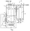
暖房給湯装置1は、給湯用の温水をタンク3に貯えるタンクユニットと、ヒートポンプサイクル装置2と、暖房用及び給湯用の温水が循環する温水回路と、給湯運転及び暖房運転を実施する際の各部の作動を制御する統合ECU100(制御装置)と、を備える。暖房給湯装置1は、浴槽、シャワー等の給湯端末へ出湯するために給湯用水としてタンク3内に熱量を貯える給湯運転を行い、ヒートポンプサイクル装置2で加熱した温水の熱量を暖房用熱交換器7に供給する暖房運転を行う。給湯運転と暖房運転は、同時に実施可能であり、それぞれ単独で実施可能である。
The heating and hot
暖房給湯装置1は、浴槽やシャワーなどへ出湯するときには、状況に応じて、例えば、深夜料金時間帯の系統電力を使用してタンク3の貯湯水のみを使用したり、昼間の太陽光発電装置の電力、または系統電力を使用して給湯用水を沸き上げて使用したりする。
The heating and hot
ヒートポンプサイクル装置2は、ヒートポンプ式加熱装置の一例であり、冷媒サイクルを流れる冷媒を熱交換媒体とし、温水回路を流れる水を沸き上げ、給湯用及び暖房用の熱量を生成する。ここで用いる冷媒は、二酸化炭素を主成分とする。ヒートポンプサイクル装置2は、統合ECU100と通信するヒートポンプECU101からの制御信号により作動するとともに、その作動状態はヒートポンプECU101を介して統合ECU100に出力される。
The heat
ヒートポンプサイクル装置2は、圧縮機20、水冷媒交換器21、減圧器22、空気冷媒熱交換器23及び排気用送風機24を備えている。圧縮機20は、二酸化炭素冷媒を圧縮、吐出する機器である。水冷媒交換器21は、冷媒側通路210と水側通路211を有し、対向するように内部を流れる冷媒と水が互いに熱交換するように構成されている。水冷媒交換器21は、圧縮機20で圧縮された冷媒と水側通路211の水との間で熱交換して温水を沸き上げる。減圧器22は、水冷媒熱交換器21を通過した高圧冷媒を低圧状態に減圧する。空気冷媒熱交換器23は、外気だけでなく室内空気を吸引する排気用送風機24によって空気から吸熱して、減圧器22で減圧された低圧冷媒を蒸発させる。この空気冷媒熱交換器23を通過した冷媒は、再度圧縮機20で圧縮されて高圧状態で吐出される。
The heat
タンクユニットは、給湯用の温水を貯えるタンク3と、水栓、風呂等の給湯端末へ出湯するために作動する各種弁、ポンプ等とを含む。タンクユニットは、統合ECU100と通信する貯湯ECU102からの制御信号により作動するとともに、その作動状態は貯湯ECU102を介して統合ECU100に出力される。
The tank unit includes a
タンク3は、例えば耐食性に優れた金属製のタンクであり、その外周部に図示しない断熱材が配置されており、高温の給湯用水を長時間に渡って保温することができる。タンク3の外壁面には、貯湯水の湯量、貯湯温度を検出するための複数個のタンクサーミスタ(図示せず)が設けられている。これらのサーミスタの検出温度信号は、それぞれ貯湯ECU102に入力されるようになっており、各水位レベルでのタンク内の水温や湯量を検出可能である。したがって、貯湯ECU102は、タンクサーミスタからの温度情報に基づいて、タンク3内の上部の沸き上げられた湯とタンク3内の下部の沸き上げられる前の水との境界位置を検出できる。さらに貯湯ECU102は、温度及び湯量の検出することにより、タンク3内に貯えられている貯熱量を算出することができる。
The
タンク3には、タンク3の内部に水道水を供給するための給水管34と、給湯用熱交換器39とタンク3の内部とを接続し、タンク3内の水が循環する貯熱用回路38と、給湯端末に繋がる給湯管36等からなる配管系統と、が接続されている。給湯管36は、タンク3の最上部の導出口31に接続されている。給水管34は、タンク3の最下部の導入口30に接続されている。給水管34は、タンク3に至る手前で分岐し、この分岐した給水管35は給湯管36に合流する。給水管35と給湯管36との合流部には混合弁37が設けられている。
The
導出口31と混合弁37との間に位置する給湯管36には、給湯管36を流れる温水の温度を検出する給湯サーミスタ(図示せず)が設けられている。給湯サーミスタにより検出される温度情報は、貯湯ECU102に出力され、混合弁37の作動制御に用いられる。貯湯ECU102は、混合弁37の開度を制御することによって、タンク3の上部から供給される温水と給水管35を通じて供給される水との混合割合を制御して、給湯端末へ出湯される給湯用水の温度を調整する。
The hot
貯熱用回路38は、タンク3内の下部の低温水が流出して給湯用熱交換器39で加熱されてタンク3内の上部に戻るように、給湯用熱交換器39を介してタンク3の下部と上部とを連絡する回路である。給湯用熱交換器39の一次側通路391と二次側通路390は、給湯用熱交換器39の内部通路を構成し、対向するように内部を流れる流体同士が互いに熱交換するように構成されている。
The
貯熱用回路38は、タンク3の最下部の導出口32に接続され、タンク3の最上部の導入口33に接続されている。貯熱用回路38には、給湯用熱交換器39の二次側通路390に流入する水温を検出する入水温度サーミスタ(図示せず)と、二次側通路390で加熱後の水温を検出する熱交換後温度サーミスタ(図示せず)と、ポンプ380と、が設けられている。各サーミスタの検出温度信号は、貯湯ECU102または統合ECU100に出力される。熱交換後温度サーミスタは、給湯用熱交換器39で熱交換された後の温水の温度を検出する熱媒体温度センサとして使用される。ポンプ380は、タンク3の下部の水を、貯熱用回路38を経由してタンク3の上部に戻す温水循環機能を果たす。
The
連絡通路50と給湯用通路52とを含む回路は、給湯用加熱回路である。連絡通路50は、給湯用熱交換器39(一次側通路391)と暖房用熱交換器7の内部通路を連結する通路と、水冷媒熱交換器21の水側通路211と、を連絡する通路である。したがって、連絡通路50は、その下流端で、暖房用熱交換器7に向かう暖房用通路51と、水側通路211に向かう給湯用通路52と、に二手に分岐する。給湯用通路52の途中には、給湯用熱交換器39の一次側通路391が存在する。暖房用通路51と給湯用通路52の分岐部には、流量調整弁5が設けられている。なお、給湯用加熱回路を構成する各通路は、各部間を接続する配管により形成される。
The circuit including the
暖房用熱交換器7は、室内暖房のための温風を生成するための暖房機器である。暖房用熱交換器7では、ヒートポンプサイクル装置2で加熱された温水が連絡通路50を経由して流量調整弁5で流量調整されて内部通路に流入すると、内部通路の周囲に放熱することにより、給気用送風機70により吸引される室外空気(外気等)を加熱する。暖房用熱交換器7で加熱された室外空気は、室内を暖房し、室内温度を上昇させることになる。暖房用熱交換器7で加熱された空気の温度は、吹出し温度検出手段である吹出し空気サーミスタ10によって電圧信号として検出される。統合ECU100は、検出された電圧信号を取得して室内への吹出し空気温度を算出する。
The heating heat exchanger 7 is a heating device for generating hot air for indoor heating. In the heat exchanger 7 for heating, when the hot water heated by the heat
室外空気が暖房用熱交換器7で加熱されるまでの空気経路の途中には、熱交換ユニット4が設けられている。熱交換ユニット4は、排気用送風機24により排気された室内空気と給気用送風機70により給気された室外空気とが熱交換する熱交換部を有する。この熱交換部は、室内空気が流通する内気通路40と、室外空気が流通する外気通路41とを含んで構成される。内気通路40と外気通路41は、それぞれを流通する室内空気と室外空気とが交差するときに熱交換するように構成されている。暖房給湯装置1が有する換気装置は、熱交換機能を有する熱交換ユニット4と、送風機能を有する排気用送風機24及び給気用送風機70とによって構成されている。また、熱交換ユニット4は、送風機を内蔵させるように構成してもよく、この送風機により室内空気または外気を取り入れるようにしてもよい。
A
流量調整弁5は、暖房用通路51及び給湯用通路52のそれぞれ開度を0%〜100%の範囲で調整することができる。統合ECU100は、後述する所定の条件の成立にしたがい、流量調整弁5による暖房用通路51側の開度と給湯用通路52側の開度をそれぞれ制御する。したがって、流量調整弁5は、ヒートポンプサイクル装置2によって加熱された温水を、暖房用熱交換器7に流通させる温水と給湯用熱交換器39に流通させる温水とに分配することが可能な流量調整手段の一例である。換言すれば、流量調整弁5は、暖房用熱交換器7への温水流量と給湯用熱交換器39への温水流量とを、必要な暖房能力、必要な給湯熱量に応じて制御できる流量調整手段として機能する。
The flow
給湯運転のみを実施する場合は、流量調整弁5は、暖房用通路51側の開度を0%(全閉)、給湯用通路52側の開度を100%(全開)に制御する。暖房運転のみを実施する場合は、流量調整弁5は、暖房用通路51側の開度を100%(全開)、給湯用通路52側の開度を0%(全閉)に制御する。暖房運転のみを実施する場合でも、必要な暖房能力が高くないときは、流量調整弁5は、暖房用通路51側の開度を必要な暖房能力に応じた開放率に制御し、暖房用通路51側の開度に応じて給湯用通路52側の開度を制御する。これにより、暖房用熱交換器7には、必要な暖房能力が得られる温水流量が分配され、残りの温水流量によって給湯用熱交換器39を介してタンク3に給湯用の熱量が貯熱される。
When only the hot water supply operation is performed, the flow
暖房用通路51は、その上流端が流量調整弁5であり、下流端が水冷媒熱交換器21の水側通路211の入口部まで延びる通路である。暖房用通路51には、上流側から順に、暖房用熱交換器7の内部通路、予熱用熱交換器6の内部通路、ポンプ54が設けられる。ポンプ54は、水冷媒熱交換器21の水側通路211を流出して連絡通路50を流れてきた温水を、給湯用通路52及び暖房用通路51の少なくとも一方を経由して水側通路211に戻す温水循環機能を果たす。
The
予熱用熱交換器6では、流量調整弁5で流量調節されて暖房用通路51を流通する温水が内部通路に流入すると、内部通路の周囲に放熱することにより、給気用送風機70により吸引される室外空気を加熱する。つまり、予熱用熱交換器6は、熱交換ユニット4の熱交換部で熱交換される前に室外空気を加熱する補助加熱装置として機能する。予熱用熱交換器6では、ヒートポンプサイクル装置2で加熱された温水が暖房用熱交換器7で放熱した後、内部通路に流入すると、温水の余った熱(余熱)が内部通路の周囲に放熱されることにより、熱交換ユニット4で熱交換される前の室外空気を予め加熱する。
In the preheating
給湯用通路52の下流端は、予熱用熱交換器6よりも下流であってヒートポンプサイクル装置2よりも上流に位置する通路部位(合流部53)で暖房用通路51に合流する。したがって、給湯用熱交換器39を流出した温水は、合流部53で、予熱用熱交換器6を流出してきた温水に合流するようになる。この合流部53が予熱用熱交換器6よりも下流に位置することにより、水冷媒熱交換器21の水側通路211に流入する水は、給湯用熱交換器39で放熱して温度低下した水と、暖房用熱交換器7及び予熱用熱交換器6で放熱して温度低下した水との混合水になる。
The downstream end of the hot
統合ECU100は、入力回路と、入力回路からの信号を用いて各種演算を実行するマイクロコンピュータと、出力回路と、を備えている。入力回路は、ユーザーが運転操作を設定できる運転操作部であるリモートコントローラ110からの信号、ヒートポンプECU101及び貯湯ECU102との通信信号、各種のサーミスタ等からの検出信号が入力される。出力回路は、マイクロコンピュータによる演算に基づいて、直接的に流量調整弁5、給気用送風機70、ポンプ54を制御する制御信号を出力する。出力回路は、ヒートポンプECU101、貯湯ECU102を介して間接的に、圧縮機20及び排気用送風機24、ポンプ380、混合弁37等の各種弁などを制御する制御信号を出力する。
The
リモートコントローラ110からの信号は、HEMS、台所設置や浴室設置の操作パネル等から統合ECU100への送信信号であり、例えば、出湯等の給湯自動運転を設定する信号、暖房運転を要求する信号、暖房運転及び給湯運転の同時実施する信号等である。統合ECU100のマイクロコンピュータは、各種のデータ、演算結果等を記憶する記憶手段としてのROM、RAM等を内蔵し、予め設定された制御プログラムや更新可能な制御プログラムを有し、給湯運転、暖房運転を制御する。ただし、タンク3へ熱量を貯える給湯運転を実施しているときに、タンク3ないが満水状態になった場合は、ヒートポンプサイクル装置2による温水沸き上げを停止することとする。この場合に、暖房運転を実施しているときは、暖房運転を継続し、必要な暖房能力が小さい場合には、暖房出力を下限レベルまで低下させるようにする。
A signal from the
上記構成の暖房給湯装置1において、給湯運転と暖房運転を同時に行う暖房給湯運転の作動について図3のフローチャートを参照して説明する。図3に示すフローチャートは、統合ECU100に、暖房運転及び給湯運転の要求が入力された場合、暖房運転要求のみが入力され、かつ必要な暖房能力が高くない場合に、開始される。図3に示す各ステップは、主に統合ECU100によって実行される。
In the heating and hot
まず、ステップ10で、吹出し空気サーミスタ10によって検出される室内への吹出し温度Taが吹出し目標温度Tset(あるいは室内の目標温度、室内の設定温度)よりも低いか否かを判定する。吹出し目標温度は、例えば、リモートコントローラ110の温度設定部が操作されることによりリモートコントローラ110から統合ECU100に送信された信号に基づいて決まる。
First, in
ステップ10で、TaがTsetよりも低いと判定すると、暖房能力がまだ足りないため、ステップ20で暖房用熱交換器7側の通路、すなわち暖房用通路51の開度を増大するように流量調整弁5を制御する。そして、この処理の後、再びステップ10に戻り、以降のステップにしたがって継続実行する。ステップ20の処理により、ヒートポンプサイクル装置2で沸き上げられた温水が前回よりも暖房用熱交換器7に多く流れるようになる。このため、暖房用熱交換器7を流れる温水温度の上昇に伴い、吹出し空気温度が上昇し、室内に供給される暖房能力を向上する制御が行われる。
If it is determined in
ステップ10で、TaがTset以上であると判定すると、次にステップ30でTaがTsetに所定温度αを加えた温度よりも高いか否かを判定する。所定温度αは、例えば約5℃に設定される。
If it is determined in
ステップ30で、Taが(Tset+α)よりも高いと判定すると、暖房能力が過剰であるため、ステップ40で暖房用熱交換器7側の通路、すなわち暖房用通路51の開度を減少するように流量調整弁5を制御する。そして、この処理の後、再びステップ10に戻り、以降のステップにしたがって継続実行する。ステップ40の処理により、ヒートポンプサイクル装置2で沸き上げられた温水が前回よりも暖房用熱交換器7に少なく流れるようになる。このため、暖房用熱交換器7を流れる温水温度の低下に伴い、吹出し空気温度が下降し、室内に供給される暖房能力を抑制する制御が行われる。
If it is determined in
また、ステップ30で、Taが(Tset+α)以下であると判定すると、再びステップ10に戻り、以降のステップにしたがって継続実行する。
If it is determined in
次に、第1実施形態の暖房給湯装置1がもたらす作用効果を以下に述べる。暖房給湯装置1は、換気装置と流量調整手段を備える。換気装置は、室内空気と室外空気とを熱交換する熱交換部(熱交換ユニット4)を有し、熱交換後の室内空気を室外に排気し、熱交換後の室外空気を室内に給気する。流量調整手段は、ヒートポンプサイクル装置2によって加熱された温水を、暖房用熱交換器7に流通させる温水と給湯用熱交換器39に流通させる温水とに分配することが可能である。
Next, the effect which the heating hot-
これによれば、ヒートポンプサイクル装置2で加熱した温水を暖房用熱交換器7と給湯用熱交換器39とに分配する温水通路を構成することにより、暖房運転と給湯運転の同時実施を実現しても、熱源である冷媒の経路を簡単化した装置を実現できる。
According to this, by implementing the hot water passage for distributing the hot water heated by the heat
例えば、必要な暖房能力が大きな場合に、換気装置が備えていない暖房給湯装置であると、ヒートポンプサイクル装置2の暖房負荷が大きくなる。これにより、必要な暖房能力が大きく、かつ給湯運転を同時に行おうとした場合に、ヒートポンプサイクル装置2の能力制約によって、暖房能力不足、もしくは給湯不可となり、暖房及び給湯の同時運転を成立できなくなる。
For example, when the required heating capacity is large, the heating load of the heat
そこで、暖房給湯装置1によれば、換気装置を有することにより、室外空気を昇温できるため、ヒートポンプサイクル装置2の暖房負荷を軽減できる。換言すれば、換気装置を有することで、ヒートポンプサイクル装置2の暖房負荷が軽減され、給湯運転を行うための余力を生み出すことができるため、給湯及び暖房の同時運転が可能となる。このように暖房給湯装置1は、室内空気と室外空気との熱交換を行った上で室内を換気する機能を併せ持つことにより、暖房負荷を低減し、室内空気の清浄性向上にも寄与する。
Then, according to the heating hot
したがって、暖房給湯装置1は、冷媒が流れる冷媒配管の長さを抑制し、かつ室内空気と室外空気の熱交換を伴った室内換気を行いつつ、ヒートポンプサイクル装置2からの熱量の分配が調整可能な暖房給湯運転を実施できる。これにより、暖房給湯装置1は、安定的かつ高効率な運転を実現できる。例えば、フロンガス等の環境への影響が大きい冷媒を使用する場合には、ヒートポンプサイクル装置2に封入する冷媒封入量を抑制できるため、環境にやさしい暖房給湯装置を提供できる。
Therefore, the heating and hot
また、流量調整手段によって暖房用熱交換器7の温水流量を調整することにより、ヒートポンプの下限加熱能力以下でも暖房能力を調整することができる。このように、暖房能力を幅広く調整できることで、室内温度を一定温度に制御しやすくなり、ユーザーのフィリングの改善が図れる。 Further, by adjusting the flow rate of the hot water in the heat exchanger 7 for heating by the flow rate adjusting means, the heating capability can be adjusted even below the lower limit heating capability of the heat pump. As described above, since the heating capacity can be widely adjusted, the room temperature can be easily controlled to a constant temperature, and the user's filling can be improved.
また、暖房給湯装置1によれば、熱交換ユニット4で熱交換される前に室外空気を加熱する補助加熱装置(例えば予熱用熱交換器6)を備える。これによれば、各種の補助加熱装置によって室外空気を予熱してから、熱交換ユニット4で室内空気と熱交換させることができる。したがって、室内の換気を実施することによる熱的損失を抑制することができ、エネルギー効率上、好ましい暖房給湯装置を提供できる。
Moreover, according to the heating hot-
また、暖房運転時、暖房給湯運転時に、ヒートポンプサイクル装置2によって加熱された温水は、暖房用熱交換器7を流出した後、予熱用熱交換器6に流入する。これにより、熱交換ユニット4で熱交換前の室外空気の予熱を、暖房用熱交換器7で放熱した後の温水の余熱を用いて実施することができる。さらに、外気温度が氷点下である場合は室外空気を直接熱交換ユニット4に送ると、熱交換ユニット4の内部で空気の水分が凍結し、換気風量の低下や装置の破損につながる。そこで、予熱用熱交換器6で温水の余熱を用いて予熱することにより、このような不具合を回避することができる。また、予熱用熱交換器6で温水の余熱をさらに放熱することにより、ヒートポンプサイクル装置2に戻る水温を低下させることができるので、COP(成績係数)を向上させることにも寄与する。
Moreover, the hot water heated by the heat
さらに、暖房と給湯の両方を行う暖房給湯運転時に、給湯用熱交換器39を流出した温水は、予熱用熱交換器6よりも下流であってヒートポンプサイクル装置2よりも上流に位置する通路部位(合流部53)で、予熱用熱交換器6を流出してきた温水に合流する。
Further, the hot water that has flowed out of the hot water
ヒートポンプ式の給湯装置では、予熱が必要になる低外気温度ほど、暖房のための温水回路の温水流量も増え、温水温度も上昇する。また、外気温度が高くなれば温水流量は減り、温水温度も低下する。この結果、低温度の外気ほど予熱用熱交換器で交換される熱量が大きくなる。一方で、給湯用熱交換器で熱交換後の温水温度は、タンクに残存している温水の温度によって異なるため、一般に外気とは無関係になる。仮に給湯用通路の合流箇所を予熱用熱交換器の前に設けると、残湯温度が高い場合は予熱用熱交換器に入る温水温度が高くなりすぎて、熱交換後の空気温度が室内空気温度よりも高くなり、熱交換ユニット内の熱交換が逆方向におきることがある。逆に残湯温度が低すぎる場合は、予熱用熱交換器に入る温水温度が低くなりすぎて、熱交換後の空気温度が十分に高くならないという問題が生じる。 In a heat pump hot water supply device, the lower the outside air temperature that requires preheating, the higher the hot water flow rate in the hot water circuit for heating and the higher the hot water temperature. Further, when the outside air temperature becomes high, the hot water flow rate decreases and the hot water temperature also decreases. As a result, the amount of heat exchanged by the preheating heat exchanger increases as the temperature of the outside air decreases. On the other hand, since the temperature of hot water after heat exchange in the heat exchanger for hot water supply differs depending on the temperature of hot water remaining in the tank, it is generally irrelevant to the outside air. If the joining point of the hot water supply passage is provided in front of the preheating heat exchanger, the temperature of the hot water entering the preheating heat exchanger becomes too high when the remaining hot water temperature is high, and the air temperature after heat exchange becomes room air. The temperature may become higher and the heat exchange in the heat exchange unit may occur in the opposite direction. Conversely, if the remaining hot water temperature is too low, the temperature of the hot water entering the preheating heat exchanger becomes too low, causing a problem that the air temperature after heat exchange does not become sufficiently high.
そこで、予熱用熱交換器6よりも下流でヒートポンプサイクル装置2よりも上流である合流部53で給湯用通路52を暖房用通路51に合流させることにより、給湯運転の状態に関係なく、予熱用熱交換器6の出口温度を安定させることができる。
Therefore, by joining the hot
また、暖房用熱交換器7は、熱交換ユニット4で熱交換された後であって室内に給気される前の室外空気に放熱するように設けられている。統合ECU100は、吹出し空気サーミスタ10によって検出される吹出し温度Taに応じて、流量調整手段の作動を制御して、暖房用熱交換器7に流通させる温水と給湯用熱交換器39に流通させる温水との流量割合を制御する。統合ECU100は、暖房給湯運転時に、吹出し温度Taが、吹出し目標温度よりも低い場合は、暖房用熱交換器7に流通させる温水の流量を増加させるように流量調整手段の作動を制御する。統合ECU100は、吹出し温度Taが、吹出し目標温度Tsetに所定温度を加えた温度よりも高い場合は、暖房用熱交換器7に流通させる温水の流量を減少させるように流量調整手段の作動を制御する。具体的には、流量調整弁5は、暖房給湯運転時に、暖房用通路51の開口面積と給湯用通路52の開口面積とを調整する。
Moreover, the heat exchanger 7 for heating is provided so that it may radiate heat to the outdoor air after the heat exchange by the
これによれば、流量調整弁5による暖房用通路51と給湯用通路52の開度比率の調整によって、暖房能力を幅広く調整でき、かつ微調整も可能となる。このような暖房能力調整によれば、室内温度をあまり変動させないようにして、一定温度に制御することが容易となる。
According to this, by adjusting the opening ratio of the
また、ヒートポンプサイクル装置2において、加熱作用を発揮する冷媒は、二酸化炭素を主成分とする冷媒である。これによれば、ヒートポンプサイクル装置2の冷媒が二酸化炭素である場合、沸き上げ可能な温度範囲が広いため、暖房給湯運転において、適合可能な給湯能力及び暖房能力を広く設定することができる。
Moreover, in the heat
(第2実施形態)
第2実施形態の暖房給湯装置1Aは、図4及び図5に示すように、第1実施形態の暖房給湯装置1に対して、流量調整手段が相違する。第2実施形態において、説明しない構成、作動、効果については第1実施形態と同様である。第2実施形態の流量調整手段は、暖房用通路51に設けられる暖房用ポンプ56と、給湯用通路52に設けられる給湯用ポンプ57と、から構成される。さらに暖房給湯装置1Aでは、暖房用通路51と給湯用通路52の分岐部55には流量調整弁5が設けられていない。
(Second Embodiment)
As shown in FIGS. 4 and 5, the heating hot
暖房用ポンプ56は、暖房用通路51において、暖房用熱交換器7よりも下流であって、予熱用熱交換器6よりも上流に位置する通路部位に設けられている。給湯用ポンプ57は、給湯用通路52において、給湯用熱交換器39よりも下流であって、合流部53よりも上流に位置する通路部位に設けられている。
The
統合ECU100Aは、吹出し空気サーミスタ10によって検出される吹出し温度Taに応じて、暖房用ポンプ56及び給湯用ポンプ57のそれぞれの回転数を制御して、駆動する温水流量を調整可能に制御することができる。暖房用ポンプ56は、暖房用熱交換器7に流通させる温水流量を調整する流量調整手段の機能を果たす。給湯用ポンプ57は、給湯用熱交換器39に流通させる温水流量を調整する流量調整手段の機能を果たす。
The integrated
上記構成の暖房給湯装置1Aにおいて、給湯運転と暖房運転を同時に行う暖房給湯運転の作動について図6のフローチャートを参照して説明する。図6に示すフローチャートは、統合ECU100Aに、暖房運転及び給湯運転の要求が入力された場合、暖房運転要求のみが入力され、かつ必要な暖房能力が高くない場合に、開始される。図6に示す各ステップは、主に統合ECU100Aによって実行される。
In the heating and hot
第1実施形態と同様のステップ10でTaがTsetよりも低いと判定すると、暖房能力がまだ足りない。このため、ステップ20Aで暖房用熱交換器の内部通路を流通する温水流量を増加させるために、暖房用ポンプ56の回転数を増大させるとともに給湯用ポンプ57の回転数を低下させるように制御し、出力(流量)を増大させる。そして、この処理の後、再びステップ10に戻り、以降のステップにしたがって継続実行する。ステップ20Aの処理により、ヒートポンプサイクル装置2で沸き上げられた温水が前回よりも暖房用熱交換器7に多く流れるようになる。このため、暖房用熱交換器7を流れる温水温度の上昇に伴い、吹出し空気温度が上昇し、室内に供給される暖房能力を向上する制御が行われる。
If it is determined in
ステップ10で、TaがTset以上であると判定し、さらにステップ30で、Taが(Tset+α)よりも高いと判定すると、暖房能力が過剰である。このため、ステップ40Aで暖房用熱交換器の内部通路を流通する温水流量を減少させるために、暖房用ポンプ56の回転数を低下させるとともに給湯用ポンプ57の回転数を増加させるように制御し、出力(流量)を減少させる。そして、この処理の後、再びステップ10に戻り、以降のステップにしたがって継続実行する。ステップ40Aの処理により、ヒートポンプサイクル装置2で沸き上げられた温水が前回よりも暖房用熱交換器7に少なく流れるようになる。このため、暖房用熱交換器7を流れる温水温度の低下に伴い、吹出し空気温度が下降し、室内に供給される暖房能力を抑制する制御が行われる。
If it is determined in
次に、第2実施形態の暖房給湯装置1Aの効果について説明する。暖房給湯装置1Aによれば、暖房用ポンプ56及び給湯用ポンプ57のそれぞれは、暖房と給湯の両方を行う暖房給湯運転時に、駆動する温水の流量を調整する。
Next, the effect of the heating hot
これによれば、暖房用ポンプ56及び給湯用ポンプ57のそれぞれを制御することによって、暖房用熱交換器7の温水流量を微調整可能になり、ヒートポンプの下限加熱能力以下でも暖房能力を調整することができる。このように、暖房能力を幅広く調整できることで、室内温度をあまり変動させないように一定温度に制御しやすくなる。
According to this, by controlling each of the
また、統合ECU100Aは、暖房給湯運転時に、吹出し空気サーミスタ10によって検出される吹出し温度Taが、吹出し目標温度Tsetよりも低い場合は、暖房用熱交換器7に流通させる温水の流量を増加させるように暖房用ポンプ56及び給湯用ポンプ57の作動を制御する(ステップ20A)。また、統合ECU100Aは、当該吹出し温度Taが、吹出し目標温度Tsetに所定温度αを加えた温度よりも高い場合は、暖房用熱交換器7に流通させる温水の流量を減少させるように暖房用ポンプ56及び給湯用ポンプ57の作動を制御する(ステップ40A)。
Further, the integrated
これによれば、吹出し温度Taと吹出し目標温度Tsetとに応じて、暖房用ポンプ56の出力を調整することにより、吹出し目標温度Tsetに近づけるように暖房能力を調整することができる。
According to this, by adjusting the output of the
(第3実施形態)
第3実施形態の暖房給湯装置1Bは、図7及び図8に示すように、第1実施形態の暖房給湯装置1と異なり、吹出し空気サーミスタ10の代わりに、熱交換器出口サーミスタ11(熱交換器出口温度検出手段)を用いる。例えば、熱交換器出口サーミスタ11は、暖房用熱交換器7の出口の配管に設けられ、暖房用熱交換器7の出口の温水温度Twを検出する。また、第3実施形態において、説明しない構成、作動、効果については第1実施形態と同様である。
(Third embodiment)
As shown in FIGS. 7 and 8, the heating and hot
暖房用熱交換器7で放熱した後の温水の温度は、熱交換器出口サーミスタ11によって電圧信号として検出される。統合ECU100Bは、検出された電圧信号を取得して、暖房用熱交換器7の出口の水温Twを算出する。統合ECU100Bは、検出されたに暖房用熱交換器7出口の水温Twに応じて、流量調整弁5の作動を制御して、暖房用熱交換器7に流通させる温水と給湯用熱交換器39に流通させる温水との流量割合を制御することができる。
The temperature of the hot water after radiating heat from the heating heat exchanger 7 is detected as a voltage signal by the heat
上記構成の暖房給湯装置1Bにおいて、給湯運転と暖房運転を同時に行う暖房給湯運転の作動について図9のフローチャートを参照して説明する。図9に示すフローチャートは、統合ECU100Bに、暖房運転及び給湯運転の要求が入力された場合、暖房運転要求のみが入力された場合に、開始される。図9に示す各ステップは、主に統合ECU100Aによって実行される。
In the heating and hot
まずステップ10Bで、熱交換器出口サーミスタ11によって水温Twが吹出し目標温度Tsetに所定温度βを加えた温度よりも低いか否かを判定する。ステップ10Bで、Twが(Tset+β)よりも低いと判定すると、暖房能力がまだ足りないため、第1実施形態と同様のステップ20で暖房用通路51の開度を増大するように流量調整弁5を制御する。そして、この処理の後、再びステップ10に戻り、以降のステップにしたがって継続実行する。
First, in step 10B, the heat
ステップ10で、Twが(Tset+β)以上であると判定すると、次にステップ30BでTwが(Tset+β)に所定温度αを加えた温度よりも高いか否かを判定する。
If it is determined in
ステップ30Bで、Twが(Tset+β+α)よりも高いと判定すると、暖房能力が過剰であるため、第1実施形態と同様のステップ40で暖房用通路51の開度を減少するように流量調整弁5を制御する。そして、この処理の後、再びステップ10に戻り、以降のステップにしたがって継続実行する。
If it is determined in step 30B that Tw is higher than (Tset + β + α), since the heating capacity is excessive, the flow
また、ステップ30で、Twが(Tset+β+α)以下であると判定すると、再びステップ10に戻り、以降のステップにしたがって継続実行する。
If it is determined in
(第4実施形態)
第4実施形態の暖房給湯装置1Cは、第1実施形態の暖房給湯装置1に対して、暖房用熱交換器8によって加熱される対象が相違する。すなわち、暖房用熱交換器8は、第1実施形態の暖房用熱交換器7のように室内に給気される外気(室外空気)を加熱するのではない。例えば、暖房用熱交換器8は、室内設置の温水式暖房器、床暖房機器等として用いられる。暖房用熱交換器8が床暖房機器である場合は、暖房用熱交換器8の内部通路を流通する温水は、床暖房パネル内を通過して放熱することにより床面を暖房する。
(Fourth embodiment)
The heating hot
暖房給湯装置1Cは、暖房用熱交換器8の採用に伴い、第1実施形態の吹出し空気サーミスタ10の代わりに、第3実施形態と同様に熱交換器出口サーミスタ11(熱交換器出口温度検出手段)を用いる。
With the adoption of the heat exchanger 8 for heating, the
また、第4実施形態において、説明しないすべての構成、作動、効果については第1実施形態、第3実施形態と同様である。 In the fourth embodiment, all configurations, operations, and effects that are not described are the same as those in the first embodiment and the third embodiment.
(他の実施形態)
上述の実施形態では、本発明の好ましい実施形態について説明したが、本発明は上述した実施形態に何ら制限されることなく、本発明の主旨を逸脱しない範囲において種々変形して実施することが可能である。
(Other embodiments)
In the above-described embodiment, the preferred embodiment of the present invention has been described. However, the present invention is not limited to the above-described embodiment, and various modifications can be made without departing from the spirit of the present invention. It is.
上記実施形態の構造は、あくまで例示であって、本発明の範囲はこれらの記載の範囲に限定されるものではない。本発明の範囲は、特許請求の範囲の記載によって示され、さらに特許請求の範囲の記載と均等の意味及び範囲内での全ての変更を含むものである。 The structure of the said embodiment is an illustration to the last, Comprising: The scope of the present invention is not limited to the range of these description. The scope of the present invention is indicated by the description of the scope of claims, and further includes meanings equivalent to the description of the scope of claims and all modifications within the scope.
上記実施形態の暖房給湯装置1〜1Cでは、水冷媒熱交換器21によって加熱された温水は流量調整弁5の開度制御に伴い、給湯用熱交換器39に流通させる形態であったが、他の形態として暖房給湯装置1Dに示すようにタンク3に流入させるようにしてもよい。図11に示すように、暖房給湯装置1Dは、流量制御弁5の一つの通路開閉部と合流部53(予熱用交換器6よりも下流の部位)とをタンク3の内部を介して連絡する給湯用通路52Dを備える。給湯用通路52Dは、流量制御弁5の一つの通路開閉部とタンク3の上部の導入口33とを連絡する通路と、タンク3の下部の導出口32と合流部53とを連絡する通路を含む。
In the heating and hot
暖房給湯装置1Dによれば、給湯運転時や暖房給湯運転時に、ポンプ54を駆動し、連絡通路50と給湯用通路52Dと連通させるように流量調整弁5の通路開口を制御することにより、水冷媒熱交換器21で加熱された温水を上部からタンク3内に貯める。これに伴い、タンク3の下部に位置する水は、流出して合流部53に至り、水冷媒熱交換器21の水側通路211に流入して再び水冷媒熱交換器21で加熱された後、タンク3内に上部から供給される。したがって、暖房給湯装置1Dによれば、給湯運転時や暖房給湯運転時に、ヒートポンプサイクル装置2の冷媒加熱作用により沸き上げた温水を、給湯用の熱交換器を介することなく直接タンク3の内部に貯めることができる。
According to the heating and hot
上記実施形態の暖房給湯装置は、換気ユニット4の熱交換部で熱交換される前に室外空気を加熱する補助加熱装置として、予熱用熱交換器6を備えるが、本発明に含まれる補助加熱装置はこの実施形態に限定されない。例えば、補助加熱装置には、通電により発熱するPTCヒータ、シーズヒータ、ハロゲンヒータ等の各種電気ヒータ等を採用することもできる。
Although the heating hot-water supply apparatus of the said embodiment is provided with the
また、上記実施形態において、ヒートポンプサイクル装置2を流れる作動冷媒は、二酸化炭素に限定されるものではなく、フロン等の他の冷媒であってもよい。
Moreover, in the said embodiment, the working refrigerant | coolant which flows through the heat
2…ヒートポンプサイクル装置(冷媒サイクル,ヒートポンプ式加熱装置)
3…タンク
4…熱交換ユニット(換気装置)
5…流量調整弁(流量調整手段)
6…予熱用熱交換器(補助加熱装置)
7,8…暖房用熱交換器
24…排気用送風機(換気装置)
39…給湯用熱交換器
56,57…ポンプ(流量調整手段)
70…給気用送風機(換気装置)
2. Heat pump cycle device (refrigerant cycle, heat pump heating device)
3 ...
5. Flow rate adjusting valve (flow rate adjusting means)
6 ... Preheat heat exchanger (auxiliary heating device)
7, 8 ... Heat exchanger for
39 ... Heat exchanger for
70 ... Air supply blower (ventilator)
Claims (8)
前記ヒートポンプ式加熱装置で加熱された温水が流入して周囲に放熱する暖房用熱交換器(7,8)と、
給湯用水を生成するために、前記ヒートポンプ式加熱装置で加熱された温水が流入する給湯用熱交換器(39)またはタンク(3)と、
室内空気と室外空気とを熱交換する熱交換部(40,41)を有し、前記熱交換後の前記室内空気を室外に排気し、前記熱交換後の前記室外空気を室内に給気する換気装置(4,24,70)と、
前記ヒートポンプ式加熱装置によって加熱された温水を、前記暖房用熱交換器に流通させる温水と前記給湯用熱交換器または前記タンクに流通させる温水とに分配することが可能な流量調整手段(5,56,57)と、
を備えることを特徴とする暖房給湯装置。 A heat pump heating device (2) for boiling hot water by the heating action of the refrigerant flowing in the refrigerant cycle;
A heat exchanger for heating (7, 8) in which hot water heated by the heat pump heating device flows in and dissipates heat to the surroundings;
A hot water supply heat exchanger (39) or a tank (3) into which hot water heated by the heat pump heating device flows to generate hot water supply water;
It has a heat exchanging part (40, 41) for exchanging heat between indoor air and outdoor air, exhausts the indoor air after the heat exchange to the outside, and supplies the outdoor air after the heat exchange into the room A ventilator (4, 24, 70);
The flow rate adjusting means (5, 5) capable of distributing the hot water heated by the heat pump heating device to the hot water flowing through the heating heat exchanger and the hot water flowing through the hot water supply heat exchanger or the tank. 56, 57),
A heating and hot water supply apparatus comprising:
前記予熱用熱交換器は、前記ヒートポンプ式加熱装置によって加熱された温水が前記暖房用熱交換器を流出した後、前記予熱用熱交換器に流入することにより、前記熱交換部で熱交換される前の前記室外空気を予熱し、
暖房と給湯の両方を行う暖房給湯運転時に、
前記ヒートポンプ式加熱装置によって加熱された温水は、前記暖房用熱交換器を流通する温水と前記給湯用熱交換器を流通する温水とに分配され、
前記給湯用熱交換器を流出した前記温水は、前記予熱用熱交換器よりも下流であって前記ヒートポンプ式加熱装置よりも上流に位置する通路部位で、前記予熱用熱交換器を流出してきた前記温水に合流することを特徴とする請求項2に記載の暖房給湯装置。 The auxiliary heating device includes a preheating heat exchanger (6) provided in a hot water passage downstream of the heating heat exchanger,
The preheating heat exchanger is heat-exchanged in the heat exchanging unit when hot water heated by the heat pump heating device flows out of the heating heat exchanger and then flows into the preheating heat exchanger. Preheat the outdoor air before
During heating and hot water operation that performs both heating and hot water supply,
The hot water heated by the heat pump heating device is distributed to hot water flowing through the heating heat exchanger and hot water flowing through the hot water supply heat exchanger,
The hot water that has flowed out of the hot water supply heat exchanger has flowed out of the preheating heat exchanger at a passage portion located downstream of the preheating heat exchanger and upstream of the heat pump heating device. The heating / hot water supply apparatus according to claim 2, wherein the hot water supply apparatus joins the warm water.
前記室外空気を前記暖房用熱交換器(7)で加熱した後、前記室内に吹き出される空気の温度を検出する吹出し温度検出手段(10)と、
前記吹出し温度検出手段によって検出される空気温度に応じて、前記流量調整手段の作動を制御して、前記暖房用熱交換器に流通させる温水と前記給湯用熱交換器または前記タンクに流通させる温水との流量割合を制御する制御装置(100)と、
を備え、
前記制御装置は、暖房と給湯の両方を行う暖房給湯運転時に、前記吹出し温度検出手段によって検出される空気温度が、
吹出し目標温度よりも低い場合は、前記暖房用熱交換器に流通させる温水の流量を増加させるように前記流量調整手段の作動を制御し、
前記吹出し目標温度に所定温度を加えた温度よりも高い場合は、前記暖房用熱交換器に流通させる温水の流量を減少させるように前記流量調整手段の作動を制御することを特徴とする請求項1ないし請求項3のいずれか一項に記載の暖房給湯装置。 The heating heat exchanger (7) is provided so as to dissipate heat to the outdoor air after being heat-exchanged by the heat exchange unit of the ventilation device and before being supplied to the room,
After the outdoor air is heated by the heating heat exchanger (7), blowout temperature detection means (10) for detecting the temperature of the air blown into the room;
Hot water to be circulated through the heating heat exchanger and the hot water exchanger or the tank by controlling the operation of the flow rate adjusting means according to the air temperature detected by the outlet temperature detecting means. A control device (100) for controlling the flow rate ratio of
With
In the heating and hot water supply operation in which the control device performs both heating and hot water supply, the air temperature detected by the blowing temperature detection means is
When the temperature is lower than the blow-out target temperature, the operation of the flow rate adjusting means is controlled so as to increase the flow rate of the hot water flowing through the heating heat exchanger,
The operation of the flow rate adjusting means is controlled so as to reduce the flow rate of the hot water flowing through the heating heat exchanger when the temperature is higher than a temperature obtained by adding a predetermined temperature to the blow-out target temperature. The heating hot-water supply apparatus as described in any one of Claim 1 thru | or 3.
前記流量調整手段は、前記暖房用通路と前記給湯用通路(52)との二手に分岐する分岐部に設けられる流量調整弁(5)であり、
前記流量調整弁は、暖房と給湯の両方を行う暖房給湯運転時に、前記暖房用通路の開口面積と前記給湯用通路の開口面積とを調整することを特徴とする請求項1ないし請求項4のいずれか一項に記載の暖房給湯装置。 The hot water passage (50) through which the hot water heated by the heat pump heating device flows includes a heating passage (51) toward the heating heat exchanger and a hot water passage (52) toward the hot water heat exchanger. ), And is configured to branch into two
The flow rate adjusting means is a flow rate adjusting valve (5) provided in a bifurcated branch between the heating passage and the hot water supply passage (52),
The flow rate adjusting valve adjusts the opening area of the passage for heating and the opening area of the passage for hot water supply during a heating and hot water supply operation in which both heating and hot water supply are performed. The heating hot water supply apparatus as described in any one.
前記流量調整手段は、前記暖房用通路に設けられる暖房用ポンプ(56)と、前記給湯用通路に設けられる給湯用ポンプ(57)と、から構成され、
前記暖房用ポンプ及び前記給湯用ポンプのそれぞれは、暖房と給湯の両方を行う暖房給湯運転時に、駆動する温水の流量を調整することを特徴とする請求項1ないし請求項4のいずれか一項に記載の暖房給湯装置。 The hot water passage (50) through which the hot water heated by the heat pump heating device flows includes a heating passage (51) toward the heating heat exchanger and a hot water passage (52) toward the hot water heat exchanger. ), And is configured to branch into two
The flow rate adjusting means includes a heating pump (56) provided in the heating passage and a hot water supply pump (57) provided in the hot water supply passage,
Each of the heating pump and the hot water supply pump adjusts the flow rate of the hot water to be driven during the heating hot water supply operation for performing both heating and hot water supply. The heating hot-water supply apparatus as described in.
前記熱交換器出口温度検出手段によって検出される水温に応じて、前記流量調整手段の作動を制御して、前記暖房用熱交換器に流通させる温水と前記給湯用熱交換器または前記タンクに流通させる温水との流量割合を制御する制御装置(100B)と、
を備えることを特徴とする請求項1ないし請求項3のいずれか一項に記載の暖房給湯装置。 Heat exchanger outlet temperature detection means (11) for detecting the temperature of hot water after radiating heat in the heating heat exchanger (7);
Depending on the water temperature detected by the heat exchanger outlet temperature detecting means, the operation of the flow rate adjusting means is controlled to flow to the hot water to be supplied to the heating heat exchanger and to the hot water supply heat exchanger or the tank. A control device (100B) for controlling a flow rate ratio with the hot water to be made;
The heating hot water supply apparatus according to any one of claims 1 to 3, further comprising:
Priority Applications (3)
| Application Number | Priority Date | Filing Date | Title |
|---|---|---|---|
| JP2013047147A JP5920251B2 (en) | 2013-03-08 | 2013-03-08 | Heating and hot water supply equipment |
| DE112014001194.0T DE112014001194T5 (en) | 2013-03-08 | 2014-02-12 | Heating and hot water supply device |
| PCT/JP2014/000707 WO2014136384A1 (en) | 2013-03-08 | 2014-02-12 | Heating and hot water supply device |
Applications Claiming Priority (1)
| Application Number | Priority Date | Filing Date | Title |
|---|---|---|---|
| JP2013047147A JP5920251B2 (en) | 2013-03-08 | 2013-03-08 | Heating and hot water supply equipment |
Publications (2)
| Publication Number | Publication Date |
|---|---|
| JP2014173792A true JP2014173792A (en) | 2014-09-22 |
| JP5920251B2 JP5920251B2 (en) | 2016-05-18 |
Family
ID=51490923
Family Applications (1)
| Application Number | Title | Priority Date | Filing Date |
|---|---|---|---|
| JP2013047147A Expired - Fee Related JP5920251B2 (en) | 2013-03-08 | 2013-03-08 | Heating and hot water supply equipment |
Country Status (3)
| Country | Link |
|---|---|
| JP (1) | JP5920251B2 (en) |
| DE (1) | DE112014001194T5 (en) |
| WO (1) | WO2014136384A1 (en) |
Cited By (4)
| Publication number | Priority date | Publication date | Assignee | Title |
|---|---|---|---|---|
| JP2016080194A (en) * | 2014-10-09 | 2016-05-16 | リンナイ株式会社 | Heat pump system |
| KR20200049022A (en) * | 2018-10-31 | 2020-05-08 | 주식회사 도우이앤이 | Exhaust heat recovery system of air conditioning system |
| JPWO2020240685A1 (en) * | 2019-05-28 | 2020-12-03 | ||
| CN113854928A (en) * | 2021-11-18 | 2021-12-31 | 佛山市顺德区乐普达电机有限公司 | Motor structure with heating function for dish washing machine |
Families Citing this family (5)
| Publication number | Priority date | Publication date | Assignee | Title |
|---|---|---|---|---|
| RU2629169C1 (en) * | 2016-05-30 | 2017-08-24 | Федеральное государственное бюджетное образовательное учреждение высшего образования "Липецкий государственный технический университет" (ЛГТУ) | Subscriber input of heat supply system of building |
| FI129149B (en) * | 2016-09-16 | 2021-08-13 | Byro Energiatekniikka Oy | Exhaust air heat pump apparatus and method of processing exhaust air |
| WO2019064335A1 (en) * | 2017-09-26 | 2019-04-04 | 三菱電機株式会社 | Refrigeration cycle device |
| FR3079287B1 (en) * | 2018-03-20 | 2022-09-09 | Andre Batt | HYBRID HEATING SYSTEM |
| EP3572732A1 (en) * | 2018-05-25 | 2019-11-27 | Weider Wärmepumpen GmbH | Heat pump heating device for heating of a building or an industrial water storage device |
Citations (6)
| Publication number | Priority date | Publication date | Assignee | Title |
|---|---|---|---|---|
| JPS60182630U (en) * | 1984-05-15 | 1985-12-04 | 三菱電機株式会社 | air conditioning ventilation fan |
| JPH06323593A (en) * | 1993-05-19 | 1994-11-25 | Sekisui Chem Co Ltd | Heat exchange type ventilator |
| JP2000074396A (en) * | 1998-08-27 | 2000-03-14 | Noritz Corp | Method for controlling heating terminal |
| JP2009216346A (en) * | 2008-03-12 | 2009-09-24 | Panasonic Electric Works Co Ltd | Hot water storage type hot water supply system |
| JP2010019477A (en) * | 2008-07-10 | 2010-01-28 | Corona Corp | Storage type hot water supplying and heating apparatus |
| JP2010203685A (en) * | 2009-03-03 | 2010-09-16 | Mitsubishi Electric Corp | Air conditioning device and method for controlling the same |
-
2013
- 2013-03-08 JP JP2013047147A patent/JP5920251B2/en not_active Expired - Fee Related
-
2014
- 2014-02-12 WO PCT/JP2014/000707 patent/WO2014136384A1/en active Application Filing
- 2014-02-12 DE DE112014001194.0T patent/DE112014001194T5/en not_active Withdrawn
Patent Citations (6)
| Publication number | Priority date | Publication date | Assignee | Title |
|---|---|---|---|---|
| JPS60182630U (en) * | 1984-05-15 | 1985-12-04 | 三菱電機株式会社 | air conditioning ventilation fan |
| JPH06323593A (en) * | 1993-05-19 | 1994-11-25 | Sekisui Chem Co Ltd | Heat exchange type ventilator |
| JP2000074396A (en) * | 1998-08-27 | 2000-03-14 | Noritz Corp | Method for controlling heating terminal |
| JP2009216346A (en) * | 2008-03-12 | 2009-09-24 | Panasonic Electric Works Co Ltd | Hot water storage type hot water supply system |
| JP2010019477A (en) * | 2008-07-10 | 2010-01-28 | Corona Corp | Storage type hot water supplying and heating apparatus |
| JP2010203685A (en) * | 2009-03-03 | 2010-09-16 | Mitsubishi Electric Corp | Air conditioning device and method for controlling the same |
Cited By (7)
| Publication number | Priority date | Publication date | Assignee | Title |
|---|---|---|---|---|
| JP2016080194A (en) * | 2014-10-09 | 2016-05-16 | リンナイ株式会社 | Heat pump system |
| KR20200049022A (en) * | 2018-10-31 | 2020-05-08 | 주식회사 도우이앤이 | Exhaust heat recovery system of air conditioning system |
| KR102110874B1 (en) * | 2018-10-31 | 2020-05-14 | 주식회사 도우이앤이 | Exhaust heat recovery system of air conditioning system |
| JPWO2020240685A1 (en) * | 2019-05-28 | 2020-12-03 | ||
| JP7199529B2 (en) | 2019-05-28 | 2023-01-05 | 三菱電機株式会社 | Control device, air environment adjustment system, air environment adjustment method, program, and recording medium |
| CN113854928A (en) * | 2021-11-18 | 2021-12-31 | 佛山市顺德区乐普达电机有限公司 | Motor structure with heating function for dish washing machine |
| CN113854928B (en) * | 2021-11-18 | 2022-09-02 | 佛山市顺德区乐普达电机有限公司 | Motor structure with heating function for dish washing machine |
Also Published As
| Publication number | Publication date |
|---|---|
| WO2014136384A1 (en) | 2014-09-12 |
| DE112014001194T5 (en) | 2015-11-19 |
| JP5920251B2 (en) | 2016-05-18 |
Similar Documents
| Publication | Publication Date | Title |
|---|---|---|
| JP5920251B2 (en) | Heating and hot water supply equipment | |
| JP6320633B2 (en) | Heat pump equipment | |
| US10551074B2 (en) | Heating and hot water supply system | |
| JP5492346B2 (en) | Air conditioning and hot water supply system | |
| EP3115701B1 (en) | Heat-pump hot water generator | |
| WO2015115434A1 (en) | Air conditioner system | |
| JP6471672B2 (en) | Hot water heating system | |
| JP2015161465A (en) | CO2 water heater | |
| JP2008014585A (en) | Brine heat radiation type heating apparatus | |
| JP2014016075A (en) | Hybrid system | |
| WO2013080297A1 (en) | Air conditioning/hot water supply system | |
| JP2013181682A (en) | Heat pump heat source system | |
| JP6354627B2 (en) | Heat pump hot water heating and heating system | |
| JP5176474B2 (en) | Heat pump water heater | |
| JP2009287898A (en) | Heat pump type hot water heat utilizing system | |
| JP4194213B2 (en) | Hot water storage hot water source | |
| JP2006078146A (en) | Heat pump, floor heating device, and air conditioner | |
| JP2003056905A (en) | Water heater | |
| KR20170042486A (en) | Heating device | |
| JP2010054145A (en) | Heat pump water heater | |
| JP2002295899A (en) | Hot-water storage type water-heating heat source | |
| JP3960912B2 (en) | Hot water storage hot water source | |
| JP4382309B2 (en) | Hot water storage water heater | |
| JP7399321B2 (en) | Chiller system and air conditioner with chiller system | |
| JP5741256B2 (en) | Hot water storage water heater |
Legal Events
| Date | Code | Title | Description |
|---|---|---|---|
| A621 | Written request for application examination |
Free format text: JAPANESE INTERMEDIATE CODE: A621 Effective date: 20150520 |
|
| A131 | Notification of reasons for refusal |
Free format text: JAPANESE INTERMEDIATE CODE: A131 Effective date: 20160112 |
|
| A521 | Request for written amendment filed |
Free format text: JAPANESE INTERMEDIATE CODE: A523 Effective date: 20160224 |
|
| TRDD | Decision of grant or rejection written | ||
| A01 | Written decision to grant a patent or to grant a registration (utility model) |
Free format text: JAPANESE INTERMEDIATE CODE: A01 Effective date: 20160315 |
|
| A61 | First payment of annual fees (during grant procedure) |
Free format text: JAPANESE INTERMEDIATE CODE: A61 Effective date: 20160328 |
|
| R151 | Written notification of patent or utility model registration |
Ref document number: 5920251 Country of ref document: JP Free format text: JAPANESE INTERMEDIATE CODE: R151 |
|
| S802 | Written request for registration of partial abandonment of right |
Free format text: JAPANESE INTERMEDIATE CODE: R311802 |
|
| R350 | Written notification of registration of transfer |
Free format text: JAPANESE INTERMEDIATE CODE: R350 |
|
| R250 | Receipt of annual fees |
Free format text: JAPANESE INTERMEDIATE CODE: R250 |
|
| R250 | Receipt of annual fees |
Free format text: JAPANESE INTERMEDIATE CODE: R250 |
|
| LAPS | Cancellation because of no payment of annual fees |