EP3572732A1 - Heat pump heating device for heating of a building or an industrial water storage device - Google Patents
Heat pump heating device for heating of a building or an industrial water storage device Download PDFInfo
- Publication number
- EP3572732A1 EP3572732A1 EP18174262.8A EP18174262A EP3572732A1 EP 3572732 A1 EP3572732 A1 EP 3572732A1 EP 18174262 A EP18174262 A EP 18174262A EP 3572732 A1 EP3572732 A1 EP 3572732A1
- Authority
- EP
- European Patent Office
- Prior art keywords
- heat
- heat exchanger
- air
- heat source
- heating
- Prior art date
- Legal status (The legal status is an assumption and is not a legal conclusion. Google has not performed a legal analysis and makes no representation as to the accuracy of the status listed.)
- Withdrawn
Links
- 238000010438 heat treatment Methods 0.000 title claims abstract description 56
- 239000008235 industrial water Substances 0.000 title 1
- 239000012530 fluid Substances 0.000 claims abstract description 53
- 238000009423 ventilation Methods 0.000 claims abstract description 25
- XLYOFNOQVPJJNP-UHFFFAOYSA-N water Substances O XLYOFNOQVPJJNP-UHFFFAOYSA-N 0.000 claims abstract description 12
- 238000005086 pumping Methods 0.000 claims abstract description 5
- 239000012267 brine Substances 0.000 claims abstract description 4
- HPALAKNZSZLMCH-UHFFFAOYSA-M sodium;chloride;hydrate Chemical compound O.[Na+].[Cl-] HPALAKNZSZLMCH-UHFFFAOYSA-M 0.000 claims abstract description 4
- 239000008236 heating water Substances 0.000 claims abstract description 3
- 238000000034 method Methods 0.000 claims description 2
- 230000008569 process Effects 0.000 claims description 2
- 239000000523 sample Substances 0.000 description 22
- 230000008901 benefit Effects 0.000 description 7
- 238000011084 recovery Methods 0.000 description 7
- 238000010586 diagram Methods 0.000 description 6
- 230000009467 reduction Effects 0.000 description 4
- 238000010257 thawing Methods 0.000 description 4
- 230000015572 biosynthetic process Effects 0.000 description 3
- LYCAIKOWRPUZTN-UHFFFAOYSA-N Ethylene glycol Chemical compound OCCO LYCAIKOWRPUZTN-UHFFFAOYSA-N 0.000 description 2
- 230000033228 biological regulation Effects 0.000 description 2
- 238000004364 calculation method Methods 0.000 description 2
- 238000001816 cooling Methods 0.000 description 2
- 238000011161 development Methods 0.000 description 2
- 230000018109 developmental process Effects 0.000 description 2
- 238000000605 extraction Methods 0.000 description 2
- 230000010354 integration Effects 0.000 description 2
- 230000005923 long-lasting effect Effects 0.000 description 2
- 238000004519 manufacturing process Methods 0.000 description 2
- 230000001932 seasonal effect Effects 0.000 description 2
- 239000002689 soil Substances 0.000 description 2
- 230000007704 transition Effects 0.000 description 2
- 241000270295 Serpentes Species 0.000 description 1
- 239000003990 capacitor Substances 0.000 description 1
- 230000008859 change Effects 0.000 description 1
- 230000001276 controlling effect Effects 0.000 description 1
- 230000007423 decrease Effects 0.000 description 1
- 230000001419 dependent effect Effects 0.000 description 1
- 238000007599 discharging Methods 0.000 description 1
- 238000005553 drilling Methods 0.000 description 1
- 230000000694 effects Effects 0.000 description 1
- 238000001704 evaporation Methods 0.000 description 1
- 238000009499 grossing Methods 0.000 description 1
- 239000003673 groundwater Substances 0.000 description 1
- WGCNASOHLSPBMP-UHFFFAOYSA-N hydroxyacetaldehyde Natural products OCC=O WGCNASOHLSPBMP-UHFFFAOYSA-N 0.000 description 1
- 230000006872 improvement Effects 0.000 description 1
- 238000009434 installation Methods 0.000 description 1
- 238000009413 insulation Methods 0.000 description 1
- 230000008092 positive effect Effects 0.000 description 1
- 230000001105 regulatory effect Effects 0.000 description 1
- 238000003303 reheating Methods 0.000 description 1
- 150000003839 salts Chemical class 0.000 description 1
- 239000010865 sewage Substances 0.000 description 1
- 238000004088 simulation Methods 0.000 description 1
- 238000011144 upstream manufacturing Methods 0.000 description 1
- 239000002699 waste material Substances 0.000 description 1
Images


Classifications
-
- F—MECHANICAL ENGINEERING; LIGHTING; HEATING; WEAPONS; BLASTING
- F24—HEATING; RANGES; VENTILATING
- F24D—DOMESTIC- OR SPACE-HEATING SYSTEMS, e.g. CENTRAL HEATING SYSTEMS; DOMESTIC HOT-WATER SUPPLY SYSTEMS; ELEMENTS OR COMPONENTS THEREFOR
- F24D19/00—Details
- F24D19/10—Arrangement or mounting of control or safety devices
- F24D19/1006—Arrangement or mounting of control or safety devices for water heating systems
- F24D19/1009—Arrangement or mounting of control or safety devices for water heating systems for central heating
- F24D19/1039—Arrangement or mounting of control or safety devices for water heating systems for central heating the system uses a heat pump
-
- F—MECHANICAL ENGINEERING; LIGHTING; HEATING; WEAPONS; BLASTING
- F24—HEATING; RANGES; VENTILATING
- F24D—DOMESTIC- OR SPACE-HEATING SYSTEMS, e.g. CENTRAL HEATING SYSTEMS; DOMESTIC HOT-WATER SUPPLY SYSTEMS; ELEMENTS OR COMPONENTS THEREFOR
- F24D3/00—Hot-water central heating systems
- F24D3/18—Hot-water central heating systems using heat pumps
-
- F—MECHANICAL ENGINEERING; LIGHTING; HEATING; WEAPONS; BLASTING
- F24—HEATING; RANGES; VENTILATING
- F24D—DOMESTIC- OR SPACE-HEATING SYSTEMS, e.g. CENTRAL HEATING SYSTEMS; DOMESTIC HOT-WATER SUPPLY SYSTEMS; ELEMENTS OR COMPONENTS THEREFOR
- F24D5/00—Hot-air central heating systems; Exhaust gas central heating systems
- F24D5/02—Hot-air central heating systems; Exhaust gas central heating systems operating with discharge of hot air into the space or area to be heated
-
- F—MECHANICAL ENGINEERING; LIGHTING; HEATING; WEAPONS; BLASTING
- F24—HEATING; RANGES; VENTILATING
- F24D—DOMESTIC- OR SPACE-HEATING SYSTEMS, e.g. CENTRAL HEATING SYSTEMS; DOMESTIC HOT-WATER SUPPLY SYSTEMS; ELEMENTS OR COMPONENTS THEREFOR
- F24D9/00—Central heating systems employing combinations of heat transfer fluids covered by two or more of groups F24D1/00 - F24D7/00
-
- F—MECHANICAL ENGINEERING; LIGHTING; HEATING; WEAPONS; BLASTING
- F24—HEATING; RANGES; VENTILATING
- F24F—AIR-CONDITIONING; AIR-HUMIDIFICATION; VENTILATION; USE OF AIR CURRENTS FOR SCREENING
- F24F12/00—Use of energy recovery systems in air conditioning, ventilation or screening
- F24F12/001—Use of energy recovery systems in air conditioning, ventilation or screening with heat-exchange between supplied and exhausted air
- F24F12/006—Use of energy recovery systems in air conditioning, ventilation or screening with heat-exchange between supplied and exhausted air using an air-to-air heat exchanger
-
- F—MECHANICAL ENGINEERING; LIGHTING; HEATING; WEAPONS; BLASTING
- F24—HEATING; RANGES; VENTILATING
- F24F—AIR-CONDITIONING; AIR-HUMIDIFICATION; VENTILATION; USE OF AIR CURRENTS FOR SCREENING
- F24F5/00—Air-conditioning systems or apparatus not covered by F24F1/00 or F24F3/00, e.g. using solar heat or combined with household units such as an oven or water heater
- F24F5/0096—Air-conditioning systems or apparatus not covered by F24F1/00 or F24F3/00, e.g. using solar heat or combined with household units such as an oven or water heater combined with domestic apparatus
-
- F—MECHANICAL ENGINEERING; LIGHTING; HEATING; WEAPONS; BLASTING
- F24—HEATING; RANGES; VENTILATING
- F24D—DOMESTIC- OR SPACE-HEATING SYSTEMS, e.g. CENTRAL HEATING SYSTEMS; DOMESTIC HOT-WATER SUPPLY SYSTEMS; ELEMENTS OR COMPONENTS THEREFOR
- F24D2200/00—Heat sources or energy sources
- F24D2200/11—Geothermal energy
-
- F—MECHANICAL ENGINEERING; LIGHTING; HEATING; WEAPONS; BLASTING
- F24—HEATING; RANGES; VENTILATING
- F24D—DOMESTIC- OR SPACE-HEATING SYSTEMS, e.g. CENTRAL HEATING SYSTEMS; DOMESTIC HOT-WATER SUPPLY SYSTEMS; ELEMENTS OR COMPONENTS THEREFOR
- F24D2200/00—Heat sources or energy sources
- F24D2200/12—Heat pump
-
- F—MECHANICAL ENGINEERING; LIGHTING; HEATING; WEAPONS; BLASTING
- F24—HEATING; RANGES; VENTILATING
- F24D—DOMESTIC- OR SPACE-HEATING SYSTEMS, e.g. CENTRAL HEATING SYSTEMS; DOMESTIC HOT-WATER SUPPLY SYSTEMS; ELEMENTS OR COMPONENTS THEREFOR
- F24D2200/00—Heat sources or energy sources
- F24D2200/16—Waste heat
- F24D2200/22—Ventilation air
-
- Y—GENERAL TAGGING OF NEW TECHNOLOGICAL DEVELOPMENTS; GENERAL TAGGING OF CROSS-SECTIONAL TECHNOLOGIES SPANNING OVER SEVERAL SECTIONS OF THE IPC; TECHNICAL SUBJECTS COVERED BY FORMER USPC CROSS-REFERENCE ART COLLECTIONS [XRACs] AND DIGESTS
- Y02—TECHNOLOGIES OR APPLICATIONS FOR MITIGATION OR ADAPTATION AGAINST CLIMATE CHANGE
- Y02B—CLIMATE CHANGE MITIGATION TECHNOLOGIES RELATED TO BUILDINGS, e.g. HOUSING, HOUSE APPLIANCES OR RELATED END-USER APPLICATIONS
- Y02B10/00—Integration of renewable energy sources in buildings
- Y02B10/40—Geothermal heat-pumps
-
- Y—GENERAL TAGGING OF NEW TECHNOLOGICAL DEVELOPMENTS; GENERAL TAGGING OF CROSS-SECTIONAL TECHNOLOGIES SPANNING OVER SEVERAL SECTIONS OF THE IPC; TECHNICAL SUBJECTS COVERED BY FORMER USPC CROSS-REFERENCE ART COLLECTIONS [XRACs] AND DIGESTS
- Y02—TECHNOLOGIES OR APPLICATIONS FOR MITIGATION OR ADAPTATION AGAINST CLIMATE CHANGE
- Y02B—CLIMATE CHANGE MITIGATION TECHNOLOGIES RELATED TO BUILDINGS, e.g. HOUSING, HOUSE APPLIANCES OR RELATED END-USER APPLICATIONS
- Y02B10/00—Integration of renewable energy sources in buildings
- Y02B10/70—Hybrid systems, e.g. uninterruptible or back-up power supplies integrating renewable energies
-
- Y—GENERAL TAGGING OF NEW TECHNOLOGICAL DEVELOPMENTS; GENERAL TAGGING OF CROSS-SECTIONAL TECHNOLOGIES SPANNING OVER SEVERAL SECTIONS OF THE IPC; TECHNICAL SUBJECTS COVERED BY FORMER USPC CROSS-REFERENCE ART COLLECTIONS [XRACs] AND DIGESTS
- Y02—TECHNOLOGIES OR APPLICATIONS FOR MITIGATION OR ADAPTATION AGAINST CLIMATE CHANGE
- Y02B—CLIMATE CHANGE MITIGATION TECHNOLOGIES RELATED TO BUILDINGS, e.g. HOUSING, HOUSE APPLIANCES OR RELATED END-USER APPLICATIONS
- Y02B30/00—Energy efficient heating, ventilation or air conditioning [HVAC]
- Y02B30/12—Hot water central heating systems using heat pumps
-
- Y—GENERAL TAGGING OF NEW TECHNOLOGICAL DEVELOPMENTS; GENERAL TAGGING OF CROSS-SECTIONAL TECHNOLOGIES SPANNING OVER SEVERAL SECTIONS OF THE IPC; TECHNICAL SUBJECTS COVERED BY FORMER USPC CROSS-REFERENCE ART COLLECTIONS [XRACs] AND DIGESTS
- Y02—TECHNOLOGIES OR APPLICATIONS FOR MITIGATION OR ADAPTATION AGAINST CLIMATE CHANGE
- Y02B—CLIMATE CHANGE MITIGATION TECHNOLOGIES RELATED TO BUILDINGS, e.g. HOUSING, HOUSE APPLIANCES OR RELATED END-USER APPLICATIONS
- Y02B30/00—Energy efficient heating, ventilation or air conditioning [HVAC]
- Y02B30/52—Heat recovery pumps, i.e. heat pump based systems or units able to transfer the thermal energy from one area of the premises or part of the facilities to a different one, improving the overall efficiency
-
- Y—GENERAL TAGGING OF NEW TECHNOLOGICAL DEVELOPMENTS; GENERAL TAGGING OF CROSS-SECTIONAL TECHNOLOGIES SPANNING OVER SEVERAL SECTIONS OF THE IPC; TECHNICAL SUBJECTS COVERED BY FORMER USPC CROSS-REFERENCE ART COLLECTIONS [XRACs] AND DIGESTS
- Y02—TECHNOLOGIES OR APPLICATIONS FOR MITIGATION OR ADAPTATION AGAINST CLIMATE CHANGE
- Y02B—CLIMATE CHANGE MITIGATION TECHNOLOGIES RELATED TO BUILDINGS, e.g. HOUSING, HOUSE APPLIANCES OR RELATED END-USER APPLICATIONS
- Y02B30/00—Energy efficient heating, ventilation or air conditioning [HVAC]
- Y02B30/56—Heat recovery units
Landscapes
- Engineering & Computer Science (AREA)
- Chemical & Material Sciences (AREA)
- Combustion & Propulsion (AREA)
- Mechanical Engineering (AREA)
- General Engineering & Computer Science (AREA)
- Physics & Mathematics (AREA)
- Thermal Sciences (AREA)
- Life Sciences & Earth Sciences (AREA)
- Sustainable Development (AREA)
- Steam Or Hot-Water Central Heating Systems (AREA)
- Other Air-Conditioning Systems (AREA)
Abstract
Es wird eine Wärmepumpenheizvorrichtung zum Heizen eines Gebäudes und/oder eines Brauchwasserspeichers (7) mit einer Wärmepumpe (4), wobei ein Wärmequellenkreislauf (3) wenigstens die Wärmepumpe (4) und einen Wärmequellen-Wärmetauscher (5) zum Nutzen von Wärmeenergie einer Wärmequelle, insbesondere eines Erdkörpers oder dergleichen, sowie eine Pumpe (15) zum Pumpen und/oder Umwälzen eines Wärmequellenfluids, insbesondere einer Sole, umfasst, wobei ein Heizkreislauf (6) wenigstens die Wärmepumpe (4) und einen von einem Heizfluid, insbesondere einem Heizwasser, durchströmbaren Heizkörper (7), insbesondere Flächenheizkörper und/oder Radiator, und/oder den Brauchwasserspeicher (7) sowie eine Heizpumpe zum Pumpen und/oder Umwälzen des Heizfluids umfasst, wobei eine Lüftungsanlage (26) wenigstens eine Wärmetauschereinheit (9 zur Wärmeübertragung zwischen einem aus dem Gebäude ausströmenden, ersten Luftstrom (10, 13) und einem in das Gebäude einströmenden, zweiten Luftstrom (8, 12) aufweist, wobei der Wärmequellenkreislauf (3) wenigstens einen ersten, von dem Wärmequellenfluid durchströmbaren Luft-Wärmetauscher (1) zur Wärmeübertragung zwischen einem der Luftströme (8, 10, 12, 13) der Lüftungsanlage (26) und dem Wärmequellenfluid aufweist, vorgeschlagen, die die Nachteile des Stands der Technik wenigstens teilweise verbessert, insbesondere bei tiefen (Außen-) Temperaturen und/oder die Nutzbarkeit der Wärmequelle verbessert. Dies wird erfindungsgemäß dadurch erreicht, dass der Wärmequellenkreislauf (3) wenigstens einen zweiten, von dem Wärmequellenfluid durchströmbaren Luft-Wärmetauscher (2) zur Wärmeübertragung zwischen einem der Luftströme (8, 10, 12, 13) der Lüftungsanlage (26) und dem Wärmequellenfluid aufweist.A heat pump heating device is used for heating a building and / or a domestic water storage tank (7) with a heat pump (4), a heat source circuit (3) at least the heat pump (4) and a heat source heat exchanger (5) for utilizing heat energy from a heat source, in particular a body of earth or the like, as well as a pump (15) for pumping and / or circulating a heat source fluid, in particular a brine, wherein a heating circuit (6) at least the heat pump (4) and one of a heating fluid, in particular heating water, can flow through Heating element (7), in particular surface heating element and / or radiator, and / or the domestic water tank (7) as well as a heating pump for pumping and / or circulating the heating fluid, wherein a ventilation system (26) comprises at least one heat exchanger unit (9 for heat transfer between one of the First air flow (10, 13) flowing out of the building and a second air flow (8, 12) flowing into the building, wherein the heat source circuit (3) has at least one first air heat exchanger (1) through which the heat source fluid can flow for heat transfer between one of the air flows (8, 10, 12, 13) of the ventilation system (26) and the heat source fluid, which has the disadvantages of the prior art is at least partially improved, in particular at low (outside) temperatures and / or the usability of the heat source is improved. This is achieved according to the invention in that the heat source circuit (3) has at least one second air heat exchanger (2) through which the heat source fluid can flow for heat transfer between one of the air flows (8, 10, 12, 13) of the ventilation system (26) and the heat source fluid .
Description
Die Erfindung betrifft eine Wärmepumpenheizvorrichtung zum Heizen eines Gebäudes und/oder eines Brauchwasserspeichers mit einer Wärmepumpe, wobei ein Wärmequellenkreislauf wenigstens die Wärmepumpe und einen Wärmequellen-Wärmetauscher zum Nutzen von Wärmeenergie einer Wärmequelle, insbesondere eines Erdkörpers oder dergleichen, sowie eine Pumpe zum Pumpen und/oder Umwälzen eines Wärmequellenfluids, insbesondere einer Sole, umfasst, nach dem Oberbegriff des Anspruchs 1.The invention relates to a heat pump heating device for heating a building and / or a water heater with a heat pump, wherein a heat source circuit at least the heat pump and a heat source heat exchanger for the use of heat energy of a heat source, in particular an earth body or the like, and a pump for pumping and / or Circulating a heat source fluid, in particular a brine, comprises, according to the preamble of claim 1.
Eine Wärmepumpenheizung entzieht der Umwelt Wärme, z.B. der umgebenden Luft, Grund-, Oberflächen-, Abwasser oder Erdreich, und hebt diese Wärme mittels einer Wärmepumpe auf ein verwertbares höheres Temperaturniveau an, um damit Gebäude oder andere Einrichtungen bzw. Brauchwasser beheizen zu können.A heat pump heater removes heat from the environment, e.g. the surrounding air, ground, surface, sewage or soil, and this heat is raised by means of a heat pump to a usable higher temperature level, so as to be able to heat buildings or other facilities or process water.
Die Wärmepumpe entzieht der Umwelt bzw. einem Reservoir Wärme und kühlt somit die Wärmequelle. Die Effizienz der Wärmepumpe - ausgedrückt in der Leistungszahl - sinkt allerdings umso mehr, je geringer die Temperatur der Quelle ist. Das bedeutet, dass der Einsatz der Wärmepumpe umso effizienter ist, je geringer die gewünschte Temperaturdifferenz zwischen dem Wärmereservoir, zum Beispiel ca. 10°C Erdtemperatur, und der "VorlaufTemperatur" des Gebäude-Heizsystems ist.The heat pump removes heat from the environment or a reservoir and thus cools the heat source. The efficiency of the heat pump - expressed in the coefficient of performance - decreases all the more, the lower the temperature of the source. This means that the lower the desired temperature difference between the heat reservoir, for example about 10 ° C ground temperature, and the "flow temperature" of the building heating system, the more efficient the use of the heat pump.
Vielfach im Einsatz sind Erdwärmetauscher als Erdwärmekollektoren, die in geringer Tiefe von ca. 1 bis 1,5 m im Erdboden (im Wesentlichen horizontal) verlegte "Heizschlangen" sind. Die Wärme wird im Wesentlichen durch versickerndes Regenwasser oder durchströmendes Grundwasser eingetragen. Die Entzugsleistung hängt sehr von oberflächlichen Gegebenheiten ab, wie zum Beispiel Sonneneinstrahlung, Regen, Frost, etc. Nachteilig ist hierbei, dass bei lange anhaltendem Wärmeentzug sich um die Schlangen eine Eisschicht, eine Art Permafrost, bildet kann. Eis ist eine Isolierschicht und verschlechtert den Wärmeübergang deutlich.Often in use are geothermal heat exchangers as geothermal collectors, which are at a shallow depth of about 1 to 1.5 m in the ground (essentially horizontal) laid "heating coils". The heat is mainly introduced by seepage rainwater or groundwater flowing through. The withdrawal rate depends very much on superficial conditions, such as sunlight, rain, frost, etc. The disadvantage here is that with long-lasting heat extraction around the snakes an ice layer, a kind of permafrost, can form. Ice is an insulating layer and significantly deteriorates the heat transfer.
Darüber hinaus sind Erdwärmesonden als Erdwärmetauscher gebräuchlich. Hierbei werden im Wesentlichen vertikale Bohrungen in den Boden bis zu mehreren 100 Metern eingebracht. Reicht die Leistung einer Erdwärmesonde nicht aus, werden mehrere Bohrungen vorgesehen. Nachteilig sind die hohen Kosten für die tiefen Bohrungen.In addition, geothermal probes are used as geothermal heat exchangers. Here, essentially vertical holes in the ground up to several 100 meters are introduced. If the power of a geothermal probe is insufficient, several holes are provided. Disadvantages are the high costs for the deep holes.
Zudem sind auch Wärmepumpen im Einsatz, die z.B. einem Eisspeicher bzw. Wasserspeicher die Wärme entzieht. So können auch sog. "Saisonalspeicher" als Wärmereservoir verwendet werden.In addition, heat pumps are also in use, which are e.g. an ice storage or water storage removes the heat. Thus, so-called "seasonal storage" can be used as a heat reservoir.
Entsprechende Wärmepumpenheizungen werden vielfach in sog. Passivhäusern oder Niedrigenergiehäusern eingesetzt. Diese Gebäude weisen üblicherweise auch aktive, zentrale/dezentrale Lüftungssysteme eingesetzt. Gerade zentrale Lüftungsanlagen weisen einen sog. Kreuzwärmetauscher bzw. Kreuzgegenstrom-Wärmetauscher und/oder Plattenwärmetauscher auf, womit die eingesaugte (kalte) Außenluft von der abgesaugten (warmen) Innenluft bzw. Abluft erwärmt wird. Diese dient zur Energierückgewinnung und somit zur Verbesserung der Energieeffizienz des Gebäudes.Corresponding heat pump heaters are often used in so-called. Passive houses or low energy houses. These buildings usually also employ active, centralized / decentralized ventilation systems. Especially central ventilation systems have a so-called. Cross-heat exchanger or cross-countercurrent heat exchanger and / or plate heat exchanger, whereby the sucked (cold) outside air is heated by the extracted (warm) indoor air or exhaust air. This is used for energy recovery and thus to improve the energy efficiency of the building.
Es sind bereits Wärmepumpenheizungen bekannt, die mit aktiven Lüftungssysteme kombiniert bzw. verbunden werden. Dies dient der weiteren Optimierung der Energieeffizienz, wobei meist die Energierückgewinnung/-nutzung verbessert bzw. die Erhöhung der Leistungszahl der Wärmepumpe angestrebt wird. Die
Aufgabe der Erfindung ist es demgegenüber, eine Wärmepumpenheizvorrichtung zum Heizen eines Gebäudes und/oder eines Brauchwasserspeichers mit einer Wärmepumpe der eingangs genannten Art vorzuschlagen, die die Nachteile des Stands der Technik wenigstens teilweise verbessert, insbesondere bei tiefen (Außen-)Temperaturen und/oder die Nutzbarkeit der Wärmequelle verbessert.The object of the invention is in contrast to propose a heat pump for heating a building and / or a water heater with a heat pump of the type mentioned, which at least partially improves the disadvantages of the prior art, especially at low (outdoor) temperatures and / or Usability of the heat source improved.
Diese Aufgabe wird, ausgehend von einer Wärmepumpenheizvorrichtung der einleitend genannten Art, durch die Merkmale des Anspruchs 1 gelöst. Durch die in den Unteransprüchen genannten Maßnahmen sind vorteilhafte Ausführungen und Weiterbildungen der Erfindung möglich.This object is achieved on the basis of a heat pump heating device of the aforementioned type, by the features of claim 1. The measures mentioned in the dependent claims advantageous embodiments and developments of the invention are possible.
Dementsprechend zeichnet sich eine erfindungsgemäße Wärmepumpenheizvorrichtung dadurch aus, dass der Wärmequellenkreislauf wenigstens einen zweiten, von dem Wärmequellenfluid durchströmbaren Luft-Wärmetauscher zur Wärmeübertragung zwischen einem der Luftströme der Lüftungsanlage und dem Wärmequellenfluid aufweist.Accordingly, a heat pump heating device according to the invention is characterized in that the heat source circuit at least a second, can be flowed through by the heat source fluid air heat exchanger for Having heat transfer between one of the air streams of the ventilation system and the heat source fluid.
Mit Hilfe dieser Maßnahme wird erreicht, dass die Wärmepumpenheizvorrichtung an unterschiedlichste Betriebsmodi wie z.B. Sommer-, Winterbetrieb oder an die wechselnde Übergangszeit als auch an den Heizbetrieb sowie an einen Kühlbetrieb zum Kühlen des Gebäudes, insb. mittels der Lüftungsanlage, etc. anpassbar ist. So kann mit Hilfe der Erfindung bzw. des zweiten Luft-Wärmetauscher eine neuartige bzw. mehrfache Kombination der Lüftungsanlage und der Wärmepumpe bzw. des Wärmepumpenkreislaufs realisiert werden. Dies ermöglicht ein verbessertes bzw. flexibleres Energiemanagement des Gebäudes, was zur Steigerung der Energierückgewinnung bzw. der Energieeffizienz führt. Hierdurch können auch einzelne Komponenten entsprechend kleiner dimensioniert und somit wirtschaftlicher ausgeführt werden.With the aid of this measure, it is achieved that the heat pump heating device can be used for a wide variety of operating modes, such as Summer, winter operation or to the changing transitional period as well as to the heating operation and to a cooling operation for cooling the building, esp. By means of the ventilation system, etc. is adaptable. Thus, with the aid of the invention or the second air heat exchanger, a novel or multiple combination of the ventilation system and the heat pump or the heat pump cycle can be realized. This allows an improved or more flexible energy management of the building, which leads to an increase in energy recovery or energy efficiency. As a result, individual components can be dimensioned correspondingly smaller and thus carried out more economically.
Im Sinn der Erfindung ist die Wärmepumpe in bekannter Weise eine Einheit, die im Wesentlichen einen üblicherweise vollständig geschlossenen, ein Wärmepumpenfluid umfassenden Wärmepumpenkreislauf auf, der unter anderem einen Verdampfer zum Verdampfen des Wärmepumpenfluids und einen Verdichter bzw. eine Pumpe zum Druckbeaufschlagen des Wärmepumpenfluids und einen Verflüssiger bzw. Kondensator zum Verflüssigen/Kondensieren des Wärmepumpenfluids sowie ein Expansionsventil oder dergleichen umfasst. Der Verflüssiger bzw. Kondensator ist als erster Wärmepumpen-Wärmetauscher ausgebildet, der zum Abführen der Heizenergie/-wärme mittels des Heizfluids, insb. Brauchwasser und/oder Heizungswasser, vorgesehen ist. Der Verdampfer ist als zweiter Wärmepumpen-Wärmetauscher ausgebildet, der zum Zuführen bzw. Nutzen der Wärmequelle bzw. Energie der Wärmequelle mittels des Wärmequellenfluids, insb. einer Sole aus Wasser und Glykol und/oder Salz, vorgesehen ist.In the meaning of the invention, the heat pump is in a known manner a unit comprising substantially a normally closed, heat pump fluid heat pump cycle comprising, inter alia, an evaporator for evaporating the heat pump fluid and a compressor or pump for pressurizing the heat pump fluid and a condenser or condenser for liquefying / condensing the heat pump fluid and an expansion valve or the like. The condenser or condenser is designed as a first heat pump heat exchanger, which is provided for discharging the heat energy / heat by means of the heating fluid, esp. Domestic hot water and / or heating water. The evaporator is designed as a second heat pump heat exchanger, which is provided for supplying the heat source or energy of the heat source by means of the heat source fluid, esp. A brine of water and glycol and / or salt.
Vorteilhafterweise ist der erste Luft-Wärmetauscher als Fortluft-Wärmetauscher ausgebildet ist, wobei der Fortluft-Wärmetauscher in Strömungsrichtung des aus dem Gebäude ausströmenden, ersten Luftstroms betrachtet nach/hinter der Wärmetauschereinheit angeordnet ist, und/oder dass der zweite Luft-Wärmetauscher als Außenluft-Wärmetauscher ausgebildet, wobei der Außenluft-Wärmetauscher in Strömungsrichtung des in das Gebäude einströmenden, zweiten Luftstroms betrachtet vor der Wärmetauschereinheit angeordnet ist. Hiermit kann eine deutliche Verbesserung der Energierückgewinnung erreicht werden und damit eine Effizienzsteigerung des gesamten Systems. Auch eine besonders flexible bzw. vorteilhafte Verknüpfung bzw. Kombination des Wärmepumpenkreislaufs mit der Lüftung kann hiermit verwirklicht werden.Advantageously, the first air heat exchanger is designed as an exhaust air heat exchanger, wherein the exhaust air heat exchanger is arranged in the flow direction of the outgoing from the building, the first air flow to / behind the heat exchanger unit, and / or that the second air heat exchanger as outside air Formed heat exchanger, wherein the outside air heat exchanger in the flow direction of the inflowing into the building, the second air flow is arranged in front of the heat exchanger unit. This can be a significant improvement in energy recovery can be achieved and thus an increase in efficiency of the entire system. A particularly flexible or advantageous combination or combination of the heat pump cycle with the ventilation can hereby be realized.
Dementsprechend ermöglicht vor allem der Fortluft-Wärmetauscher eine zur Wärmetauschereinheit bzw. zum Kreuzwärmetauscher zusätzliche Energierückgewinnung von der aus dem Gebäude ausströmenden Fortluft, die ansonsten ungenützt in die Atmosphäre entweichen würde. So kann der Wärmequellenkreislauf durch diese zusätzlich im System gehaltene Energie bzw. Energiemenge in vorteilhafter Weise erwärmt und somit die Effizienz der Wärmepumpe bzw. deren Leistungszahl verbessert werden. Dies kann bei üblichen Betriebsbedingungen durchaus einen erheblichen Energiegewinn bedeuten, was z.B. gerade bei modernen Niedrigenergie- oder Passivhäusern von wesentlicher Bedeutung bzgl. Warmwasserbereitung und/oder Gebäudeheizung ist.Accordingly, especially the exhaust air heat exchanger allows for the heat exchanger unit or the cross heat exchanger additional energy recovery from the exhaust air flowing out of the building, which would otherwise escape unused to the atmosphere. Thus, the heat source circuit can be heated by these additionally held in the system energy or energy in an advantageous manner and thus the efficiency of the heat pump and their coefficient of performance can be improved. This can certainly mean a considerable energy gain under normal operating conditions, which is, for example, Especially in modern low-energy or passive houses is essential regarding. Hot water and / or building heating.
Mit dem Außenluft-Wärmetauscher kann in vorteilhafter Weise einerseits eine Erwärmung der einströmenden Außenluft vor der Wärmetauschereinheit realisiert werden. Dies ist gerade bei sehr niederen Außentemperaturen von unter null Grad, insb. bei etwa -10°C und weniger, von große Bedeutung. Denn hiermit kann u.a. ein Vereisen der Wärmetauschereinheit und somit die hiermit einhergehende Leistungsverringerung der Wärmetauschereinheit wirkungsvoll im Winter verhindert werden.With the outside air heat exchanger, on the one hand, heating of the incoming outside air upstream of the heat exchanger unit can be realized on the one hand. This is particularly important at very low outside temperatures of below zero degrees, esp. At about -10 ° C and less, of great importance. Because this can include icing of the heat exchanger unit and thus hereby accompanying power reduction of the heat exchanger unit effectively prevented in winter.
Andererseits kann mit dem vorteilhaften Außenluft-Wärmetauscher bei höheren Außentemperaturen, insb. bei über ca. 5°C oder sogar bei über 15°C, bzw. im Sommer und ggf. den sog. Übergangszeiten in vorteilhafter Weise Wärme aus der Außenluft dem Wärmequellenkreislauf zur Verfügung gestellt werden. Das bedeutet, dass entsprechend wie oben in Bezug zum Fortluft-Wärmetauscher durch diese zusätzliche dem gesamten System zur Verfügung gestellte bzw. nutzbare Energie bzw. Energiemenge der Wärmequellenkreislauf in vorteilhafter Weise erwärmt und somit die Effizienz der Wärmepumpe bzw. deren Leistungszahl verbessert werden kann. Folglich ist v.a. in diesem Betriebsfall die Kombination der beiden Luft-Wärmetauscher gemäß der Erfindung von besonderem energetischem Vorteil, was auch die Wirtschaftlichkeit der Erfindung weiter verbessert.On the other hand, with the advantageous outside air heat exchanger at higher outside temperatures, esp. At about 5 ° C or even above 15 ° C, or in the summer and possibly the so-called. Transition times advantageously heat from the outside air to the heat source circuit Will be provided. This means that, as described above in relation to the exhaust air heat exchanger, the heat source circuit can advantageously be heated by this additional energy or energy quantity made available or usable throughout the system and thus the efficiency of the heat pump or its coefficient of performance can be improved. Consequently, v. A. in this case of operation, the combination of the two air heat exchanger according to the invention of particular energy advantage, which also further improves the economy of the invention.
In einer besonderen Weiterbildung der Erfindung umfasst der Wärmequellenkreislauf wenigstens ein von dem Wärmequellenfluid durchströmbares Verbindungselement zum Verbinden des ersten Luft-Wärmetauschers mit dem zweiten Luft-Wärmetauscher. Hiermit kann eine vorteilhafte direkte, strömungstechnische Verbindung bzw. Verknüpfung der beiden Luft-Wärmetauscher verwirklicht werden, d.h. das Wärmequellenfluid strömt, insbesondere direkt/unmittelbar und benachbart bzw. hintereinander, von einem zum anderen Luft-Wärmetauscher.In a particular embodiment of the invention, the heat source circuit comprises at least one connecting element through which the heat source fluid can flow for connecting the first air heat exchanger to the second air heat exchanger. Hereby, an advantageous direct, fluidic connection of the two air heat exchangers can be realized, i. the heat source fluid flows, in particular directly / immediately and adjacent or behind one another, from one to the other air heat exchanger.
Vorteilhafterweise sind der erste und der zweite Luft-Wärmetauscher in Reihe verschaltet bzw. miteinander verbunden. Dementsprechend kann zum Beispiel bei besonderen Betriebsbedingungen eine mehr- bzw. zweistufige Temperarturerhöhung der Temperatur des Wärmequellenfluids verwirklicht werden. Dies wird gemäß der Erfindung vorzugsweise dadurch umgesetzt, dass im Wärmequellenkreislauf der erste Luft-Wärmetauscher in Strömungsrichtung des Wärmequellenfluids betrachtet vor dem zweiten Luft-Wärmetauscher angeordnet ist. Das bedeutet u.a., dass bei dieser Ausführungsform der Erfindung der/die Luft-Wärmetauscher vor dem Verdampfer der Wärmepumpe in den Wärmequellenkreislauf integriert bzw. eingebunden werden.Advantageously, the first and the second air heat exchanger are connected in series or connected to each other. Accordingly, for example, under special operating conditions, a multi-stage or two-stage temperature increase of the temperature of the heat source fluid can be realized. This is preferred according to the invention implemented in that is arranged in the heat source circuit of the first air heat exchanger in the flow direction of the heat source fluid viewed in front of the second air heat exchanger. This means, inter alia, that in this embodiment of the invention, the / the air heat exchanger or integrated before the evaporator of the heat pump in the heat source circuit.
Es ist möglich, dass der/die erste und/oder zweite Luft-Wärmetauscher im Wärmequellenkreislauf bzw. in Strömungsrichtung des Wärmequellenfluids betrachtet (direkt/unmittelbar) vor der Wärmepumpe und/oder einer Ausströmöffnung der Wärmepumpe angeordnet ist/sind, insb. hinter/nach dem Wärmequellen-Wärmetauscher bzw. der Erdsonde bzw. dem Erdkollektor. Entsprechend werden die oben genannten "Energiegewinne" für den Wärmequellenkreislauf und somit die Temperaturanhebung des Wärmequellenfluids direkt der Wärmepumpe zur Verfügung gestellt. Dies verbessert die Betriebsweise bzw. Effizienz der Wärmepumpe und somit auch die Wirtschaftlichkeit der erfindungsgemäßen Wärmepumpenheizvorrichtung.It is possible for the first and / or second air heat exchanger (s) in the heat source circuit or in the flow direction of the heat source fluid to be arranged (directly / directly) in front of the heat pump and / or an outflow opening of the heat pump, in particular behind / after the heat source heat exchanger or the ground probe or the earth collector. Accordingly, the above-mentioned "energy gains" for the heat source cycle and thus the temperature increase of the heat source fluid are provided directly to the heat pump. This improves the operation or efficiency of the heat pump and thus the cost-effectiveness of the heat pump heating device according to the invention.
In einer bevorzugten Variante der Erfindung ist/sind im Wärmequellenkreislauf der erste Luft-Wärmetauscher und/oder der zweite Luft-Wärmetauscher in Strömungsrichtung des Wärmequellenfluids betrachtet nach/hinter der Wärmepumpe und/oder einer Ausströmöffnung der Wärmepumpe angeordnet. Alternativ oder in Kombination hierzu ist/sind im Wärmequellenkreislauf der erste Luft-Wärmetauscher und/oder der zweite Luft-Wärmetauscher in Strömungsrichtung des Wärmequellenfluids betrachtet vor dem Wärmequellen-Wärmetauscher angeordnet. Das bedeutet u.a., dass bei diesen vorteilhaften Varianten der Erfindung der/die Luft-Wärmetauscher nach/hinter dem Verdampfer der Wärmepumpe in den Wärmequellenkreislauf integriert bzw. eingebunden werden. Hiermit kann z.B. die vergleichsweise tiefe Temperatur des Wärmequellenfluids im Wärmequellenkreislauf nach der Wärmepumpe bzw. dem Verdampfer in vorteilhafte Weise besonders hoch und/oder beispielsweise auch durch die im Winter bzw. tieferen Außentemperaturen relativ geringen/tiefen Temperaturen des Außenluft-Wärmetauschers noch/bereits etwas angehoben/erwärmt werden. Dies steigert unter anderem die o.g. Einsetzbarkeit des Außenluft-Wärmetauschers zur Energiegewinnung für die Wärmepumpe. Gegebenenfalls kann der Fortluft-Wärmetauscher mit etwas höherem Temperaturniveau des Wärmequellenfluids als der Außenluft-Wärmetauscher nach/hinter dem Außenluft-Wärmetauscher in den Wärmequellenkreislauf integriert bzw. eingebunden werden. Dies kann einerseits mittels einer vorteilhaften Parallelschaltung der beiden Luft-Wärmetauscher und/oder mit einer entsprechenden Anordnung in Reihe der der beiden Luft-Wärmetauscher verwirklicht werden. Letzteres zum Beispiel in einem Bypass-Kreis des Wärmequellenkreislaufs.In a preferred variant of the invention, the first air heat exchanger and / or the second air heat exchanger are / are arranged in the heat source circuit in the direction of flow of the heat source fluid to / behind the heat pump and / or an outflow opening of the heat pump. Alternatively or in combination with this, the first air heat exchanger and / or the second air heat exchanger in the heat source circuit is / are arranged in front of the heat source heat exchanger in the direction of flow of the heat source fluid. This means, inter alia, that in these advantageous variants of the invention, the air heat exchanger (s) after / behind the evaporator of the heat pump are integrated or integrated into the heat source circuit. Hereby, for example, the comparatively low temperature of the heat source fluid in the heat source circuit after the heat pump or the evaporator in advantageous manner particularly high and / or, for example, by the winter or lower outside temperatures relatively low / low temperatures of the outdoor air heat exchanger yet / already raised something / heated. Among other things, this increases the above-mentioned applicability of the outdoor air heat exchanger for generating energy for the heat pump. Optionally, the exhaust air heat exchanger with a slightly higher temperature level of the heat source fluid as the outdoor air heat exchanger can be integrated into or integrated into the heat source circuit to / behind the outdoor air heat exchanger. This can be achieved on the one hand by means of an advantageous parallel connection of the two air heat exchangers and / or with a corresponding arrangement in series of the two air heat exchangers. The latter, for example, in a bypass circuit of the heat source circuit.
Darüber hinaus wird durch den realisierbaren Energieeintrag bzw. Energiegewinn mittels dem/den ersten/zweiten Luft-Wärmetauschern in den Wärmequellenkreislauf bzw. die Temperaturanhebung des Wärmequellenfluids in vorteilhafter Weise erreicht, dass im Vergleich zum Stand der Technik der Wärmequellen-Wärmetauscher bzw. die sog. Erdsonde oder der Flächenkollektor auch bei ungünstigen Betriebsbedingungen nicht oder zumindest weniger vereist.In addition, achieved by the realizable energy input or energy gain by means of the / the first / second air heat exchangers in the heat source circuit or the temperature increase of the heat source fluid in an advantageous manner that compared to the prior art, the heat source heat exchanger or the so-called. Ground probe or the surface collector, even in unfavorable operating conditions, not or at least less iced.
Vielmehr wird sogar mit Hilfe der Erfindung erreicht, dass eine Vereisung bzw. ein sog. "Permafrost"-Bereich um/an dem Wärmequellen-Wärmetauscher bzw. der Erdsonde erwärmt und aufgetaut wird. Dies verbessert in entscheidender Weise den Wärmeübergang zwischen Wärmequellen-Wärmetauscher bzw. der Erdsonde und dessen/deren Umgebung, d.h. der Energiequelle. Dementsprechend kann im Vergleich zum Stand der Technik eine deutliche Kleinerung bzw. Reduktion der Dimensionierung des Wärmequellen-Wärmetauschers bzw. der Erdsonde erreicht werden. Dies hat erhebliche positive Auswirkung auf die Wirtschaftlichkeit bzw. die Herstellung des Wärmequellen-Wärmetauschers bzw. der Erdsonde sowie zum Teil auch auf die benötigte Grundstücksgröße für die kleinere Erdsonde bzw. des Erdkollektors.Rather, it is even achieved with the aid of the invention that an icing or a so-called "permafrost" region is heated and thawed around / at the heat source heat exchanger or the ground probe. This significantly improves the heat transfer between heat source heat exchanger and the earth probe and its / their environment, ie the energy source. Accordingly, in comparison with the prior art, a significant reduction or reduction in the dimensioning of the heat source heat exchanger or the ground probe can be achieved. This has a significant positive effect on the Economy or the production of the heat source heat exchanger or the geothermal probe and partly also on the required plot size for the smaller earth probe or the earth collector.
Grundsätzlich ist festzustellen, dass gemäß der Erfindung eine Verwendung von Energie der Lüftungsanlage dafür verwendet werden kann, dass der Wärmequellen-Wärmetauscher bzw. die Erdsonde bzw. der Erdkollektor erwärmt wird. Das heißt, dass in vorteilhafter Weise der Lüftungsanlage Energie entnommen wird und zur Enteisung/Erwärmung des Wärmequellen-Wärmetauschers bzw. der Erdsonde bzw. des Erdkollektors verwendbar ist. Dies ist eine Abkehr bisheriger Maßnahmen bei Lüftungsanlagen bzw. Heizsystemen, die auf eine Energierückgewinnung abzielen. Gemäß der Erfindung wird jedoch im Gegensatz hierzu Energie der Lüftungsanlage zum Erwärmen der Energiequelle in bestimmten Betriebsbedingungen verwendet, d.h. Energie wird an die Umgebung bzw. die Energiequelle ab-/zurückgegeben, was auf den ersten Blick quasi eine "Energieverschwendung" im bisherigen Sinn bedeutet.Basically, it should be noted that according to the invention, a use of energy of the ventilation system can be used, that the heat source heat exchanger or the ground probe or the earth collector is heated. This means that energy is advantageously taken from the ventilation system and can be used for deicing / heating the heat source heat exchanger or the ground probe or the ground collector. This is a departure from previous measures in ventilation systems or heating systems, which are aimed at energy recovery. In contrast, according to the invention, however, energy of the ventilation system is used to heat the energy source in certain operating conditions, i. E. Energy is given off / returned to the environment or the energy source, which at first sight means a "waste of energy" in the previous sense.
Es hat sich jedoch gezeigt, dass gerade im Winterbetrieb und auch z.T. in sog. Übergangszeiten eine relativ langandauernde Energieentnahme aus der Energiequelle bzw. dem Erdreich zu einer Vereisung bzw. einem Parmafrostbereich führt, der sich immer mehr um den Wärmequellen-Wärmetauscher bzw. die Erdsonde bzw. der Erdkollektor bildet bzw. "wächst" und eine nachteilige thermische Isolation ist. Gemäß der Erfindung kann vor allem in sog. Übergangszeiten, z.B. bei vergleichsweise großen Temperaturschwankungen im Tagesverlauf, aber auch bereits z.T. im Winterbetrieb, durch den erfindungsgemäßen Energieeintrag für/zur Energiequelle bzw. ins Erdreich, diese Vereisung bzw. der Parmafrostbereich am Wärmequellen-Wärmetauscher bzw. die Erdsonde bzw. der Erdkollektor beseitigen bzw. zumindest deutlich reduzieren, d.h. auftauen. Hierbei zeigen erste Berechnungen, dass teilweise nur wenige Stunden am Tag mit entsprechend vorteilhafter Erwärmung, z.B. Außentemperatur von über ca. 0°C, reichen, um gemäß der Erfindung ein Auftauen an/um den Wärmequellen-Wärmetauscher bzw. die Erdsonde zu erreichen. Dies verbessert die Effizienz der Wärmepumpe bzw. des Wärmequellenkreislauf in erheblichem Maß und liegt vielfach deutlich über dem (damit verbundenen) "Energieverlust" der Lüftungsanlage bzw. des Lüftungssystems.However, it has been shown that especially in winter operation and partly in so-called transitional periods a relatively long-lasting energy extraction from the energy source or the soil leads to icing or a Parmafrost area, which is increasingly around the heat source heat exchanger and the ground probe or the earth collector forms or "grows" and is a disadvantageous thermal insulation. According to the invention, especially in so-called. Transition times, eg in comparatively large temperature fluctuations in the course of the day, but already partially in winter, by the energy input according to the invention for / to the energy source or into the ground, this icing or the Parmafrost area on the heat source heat exchanger or the earth probe or the earth collector eliminate or at least significantly reduce, ie thaw. Here are the first Calculations that sometimes only a few hours a day with correspondingly advantageous heating, eg outside temperature of about about 0 ° C, sufficient to achieve according to the invention thawing at / to the heat source heat exchanger or the ground probe. This improves the efficiency of the heat pump or the heat source circuit to a considerable extent and is often well above the (associated) "energy loss" of the ventilation system or the ventilation system.
Möglicherweise ist/sind der erste und/oder zweite Luft-Wärmetauscher vollständig in den Wärmequellenkreislauf eingebunden/integriert, d.h. der komplette Wärmequellenfluidstrom strömt durch diese Wärmetauscher. Entsprechend werden bei dieser Variante der/die erste und/oder zweite Luft-Wärmetauscher in einer Reihenschaltung zur Wärmepumpe und/oder zum Wärmequellen-Wärmetauscher bzw. zur Erdsonde angeordnet bzw. verschaltet/eingebunden. Hierzu müssen jedoch diese vergleichsweise groß dimensioniert werden.It is possible that the first and / or second air heat exchanger (s) are fully integrated with the heat source circuit, i. the complete heat source fluid stream flows through these heat exchangers. Accordingly, in this variant, the first and / or second air heat exchangers are arranged or connected / connected in a series connection to the heat pump and / or to the heat source heat exchanger or to the ground probe. For this purpose, however, they must be dimensioned comparatively large.
Vorzugsweise ist (deshalb) wenigstens eine (zwei) Abzweigstelle und/oder ein Luft-Wärmetauscher-Parallelkreis und/oder ein Bypass vorgesehen, so dass (bei Bedarf bzw. je nach Betriebsmodus/-bedingungen) ein Teilstrom durch den/die erste und/oder zweite Luft-Wärmetauscher strömen kann. Ein Hauptstrom strömt/zirkuliert in vorteilhafter Weise direkt zum bzw. zwischen Wärmequellen-Wärmetauscher/Erdsonde und Wärmepumpe. Mit dieser/diesen Abzweigstellen bzw. dem Bypass/Parallelkreis kann somit eine vom Hauptstrom bzw. Gesamtstrom unabhängige Dimensionierung bzw. Regelung der Menge des durch den/die erste und/oder zweite Luft-Wärmetauscher strömenden Wärmequellenfluidstroms verwirklicht werden. Dies ist energetisch und wirtschaftlich als auch aus Platzgründen von Vorteil. Der/die erste/zweite Luft-Wärmetauscher können entsprechend kleiner und kostengünstiger ausgelegt/dimensioniert werden.Preferably (therefore) at least one (two) branch point and / or an air-heat exchanger parallel circuit and / or a bypass is provided, so that (if required or depending on the operating mode / conditions) a partial flow through the / the first and / or or second air heat exchanger can flow. A main stream flows / circulates advantageously directly to or between the heat source heat exchanger / ground probe and heat pump. With this / these branch points or the bypass / parallel circuit thus independent of the main flow or total current dimensioning or regulation of the amount of flowing through the / the first and / or second air heat exchanger heat source fluid flow can be realized. This is energetically and economically as well as for reasons of space advantage. The / the first / second air heat exchangers can be designed / dimensioned correspondingly smaller and cheaper.
Vorteilhafterweise umfasst der Wärmequellenkreislauf wenigstens ein Stellglied zum Kontrollieren des Wärmequellenfluids. Hiermit kann eine vorteilhafte Regelung/Steuerung des durch den/die erste/zweite Luft-Wärmetauscher strömende Wärmequellenfluidstrom bzw. dessen Menge pro Zeiteinheit verwirklicht werden. Beispielsweise ist das Stellglied als Regelventil und/oder Weiche ausgebildet. Vorzugsweise sind wenigstens zwei Stellglieder/Ventile vorgesehen, so dass jeder der beiden Luft-Wärmetauscher bzw. deren Wärmequellen-Fluidteilstrom separat kontrollierbar bzw. einstellbar ist. Dies erhöht die Flexibilität des erfindungsgemäßen Systems.Advantageously, the heat source circuit comprises at least one actuator for controlling the heat source fluid. Hereby, an advantageous control of the heat source fluid flow flowing through the first / second air heat exchangers or its amount per unit time can be realized. For example, the actuator is designed as a control valve and / or switch. Preferably, at least two actuators / valves are provided, so that each of the two air heat exchanger or its heat source fluid partial stream is separately controllable or adjustable. This increases the flexibility of the system according to the invention.
Alternativ oder in Kombination zur zuvor genannten Variante gemäß der Erfindung ist in vorteilhafter Weise das Stellglied derart ausgebildet, dass der erste Luft-Wärmetauscher und/oder zweite Luft-Wärmetauscher von einem Teilstrom des Wärmequellenfluids strömbar ist/sind und/oder dass ein Teil, insbesondere der nicht durch den ersten und/oder zweiten Luft-Wärmetauscher strömende Teilstrom nach Durchströmen der Wärmepumpe, unmittelbar zum Wärmequellenwärmetauscher strömt.Alternatively or in combination with the aforementioned variant according to the invention, the actuator is advantageously designed such that the first air heat exchanger and / or the second air heat exchanger can be flowed by a partial flow of the heat source fluid and / or a part, in particular the partial flow not flowing through the first and / or second air heat exchanger after flowing through the heat pump, flows directly to the heat source heat exchanger.
Beispielsweise ist der Wärmequellenkreislauf derart ausgebildet, dass jeder Luft-Wärmetauscher und/oder der Wärmequellen-Wärmetauscher bzw. die Erdsonde jeweils separat bzw. unabhängig voneinander kontrollierbar bzw. vom Wärmequellenfluid durchströmbar und somit in Betrieb, in Teilbetrieb bzw. außer Betrieb gesetzt werden kann.For example, the heat source circuit is designed such that each air heat exchanger and / or the heat source heat exchanger and the ground probe respectively separately or independently controllable or by the heat source fluid can be flowed through and thus in operation, in partial operation or out of service.
Auch kann der Wärmequellenkreislauf wenigstens ein Stellglied bzw. Regelelement zum Einstellen einer maximalen bzw. definierten Wärmequellenfluidmenge pro Zeiteinheit umfassen.Also, the heat source circuit may comprise at least one actuator or control element for setting a maximum or defined amount of heat source fluid per unit time.
In einer vorteilhaften Ausführungsform der Erfindung umfasst der Heizkreislauf wenigstens einen dritten Luft-Wärmetauscher zur Wärmeübertragung zwischen dem in das Gebäude einströmenden, zweiten Luftstrom der Lüftungsanlage und dem Heizfluid. Hiermit kann beispielsweise eine vorteilhafte Nachheizung bzw. Zusatzheizung, d.h. eine weitere Temperaturerhöhung beim in das Gebäude strömenden Luftstrom erreicht. Dies kann gerade in sog. Übergangszeiten von großem Vorteil sein.In an advantageous embodiment of the invention, the heating circuit comprises at least one third air heat exchanger for heat transfer between the second air flow of the ventilation system flowing into the building and the heating fluid. Hereby, for example, an advantageous reheating or additional heating, i. achieved a further increase in temperature when flowing into the building airflow. This can be of great advantage, especially in so-called transitional periods.
In vorteilhafter Weise ist mittels der Erfindung erreichbar, dass ein vorteilhafter Temperaturglättungseffekt beim Wärmequellen-Wärmetauscher/Erdkollektor bzw. bei der Erdsonde verwirklicht werden kann. Dies ist von wesentlichem Vorteil, den Wärmequellen-Wärmetauscher/Erdkollektor bzw. die Erdsonde effizienter betreiben zu können, insbesondere um eine nachteilige Eisbildung bzw. Bildung eines sog. Permafrostbereiches an/um diesen zu verhindern oder zumindest zu reduzieren.Advantageously, it can be achieved by means of the invention that an advantageous temperature smoothing effect can be achieved in the heat source heat exchanger / ground collector or in the ground probe. This is of considerable advantage in being able to operate the heat source heat exchanger / ground collector or the ground probe more efficiently, in particular in order to prevent or at least reduce disadvantageous ice formation or formation of a so-called permafrost region.
Es zeigen erste Berechnungen/Simulationen, dass sogar ein Auftauen dieses "Eismantels" bzw. Permafrostbereiches realisierbar ist, sogar bei kalten Außenbedingungen bzw. im Winter und erst recht in Übergangszeiten. Hierbei genügen Wetterwechsel von einem Tag auf den anderen Tag und/oder sogar nur (größere) Temperaturschwankungen im Tagesverlauf, um ein Abtauen bzw. Auftauen zu generieren. Wesentlich hierbei ist, der zusätzliche energetische Input bzw. Energieeintrag von der Lüftungsanlage in den Wärmequellen-Wärmetauscher/Erdkollektor bzw. in die Erdsonde.First calculations / simulations show that even thawing of this "ice jacket" or permafrost area is feasible, even in cold outdoor conditions or in winter and certainly in transitional periods. In this case, weather changes from one day to the other day and / or even only (larger) temperature fluctuations in the course of the day suffice to generate defrosting or thawing. What is essential here is the additional energy input or energy input from the ventilation system into the heat source heat exchanger / ground collector or into the ground probe.
Die erfindungsgemäßen "Energieverluste" bzw. der energetische "Nachteil" für die Lüftungsanlage stehen im Widerspruch zu den bisherigen Entwicklungen im energetischen Gebäudemanagement und sind im Vergleich zum zuvor genannten Vorteil bzw. "Gewinn" für den Wärmequellenkreislauf und auch für das Gesamtsystem bzw. das Energiemanagement des Gebäudes von untergeordneter Bedeutung. Vielmehr ist gemäß der Erfindung hierdurch sogar eine erhebliche Reduktion der Dimensionierung und somit der Kosten des Wärmequellen-Wärmetauschers/Erdkollektors bzw. der Erdsonde u.a. für Verlegung bzw. Bohrung und Herstellung realisierbar.The "energy losses" or the energetic "disadvantage" for the ventilation system according to the invention are in contradiction to the previous developments in the energetic building management and are compared to the aforementioned advantage or "profit" for the heat source circuit and also for the overall system or the energy management of the building of minor importance. Rather, according to the invention thereby even a significant reduction in the dimensioning and thus the cost of the heat source heat exchanger / ground collector or geothermal probes ua for installation or drilling and production feasible.
Ein bevorzugtes Ausführungsbeispiel der Erfindung ist in der Zeichnung dargestellt und wird anhand der Figuren nachfolgend näher erläutert.A preferred embodiment of the invention is illustrated in the drawing and will be explained in more detail with reference to FIGS.
Im Einzelnen zeigt:
- Figur 1
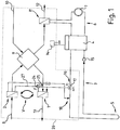
- ein schematisches Blockschaltbild einer ersten Wärmepumpenheizvorrichtung gemäß der Erfindung,
Figur 2- ein schematisches Blockschaltbild einer zweiten Wärmepumpenheizvorrichtung gemäß der Erfindung,
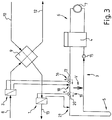
Figur 3- ein schematisches Blockschaltbild einer dritten Wärmepumpenheizvorrichtung gemäß der Erfindung,
Figur 4- ein schematisches Blockschaltbild einer vierten Wärmepumpenheizvorrichtung gemäß der Erfindung,
Figur 5- ein schematisches Blockschaltbild einer fünften Wärmepumpenheizvorrichtung gemäß der Erfindung und
Figur 6- ein schematisches Blockschaltbild einer sechsten Wärmepumpenheizvorrichtung gemäß der Erfindung.
- FIG. 1
- 1 is a schematic block diagram of a first heat pump heating device according to the invention,
- FIG. 2
- a schematic block diagram of a second heat pump heating device according to the invention,
- FIG. 3
- a schematic block diagram of a third heat pump heating device according to the invention,
- FIG. 4
- 3 is a schematic block diagram of a fourth heat pump heating device according to the invention,
- FIG. 5
- a schematic block diagram of a fifth heat pump heating device according to the invention and
- FIG. 6
- a schematic block diagram of a sixth heat pump heating device according to the invention.
Die in den Figuren sind unterschiedliche Ausführungsbeispiele aufgeführt, die sich im Wesentlichen auf unterschiedliche Anordnungen bzw. Integrations- und Verschaltungsmöglichkeiten von einem ersten Luft-Wärmetauscher 1 und einen zweiten Luft-Wärmetauscher 2 in einen von einer Pumpe 15 angetriebenen Wärmepumpenkreislauf 3 gemäß der Erfindung beziehen. Hierbei bezeichnen gleiche Bezugszeichen im Wesentlichen gleiche bzw. vergleichbare Komponenten bzw. Merkmale.In the figures, different embodiments are listed, which relate essentially to different arrangements or integration and Verschaltungsmöglichkeiten of a first air heat exchanger 1 and a second
Der Wärmepumpenkreislauf 3 umfasst zumindest eine Wärmepumpe 4 und einen Wärmequellen-Wärmetauscher 5, der vorzugsweise als eine Erdsonde 5 bzw. ein Erdkollektor 5, als sog. Eisspeicher 5, als sog. Saisonalspeicher 5 oder dergleichen ausgebildet ist. Vorzugsweise ist eine Stromversorgung 14 und/oder Steuerung 14 bzw. Platine 14 der Wärmepumpe 4 zugeordnet, was nicht in allen Figuren schematisch dargestellt ist.The
Die Wärmepumpe 4 ist in bekannter Weise aufgebaut und umfasst im Wesentlichen (nicht näher dargestellt) einen geschlossenen Kreislauf v.a. mit einem Kondensator, einem Verdampfer und einem Expansionsventil sowie einer Pumpe, wobei der Verdampfer als Wärmetauscher eine Komponente des Wärmepumpenkreislaufs 3 ist, d.h. in diesem integriert/eingebunden und somit einerseits von einem Wärmepumpenfluid und andererseits von einem Wärmequellenfluid durchflossen ist. Der Kondensator ist entsprechend in bekannter Weise als Wärmetauscher in einen Heizkreislauf 6 eingebunden bzw. integriert. Der Heizkreislauf 6 umfasst zudem einen Warmwasserboiler 7 bzw. Heizkörper 7, insb. sog. Flächenheizkörper 7, oder dergleichen und einen optional vorzusehenden dritten Luft-Wärmetauscher 11 (vgl. Varianten gemäß
Der zweite Luft-Wärmetauscher 2 ist als sog. Außenluft-Wärmetauscher 2 ausgebildet und von einem ersten Luftstrom durchströmt, der als sog. Außenluft 8 bezeichnet wird, d.h. von außen eingesaugt bzw. der atmosphärischen Luft entstammt. Dieser Luft-Wärmetauscher 2 ist in Strömungsrichtung der Außenluft 8 vor einem sog. Kreuzwärmetauscher 9 bzw. Plattenwärmetauscher 9 angeordnet. Der Kreuzwärmetauscher 9 ist zur Wärmerückgewinnung ausgebildet, wobei dieser zudem von einem zweiten, wärmeren, vom Gebäudeinneren bzw. von innen stammenden/eingesaugten Luftstrom durchströmt wird, der als sog. Innenluft 10 bezeichnet wird.The second
Der erste Luftstrom wird nach dem Kreuzwärmetauscher 9 beim in das Gebäude einströmen auch als sog. Zuluft 12 bezeichnet, wobei dieser vor dem Einströmen in einen Gebäudeinnenraum optional den dritten Luft-Wärmetauscher 11 durchströmt (siehe oben). Der zweite Luftstrom wird nach dem Kreuzwärmetauscher 9 beim aus dem Gebäude ausströmen auch als sog. Fortluft 13 bezeichnet, wobei dieser vor dem Ausströmen aus dem Gebäude bzw. in die Atmosphäre den ersten Luft-Wärmetauscher 1 durchströmt (siehe oben).The first air flow after the
Bei der bevorzugten Variante der Erfindung gemäß
Die Varianten gemäß den
Es können gemäß den anderen Varianten der Erfindung gemäß den
Darüber hinaus ist von Vorteil, mit Hilfe eines weiteren Stellglieds 24 bzw. Ventils 24 bzw. Abzweigstelle 24 eine Überbrückung 25 bzw. ein Bypass 25 für den ersten im Teilkreis angeordneten Luft-Wärmetauscher 1, 2 (vgl.
Das in den Figuren dargestellte V mit dem oder den zugeordneten Pfeilen stellt jeweils eine weitere, ansonsten nicht näher dargestellte Variante V der jeweiligen Figur dar, bei dem die entspr. Komponenten, z.B. Luft-Wärmetauscher 1, 2 gemäß
Gemäß der Variante der
Grundsätzlich können diverse Sensoren, wie Temperatursensoren und/oder Durchflusssensoren oder dergleichen im System von großem Vorteil für die Steuerung/Regelung und die unterschiedlichste Betriebsweisen sein.In principle, various sensors, such as temperature sensors and / or flow sensors or the like in the system can be of great advantage for the control / regulation and the most varied modes of operation.
- 11
- Luft-WärmetauscherAir heat exchanger
- 22
- Luft-WärmetauscherAir heat exchanger
- 33
- Wärmepumpen-KreislaufHeat pump circuit
- 44
- Wärmepumpeheat pump
- 55
- Erd-WärmetauscherEarth heat exchanger
- 66
- Heizkreislaufheating circuit
- 77
- Boiler/HeizkörperBoiler / radiator
- 88th
- Außenluftoutside air
- 99
- Kreuz-WärmetauscherCross heat exchanger
- 1010
- Innenluftindoor air
- 1111
- Luft-WärmetauscherAir heat exchanger
- 1212
- Zuluftsupply air
- 1313
- FortluftExhaust air
- 1414
- Steuerungcontrol
- 1515
- Pumpepump
- 1616
- Abzweigstellebranching point
- 1717
- VentilValve
- 1818
- Abzweigstellebranching point
- 1919
- Abzweigstellebranching point
- 2020
- VentilValve
- 2121
- Abzweigstellebranching point
- 2222
- Erd-WärmetauscherEarth heat exchanger
- 2323
- Pumpepump
- 2424
- VentilValve
- 2525
- Bypassbypass
- 2626
- Baueinheitunit
- 2727
- Verbindungconnection
- VV
- Variantevariant
Claims (10)
Priority Applications (3)
| Application Number | Priority Date | Filing Date | Title |
|---|---|---|---|
| EP18174262.8A EP3572732A1 (en) | 2018-05-25 | 2018-05-25 | Heat pump heating device for heating of a building or an industrial water storage device |
| DK19176158.4T DK3572733T3 (en) | 2018-05-25 | 2019-05-23 | Heat pump heating device for heating a building or a domestic water tank |
| EP19176158.4A EP3572733B1 (en) | 2018-05-25 | 2019-05-23 | Heat pump heating device for heating of a building or an industrial water storage device |
Applications Claiming Priority (1)
| Application Number | Priority Date | Filing Date | Title |
|---|---|---|---|
| EP18174262.8A EP3572732A1 (en) | 2018-05-25 | 2018-05-25 | Heat pump heating device for heating of a building or an industrial water storage device |
Publications (1)
| Publication Number | Publication Date |
|---|---|
| EP3572732A1 true EP3572732A1 (en) | 2019-11-27 |
Family
ID=62386095
Family Applications (2)
| Application Number | Title | Priority Date | Filing Date |
|---|---|---|---|
| EP18174262.8A Withdrawn EP3572732A1 (en) | 2018-05-25 | 2018-05-25 | Heat pump heating device for heating of a building or an industrial water storage device |
| EP19176158.4A Active EP3572733B1 (en) | 2018-05-25 | 2019-05-23 | Heat pump heating device for heating of a building or an industrial water storage device |
Family Applications After (1)
| Application Number | Title | Priority Date | Filing Date |
|---|---|---|---|
| EP19176158.4A Active EP3572733B1 (en) | 2018-05-25 | 2019-05-23 | Heat pump heating device for heating of a building or an industrial water storage device |
Country Status (2)
| Country | Link |
|---|---|
| EP (2) | EP3572732A1 (en) |
| DK (1) | DK3572733T3 (en) |
Cited By (1)
| Publication number | Priority date | Publication date | Assignee | Title |
|---|---|---|---|---|
| DE102020115277A1 (en) | 2020-06-09 | 2021-12-09 | Stiebel Eltron Gmbh & Co. Kg | Method and device for power control passive cooling |
Citations (5)
| Publication number | Priority date | Publication date | Assignee | Title |
|---|---|---|---|---|
| DE10323287A1 (en) * | 2003-02-14 | 2004-09-02 | Hombücher, Heinz-Dieter | Method and device for energy recovery |
| DE102004039569A1 (en) | 2003-08-20 | 2005-03-17 | Vaillant Gmbh | Device for raising temperature of salt in heat source circuit of heat pump directs salt stream through salt-air heat exchanger through which fresh or waste air of room is guided |
| EP1731846A1 (en) * | 2005-06-09 | 2006-12-13 | Drexel und Weiss Energieeffiziente Haustechniksysteme GmbH | Ventilation and heating arrangement for buildings |
| DE112014000527T5 (en) * | 2013-01-23 | 2015-10-15 | Denso Corporation | heating system |
| DE112014001194T5 (en) * | 2013-03-08 | 2015-11-19 | Denso Corporation | Heating and hot water supply device |
-
2018
- 2018-05-25 EP EP18174262.8A patent/EP3572732A1/en not_active Withdrawn
-
2019
- 2019-05-23 EP EP19176158.4A patent/EP3572733B1/en active Active
- 2019-05-23 DK DK19176158.4T patent/DK3572733T3/en active
Patent Citations (5)
| Publication number | Priority date | Publication date | Assignee | Title |
|---|---|---|---|---|
| DE10323287A1 (en) * | 2003-02-14 | 2004-09-02 | Hombücher, Heinz-Dieter | Method and device for energy recovery |
| DE102004039569A1 (en) | 2003-08-20 | 2005-03-17 | Vaillant Gmbh | Device for raising temperature of salt in heat source circuit of heat pump directs salt stream through salt-air heat exchanger through which fresh or waste air of room is guided |
| EP1731846A1 (en) * | 2005-06-09 | 2006-12-13 | Drexel und Weiss Energieeffiziente Haustechniksysteme GmbH | Ventilation and heating arrangement for buildings |
| DE112014000527T5 (en) * | 2013-01-23 | 2015-10-15 | Denso Corporation | heating system |
| DE112014001194T5 (en) * | 2013-03-08 | 2015-11-19 | Denso Corporation | Heating and hot water supply device |
Cited By (1)
| Publication number | Priority date | Publication date | Assignee | Title |
|---|---|---|---|---|
| DE102020115277A1 (en) | 2020-06-09 | 2021-12-09 | Stiebel Eltron Gmbh & Co. Kg | Method and device for power control passive cooling |
Also Published As
| Publication number | Publication date |
|---|---|
| EP3572733B1 (en) | 2021-01-27 |
| DK3572733T3 (en) | 2021-04-19 |
| EP3572733A1 (en) | 2019-11-27 |
Similar Documents
| Publication | Publication Date | Title |
|---|---|---|
| EP1731846B1 (en) | Ventilation and heating arrangement for buildings | |
| EP3447403B1 (en) | Operating method for heat generation installations, air/liquid heat exchanger unit and heat generation installation | |
| DE102011001273A1 (en) | Storage tank for an energy storage system and energy storage system with such storage tanks | |
| DE202009006988U1 (en) | Hot water supply system with a hot water tank | |
| DE10118572B4 (en) | Heat supply system | |
| EP3607249B1 (en) | Heat pump system | |
| DE19851889C2 (en) | Method for operating an air / water heat pump with energy recycling and device for carrying out the method | |
| EP2602558A2 (en) | Apparatus and method for supplying heat to a building | |
| EP3572733B1 (en) | Heat pump heating device for heating of a building or an industrial water storage device | |
| DE10106975A1 (en) | Air-water heat pump with heat recovery, supply air preheating and cooling | |
| DE102017006550A1 (en) | HVACC system for heating, ventilation, air conditioning and central refrigerant supply for a building | |
| WO2024002855A1 (en) | Dual connection system for heat pumps and geothermal collectors | |
| DE202013005661U1 (en) | Building ventilation system with solar-based fresh air heating | |
| WO2016109861A2 (en) | Method for the regeneration of the primary energy store of a brine water heat pump | |
| EP0811809A2 (en) | Method for operating a heat pump | |
| EP2247898B1 (en) | Method for optimizing thermal energy current guidance | |
| EP2765360A2 (en) | Heat pump device, use of a pump with heatable pump chamber in a heat pump device and method for operating a heat pump device | |
| DE202019103149U1 (en) | Device for heating a fluid medium | |
| EP2942570B1 (en) | Geothermal heating installation | |
| EP1376020B2 (en) | Method and Device for tempering outdoor air used for rooms ventilation | |
| DE2723503A1 (en) | Insulated building air conditioning plant - has auxiliary heating system for water and air heating | |
| DE102021130845A1 (en) | System for air conditioning a building. | |
| DE102007016212A1 (en) | Heating and/or cooling system i.e. variable refrigerant flow system, operating method, involves delivering heat and/or cold from geothermal energy system in refrigerant pipes over heat exchanger that acts as evaporator or condenser | |
| DE102007037474A1 (en) | Heating/cooling system i.e. variable refrigerant flow system, operating method for interior space, involves transferring cold from weather-independent energy sources over heat exchanger into heat | |
| DE102016118516A1 (en) | Device for storing thermal energy and system with the device |
Legal Events
| Date | Code | Title | Description |
|---|---|---|---|
| PUAI | Public reference made under article 153(3) epc to a published international application that has entered the european phase |
Free format text: ORIGINAL CODE: 0009012 |
|
| AK | Designated contracting states |
Kind code of ref document: A1 Designated state(s): AL AT BE BG CH CY CZ DE DK EE ES FI FR GB GR HR HU IE IS IT LI LT LU LV MC MK MT NL NO PL PT RO RS SE SI SK SM TR |
|
| AX | Request for extension of the european patent |
Extension state: BA ME |
|
| STAA | Information on the status of an ep patent application or granted ep patent |
Free format text: STATUS: THE APPLICATION IS DEEMED TO BE WITHDRAWN |
|
| 18D | Application deemed to be withdrawn |
Effective date: 20200603 |
|
| P01 | Opt-out of the competence of the unified patent court (upc) registered |
Effective date: 20230525 |