JP2014170676A - Lighting device - Google Patents
Lighting device Download PDFInfo
- Publication number
- JP2014170676A JP2014170676A JP2013041988A JP2013041988A JP2014170676A JP 2014170676 A JP2014170676 A JP 2014170676A JP 2013041988 A JP2013041988 A JP 2013041988A JP 2013041988 A JP2013041988 A JP 2013041988A JP 2014170676 A JP2014170676 A JP 2014170676A
- Authority
- JP
- Japan
- Prior art keywords
- case
- light emitting
- base
- heat sink
- lighting device
- Prior art date
- Legal status (The legal status is an assumption and is not a legal conclusion. Google has not performed a legal analysis and makes no representation as to the accuracy of the status listed.)
- Pending
Links
- 239000004065 semiconductor Substances 0.000 claims description 30
- 239000000758 substrate Substances 0.000 claims description 11
- 238000005286 illumination Methods 0.000 claims description 10
- 239000004035 construction material Substances 0.000 claims description 9
- 230000002093 peripheral effect Effects 0.000 claims description 5
- 230000000149 penetrating effect Effects 0.000 claims description 3
- 230000005855 radiation Effects 0.000 abstract description 26
- 239000000463 material Substances 0.000 description 9
- 238000003780 insertion Methods 0.000 description 7
- 230000037431 insertion Effects 0.000 description 7
- 239000011347 resin Substances 0.000 description 6
- 229920005989 resin Polymers 0.000 description 6
- OAICVXFJPJFONN-UHFFFAOYSA-N Phosphorus Chemical compound [P] OAICVXFJPJFONN-UHFFFAOYSA-N 0.000 description 5
- NJPPVKZQTLUDBO-UHFFFAOYSA-N novaluron Chemical compound C1=C(Cl)C(OC(F)(F)C(OC(F)(F)F)F)=CC=C1NC(=O)NC(=O)C1=C(F)C=CC=C1F NJPPVKZQTLUDBO-UHFFFAOYSA-N 0.000 description 5
- 229910052782 aluminium Inorganic materials 0.000 description 4
- XAGFODPZIPBFFR-UHFFFAOYSA-N aluminium Chemical compound [Al] XAGFODPZIPBFFR-UHFFFAOYSA-N 0.000 description 4
- 230000017525 heat dissipation Effects 0.000 description 4
- 230000020169 heat generation Effects 0.000 description 4
- 229910052751 metal Inorganic materials 0.000 description 4
- 239000002184 metal Substances 0.000 description 4
- 238000010586 diagram Methods 0.000 description 3
- 238000012423 maintenance Methods 0.000 description 3
- 238000000034 method Methods 0.000 description 3
- 238000012546 transfer Methods 0.000 description 3
- OKTJSMMVPCPJKN-UHFFFAOYSA-N Carbon Chemical compound [C] OKTJSMMVPCPJKN-UHFFFAOYSA-N 0.000 description 2
- FYYHWMGAXLPEAU-UHFFFAOYSA-N Magnesium Chemical compound [Mg] FYYHWMGAXLPEAU-UHFFFAOYSA-N 0.000 description 2
- 239000000853 adhesive Substances 0.000 description 2
- 230000001070 adhesive effect Effects 0.000 description 2
- 229910052799 carbon Inorganic materials 0.000 description 2
- 239000004020 conductor Substances 0.000 description 2
- 230000000694 effects Effects 0.000 description 2
- 229910052749 magnesium Inorganic materials 0.000 description 2
- 239000011777 magnesium Substances 0.000 description 2
- 230000000191 radiation effect Effects 0.000 description 2
- 229920000178 Acrylic resin Polymers 0.000 description 1
- 239000004925 Acrylic resin Substances 0.000 description 1
- 206010037660 Pyrexia Diseases 0.000 description 1
- PNEYBMLMFCGWSK-UHFFFAOYSA-N aluminium oxide Inorganic materials [O-2].[O-2].[O-2].[Al+3].[Al+3] PNEYBMLMFCGWSK-UHFFFAOYSA-N 0.000 description 1
- 239000011324 bead Substances 0.000 description 1
- 238000005452 bending Methods 0.000 description 1
- 238000001816 cooling Methods 0.000 description 1
- 229920003020 cross-linked polyethylene Polymers 0.000 description 1
- 239000004703 cross-linked polyethylene Substances 0.000 description 1
- 230000002349 favourable effect Effects 0.000 description 1
- 239000011521 glass Substances 0.000 description 1
- 239000004519 grease Substances 0.000 description 1
- 238000001746 injection moulding Methods 0.000 description 1
- 239000007769 metal material Substances 0.000 description 1
- 238000012986 modification Methods 0.000 description 1
- 230000004048 modification Effects 0.000 description 1
- 229920000515 polycarbonate Polymers 0.000 description 1
- 239000004417 polycarbonate Substances 0.000 description 1
- -1 polyethylene terephthalate Polymers 0.000 description 1
- 229920000139 polyethylene terephthalate Polymers 0.000 description 1
- 239000005020 polyethylene terephthalate Substances 0.000 description 1
- 229920001296 polysiloxane Polymers 0.000 description 1
- 238000003825 pressing Methods 0.000 description 1
- 230000002265 prevention Effects 0.000 description 1
- 238000004080 punching Methods 0.000 description 1
- 238000007789 sealing Methods 0.000 description 1
- 229920002379 silicone rubber Polymers 0.000 description 1
- 239000004945 silicone rubber Substances 0.000 description 1
- 229910001220 stainless steel Inorganic materials 0.000 description 1
- 239000010935 stainless steel Substances 0.000 description 1
- 238000009423 ventilation Methods 0.000 description 1
Images


Abstract
Description
本発明はLED(Light Emitting Device)等の半導体発光素子を照明用光源とする照明装置に関する。 The present invention relates to an illumination device using a semiconductor light emitting element such as an LED (Light Emitting Device) as a light source for illumination.
近年、LED等の半導体発光素子を光源とする照明装置が普及している。
図8は特許文献1に記載された、従来の吊下型(ペンダント型)の照明装置1xの構成例を示す、外観構成図である。照明装置1xは、ケーブル2xと、ケーブル2xの先端に取り付けられたLED3xと、LED3xの出射方向前方に配された反射部4xと、LED3x及び反射部4xを覆うように配されたケース(シェード)5xとを有する。ケース5xの内面には蛍光体層6xが塗布される。照明装置1xの駆動時には、LED3xからの出射光が直接、または反射部4xで反射された後に蛍光体層6xに照射される(図中の矢印)。その後、LED3xからの光は蛍光体層6xで波長変換され、外部に照明光として出射される。
2. Description of the Related Art In recent years, lighting devices using semiconductor light emitting elements such as LEDs as light sources have become widespread.
FIG. 8 is an external configuration diagram showing a configuration example of a conventional hanging type (pendant type)
半導体発光素子を照明用光源とする照明装置では、半導体発光素子の駆動により生じた熱を効率よく放熱させることが長寿命の観点から望ましい。このため、半導体発光素子と熱結合するようにヒートシンクを配し、ヒートシンクをケースで覆った構成が開発されている。ヒートシンクの熱は、例えばケースを介して空気中に放熱される。
一方、ヒートシンクとケースとを有する照明装置では、駆動中または駆動直後の高温状態の照明装置のケースにユーザやメンテナンス者が触れる可能性があることを考慮して、発熱時の安全対策を予め図っておく必要がある。このように照明装置では、良好な放熱特性を得るとともに、発熱時に対する安全性をも得ることが要求される。
In an illumination device using a semiconductor light emitting element as a light source for illumination, it is desirable from the viewpoint of long life to efficiently dissipate heat generated by driving the semiconductor light emitting element. For this reason, a configuration in which a heat sink is arranged so as to be thermally coupled to the semiconductor light emitting element and the heat sink is covered with a case has been developed. The heat of the heat sink is dissipated into the air through the case, for example.
On the other hand, in the case of a lighting device having a heat sink and a case, safety measures are taken in advance when heat is generated in consideration of the possibility that the user or maintenance personnel may touch the case of the lighting device in a high temperature state during or immediately after driving. It is necessary to keep. As described above, the lighting device is required to obtain good heat dissipation characteristics and also to have safety against heat generation.
本発明は以上の課題に鑑みてなされたものであって、良好な放熱特性とともに、発熱時でも高い安全性を発揮することが可能な照明装置の提供を目的とする。 This invention is made | formed in view of the above subject, Comprising: It aims at provision of the illuminating device which can exhibit high safety | security also at the time of heat_generation | fever with a favorable heat dissipation characteristic.
上記課題を解決するため、本発明の一態様に係る照明装置は、半導体発光素子と、一方の面上に前記半導体発光素子が配された板状の基台と、前記基台の他方の面上に、前記基台を介して前記半導体発光素子と対向する状態で配されたヒートシンクと、前記ヒートシンクを囲む状態で、前記基台の外縁部と連結されたケースとを備え、前記ケースと前記基台とには前記ケースの内外を連通する通気孔がそれぞれ存在し、前記ヒートシンクと前記ケースとが離間している構成とする。 In order to solve the above problems, a lighting device according to one embodiment of the present invention includes a semiconductor light-emitting element, a plate-like base on which the semiconductor light-emitting element is arranged on one surface, and the other surface of the base A heat sink disposed in a state of facing the semiconductor light emitting element via the base, and a case connected to an outer edge of the base in a state of surrounding the heat sink, the case and the The base has a vent hole communicating with the inside and outside of the case, and the heat sink and the case are separated from each other.
本発明の別の態様では、前記ヒートシンクは、少なくとも前記基台の厚み方向に沿って前記半導体発光素子と重なる位置に配されている構成とすることもできる。
本発明の別の態様では、前記ヒートシンクは、前記基台の前記他方の面に立設された複数のフィンを有し、前記ケースの通気孔は、前記基台のいずれかの面を平面視する際、少なくともいずれかの前記フィンと重なる位置に存在する構成とすることもできる。
In another aspect of the present invention, the heat sink may be arranged at a position overlapping the semiconductor light emitting element along at least the thickness direction of the base.
In another aspect of the present invention, the heat sink has a plurality of fins erected on the other surface of the base, and the vent hole of the case is a plan view of any surface of the base. When doing, it can also be set as the structure which exists in the position which overlaps at least one of the said fins.
本発明の別の態様では、前記複数のフィンは、前記基台の前記他方の面上に存在する基準位置を中心とする複数の円周上に沿って配列されており、前記ケースは錐台状であって、前記基準位置に近い円周上のフィンの高さが、前記基準位置より遠い円周上のフィンの高さよりも高い構成とすることもできる。
本発明の別の態様では、前記基台は円盤状であり、前記ケースは円錐台状であって、前記半導体発光素子は前記基台の一方の面の中央領域に配され、前記基台の通気孔は、前記中央領域を取り囲む周辺領域において複数存在する構成とすることもできる。
In another aspect of the present invention, the plurality of fins are arranged along a plurality of circumferences centering on a reference position existing on the other surface of the base, and the case includes a frustum The height of the fin on the circumference close to the reference position may be higher than the height of the fin on the circumference far from the reference position.
In another aspect of the present invention, the base has a disk shape, the case has a truncated cone shape, the semiconductor light emitting element is disposed in a central region of one surface of the base, A plurality of vent holes may be provided in a peripheral region surrounding the central region.
本発明の別の態様では、前記半導体発光素子はLEDであり、基板の表面に前記半導体発光素子を複数実装してなるLEDモジュールをさらに備え、前記各半導体発光素子が前記基板を介して前記基台と熱結合されている構成とすることもできる。
本発明の別の態様では、複数の前記LEDモジュールが、前記基準位置を中心とする円周上に沿って配列されている構成とすることもできる。
In another aspect of the present invention, the semiconductor light emitting element is an LED, and further includes an LED module in which a plurality of the semiconductor light emitting elements are mounted on a surface of a substrate, and each of the semiconductor light emitting elements is disposed on the substrate via the substrate. It can also be set as the structure thermally coupled with the stand.
In another aspect of the present invention, a plurality of the LED modules may be arranged along a circumference centered on the reference position.
本発明の別の態様では、一端が前記基台と連結され且つ前記ケースを貫通するように配されたパイプと、前記パイプの他端に連結され且つ造営材に対して取り付けられる取付部とを有する構成とすることもできる。 In another aspect of the present invention, a pipe having one end connected to the base and penetrating the case, and a mounting portion connected to the other end of the pipe and attached to the construction material. It can also be set as the structure which has.
本発明の一態様に係る照明装置では、ヒートシンクが基台を介して半導体発光素子と対向する状態で配設されているので、半導体発光素子で生じた熱がヒートシンクに伝熱される。一方、基台とケースとにそれぞれ設けた通気孔を介し、ケースの内外に空気を流通できるので、ケース内のヒートシンクの熱が空気中に放熱され、熱交換後の空気が外部に放出される。よって、半導体発光素子の良好な放熱特性を期待することが可能である。 In the lighting device according to one embodiment of the present invention, since the heat sink is disposed in a state of facing the semiconductor light emitting element through the base, heat generated in the semiconductor light emitting element is transferred to the heat sink. On the other hand, air can flow in and out of the case through the air holes provided in the base and the case, so the heat of the heat sink in the case is dissipated into the air, and the air after heat exchange is released to the outside . Therefore, it is possible to expect good heat dissipation characteristics of the semiconductor light emitting device.
また、ケースは基台の外縁部と連結されるとともに、ヒートシンクとケースととが離間されている。これにより、ケースと基台とが連結されていても、半導体発光素子の駆動により生じた熱は、基台とヒートシンクとのいずれを介してもケースに伝熱しにくい。よって、半導体発光素子の駆動により生じた熱によって、ケースが過熱されるのを防止できる。従って、駆動中または駆動直後の照明装置にユーザやメンテナンス者がケースに触れる場合を考慮して、発熱時の安全対策を予め講じることが可能である。 The case is connected to the outer edge of the base, and the heat sink and the case are separated from each other. Thereby, even if the case and the base are connected, the heat generated by driving the semiconductor light emitting element is difficult to transfer to the case through either the base or the heat sink. Therefore, it is possible to prevent the case from being overheated by heat generated by driving the semiconductor light emitting element. Therefore, it is possible to take safety measures in advance when heat is generated in consideration of a case where a user or a maintenance person touches the case during or immediately after driving.
結果として、良好な放熱特性とともに、発熱時でも高い安全性を発揮することが可能な照明装置を提供できる。 As a result, it is possible to provide an illumination device that can exhibit high heat dissipation characteristics and high safety even during heat generation.
以下、本発明の実施の形態について説明する。
[実施の形態]
以下、実施の形態にかかる照明装置について、図面を参照しながら説明する。
(照明装置1の全体構成)
図1〜4、図6、図7において、矢印Yで示す方向が後方、その反対方向が前方である。照明装置1において光は主に前方に出射される。
Embodiments of the present invention will be described below.
[Embodiment]
Hereinafter, an illumination device according to an embodiment will be described with reference to the drawings.
(Overall configuration of lighting device 1)
1-4, FIG. 6, and FIG. 7, the direction shown by the arrow Y is the rear, and the opposite direction is the front. In the
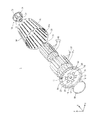
図1〜4に示すように、照明装置1は、モジュールプレート10、モジュールプレート10の前面に配置された複数の発光モジュール20、モジュールプレート10の中央部から後方に伸長する支持パイプ30を備えている。
また照明装置1においては、モジュールプレート10の後面に、内ヒートシンク40、及び外ヒートシンク50が取り付けられている。
As illustrated in FIGS. 1 to 4, the
In the
内ヒートシンク40は複数の放熱フィン42を有し、外ヒートシンク50も複数の放熱フィン52を有している。支持パイプ30の周囲を取り囲むように、複数の放熱フィン42、52はモジュールプレート10から後方に伸長して配設される。
さらに照明装置1において、モジュールプレート10の外縁から後方に伸長し、内ヒートシンク40、外ヒートシンク50を取り囲むケース60が装着されている。
The
Further, in the
支持パイプ30の後端部32には、支持パイプ30を、造営材(体育館、工場、倉庫の天井など)に取り付けるための部材である取付部70が装着されている。
モジュールプレート10の前面には、複数の発光モジュール20を覆うカバー80が装着されている。
支持パイプ30の内部には、外部に設置された電源装置から複数の発光モジュール20に電力を供給するための配線90a、90b(図5(a)参照)が挿通されている。
An
A
この照明装置1は造営材に取り付けられ、HIDランプ代替の照明装置として用いられる。
照明装置1の各構成要素について以下に説明する。
(モジュールプレート10)
モジュールプレート10は円盤状の部材(基台)である。モジュールプレート10の材料としては、高い熱伝導性材料、例えばアルミニウムやマグネシウムなどの金属材料が挙げられる。モジュールプレート10の中央部には支持パイプ30の前端部31を填め込むための嵌合孔11が開設されている。
This
Each component of the
(Module plate 10)
The
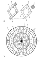
モジュールプレート10の一方の面(前面)の中央領域には、嵌合孔11の周囲に複数(6個)の発光モジュール20を取り付けるためのモジュール取付領域12が確保される。モジュール取付領域12を取り囲む周辺領域には、複数の通気孔13が周方向に沿って円環状に列設されている。
各通気孔13は、モジュールプレート10の板材を打ち抜き加工して形成される。各通気孔13を一定間隔毎に形成することで、隣接する通気孔13の間にブリッジ14が形成されている。
In a central region of one surface (front surface) of the
Each
モジュールプレート10の直径は例えば260mm、板厚は例えば1.0〜5.0mmである。
(発光モジュール20)
モジュール取付領域12には複数(6個)の発光モジュール20が環状に配置されている。各発光モジュール20は図5(a)に示すように、嵌合孔11の周囲に60°ずつ角度を置いて配されている。
The diameter of the
(Light Emitting Module 20)
A plurality (six) of
各発光モジュール20はLEDモジュールであり、図5(b)に示すように、基板21と、基板21上に形成された発光部22とを有している。
基板21は、例えばアルミナあるいはアルミ材料で形成され、その表面には発光部22に電力供給するための配線パターン(不図示)が形成されている。
発光部22は、基板21の表面に実装された複数個(一例として132個)のCOB(Chip on Board)タイプのLED23と、そのLED23を覆うように配された蛍光体を含む封止層によって構成されている。LED23は半導体発光素子の一例である。発光部22は、LED23から放射される青色光の一部を蛍光体で相対的に長い波長の光に変換し、且つ青色光と混色することで白色光を放射する。
Each
The
The
各発光モジュール20は、モジュールプレート10のモジュール取付領域12に熱結合された状態で取り付けられている。
具体的には図5(a)に示すように、各発光モジュール20は速結端子24a、24bを有するソケット24で覆われている。ソケット24がモジュールプレート10にねじ止めされることで、発光モジュール20はモジュールプレート10の前面に押し付けられた状態で固定されている。これにより発光モジュール20から発生する熱は、モジュールプレート10に効率よく伝熱される。ソケット24の速結端子24a、24bは、発光モジュール20のアノード端子25a及びカソード端子25bに接続される。
Each
Specifically, as shown in FIG. 5A, each light emitting
(支持パイプ30)
支持パイプ30は、伝熱性の良好な材料で形成された直管である。支持パイプ30の材料としては、例えば、ステンレスなどの金属、もしくは伝熱性の良好な樹脂(樹脂にカーボンなどを混合してなる熱伝導性樹脂)が挙げられる。
支持パイプ30の前端部31は、嵌合孔11に填め込まれてモジュールプレート10に接合される。具体的には、支持パイプ30の前端部31を、モジュールプレート10の嵌合孔11に差し込んで、前端部31を嵌合孔11の縁にかしめ加工することによって接合されている。
(Support pipe 30)
The
The
一方、支持パイプ30の後端部32は、取付部70の差込口72に差し込まれた状態で、取付部70に接合されている。
このように支持パイプ30は、モジュールプレート10を支持する機能を有し、またモジュールプレート10から取付部70に熱を良好に伝導させる通路となっている。さらに、支持パイプ30の内部の中空部分は、配線90a、90bが挿通する通路となっている。
On the other hand, the
As described above, the
支持パイプ30の長さは、ケース60の高さと同程度、もしくはそれ以上であって、例えば30cm〜40cm程度である。
支持パイプ30の外径及び肉厚は大きいほど強度が高まる。またこの外径及び肉厚が大きいほど、断面積が大きくなるので、伝熱効率も高まり、モジュールプレート10の温度を低減できる点で好ましいが、重量が大きくなるので、これらの点を考慮して適当な範囲に定めればよい。
The length of the
The strength increases as the outer diameter and thickness of the
支持パイプ30が金属で形成されている場合、例えば支持パイプ30の外径は27mm、肉厚は1mm〜3mm程度である。
(内ヒートシンク40、外ヒートシンク50)
内ヒートシンク40は、モジュールプレート10の他方の面(背面)に立設された複数のフィン42を有する。同様に外ヒートシンク50も、モジュールプレート10の他方の面(背面)に立設された複数のフィン52を有する。内ヒートシンク40、外ヒートシンク50は、その少なくとも一方がモジュールプレート10を介してLED23と対向する状態で配される。
When the
(
The
具体的に内ヒートシンク40は、支持パイプ30の周囲においてモジュールプレート10の後面に接合される円環状の支持部41と、支持部41の外周部から後方に伸長する複数の短冊状の放熱フィン42とで構成されている。外ヒートシンク50は、支持部41の周りにおいてモジュールプレート10の後面に接合される円環状の支持部51と、支持部51の外周部から後方に伸長する複数の短冊状の放熱フィン52とで構成されている。支持部41及び支持部51は、モジュールプレート10にリベットあるいはねじなどで締結されている。
Specifically, the
複数の放熱フィン42は、支持パイプ30を取り囲んで支持パイプ30と平行に伸長し、複数の放熱フィン52は、その外側を取り囲んで、支持パイプ30と平行に伸長している。すなわち、各放熱フィン42、52は図4に示すように、モジュールプレート10のケース60との対向面上に存在する基準位置(支持パイプ30の軸心が通る位置)の周囲を取り囲むように配列される。具体的に放熱フィン42、52は、基準位置を中心とする複数(ここでは2つ)の円周上に沿って配列される。
The plurality of radiating
内ヒートシンク40、外ヒートシンク50は、モジュールプレート10と同様、熱伝導率の高い材料(例えばアルミニウム等の金属)で形成されている。
各放熱フィン42、52は、Y方向から平面視するとき、支持パイプ30の中心軸からの径方向に対して一定の角度(例えば45°)で傾斜している。
放熱フィン42、52の高さは適切な放熱特性を得るために十分な高さとする。ケース60の形状に合わせ、基準位置に近い円周上にある放熱フィン42の高さが、基準位置より遠い円周上にある放熱フィン52の高さよりも高くなるように調整される。ここで照明装置1の特徴として、図6の部分断面図に示すように、放熱フィン52とケース60との間にはある程度の最短距離Dが設けられる。これにより外ヒートシンク50とケース60とは互いに接触が回避されている。
As with the
Each of the
The height of the
最短距離Dは適宜調節することができる。最短距離Dを短くすると、内ヒートシンク40及び外ヒートシンク50の輻射熱をケース60に伝熱し、半導体発光素子の放熱効果を高めることができる。反対に最短距離Dを長くすると、内ヒートシンク40及び外ヒートシンク50の輻射熱がケース60に及びににくくすることができる。照明装置1では、一例として最短距離Dを10mmとしている。
The shortest distance D can be adjusted as appropriate. When the shortest distance D is shortened, the radiant heat of the
(ケース60)
図1〜4に示すように、ケース60は内ヒートシンク40及び外ヒートシンク50を囲む状態で、モジュールプレート10の外縁部と連結される。具体的にケース60は、円錐台状の外観を有し、モジュールプレート10の外縁から後方に伸長する円筒形状の筒状部61と、この筒状部61の後部を塞ぐ天板部62とを有し、筒状部61は放熱フィン52の外側を取り囲んでいる。筒状部61の前端部61aは開口し、そこにモジュールプレート10が装着される。
(Case 60)
As shown in FIGS. 1 to 4, the
筒状部61とモジュールプレート10との固定は、筒状部61の前端部61aをモジュールプレート10の外縁部15にかしめることによってなされている。
天板部62の中央には、支持パイプ30が貫通する貫通孔63が開設されている。そして、天板部62における貫通孔63の縁が支持パイプ30に接合されている。
この接合方法としては、例えば天板部62における貫通孔63の縁にパイプクランプを設置し、パイプクランプで支持パイプ30に締結してもよいし、接着材で貫通孔63の縁と支持パイプ30を接合してもよい。
The
A through
As this joining method, for example, a pipe clamp may be installed at the edge of the through-
このケース60も、熱伝導率性の材料(例えば、アルミニウムやマグネシュームなどの金属、あるいは、樹脂にカーボンなどを混合してなる熱伝導性樹脂)で形成されている。
ケース60における筒状部61の後端側から天板部62にかけて、通気孔64が複数形成されている。各通気孔64の形成は、ケース60の板材料に切り込みを形成して内方に曲げることによってなされている。ケース60の通気孔64は、モジュールプレート10のいずれかの面を平面視する際、少なくともいずれかの放熱フィン42、52と重なる位置に存在する。
The
A plurality of vent holes 64 are formed from the rear end side of the
また筒状部61には、複数のビード65がプレス加工によって一定間隔で形成され、それによって筒状部61の強度が高められている。
ケース60の前端部61aの直径はモジュールプレート10の直径と同等である。ケース60のY方向の高さは例えば270mm、板厚は例えば1mmである。
(取付部70)
取付部70は、支持パイプ30の後端部32を天井等の造営材に固定する機能を持つ。
In addition, a plurality of
The diameter of the
(Mounting part 70)
The
この取付部70は、図1〜4に示すように、後方で径が拡がる円錐台状の外観形状を有する台座部71と、台座部71の前端側に設けられ支持パイプ30の後端部32を差し込む差込口72と、台座部71の後端側に設けられたフランジ部73とを有している。
そして差込口72に支持パイプ30の後端部32が差し込まれて固定される。この固定は、例えば差込口72及び支持パイプ30を貫通するねじで締結する方法、あるいは接着材で接着する方法でなされる。
As shown in FIGS. 1 to 4, the mounting
Then, the
この取付部70も、支持パイプ30と同様に熱伝導性の材料で形成されている。
ここで差込口72の内部空間は、台座部71の内部空間と連通しているので、差込口72に差し込まれた支持パイプ30の内部空間と台座部71の内部空間も連通する。
フランジ部73には複数の挿通孔74が開設されている。取付部70を造営材にねじ止めで固定する際には、この挿通孔74にねじを挿通して造営材にねじ込むことによって、フランジ部73を造営材に固定する。
The mounting
Here, since the internal space of the
A plurality of insertion holes 74 are formed in the
(カバー80)
カバー80は、モジュールプレート10の前面に配置された複数の発光モジュール20を、全体的に覆うように装着されている。
このカバー80は、フレネルレンズ構造を有しており、複数の発光モジュール20から出射される光を集光して前方に出射する。
(Cover 80)
The
The
カバー80は、例えばアクリル樹脂、ポリエチレンテレフタレート、ポリカーボネート等の透明な樹脂材料を射出成形して形成される。
このカバー80はモジュールプレート10の前面に、接着あるいはねじ止めなどによって固定されている。
(配線90a、90b)
図5(a)に示す配線90a、90bは電力供給用の配線であって、電源装置(不図示)から取付部70の内部空間及び支持パイプ30の内部空間を通って、モジュールプレート10の嵌合孔11まで伸長している。
The
The
(
各配線90a、90bからはリード線91a、91bが分岐される。分岐されたリード線91a、91bの先端は各ソケット24の速結端子24a、24bに接続されている。
配線90a、90b及びリード線91a、91bは、耐熱性の電線であって、例え、ば架橋ポリエチレン絶縁電線、シリコーンゴム絶縁電線、フッ素樹脂絶縁電線、シリコーンガラス耐熱電線などが用いられる。
The
このような電力供給用の配線90a、90b及びリード線91a、91bを介して、電源ユニットから各発光モジュール20に直流で電力が供給される。
[照明装置1の駆動について]
照明装置1を使用する際、ユーザは電源装置を操作して照明装置1に電力を投入する。これにより各発光モジュール20の発光部22が発光する。発光はカバー80のフレネルレンズ構造を透過する際に集光され、照明光となって外部に出射される。各発光モジュール20の駆動により生じた熱は、モジュールプレート10を介してケース60内部の内ヒートシンク40と外ヒートシンク50とに伝熱される。
Power is supplied from the power supply unit to each light emitting
[About driving of lighting device 1]
When using the
ここで図7に駆動中の照明装置1の内部の様子を示す。照明装置1では、モジュールプレート10の通気孔13を介し、空気がケース60の内部に通気する。空気はケース60内部において内ヒートシンク40の放熱フィン42と外ヒートシンク50の放熱フィン52とに接触することにより熱交換される。これにより熱せられた空気は上昇し、放熱フィン42、52の真上に存在する通気孔64を介してケース60の外部に放熱される。ケース60の内部には常に上下方向に空気が流通するため、放熱フィン42、52の熱を空気に効率よく放熱させ、優れた放熱特性を期待できる。
Here, FIG. 7 shows the inside of the
一方、照明装置1では図6に示すように、放熱フィン52とケース60との間に最小間隙Dが確保されており、外ヒートシンク50とケース60とが離間している。また図7に示すように、各発光部22中のLED23からケース60とモジュールプレート10との連結位置までの最短の熱伝導経路(XZ平面に沿った各発光部22とモジュールプレート10の外縁部までの最短の直線距離=モジュールプレート10の厚みL1)が、各発光部22中のLED23から内ヒートシンク40または外ヒートシンク50までの最短の熱伝導経路(モジュールプレート10の厚み(Y)方向に沿った、各発光部22と内ヒートシンク40または外ヒートシンク50までの最短の直線距離L2)よりも長く調整されている。このため、駆動中の照明装置1では、各発光部22の駆動により生じた熱は内ヒートシンク40、外ヒートシンク50、モジュールプレート10のいずれを介してもケース60に伝熱しにくい。よって、ケース60が過度に加熱するのを防止できる。
On the other hand, in the
また、図1に示すように照明装置1では、モジュールプレート10のいずれかの面を平面視する際、モジュールプレート10とケース60との連結位置(モジュールプレート10の外縁部に対応する位置)が、通気孔13の位置よりも外側に存在する。このモジュールプレート10とケース60との連結位置と、通気孔13との配置関係によって、各発光部22中のLED23がモジュールプレート10を介してケース60に伝わろうとする熱を、通気孔13を流通する空気で冷却させて低減する効果が奏される。すなわち各発光部22中のLED23で生じた熱が、通気孔13の外側にあるモジュールプレート10とケース60との連結位置に伝熱される際、熱は隣接する通気孔13同士の間に存在するブリッジ14を伝わる。このとき熱はブリッジ14において通気孔13を流通する空気により十分に冷却されるため、ブリッジ14を隔てたケース60に伝わりにくい。結果として、ケース60の温度上昇をさらに効果的に抑制することが可能である。
As shown in FIG. 1, in the
これらの効果が奏されることにより、ユーザやメンテナンス者が駆動中もしくは駆動直後の照明装置1のケース60の表面に触れる場合を考慮して、照明装置1の発熱時の安全対策を予め確実に講じておくことができる。
結果として、良好な放熱特性とともに、発熱時でも高い安全性を発揮することが可能な照明装置1を提供することができる。
By taking these effects into consideration, it is ensured in advance that the user or the maintenance person touches the surface of the
As a result, it is possible to provide the
[誤接続の防止効果]
照明装置1は、取付部7を天井等の造営材に直接取り付けて設置され、外部の電源装置より直流電力を供給されて発光する。このため、既存の口金ソケットに対して照明装置1を設置する必要がないので、誤って口金ソケットを介して交流電力を供給するように照明装置1を誤接続するおそれがない。
[Prevention of incorrect connection]
The illuminating
[変形例]
上記実施の形態では、吊下型の照明装置を示した。しかしながら本発明の照明装置はこの形式に限定されない。例えばデスクスタンド型、シーリング型、ダウンライト型等のいずれかの照明装置とすることもできる。
モジュールプレート10は円盤状としたが、本発明はこれに限定されない。例えば矩形状、多角形状、楕円状のいずれかとすることもできる。また、複数のモジュールプレート10を用いることもできる。
[Modification]
In the above-described embodiment, the hanging type illumination device is shown. However, the lighting device of the present invention is not limited to this type. For example, a lighting device such as a desk stand type, a ceiling type, or a downlight type may be used.
Although the
LEDモジュールの数は6個に限定されず、これ以外の数であってもよい。また、モジュールプレート10上におけるLEDモジュールの配置形状は図3のように円周状に限定されず、矩形状や放射状であってもよい。
内ヒートシンク40、外ヒートシンク50は放熱フィン42、52を有する構成としたが、本発明におけるヒートシンクは放熱フィンを備える構成に限定されない。例えばヒートシンクは放熱フィンの代わりに放熱ピンやヒートパイプを備える構成であってもよい。
The number of LED modules is not limited to six, and may be other numbers. Further, the arrangement shape of the LED modules on the
Although the
本発明における半導体発光素子はLEDに限定されず、有機ELや半導体レーザであってもよい。
発光モジュール20は、モジュールプレート20に対し、熱伝導性シートや熱伝導性グリース等の熱伝導性部材を介して固定してもよい。
The semiconductor light emitting device in the present invention is not limited to an LED, and may be an organic EL or a semiconductor laser.
The
1 照明装置
10 モジュールプレート
13 通気孔
20 発光モジュール
21 基板
22 発光部
23 LED
30 支持パイプ
31 前端部
32 後端部
40 内ヒートシンク
42 放熱フィン
50 外ヒートシンク
52 放熱フィン
60 ケース
61 筒状部
62 天板部
63 貫通孔
64 通気孔
70 取付部
80 カバー
DESCRIPTION OF
DESCRIPTION OF
Claims (8)
一方の面上に前記半導体発光素子が配された板状の基台と、
前記基台の他方の面上に、前記基台を介して前記半導体発光素子と対向する状態で配されたヒートシンクと、
前記ヒートシンクを囲む状態で、前記基台の外縁部と連結されたケースとを備え、
前記ケースと前記基台とには前記ケースの内外を連通する通気孔がそれぞれ存在し、
前記ヒートシンクと前記ケースとが離間している
照明装置。 A semiconductor light emitting device;
A plate-like base on which the semiconductor light emitting element is arranged on one surface;
A heat sink disposed on the other surface of the base so as to face the semiconductor light emitting element via the base;
In a state of surrounding the heat sink, a case connected to the outer edge of the base,
The case and the base each have a vent hole communicating between the inside and the outside of the case,
The lighting device, wherein the heat sink and the case are separated from each other.
請求項1に記載の照明装置。 The lighting device according to claim 1, wherein the heat sink is disposed at a position overlapping with the semiconductor light emitting element along at least a thickness direction of the base.
前記ケースの通気孔は、前記基台のいずれかの面を平面視する際、少なくともいずれかの前記フィンと重なる位置に存在する
請求項1または2に記載の照明装置。 The heat sink has a plurality of fins erected on the other surface of the base,
The lighting device according to claim 1, wherein the air hole of the case is present at a position overlapping at least one of the fins when a surface of the base is viewed in plan.
前記ケースは錐台状であって、
前記基準位置に近い円周上のフィンの高さが、前記基準位置より遠い円周上のフィンの高さよりも高い
請求項3に記載の照明装置。 The plurality of fins are arranged along a plurality of circumferences around a reference position existing on the other surface of the base,
The case has a frustum shape,
The lighting device according to claim 3, wherein the height of the fin on the circumference close to the reference position is higher than the height of the fin on the circumference far from the reference position.
前記ケースは円錐台状であって、
前記半導体発光素子は前記基台の一方の面の中央領域に配され、前記基台の通気孔は、前記中央領域を取り囲む周辺領域において複数存在する
請求項1〜4のいずれかに記載の照明装置。 The base is disk-shaped,
The case has a truncated cone shape,
5. The illumination according to claim 1, wherein the semiconductor light emitting element is disposed in a central region on one surface of the base, and a plurality of vent holes in the base are present in a peripheral region surrounding the central region. apparatus.
基板の表面に前記半導体発光素子を複数実装してなるLEDモジュールをさらに備え、
前記各半導体発光素子が前記基板を介して前記基台と熱結合されている
請求項1〜5のいずれかに記載の照明装置。 The semiconductor light emitting element is an LED,
Further comprising an LED module formed by mounting a plurality of the semiconductor light emitting elements on the surface of the substrate,
The lighting device according to claim 1, wherein each of the semiconductor light emitting elements is thermally coupled to the base via the substrate.
請求項6に記載の照明装置。 The lighting device according to claim 6, wherein the plurality of LED modules are arranged along a circumference centered on the reference position.
前記パイプの他端に連結され且つ造営材に対して取り付けられる取付部とを有する
請求項1〜7のいずれかに記載の照明装置。 A pipe having one end connected to the base and penetrating the case;
The lighting device according to any one of claims 1 to 7, further comprising an attachment portion connected to the other end of the pipe and attached to the construction material.
Priority Applications (1)
| Application Number | Priority Date | Filing Date | Title |
|---|---|---|---|
| JP2013041988A JP2014170676A (en) | 2013-03-04 | 2013-03-04 | Lighting device |
Applications Claiming Priority (1)
| Application Number | Priority Date | Filing Date | Title |
|---|---|---|---|
| JP2013041988A JP2014170676A (en) | 2013-03-04 | 2013-03-04 | Lighting device |
Publications (1)
| Publication Number | Publication Date |
|---|---|
| JP2014170676A true JP2014170676A (en) | 2014-09-18 |
Family
ID=51692919
Family Applications (1)
| Application Number | Title | Priority Date | Filing Date |
|---|---|---|---|
| JP2013041988A Pending JP2014170676A (en) | 2013-03-04 | 2013-03-04 | Lighting device |
Country Status (1)
| Country | Link |
|---|---|
| JP (1) | JP2014170676A (en) |
Cited By (3)
| Publication number | Priority date | Publication date | Assignee | Title |
|---|---|---|---|---|
| CN104373844A (en) * | 2014-11-12 | 2015-02-25 | 广德利德光电有限公司 | Waterproof LED lamp |
| CN104373845A (en) * | 2014-11-12 | 2015-02-25 | 广德利德光电有限公司 | Waterproof heat dissipating LED lamp |
| JP2016066694A (en) * | 2014-09-24 | 2016-04-28 | 株式会社東芝 | Heat sink and illumination apparatus |
Citations (5)
| Publication number | Priority date | Publication date | Assignee | Title |
|---|---|---|---|---|
| WO2009110181A1 (en) * | 2008-03-06 | 2009-09-11 | パワーエコジャパン株式会社 | Illuminating lamp |
| JP2011054303A (en) * | 2009-08-31 | 2011-03-17 | Toshiba Lighting & Technology Corp | Lighting device and luminaire |
| WO2011044274A1 (en) * | 2009-10-09 | 2011-04-14 | Intematix Corporation | Solid-state lamps with passive cooling |
| JP2011228254A (en) * | 2010-04-19 | 2011-11-10 | Ind Technol Res Inst | Lamp assembly |
| JP2012089476A (en) * | 2010-10-21 | 2012-05-10 | 恆揚 ▲ふ▼ | Light-emitting diode bulb |
-
2013
- 2013-03-04 JP JP2013041988A patent/JP2014170676A/en active Pending
Patent Citations (5)
| Publication number | Priority date | Publication date | Assignee | Title |
|---|---|---|---|---|
| WO2009110181A1 (en) * | 2008-03-06 | 2009-09-11 | パワーエコジャパン株式会社 | Illuminating lamp |
| JP2011054303A (en) * | 2009-08-31 | 2011-03-17 | Toshiba Lighting & Technology Corp | Lighting device and luminaire |
| WO2011044274A1 (en) * | 2009-10-09 | 2011-04-14 | Intematix Corporation | Solid-state lamps with passive cooling |
| JP2011228254A (en) * | 2010-04-19 | 2011-11-10 | Ind Technol Res Inst | Lamp assembly |
| JP2012089476A (en) * | 2010-10-21 | 2012-05-10 | 恆揚 ▲ふ▼ | Light-emitting diode bulb |
Cited By (3)
| Publication number | Priority date | Publication date | Assignee | Title |
|---|---|---|---|---|
| JP2016066694A (en) * | 2014-09-24 | 2016-04-28 | 株式会社東芝 | Heat sink and illumination apparatus |
| CN104373844A (en) * | 2014-11-12 | 2015-02-25 | 广德利德光电有限公司 | Waterproof LED lamp |
| CN104373845A (en) * | 2014-11-12 | 2015-02-25 | 广德利德光电有限公司 | Waterproof heat dissipating LED lamp |
Similar Documents
| Publication | Publication Date | Title |
|---|---|---|
| JP5203423B2 (en) | Lighting device | |
| US20150345770A1 (en) | Thermally Dissipated Lighting System | |
| JP5946008B2 (en) | lighting equipment | |
| JP2014170676A (en) | Lighting device | |
| JP5305445B2 (en) | Lighting device | |
| JP6124115B2 (en) | Lighting device | |
| JP2014170675A (en) | Illumination device | |
| JP2013093158A (en) | Bulb and lighting fixture | |
| JP5320563B2 (en) | lighting equipment | |
| JP2014203682A (en) | Lighting device | |
| JP6264714B2 (en) | lighting equipment | |
| JP5888624B2 (en) | lighting equipment | |
| JP6025054B2 (en) | Lighting device | |
| JP5950141B2 (en) | lighting equipment | |
| JP6256750B2 (en) | Lamp device and lighting device | |
| JP6886395B2 (en) | lighting equipment | |
| JP6274458B2 (en) | lighting equipment | |
| JP6191894B2 (en) | lighting equipment | |
| JP5888623B2 (en) | lighting equipment | |
| JP2016004602A (en) | Lighting device | |
| JP5963014B2 (en) | lighting equipment | |
| JP5935851B2 (en) | lighting equipment | |
| JP2014207172A (en) | Lighting device | |
| JP2014203653A (en) | Illumination device | |
| JP2018056141A (en) | Lighting fixture |
Legal Events
| Date | Code | Title | Description |
|---|---|---|---|
| A711 | Notification of change in applicant |
Free format text: JAPANESE INTERMEDIATE CODE: A711 Effective date: 20150312 |
|
| A621 | Written request for application examination |
Free format text: JAPANESE INTERMEDIATE CODE: A621 Effective date: 20151118 |
|
| A131 | Notification of reasons for refusal |
Free format text: JAPANESE INTERMEDIATE CODE: A131 Effective date: 20160816 |
|
| A521 | Request for written amendment filed |
Free format text: JAPANESE INTERMEDIATE CODE: A523 Effective date: 20160902 |
|
| A131 | Notification of reasons for refusal |
Free format text: JAPANESE INTERMEDIATE CODE: A131 Effective date: 20170228 |
|
| A02 | Decision of refusal |
Free format text: JAPANESE INTERMEDIATE CODE: A02 Effective date: 20170905 |