JP2014001663A - Liquid supply device - Google Patents

Liquid supply device Download PDF

Info

Publication number
JP2014001663A
JP2014001663A JP2012136716A JP2012136716A JP2014001663A JP 2014001663 A JP2014001663 A JP 2014001663A JP 2012136716 A JP2012136716 A JP 2012136716A JP 2012136716 A JP2012136716 A JP 2012136716A JP 2014001663 A JP2014001663 A JP 2014001663A
Authority
JP
Japan
Prior art keywords
pump
primary
liquid supply
supply apparatus
chamber
Prior art date
Legal status (The legal status is an assumption and is not a legal conclusion. Google has not performed a legal analysis and makes no representation as to the accuracy of the status listed.)
Pending
Application number
JP2012136716A
Other languages
Japanese (ja)
Inventor
Hiroyuki Muraoka
裕之 村岡
Current Assignee (The listed assignees may be inaccurate. Google has not performed a legal analysis and makes no representation or warranty as to the accuracy of the list.)
Koganei Corp
Original Assignee
Koganei Corp
Priority date (The priority date is an assumption and is not a legal conclusion. Google has not performed a legal analysis and makes no representation as to the accuracy of the date listed.)
Filing date
Publication date
Application filed by Koganei Corp filed Critical Koganei Corp
Priority to JP2012136716A priority Critical patent/JP2014001663A/en
Publication of JP2014001663A publication Critical patent/JP2014001663A/en
Pending legal-status Critical Current

Links

Images

Landscapes

  • Control Of Positive-Displacement Pumps (AREA)
  • Reciprocating Pumps (AREA)

Abstract

PROBLEM TO BE SOLVED: To improve a liquid emission characteristic of a liquid supply device.SOLUTION: A liquid supply device 10a has a primary pump 11 and a secondary pump 12. The primary pump 11 has a tubular diaphragm 14 as a primary pump member having a primary pump chamber 17. The secondary pump 12 has a tubular diaphragm 24 as a secondary pump member having a secondary pump chamber 27. In an emission operation of the primary pump 11 for emitting liquid to the secondary pump chamber 27 from the primary pump chamber 17, the liquid is emitted from a secondary emission port 29 while sucking the liquid into the secondary pump chamber 27.

Description

本発明は、薬液等の液体を被塗布物に供給する液体供給装置に関する。   The present invention relates to a liquid supply apparatus that supplies a liquid such as a chemical solution to an object to be coated.

半導体集積回路装置や液晶パネル等の技術分野においては、フォトレジスト液等の液体を被塗布物に供給するために液体供給装置が使用されている。この液体供給装置は、容器と塗布具とを連通させる配管やホース等からなる流路に設けられ、容器内に収容された液体を塗布具つまり塗布ノズルから被塗布物に吐出する。液体供給装置はチューブフラム型やプランジャ型のポンプを有しており、ポンプによるポンプ室の膨張収縮動作によって液体が被塗布物に供給される。   In a technical field such as a semiconductor integrated circuit device or a liquid crystal panel, a liquid supply device is used to supply a liquid such as a photoresist solution to an object to be coated. This liquid supply device is provided in a flow path including a pipe and a hose that communicate between the container and the applicator, and discharges the liquid contained in the container from an applicator, that is, an application nozzle, onto an object to be applied. The liquid supply apparatus has a tube diaphragm type or plunger type pump, and the liquid is supplied to the object to be coated by the expansion and contraction operation of the pump chamber by the pump.

容器内の液体を塗布具に連続的に供給するために、特許文献1には、並列に配置された2つのチューブフラム型のポンプを有するポンプシステムが記載されており、両方のポンプを交互に駆動して液体を塗布具に連続的に供給するようにしている。特許文献2には、並列に配置された2つのプランジャ型のポンプを有する多連式プランジャポンプが記載されており、両方のポンプを交互に駆動して液体を塗布具に連続的に供給するようにしている。このように、2つのポンプを並列に配置したポンプシステム等においては、一方のポンプが吐出動作を行っているときには、他方のポンプが吸入動作を行うことにより、容器内の液体を連続的に塗布具に供給することができる。   In order to continuously supply the liquid in the container to the applicator, Patent Document 1 describes a pump system having two tube-flam type pumps arranged in parallel. The liquid is continuously supplied to the applicator by driving. Patent Document 2 describes a multiple plunger pump having two plunger-type pumps arranged in parallel so that both pumps are driven alternately to continuously supply liquid to the applicator. I have to. As described above, in a pump system or the like in which two pumps are arranged in parallel, when one pump performs a discharge operation, the other pump performs a suction operation to continuously apply the liquid in the container. Can be supplied to the tool.

特開平11−117872号公報JP-A-11-117872 特開2001−234850号公報JP 2001-234850 A

2つのポンプを並列に配置したポンプシステム等の液体供給装置においては、容器に接続された上流側の流路に分岐して設けられた流入側の分岐流路が両方のポンプの流入口にそれぞれ取り付けられる。一方、塗布具に接続される下流側の流路には、両方のポンプの吐出口にそれぞれ取り付けられる合流流路が接続される。このように、2つのポンプが並列に配置された液体供給装置においては、分岐流路と合流流路とがポンプの回りに配置されるので、配管等からなる流路の這い回しが複雑となる。このため、液体供給装置のメンテナンス時の操作性が悪くなるだけでなく、液体内に気泡が混入していると、気泡が流路内に滞留してしまい、気泡の抜けが悪くなる。気泡の抜けが悪くなると、塗布具からの吐出精度が悪くなる。   In a liquid supply apparatus such as a pump system in which two pumps are arranged in parallel, an inflow side branch channel provided by branching to an upstream channel connected to the container is provided at the inlet of both pumps. It is attached. On the other hand, the downstream flow path connected to the applicator is connected to a merging flow path attached to the discharge ports of both pumps. As described above, in the liquid supply device in which two pumps are arranged in parallel, the branch flow path and the merge flow path are arranged around the pump, so that the flow of the flow path composed of a pipe or the like becomes complicated. . For this reason, not only the operability during the maintenance of the liquid supply device is deteriorated, but if bubbles are mixed in the liquid, the bubbles stay in the flow path, and the bubbles are not easily removed. When the bubbles are not easily removed, the discharge accuracy from the applicator is deteriorated.

本発明の目的は、液体供給装置の液体吐出精度を向上することにある。   An object of the present invention is to improve the liquid discharge accuracy of a liquid supply apparatus.

本発明の液体供給装置は、一次側流入口と一次側吐出口とに連通する一次側ポンプ室を有し、前記一次側ポンプ室に流入した液体を前記一次側吐出口から吐出する一次側ポンプ部材が設けられた一次側ポンプと、前記一次側吐出口に接続される二次側流入口と二次側吐出口とに連通する二次側ポンプ室を有し、前記一次側ポンプ室から前記二次側ポンプ室に流入した液体を前記二次側吐出口から吐出する二次側ポンプ部材が設けられた二次側ポンプと、前記一次側ポンプ室へ液体を吸入する前記一次側ポンプの吸入動作時に前記二次側ポンプ室の液体を前記二次側吐出口から吐出し、前記一次側ポンプ室から前記二次側ポンプ室に液体を吐出する前記一次側ポンプの吐出動作時に、前記一次側ポンプ室の吐出流量が前記二次側ポンプ室の吸入流量よりも大きく、前記一次側ポンプ室の吐出流量と二次側ポンプ室の吸入流量の差の分の流量を前記二次側吐出口から吐出するポンプ駆動部材とを有することを特徴とする。   The liquid supply apparatus of the present invention has a primary pump chamber communicating with a primary side inlet and a primary side discharge port, and discharges the liquid flowing into the primary side pump chamber from the primary side discharge port. A primary side pump provided with a member, a secondary side inlet connected to the primary side outlet, and a secondary pump chamber communicating with the secondary side outlet, from the primary side pump chamber A secondary pump provided with a secondary pump member that discharges the liquid flowing into the secondary pump chamber from the secondary discharge port, and an intake of the primary pump that sucks the liquid into the primary pump chamber During operation of the primary side pump, the primary side pump chamber discharges liquid from the secondary side discharge port from the secondary side discharge port, and discharges liquid from the primary side pump chamber to the secondary side pump chamber. The discharge flow rate of the pump chamber is the suction of the secondary pump chamber Greater than the amount, and having a pump drive member for ejecting a flow rate of the difference in intake flow rate of the discharge flow rate and the secondary pump chamber of the primary-side pump chamber from the secondary side discharge port.

液体供給装置においては、一次側ポンプの一次側吐出口と二次側ポンプの二次側流入口とを連通して一次側ポンプと二次側ポンプとが接続されている。一次側ポンプの吸入動作時に二次側ポンプを吐出動作させ、一次側ポンプの吐出動作時に二次側ポンプに液体を吸入つまり注入しながら二次側ポンプから液体が吐出される。一次側ポンプと二次側ポンプには、分岐流路や合流流路が設けられておらず、一次側流入口から二次側吐出口まで連なった流路となっているので、液体供給過程においては、液体が流路内を滞留することなく、液体内に気泡が混入されていても、流路内に気泡が滞留することを防止できる。   In the liquid supply apparatus, the primary side pump and the secondary side pump are connected by communicating the primary side discharge port of the primary side pump and the secondary side inlet of the secondary side pump. The secondary pump is discharged during the suction operation of the primary pump, and the liquid is discharged from the secondary pump while sucking or injecting the liquid into the secondary pump during the discharge operation of the primary pump. The primary pump and the secondary pump are not provided with a branch flow path or a merging flow path, and are a continuous flow path from the primary side inlet to the secondary outlet, so in the liquid supply process The liquid does not stay in the flow path, and even if air bubbles are mixed in the liquid, the liquid can be prevented from staying in the flow path.

一実施の形態である液体供給装置を示す断面図である。It is sectional drawing which shows the liquid supply apparatus which is one Embodiment. 液体供給装置におけるポンプの吐出動作と吸入動作の基本概念を示す概略図である。It is the schematic which shows the basic concept of the discharge operation | movement and suction | inhalation operation | movement of a pump in a liquid supply apparatus. 液体供給装置におけるポンプの吐出動作と吸入動作による塗布具への液体の供給動作を示すタイムチャートである。It is a time chart which shows the supply operation | movement of the liquid to the applicator by the discharge operation | movement of a pump and the suction | inhalation operation | movement in a liquid supply apparatus. 塗布具への液体の供給動作の変形例を示すタイムチャートである。It is a time chart which shows the modification of the supply operation | movement of the liquid to an applicator. 他の実施の形態である液体供給装置を示す断面図である。It is sectional drawing which shows the liquid supply apparatus which is other embodiment. さらに他の実施の形態である液体供給装置を示す断面図である。It is sectional drawing which shows the liquid supply apparatus which is other embodiment. さらに他の実施の形態である液体供給装置を示す断面図である。It is sectional drawing which shows the liquid supply apparatus which is other embodiment. さらに他の実施の形態である液体供給装置を示す断面図である。It is sectional drawing which shows the liquid supply apparatus which is other embodiment. さらに他の実施の形態である液体供給装置を示す断面図である。It is sectional drawing which shows the liquid supply apparatus which is other embodiment. さらに他の実施の形態である液体供給装置を示す断面図である。It is sectional drawing which shows the liquid supply apparatus which is other embodiment. さらに他の実施の形態である液体供給装置を示す断面図である。It is sectional drawing which shows the liquid supply apparatus which is other embodiment. さらに他の実施の形態である液体供給装置を示す断面図である。It is sectional drawing which shows the liquid supply apparatus which is other embodiment. さらに他の実施の形態である液体供給装置を示す断面図である。It is sectional drawing which shows the liquid supply apparatus which is other embodiment. さらに他の実施の形態である液体供給装置を示す断面図である。It is sectional drawing which shows the liquid supply apparatus which is other embodiment. さらに他の実施の形態である液体供給装置を示す断面図である。It is sectional drawing which shows the liquid supply apparatus which is other embodiment. さらに他の実施の形態である液体供給装置を示す断面図である。It is sectional drawing which shows the liquid supply apparatus which is other embodiment. さらに他の実施の形態である液体供給装置を示す断面図である。It is sectional drawing which shows the liquid supply apparatus which is other embodiment.

以下、本発明の実施の形態を図面に基づいて詳細に説明する。図示するそれぞれの実施の形態においては、共通性を有する部材には同一の符号が付されている。   Hereinafter, embodiments of the present invention will be described in detail with reference to the drawings. In each of the illustrated embodiments, members having commonality are given the same reference numerals.

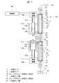
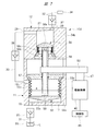
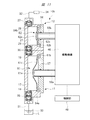
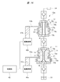
図1に示される液体供給装置10aは、一次側ポンプ11とこれに直列に接続される二次側ポンプ12とを有している。一次側ポンプ11は管状のポンプケース13とこの内部に組み込まれる管状の一次側ポンプ部材としてのチューブフラム14とを有している。チューブフラム14の一端部には流入側の端板15が取り付けられ、他端部には流出側の端板16が取り付けられている。チューブフラム14の内部は一次側ポンプ室17となっており、一次側ポンプ室17は端板15に形成された一次側流入口18と、端板16に形成された一次側吐出口19とに連通している。チューブフラム14の外側とポンプケース13の内側との間には駆動室21が形成されている。   The liquid supply apparatus 10a shown in FIG. 1 has a primary side pump 11 and a secondary side pump 12 connected in series thereto. The primary pump 11 has a tubular pump case 13 and a tube diaphragm 14 as a tubular primary pump member incorporated therein. An end plate 15 on the inflow side is attached to one end portion of the tube frame 14, and an end plate 16 on the outflow side is attached to the other end portion. The inside of the tube diaphragm 14 is a primary side pump chamber 17, and the primary side pump chamber 17 is connected to a primary side inlet 18 formed in the end plate 15 and a primary side discharge port 19 formed in the end plate 16. Communicate. A drive chamber 21 is formed between the outside of the tube frame 14 and the inside of the pump case 13.

二次側ポンプ12は、一次側ポンプ11と同様に、管状のポンプケース23とこの内部に組み込まれる管状の二次側ポンプ部材としてのチューブフラム24とを有している。チューブフラム24の一端部には流入側の端板25が取り付けられ、他端部には流出側の端板26が取り付けられている。チューブフラム24の内部は二次側ポンプ室27となっており、二次側ポンプ室27は端板25に形成された二次側流入口28と、端板26に形成された二次側吐出口29とに連通している。チューブフラム24の外側とポンプケース23の内側との間には駆動室22が形成されている。   Similar to the primary side pump 11, the secondary side pump 12 includes a tubular pump case 23 and a tube diaphragm 24 as a tubular secondary side pump member incorporated therein. An end plate 25 on the inflow side is attached to one end portion of the tube frame 24, and an end plate 26 on the outflow side is attached to the other end portion. The inside of the tube diaphragm 24 is a secondary side pump chamber 27, and the secondary side pump chamber 27 has a secondary side inlet 28 formed in the end plate 25 and a secondary side discharge formed in the end plate 26. It communicates with the outlet 29. A drive chamber 22 is formed between the outside of the tube diaphragm 24 and the inside of the pump case 23.

一次側ポンプ11の一次側吐出口19は、連通側流路30により二次側ポンプ12の二次側流入口28に接続されている。一次側流入口18には吸入流路31が接続され、二次側吐出口29には吐出流路32が接続される。吸入流路31の先端部は、液体Lを収容する容器33に接続され、吐出流路32の先端には液体Lを被塗布物に供給する塗布具34が設けられている。例えば、この液体供給装置10aが半導体集積回路装置を製造するために、フォトレジスト液を半導体ウエハに供給するために使用される場合には、容器33内にはフォトレジスト液が収容され、塗布具34から被塗布物としての半導体ウエハにフォトレジスト液が塗布される。連通側流路30,吸入流路31および吐出流路32は、配管やホース等の中空の部材により形成されている。   The primary side discharge port 19 of the primary side pump 11 is connected to the secondary side inlet 28 of the secondary side pump 12 by the communication side flow path 30. A suction flow path 31 is connected to the primary side inlet 18, and a discharge flow path 32 is connected to the secondary side discharge port 29. The distal end portion of the suction flow path 31 is connected to a container 33 that stores the liquid L, and an applicator 34 that supplies the liquid L to an object to be coated is provided at the distal end of the discharge flow path 32. For example, when this liquid supply apparatus 10a is used to supply a photoresist liquid to a semiconductor wafer in order to manufacture a semiconductor integrated circuit device, the photoresist liquid is accommodated in the container 33, and the application tool A photoresist solution is applied from 34 to a semiconductor wafer as an object to be coated. The communication side flow path 30, the suction flow path 31, and the discharge flow path 32 are formed by hollow members such as pipes and hoses.

チューブフラム14は弾性変形自在の材料により形成されており、チューブフラム14の両端部は、端板15,16とポンプケース13との間に固定され、チューブフラム14のうち両端部の間の部分は径方向に弾性変形自在の弾性変形部14aとなっている。チューブフラム24もチューブフラム14と同様の材料により形成されており、チューブフラム24の両端部は、端板25,26とポンプケース23との間に固定され、チューブフラム24のうち両端部の間の部分は径方向に弾性変形自在の弾性変形部24aとなっている。それぞれのチューブフラム14,24の弾性変形部14a,24aが径方向に弾性変形すると、ポンプ室17,27は膨張収縮することになる。   The tube frame 14 is formed of an elastically deformable material, and both end portions of the tube frame 14 are fixed between the end plates 15 and 16 and the pump case 13. Is an elastically deformable portion 14a that is elastically deformable in the radial direction. The tube frame 24 is also made of the same material as the tube frame 14, and both end portions of the tube frame 24 are fixed between the end plates 25, 26 and the pump case 23, and between the both end portions of the tube frame 24. This portion is an elastically deformable portion 24a that is elastically deformable in the radial direction. When the elastic deformation portions 14a and 24a of the tube diaphragms 14 and 24 are elastically deformed in the radial direction, the pump chambers 17 and 27 are expanded and contracted.

この液体供給装置10aが半導体ウエハにフォトレジスト液を塗布するために使用されるときには、チューブフラム14,24はフォトレジスト液と反応しないように、例えばフッ素樹脂により形成される。ただし、チューブフラム14,24の材料としては、液体Lの種類によってはフッ素樹脂に限られず、径方向に弾性変形する材料であれば、他の樹脂材料でも良く、ゴム材料でも良い。   When the liquid supply apparatus 10a is used for applying a photoresist solution to a semiconductor wafer, the tube frames 14 and 24 are made of, for example, a fluororesin so as not to react with the photoresist solution. However, the material of the tube diaphragms 14 and 24 is not limited to the fluororesin depending on the type of the liquid L, and may be another resin material or a rubber material as long as the material elastically deforms in the radial direction.

一次側ポンプ11を吸入動作させるときには、チューブフラム14を径方向に膨張させて一次側ポンプ室17を膨張させる。これにより、容器33内の液体Lが一次側ポンプ室17内に吸入される。これに対し、一次側ポンプ11を吐出動作させるときには、チューブフラム14を径方向に収縮させて一次側ポンプ室17を収縮させる。これにより、一次側ポンプ室17内の液体は二次側ポンプ室27に吐出して注入される。   When the primary pump 11 is inhaled, the tube diaphragm 14 is expanded in the radial direction to expand the primary pump chamber 17. Thereby, the liquid L in the container 33 is sucked into the primary pump chamber 17. In contrast, when the primary pump 11 is discharged, the tube diaphragm 14 is contracted in the radial direction to contract the primary pump chamber 17. As a result, the liquid in the primary pump chamber 17 is discharged and injected into the secondary pump chamber 27.

一次側ポンプ11の吸入動作時に一次側ポンプ室17に容器33内の液体Lを案内し、一次側ポンプ11の吐出動作時に一次側ポンプ室17内の液体Lが容器33に逆流するのを防止するために、吸入流路31には流入側開閉弁として逆止弁35が設けられている。一次側ポンプ11の吸入動作時に連通側流路30を閉じ、一次側ポンプ11の吐出動作時に連通側流路30を開放して一次側ポンプ室17内の液体を二次側ポンプ室27に案内するために、連通側流路30には連通側開閉弁として逆止弁36が設けられている。   The liquid L in the container 33 is guided to the primary pump chamber 17 during the suction operation of the primary pump 11, and the liquid L in the primary pump chamber 17 is prevented from flowing back into the container 33 during the discharge operation of the primary pump 11. Therefore, a check valve 35 is provided in the suction flow path 31 as an inflow side on-off valve. The communication-side flow path 30 is closed during the suction operation of the primary pump 11, and the communication-side flow path 30 is opened during the discharge operation of the primary pump 11 to guide the liquid in the primary pump chamber 17 to the secondary pump chamber 27. For this purpose, a check valve 36 is provided in the communication-side flow path 30 as a communication-side on / off valve.

一次側ポンプ11のチューブフラム14を径方向に弾性変性して一次側ポンプ室17を膨張収縮させるために、駆動室21に液体等の非圧縮性の媒体Mを給排するポンプ駆動部材41aが一次側ポンプ11に設けられている。同様に、二次側ポンプ12のチューブフラム24を径方向に弾性変性して二次側ポンプ室27を膨張収縮させるために、駆動室22に液体等の非圧縮性の媒体Mを給排するポンプ駆動部材41bが二次側ポンプ12に設けられている。   In order to expand and contract the primary pump chamber 17 by elastically modifying the tube diaphragm 14 of the primary pump 11 in the radial direction, a pump drive member 41a for supplying and discharging an incompressible medium M such as liquid to the drive chamber 21 is provided. A primary pump 11 is provided. Similarly, in order to expand and contract the secondary pump chamber 27 by elastically modifying the tube diaphragm 24 of the secondary pump 12 in the radial direction, an incompressible medium M such as a liquid is supplied to and discharged from the drive chamber 22. A pump drive member 41 b is provided in the secondary pump 12.

ポンプ駆動部材41aは、シリンダ42aとこのシリンダ42a内に軸方向に往復動自在に装着されたピストン43aとを有している。シリンダ42aとピストン43aとにより媒体Mが収容される媒体室44aが形成され、媒体室44aは連通孔45aにより駆動室21に連通している。ピストン43aを駆動するために、空気圧シリンダや油圧シリンダ等の流体圧アクチュエータからなる駆動機構46aにより駆動される往復動ロッド47aにピストン43aが取り付けられている。同様に、ポンプ駆動部材41bは、シリンダ42bとこのシリンダ42b内に軸方向に往復動自在に装着されたピストン43bとを有している。シリンダ42bとピストン43bとにより媒体Mが収容される媒体室44bが形成され、媒体室44bは連通孔45bにより駆動室22に連通している。流体圧アクチュエータからなる駆動機構46bにより駆動される往復動ロッド47bにピストン43bが取り付けられている。このように、ポンプ部材としての両方のチューブフラム14,24はピストン43a,43bにより媒体Mを介して駆動される間接駆動型となっている。   The pump drive member 41a has a cylinder 42a and a piston 43a mounted in the cylinder 42a so as to be capable of reciprocating in the axial direction. A medium chamber 44a in which the medium M is accommodated is formed by the cylinder 42a and the piston 43a, and the medium chamber 44a communicates with the drive chamber 21 through a communication hole 45a. In order to drive the piston 43a, the piston 43a is attached to a reciprocating rod 47a driven by a drive mechanism 46a composed of a fluid pressure actuator such as a pneumatic cylinder or a hydraulic cylinder. Similarly, the pump drive member 41b has a cylinder 42b and a piston 43b that is reciprocally mounted in the cylinder 42b in the axial direction. The cylinder 42b and the piston 43b form a medium chamber 44b in which the medium M is accommodated, and the medium chamber 44b communicates with the drive chamber 22 through the communication hole 45b. A piston 43b is attached to a reciprocating rod 47b driven by a drive mechanism 46b composed of a fluid pressure actuator. As described above, both the tube diaphragms 14 and 24 as the pump members are of an indirect drive type driven by the pistons 43a and 43b via the medium M.

駆動機構46a,46bとしての流体圧アクチュエータに対する流体の供給と排出は、制御部48により制御される。駆動機構46a,46bとしては、流体圧アクチュエータに代えて電動モータとすることもできる。電動モータとした形態においては、制御部48により制御される電動モータにより往復動ロッド47a,47bが駆動される。   Supply and discharge of fluid to and from the fluid pressure actuators as the drive mechanisms 46a and 46b are controlled by the control unit 48. The drive mechanisms 46a and 46b may be electric motors instead of the fluid pressure actuators. In the form of the electric motor, the reciprocating rods 47 a and 47 b are driven by the electric motor controlled by the control unit 48.

一次側ポンプ11を駆動するためのポンプ駆動部材41aのピストン43aの断面積A1は、二次側ポンプ12を駆動するためのポンプ駆動部材41bのピストン43bの断面積A2よりも大きく設定されている。したがって、一次側ポンプ11と二次側ポンプ12のサイズを同一とし、両方のピストン43a,43bを同一の速度で駆動するようにすると、一次側ポンプ室17は二次側ポンプ室27よりも早い速度で膨張収縮することになる。これにより、一次側ポンプ11の吸入動作時における一次側ポンプ室17に吸入される吸入流速つまり単位時間当たりの吸入流量、および一次側ポンプ11の吐出動作時における一次側吐出口19から二次側ポンプ室27に吐出される液体の単位時間当たりの吐出流量は、二次側吐出口29から吐出する液体の吐出流量よりも多くなる。   The sectional area A1 of the piston 43a of the pump drive member 41a for driving the primary pump 11 is set larger than the sectional area A2 of the piston 43b of the pump drive member 41b for driving the secondary pump 12. . Therefore, if the sizes of the primary pump 11 and the secondary pump 12 are the same and both pistons 43a and 43b are driven at the same speed, the primary pump chamber 17 is faster than the secondary pump chamber 27. It will expand and contract at a speed. As a result, the suction flow rate sucked into the primary pump chamber 17 during the suction operation of the primary pump 11, that is, the suction flow rate per unit time, and the primary side discharge port 19 during the discharge operation of the primary side pump 11 from the secondary side. The discharge flow rate per unit time of the liquid discharged into the pump chamber 27 is larger than the discharge flow rate of the liquid discharged from the secondary side discharge port 29.

上述した液体供給装置10aにおいては、一次側ポンプ11と二次側ポンプ12が連通側流路30により接続されており、上述のように一次側ポンプ11の吸入流量および吐出流量が二次側ポンプ12の吐出流量よりも大きく設定されている。したがって、一次側ポンプ室17から二次側ポンプ室27に液体を吐出する一次側ポンプ11の吐出動作時には、二次側ポンプ室27に液体を充填して二次側ポンプ室27を膨張させながら、二次側吐出口29から液体を吐出して塗布具34から液体が塗布される。一方、一次側ポンプ室17への液体を吸入する一次側ポンプ11の吸入動作時には、二次側ポンプ12の吐出動作により二次側吐出口29から液体を吐出して塗布具34から液体が被塗布物に塗布される。このように、一次側ポンプ室17の吐出流量を二次側ポンプ室27の吸入流量よりも大きくすると、二次側ポンプ12の吸入動作時に二次側ポンプ12に液体を充填することができるとともに、二次側吐出口29から液体を吐出して塗布具34から液体を塗布できる。つまり、一方のポンプ室を膨張させるときに他方のポンプ室を収縮させることにより、塗布具34に連続的に液体を供給することができる。   In the liquid supply apparatus 10a described above, the primary side pump 11 and the secondary side pump 12 are connected by the communication side flow path 30, and the suction flow rate and the discharge flow rate of the primary side pump 11 are the secondary side pump as described above. The discharge flow rate is set to be larger than 12. Therefore, during the discharge operation of the primary pump 11 that discharges the liquid from the primary pump chamber 17 to the secondary pump chamber 27, the secondary pump chamber 27 is filled with the liquid and the secondary pump chamber 27 is expanded. Then, the liquid is applied from the applicator 34 by discharging the liquid from the secondary-side discharge port 29. On the other hand, during the suction operation of the primary pump 11 that sucks liquid into the primary pump chamber 17, the liquid is discharged from the secondary discharge port 29 by the discharge operation of the secondary pump 12 and the liquid is applied from the applicator 34. It is applied to the coating. As described above, when the discharge flow rate of the primary pump chamber 17 is larger than the suction flow rate of the secondary pump chamber 27, the secondary pump 12 can be filled with liquid during the suction operation of the secondary pump 12. The liquid can be applied from the applicator 34 by discharging the liquid from the secondary discharge port 29. That is, the liquid can be continuously supplied to the applicator 34 by contracting the other pump chamber when the one pump chamber is expanded.

図1に示されるように、ピストン43aの断面積A1は、ピストン43bの断面積A2よりも大きい面積に設定されているので、両方のピストン43a,43bを同一の速度で駆動しても、一次側ポンプ室17の吐出流量は二次側ポンプ室27の吐出流量よりも大きくなっている。これに対し、両方のピストン43a,43bの断面積を等しくした形態においては、ピストン43aの駆動速度をピストン43bの駆動速度よりも早くすることにより、一次側ポンプ室17の吐出流量を二次側ポンプ室27の吐出流量よりも大きくすることができる。両方のピストン43a,43bの断面積を相違させるとともに駆動速度を相違させることにより、一次側ポンプ室17の吐出流量を二次側ポンプ室27の吐出流量よりも大きくすることができる。さらに、一次側ポンプ室17に液体を吸入する時間と、一次側ポンプ室17から二次側ポンプ室27に液体を吐出する時間とを同一としても良く、相違させるようにしても良い。一次側ポンプ室17への液体吸入時間よりも一次側ポンプ室17から二次側ポンプ室27への液体吐出時間を長くすると、液体供給装置10aに対する液体の吸入動作を吐出動作よりも速くすることができる。   As shown in FIG. 1, the cross-sectional area A1 of the piston 43a is set to an area larger than the cross-sectional area A2 of the piston 43b. Therefore, even if both pistons 43a and 43b are driven at the same speed, the primary The discharge flow rate in the side pump chamber 17 is larger than the discharge flow rate in the secondary pump chamber 27. On the other hand, in the form in which the cross-sectional areas of both the pistons 43a and 43b are made equal, the discharge flow rate of the primary pump chamber 17 is set to the secondary side by making the drive speed of the piston 43a faster than the drive speed of the piston 43b. The discharge flow rate of the pump chamber 27 can be made larger. The discharge flow rate of the primary pump chamber 17 can be made larger than the discharge flow rate of the secondary pump chamber 27 by making the sectional areas of both the pistons 43a and 43b different and the drive speeds different. Furthermore, the time for sucking the liquid into the primary pump chamber 17 and the time for discharging the liquid from the primary pump chamber 17 to the secondary pump chamber 27 may be the same or different. When the liquid discharge time from the primary pump chamber 17 to the secondary pump chamber 27 is longer than the liquid suction time to the primary pump chamber 17, the liquid suction operation to the liquid supply device 10a is made faster than the discharge operation. Can do.

液体供給装置10aにより塗布具34に液体を供給するには、図1に示されるように一次側ポンプ11の一次側ポンプ室17が収縮し、二次側ポンプ12の二次側ポンプ室27が膨張した状態のもとで、ピストン43bを前進移動させて媒体室44b内の媒体Mを駆動室22に供給して、二次側ポンプ室27の液体を二次側吐出口29から吐出する。これにより、二次側ポンプ12は吐出動作となり、塗布具34に液体が供給される。ピストン43bの前進移動の開始と同時に、ピストン43aを後退移動させて媒体室44a内に駆動室21内の媒体Mを吸入する。これにより、一次側ポンプ11は吸入駆動され、一次側ポンプ室17が膨張してその内部に液体が容器33から吸入される。一次側ポンプ11の吸入動作時には、一次側ポンプ室17の膨張により逆止弁35を通って容器33内の液体Lが一次側ポンプ室17に案内され、逆止弁36により二次側ポンプ室27から一次側ポンプ室17への液体Lの逆流が阻止される。   In order to supply the liquid to the applicator 34 by the liquid supply device 10a, the primary pump chamber 17 of the primary pump 11 contracts and the secondary pump chamber 27 of the secondary pump 12 moves as shown in FIG. Under the expanded state, the piston 43b is moved forward to supply the medium M in the medium chamber 44b to the drive chamber 22, and the liquid in the secondary pump chamber 27 is discharged from the secondary discharge port 29. As a result, the secondary pump 12 performs a discharge operation, and the liquid is supplied to the applicator 34. Simultaneously with the start of the forward movement of the piston 43b, the piston 43a is moved backward to suck the medium M in the drive chamber 21 into the medium chamber 44a. As a result, the primary pump 11 is driven to suck, the primary pump chamber 17 expands, and the liquid is sucked from the container 33 therein. During the suction operation of the primary pump 11, the liquid L in the container 33 is guided to the primary pump chamber 17 through the check valve 35 due to the expansion of the primary pump chamber 17, and the secondary pump chamber is guided by the check valve 36. The backflow of the liquid L from 27 to the primary side pump chamber 17 is prevented.

この動作が完了して、一次側ポンプ11の一次側ポンプ室17が限度まで膨張し、二次側ポンプ12の二次側ポンプ室27が限度まで収縮した状態になったら、ピストン43aとピストン43bの動作が逆転する。ピストン43aを前進移動させて媒体室44a内の媒体Mを駆動室21内へ送る。これにより、一次側ポンプ11は吐出駆動され、一次側ポンプ室17が収縮してその内部の液体が二次側ポンプ12の二次側ポンプ室27へ送られる。ピストン43bを後退移動させて媒体Mを駆動室22内から媒体室44bへ送る。これにより二次側ポンプ12は吸入動作する。二次側ポンプ12の吸入流量よりも一次側ポンプ11の吐出流量の方が大きいので、その差分の流量が二次側吐出口29から吐出される。この動作中は、逆止弁35は閉じ、逆止弁36と逆止弁37は開いている。   When this operation is completed and the primary pump chamber 17 of the primary pump 11 expands to the limit and the secondary pump chamber 27 of the secondary pump 12 contracts to the limit, the piston 43a and the piston 43b The operation of is reversed. The piston 43a is moved forward to send the medium M in the medium chamber 44a into the drive chamber 21. Thus, the primary pump 11 is driven to discharge, the primary pump chamber 17 contracts, and the liquid inside thereof is sent to the secondary pump chamber 27 of the secondary pump 12. The piston 43b is moved backward to send the medium M from the drive chamber 22 to the medium chamber 44b. As a result, the secondary pump 12 performs a suction operation. Since the discharge flow rate of the primary pump 11 is larger than the suction flow rate of the secondary pump 12, the difference flow rate is discharged from the secondary discharge port 29. During this operation, the check valve 35 is closed and the check valve 36 and the check valve 37 are open.

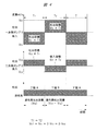
図2は液体供給装置におけるポンプの吐出動作と吸入動作の基本概念を示す概略図である。図3は液体供給装置10aにおけるそれぞれのポンプの吐出動作と吸入動作による塗布具34への液体の供給状態を示すタイムチャートである。   FIG. 2 is a schematic diagram showing the basic concept of the discharge operation and suction operation of the pump in the liquid supply apparatus. FIG. 3 is a time chart showing the supply state of the liquid to the applicator 34 by the discharge operation and the suction operation of each pump in the liquid supply apparatus 10a.

図2に示すように、一次側ポンプの吐出流量をVD1(ml/s)、二次側ポンプの吐出流量をVD2(ml/s)、一次側ポンプの吸入流量をVC1(ml/s)、二次側ポンプの吸入流量をVC2(ml/s)とする。また、一次側ポンプ11のポンプ容積をD1(ml)、二次側ポンプ12のポンプ容積をD2(ml)とする。   As shown in FIG. 2, the discharge flow rate of the primary pump is VD1 (ml / s), the discharge flow rate of the secondary pump is VD2 (ml / s), the suction flow rate of the primary pump is VC1 (ml / s), The suction flow rate of the secondary pump is set to VC2 (ml / s). The pump volume of the primary pump 11 is D1 (ml), and the pump volume of the secondary pump 12 is D2 (ml).

液体供給装置10aの初期状態を、一次側ポンプ室17が空となって吸引動作を待機している状態とし、二次側ポンプ室27には液体が充満されて吐出動作を待機している状態とする。この状態のもとで、時間T1の工程Aが実行される。この工程Aは、二次側ポンプ12だけが吐出し、一次側ポンプ11は吸入する期間となる。この工程Aにおいては、二次側ポンプ12が吐出を開始してからその容積分の液体を全て吐出完了するまでの時間と、空の一次側ポンプ11に液体を充満させる時間とが同じである。   The initial state of the liquid supply device 10a is a state in which the primary pump chamber 17 is empty and waiting for the suction operation, and the secondary pump chamber 27 is filled with liquid and waiting for the discharge operation And Under this state, the process A at time T1 is executed. This process A is a period during which only the secondary pump 12 discharges and the primary pump 11 sucks. In this step A, the time from when the secondary pump 12 starts to discharge until the discharge of all the volume of liquid is completed is the same as the time to fill the empty primary pump 11 with liquid. .

この時間T1を、ポンプ室17の容積つまり一次側ポンプ11の容積D1と、一次側ポンプ11の吸入流量VC1により示すと、T1=D1/VC1となる。一方、ポンプ室27の容積つまり二次側ポンプ12の容積D2と、二次側ポンプ12の吐出流量VD2により示すと、T1=D2/VD2となる。一次側ポンプ11と二次側ポンプ12の作動時間は同じであるから、以下のような関係式が求められる。   When this time T1 is represented by the volume of the pump chamber 17, that is, the volume D1 of the primary pump 11 and the suction flow rate VC1 of the primary pump 11, T1 = D1 / VC1. On the other hand, when indicated by the volume of the pump chamber 27, that is, the volume D2 of the secondary pump 12, and the discharge flow rate VD2 of the secondary pump 12, T1 = D2 / VD2. Since the operation time of the primary side pump 11 and the secondary side pump 12 is the same, the following relational expression is calculated | required.

D1/VC1=D2/VD2 …(1)
工程Aにおける塗布具34への液体の供給流量NDAは、VD2となる。
D1 / VC1 = D2 / VD2 (1)
The liquid supply flow rate NDA to the applicator 34 in the process A is VD2.

次いで、時間T2の工程Bが実行される。この工程Bは、二次側ポンプ12は吸入と吐出を行い、一次側ポンプ11は吐出する期間である。この工程Bにおいては、二次側ポンプ12が吸入を開始してからその容積分の液体が満たされるまでの時間と、一次側ポンプ11に満たされた液体が全て二次側ポンプ12に吐出されるまでの時間が同じである。   Next, step B at time T2 is executed. This process B is a period in which the secondary pump 12 performs suction and discharge, and the primary pump 11 discharges. In this step B, the time from the start of suction by the secondary pump 12 until the volume of liquid is filled, and the liquid filled in the primary pump 11 are all discharged to the secondary pump 12. The time to complete is the same.

この時間T2を、一次側ポンプ11の容積D1と一次側ポンプ11の吐出流量VD1により示すと、T2=D1/VD1となる。一方、二次側ポンプ12の容積D2と二次側ポンプ12の吸入流量VC2により示すと、T2=D2/VC2となる。一次側ポンプ11と二次側ポンプ12の作動時間は同じであるから、以下の関係式が求められる。   When this time T2 is indicated by the volume D1 of the primary pump 11 and the discharge flow rate VD1 of the primary pump 11, T2 = D1 / VD1. On the other hand, when indicated by the volume D2 of the secondary pump 12 and the suction flow rate VC2 of the secondary pump 12, T2 = D2 / VC2. Since the operation time of the primary side pump 11 and the secondary side pump 12 is the same, the following relational expression is calculated | required.

D1/VD1=D2/VC2 …(2)
この工程Bにおける塗布具34への液体の供給流量NDBはVD1−VC2となる。
D1 / VD1 = D2 / VC2 (2)
In this step B, the liquid supply flow rate NDB to the applicator 34 is VD1-VC2.

工程Aと工程Bにおける塗布具34からの吐出流量つまり供給流量が同じであるから、以下のようになる。   Since the discharge flow rate from the applicator 34 in the process A and the process B, that is, the supply flow rate is the same, it is as follows.

NDA=VD2=NDB=VD1−VC2
つまり、VD2=VD1−VC2 …(3)
式(1)(2)からD1、D2を消去して、
VD2/VC1=VC2/VD1 …(4)
この(4)式の左辺は、工程AにおけるVD2/VC1の比率を示し、右辺は、工程BにおけるVC2/VD1の比率を示しており、一次側ポンプ11と二次側ポンプ12の吸入吐出量が(4)式を満たせば、液体供給装置から連続的に液体を塗布具34に供給することができる。工程Aと工程Bとを繰り返すことにより、塗布具34には連続的に液体が供給される。
NDA = VD2 = NDB = VD1-VC2
That is, VD2 = VD1-VC2 (3)
Erasing D1 and D2 from equations (1) and (2),
VD2 / VC1 = VC2 / VD1 (4)
The left side of the equation (4) shows the ratio of VD2 / VC1 in the process A, and the right side shows the ratio of VC2 / VD1 in the process B. The intake and discharge amounts of the primary pump 11 and the secondary pump 12 are shown in FIG. If (4) is satisfied, the liquid can be continuously supplied from the liquid supply device to the applicator 34. By repeating the process A and the process B, the liquid is continuously supplied to the applicator 34.

上述した液体供給装置10aによる塗布具34への液体の吐出動作を、以下のような条件として行った。一次側ポンプ11の吐出流量VD1を5ml/s、吸入流量VC1を7.5ml/s、容積D1を10mlに設定した。二次側ポンプ12の吐出流量VD2を3ml/s、吸入流量VC2を2ml/s、容積D2を4mlに設定した。工程Aの動作時間T1を4/3秒、工程Bの動作時間T2を2秒に設定した。   The liquid discharging operation to the applicator 34 by the liquid supply apparatus 10a described above was performed under the following conditions. The discharge flow rate VD1 of the primary pump 11 was set to 5 ml / s, the suction flow rate VC1 was set to 7.5 ml / s, and the volume D1 was set to 10 ml. The discharge flow rate VD2 of the secondary pump 12 was set to 3 ml / s, the suction flow rate VC2 was set to 2 ml / s, and the volume D2 was set to 4 ml. The operation time T1 of the process A was set to 4/3 seconds, and the operation time T2 of the process B was set to 2 seconds.

工程Aにおいては、二次側ポンプ12からその吐出流量VD2である3ml/sの液体が塗布具34に供給される。この吐出動作と同時に一次側ポンプ11は吸入動作を行う。工程Aの動作時間T1は、4/3秒に設定されているので、二次側ポンプ12は3ml/sの吐出流量VD2で4/3秒間吐出動作し、二次側ポンプ12の容量D2である4mlが全て吐出される。一次側ポンプ11は7.5ml/sの吸入流量VC1で4/3秒間吸引動作し、一次側ポンプ11の容積D1である10mlの液体が完全にチャージされる。   In step A, a liquid of 3 ml / s as the discharge flow rate VD2 is supplied from the secondary pump 12 to the applicator 34. Simultaneously with this discharge operation, the primary pump 11 performs a suction operation. Since the operation time T1 of the process A is set to 4/3 seconds, the secondary pump 12 performs the discharge operation for 4/3 seconds at the discharge flow rate VD2 of 3 ml / s, and the capacity D2 of the secondary pump 12 All 4ml is discharged. The primary pump 11 performs a suction operation for 4/3 seconds at a suction flow rate VC1 of 7.5 ml / s, and 10 ml of the liquid D1 of the primary pump 11 is completely charged.

工程Bにおいては、二次側ポンプ12が吸引動作と吐出動作とを同時に行い、一次側ポンプ11が吐出動作する。このときには、一次側ポンプ11から二次側ポンプ12に5ml/sの吐出流量VD1で液体が注入され、二次側ポンプ12は2ml/sの吸入流量VC2で吸入動作を行うので、吐出流量VD1と吸入流量VC2の差である3ml/sの流量で液体が塗布具34に供給される。工程Bにおいては、二次側ポンプ12は2ml/sの流量で2秒間の吸引動作により、二次側ポンプ12の容積D2である4mlの液体が二次側ポンプ12に完全にチャージされる。一次側ポンプ11は5ml/sの流量で2秒間の吐出動作を行うので、一次側ポンプ11の容積D1である10mlの液体を全て吐出する。   In step B, the secondary pump 12 performs the suction operation and the discharge operation simultaneously, and the primary pump 11 performs the discharge operation. At this time, liquid is injected from the primary pump 11 to the secondary pump 12 at a discharge flow rate VD1 of 5 ml / s, and the secondary pump 12 performs a suction operation at a suction flow rate VC2 of 2 ml / s. The liquid is supplied to the applicator 34 at a flow rate of 3 ml / s, which is the difference between the suction flow rate VC2 and the suction flow rate VC2. In the process B, the secondary pump 12 is completely charged to the secondary pump 12 with 4 ml of the volume D2 of the secondary pump 12 by the suction operation for 2 seconds at a flow rate of 2 ml / s. Since the primary pump 11 performs a discharge operation for 2 seconds at a flow rate of 5 ml / s, all the 10 ml of liquid that is the volume D1 of the primary pump 11 is discharged.

このように、VC1を7.5ml/sとし、VD1を5ml/sとし、VD2を3ml/sとし、VC2を2ml/sとすると、上記(4)式の左辺は3/7.5であり、右辺は2/5であり、(4)式を満たすことになる。   Thus, when VC1 is 7.5 ml / s, VD1 is 5 ml / s, VD2 is 3 ml / s, and VC2 is 2 ml / s, the left side of the above equation (4) is 3 / 7.5. , The right side is 2/5, which satisfies equation (4).

上述した場合には、工程Aと工程Bにおける塗布具34に対する液体の供給流量は、同一の3ml/sに設定されているが、工程Aと工程Bとで塗布具34に対する液体の供給流量を相違させることもできる。その場合には、工程Aにおける塗布具34への供給流量NDAと工程Bにおける塗布具34への供給流量NDBは、相違することになる。   In the case described above, the liquid supply flow rate to the applicator 34 in the process A and the process B is set to the same 3 ml / s, but the liquid supply flow rate to the applicator 34 is set in the process A and the process B. It can also be different. In that case, the supply flow rate NDA to the applicator 34 in the process A and the supply flow rate NDB to the applicator 34 in the process B are different.

図4は塗布具への液体の供給動作の変形例を示すタイムチャートである。この供給動作が行われる液体供給装置10aは、ピストン43aの面積がピストン43bの面積の2倍となっており、工程Aと工程Bの作動時間が同一(T1=T2 )に設定されている。したがって、図4に示されるように、一次側ポンプ11の単位時間当たりの吸入流量VC1と吐出流量VD1は同一の流量であり、二次側ポンプ12の単位時間当たりの吐出流量VD2と吸入流量VC2は同一の流量であって、二次側ポンプ12の流量VC2とVD2は、一次側ポンプ11のそれぞれの流量VC1、VD1の2分の1となる。   FIG. 4 is a time chart showing a modification of the liquid supply operation to the applicator. In the liquid supply apparatus 10a in which this supply operation is performed, the area of the piston 43a is twice the area of the piston 43b, and the operation times of the process A and the process B are set to be the same (T1 = T2). Therefore, as shown in FIG. 4, the suction flow rate VC1 and discharge flow rate VD1 per unit time of the primary pump 11 are the same flow rate, and the discharge flow rate VD2 and suction flow rate VC2 per unit time of the secondary pump 12 Are the same flow rate, and the flow rates VC2 and VD2 of the secondary pump 12 are half of the flow rates VC1 and VD1 of the primary pump 11, respectively.

図4に示されるように、一次側ポンプ11が吸入動作を行い、二次側ポンプ12が吐出動作を行う工程Aにおいては、二次側ポンプ12の吐出流量VD2の2倍の吸入流量VC1で一次側ポンプ11が吸入動作を行う。このときの塗布具34への液体の供給流量NDAは、二次側ポンプ12の吐出流量VD2となる。一方、二次側ポンプ12が吸引動作と吐出動作を行う工程Bにおいては、一次側ポンプ11は、二次側ポンプ12の吸入流量VC2の2倍の吐出流量VD1で二次側ポンプ12に吐出される。したがって、一次側ポンプ11の吐出動作時には、二次側吐出口29から塗布具34に吐出される液体の吐出流量と、二次側ポンプ室27の膨張速度に応じた液体の吸入流量との合計の流量が二次側ポンプ室27に供給される。このように、一次側ポンプ11の吐出動作時にも、一次側ポンプ11の吸入動作時と同一の流量となって二次側吐出口29から液体が塗布具34に供給される。したがって、一次側ポンプ11の吸入動作時と吐出動作時とのいずれにおいても、二次側吐出口29からは、常に一定の流量の液体が吐出流路32により塗布具34に向けて吐出される。   As shown in FIG. 4, in the process A in which the primary pump 11 performs the suction operation and the secondary pump 12 performs the discharge operation, the suction flow rate VC1 is twice the discharge flow rate VD2 of the secondary pump 12. The primary pump 11 performs a suction operation. The liquid supply flow rate NDA to the applicator 34 at this time is the discharge flow rate VD2 of the secondary pump 12. On the other hand, in the process B in which the secondary pump 12 performs the suction operation and the discharge operation, the primary pump 11 discharges to the secondary pump 12 at a discharge flow rate VD1 that is twice the suction flow rate VC2 of the secondary pump 12. Is done. Therefore, during the discharge operation of the primary side pump 11, the sum of the liquid discharge flow rate discharged from the secondary side discharge port 29 to the applicator 34 and the liquid suction flow rate according to the expansion speed of the secondary side pump chamber 27. Is supplied to the secondary pump chamber 27. In this way, even during the discharge operation of the primary pump 11, the liquid is supplied from the secondary discharge port 29 to the applicator 34 at the same flow rate as during the suction operation of the primary pump 11. Therefore, in both the suction operation and the discharge operation of the primary pump 11, a constant flow rate of liquid is always discharged from the secondary discharge port 29 toward the applicator 34 through the discharge flow path 32. .

吐出流路32には塗布具34に向かって連続的に液体が流れるので、液体供給装置10aが使用されるときには、吐出流路32には流路を開閉する開閉弁を設けることは不要である。ただし、二次側ポンプ室27が確実に膨張収縮動作するか否かの動作テストをするために、図1に示されるように、逆止弁37が吐出流路32に設けられている。なお、それぞれの逆止弁35〜37としては、流路を開閉する電磁弁やエアオペレート弁を使用するようにしても良い。電磁弁等が使用されるときには、それぞれの開閉動作は制御部からの信号により制御される。   Since the liquid continuously flows in the discharge channel 32 toward the applicator 34, when the liquid supply device 10a is used, it is not necessary to provide the on-off valve for opening and closing the channel in the discharge channel 32. . However, as shown in FIG. 1, a check valve 37 is provided in the discharge flow path 32 in order to perform an operation test as to whether or not the secondary side pump chamber 27 is surely inflated and contracted. In addition, as each check valve 35-37, you may make it use the solenoid valve and air operated valve which open and close a flow path. When a solenoid valve or the like is used, each opening / closing operation is controlled by a signal from the control unit.

上述のように、一次側と二次側の2つのポンプ室を介して直列となった流路により容器33と塗布具34とが接続されることになるので、液体内に気泡が混入していても、流路内に気泡が滞留することがない。しかも、流路を形成する配管やホース等をポンプ周囲に這い回すことがなくなり、液体供給装置10aのメンテナンス時の操作性を向上させることができる。   As described above, since the container 33 and the applicator 34 are connected by the flow path in series through the two pump chambers on the primary side and the secondary side, bubbles are mixed in the liquid. However, bubbles do not stay in the flow path. In addition, pipes, hoses, and the like that form the flow path are not wound around the pump, and the operability during maintenance of the liquid supply apparatus 10a can be improved.

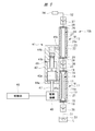
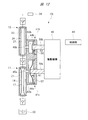
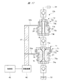
図5は他の実施の形態である液体供給装置10bを示す断面図である。この液体供給装置10bにおける一次側ポンプ11と二次側ポンプ12は、上述した液体供給装置10aと同様の構造である。これに対し、上述した液体供給装置10aにおいては両方のポンプ11,12が別々のポンプ駆動部材41a,41bにより駆動される二軸構造であるのに対し、液体供給装置10bの両方のポンプ11,12は1つのポンプ駆動部材41により駆動される。ポンプ駆動部材41はシリンダ42を有し、このシリンダ42には一次側ポンプ室17と二次側ポンプ室27とが設けられている。媒体室44aを膨張収縮するピストン43aと、媒体室44bを膨張収縮するピストン43bとが一体となってシリンダ42に軸方向に往復動自在に装着されており、ポンプ駆動部材41は一軸構造となっている。ピストン43aの断面積A1は、ピストン43bの断面積A2よりも大きい。   FIG. 5 is a cross-sectional view showing a liquid supply apparatus 10b according to another embodiment. The primary pump 11 and the secondary pump 12 in the liquid supply apparatus 10b have the same structure as the liquid supply apparatus 10a described above. On the other hand, in the liquid supply apparatus 10a described above, both pumps 11 and 12 have a biaxial structure driven by separate pump drive members 41a and 41b, whereas both pumps 11 and 12 of the liquid supply apparatus 10b. 12 is driven by one pump drive member 41. The pump drive member 41 has a cylinder 42, and the cylinder 42 is provided with a primary pump chamber 17 and a secondary pump chamber 27. A piston 43a that expands and contracts the medium chamber 44a and a piston 43b that expands and contracts the medium chamber 44b are integrally attached to the cylinder 42 so as to be capable of reciprocating in the axial direction, and the pump drive member 41 has a uniaxial structure. ing. The cross-sectional area A1 of the piston 43a is larger than the cross-sectional area A2 of the piston 43b.

一軸構造となったピストン43a,43bは、駆動機構46の往復動ロッド47により同期して駆動される。ピストン43aにより媒体室44aを膨張させて駆動室21を介して一次側ポンプ室17を膨張させるときには、ピストン43bにより媒体室44bを収縮させて駆動室22を介して二次側ポンプ室27が収縮する。一方、ピストン43aにより媒体室44aを収縮させて一次側ポンプ室17を収縮させるときには、ピストン43bにより媒体室44bが膨張して二次側ポンプ室27が膨張する。この液体供給装置10bにおいては、両方のポンプの吐出動作と吸入動作による塗布具34への液体の供給動作は、上述した液体供給装置10aと同様となる。なお、図5において符号49は息付き孔を示す。   The pistons 43 a and 43 b having a uniaxial structure are driven in synchronization by a reciprocating rod 47 of the drive mechanism 46. When the medium chamber 44a is expanded by the piston 43a and the primary pump chamber 17 is expanded via the drive chamber 21, the medium chamber 44b is contracted by the piston 43b and the secondary pump chamber 27 is contracted via the drive chamber 22. To do. On the other hand, when the medium chamber 44a is contracted by the piston 43a and the primary pump chamber 17 is contracted, the medium chamber 44b is expanded by the piston 43b and the secondary pump chamber 27 is expanded. In this liquid supply apparatus 10b, the liquid supply operation to the applicator 34 by the discharge operation and the suction operation of both pumps is the same as that of the liquid supply apparatus 10a described above. In FIG. 5, reference numeral 49 denotes a breathing hole.

図5に示されるように、1つのポンプ駆動部材41により2つのポンプ11,12を駆動する形態においては、液体供給装置10bの構造を液体供給装置10aよりもシンプルとすることができる。   As shown in FIG. 5, in the form in which the two pumps 11 and 12 are driven by one pump driving member 41, the structure of the liquid supply apparatus 10b can be made simpler than the liquid supply apparatus 10a.

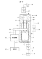
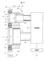
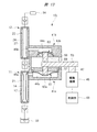
図6はさらに他の実施の形態である液体供給装置10cを示す断面図である。この液体供給装置10cは、一次側ポンプ11と二次側ポンプ12がシリンダ50に設けられている。シリンダ50には一次側ポンプ室17と二次側ポンプ室27とが設けられている。一次側ポンプ室17は一次側流入口18と一次側吐出口19とに連通し、二次側ポンプ室27は二次側流入口28と二次側吐出口29とに連通する。一次側ポンプ室17はシリンダ50とピストン51により区画され、二次側ポンプ室27はシリンダ50とピストン52とにより区画されている。一次側ポンプ室17を膨張収縮する一次側ポンプ部材としてのピストン51と、二次側ポンプ室27を膨張収縮する二次側ポンプ部材としてのピストン52とが同軸状に一体となってシリンダ50に往復動自在に装着されている。両方のピストン51,52は、流体圧アクチュエータ等からなる駆動機構46の往復動ロッド47に連結部材53により連結されており、1つの駆動機構46により同期して駆動される。   FIG. 6 is a cross-sectional view showing a liquid supply apparatus 10c which is still another embodiment. In the liquid supply device 10c, a primary pump 11 and a secondary pump 12 are provided in a cylinder 50. The cylinder 50 is provided with a primary pump chamber 17 and a secondary pump chamber 27. The primary side pump chamber 17 communicates with the primary side inlet 18 and the primary side outlet 19, and the secondary side pump chamber 27 communicates with the secondary side inlet 28 and the secondary side outlet 29. The primary pump chamber 17 is partitioned by a cylinder 50 and a piston 51, and the secondary pump chamber 27 is partitioned by a cylinder 50 and a piston 52. A piston 51 as a primary pump member that expands and contracts the primary pump chamber 17 and a piston 52 as a secondary pump member that expands and contracts the secondary pump chamber 27 are coaxially integrated into the cylinder 50. It is mounted so that it can reciprocate. Both pistons 51 and 52 are connected to a reciprocating rod 47 of a drive mechanism 46 composed of a fluid pressure actuator or the like by a connecting member 53, and are driven in synchronization by one drive mechanism 46.

このように、液体供給装置10cは、ポンプ部材がピストン51,52により形成されたピストン構造ないしプランジャ構造となっている。ピストン51の断面積A1はピストン52の断面積A2よりも大きく、両方のポンプの吐出動作と吸入動作による塗布具34への液体の供給状態は、上述した場合と同様となる。   Thus, the liquid supply apparatus 10c has a piston structure or a plunger structure in which the pump member is formed by the pistons 51 and 52. The cross-sectional area A1 of the piston 51 is larger than the cross-sectional area A2 of the piston 52, and the liquid supply state to the applicator 34 by the discharge operation and suction operation of both pumps is the same as described above.

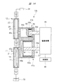
図7はさらに他の実施の形態である液体供給装置10dを示す断面図である。この液体供給装置10dは、一次側ポンプ11がポンプケース54aに設けられ、二次側ポンプ12がポンプケース54bに設けられており、両方のポンプケース54a,54bは直列となって組み付けられている。ポンプケース54aには一次側ポンプ室17が設けられ、ポンプケース54bには二次側ポンプ室27が設けられている。一次側ポンプ室17は一次側流入口18と一次側吐出口19とに連通し、二次側ポンプ室27は二次側流入口28と二次側吐出口29とに連通する。一次側ポンプ室17を膨張収縮する一次側ポンプ部材としてのベローズ55と、二次側ポンプ室27を膨張収縮する二次側ポンプ部材としてのベローズ56とが同軸状に一体となってポンプケース54a,54bに軸方向に弾性変形自在に装着されている。   FIG. 7 is a cross-sectional view showing a liquid supply apparatus 10d which is still another embodiment. In the liquid supply apparatus 10d, the primary pump 11 is provided in the pump case 54a, the secondary pump 12 is provided in the pump case 54b, and both the pump cases 54a and 54b are assembled in series. . The pump case 54a is provided with the primary pump chamber 17, and the pump case 54b is provided with the secondary pump chamber 27. The primary side pump chamber 17 communicates with the primary side inlet 18 and the primary side outlet 19, and the secondary side pump chamber 27 communicates with the secondary side inlet 28 and the secondary side outlet 29. A bellows 55 as a primary pump member that expands and contracts the primary pump chamber 17 and a bellows 56 as a secondary pump member that expands and contracts the secondary pump chamber 27 are coaxially integrated into a pump case 54a. 54b are elastically deformable in the axial direction.

ベローズ55は、先端側のディスク部55aと、ポンプケース54aに固定される基端部側の環状部55bとを有し、ディスク部55aと環状部55bの間には軸方向に弾性変形する弾性変形部55cが一体に設けられている。環状部55bは固定ディスク57によりポンプケース54aに固定されている。弾性変形部55cが軸方向に延びると一次側ポンプ室17は収縮し、軸方向に収縮すると一次側ポンプ室17は膨張する。   The bellows 55 includes a disk portion 55a on the distal end side and an annular portion 55b on the proximal end side fixed to the pump case 54a, and elastically deforms between the disk portion 55a and the annular portion 55b in the axial direction. The deformation portion 55c is provided integrally. The annular portion 55b is fixed to the pump case 54a by a fixed disk 57. When the elastic deformation portion 55c extends in the axial direction, the primary pump chamber 17 contracts, and when the elastic deformation portion 55c contracts in the axial direction, the primary pump chamber 17 expands.

ベローズ56は、ベローズ55と同様に、先端側のディスク部56aと、ポンプケース54bに固定される基端部側の環状部56bとを有し、ディスク部56aと環状部56bの間には軸方向に弾性変形する弾性変形部56cが一体に設けられている。環状部56bは固定ディスク58によりポンプケース54bに固定されている。弾性変形部56cが軸方向に延びると二次側ポンプ室27は収縮し、軸方向に収縮すると二次側ポンプ室27は膨張する。両方のディスク部55a,56aは、それぞれの固定ディスク57,58を貫通する往復動ロッド59により連結されている。往復動ロッド59は連結部材53により駆動機構46の往復動ロッド47に連結されており、両方のベローズ55,56は同期して逆方向に駆動される。   As with the bellows 55, the bellows 56 includes a disk portion 56a on the distal end side and an annular portion 56b on the proximal end side fixed to the pump case 54b, and a shaft is interposed between the disk portion 56a and the annular portion 56b. An elastic deformation portion 56c that is elastically deformed in the direction is integrally provided. The annular portion 56b is fixed to the pump case 54b by a fixed disk 58. When the elastic deformation portion 56c extends in the axial direction, the secondary pump chamber 27 contracts, and when the elastic deformation portion 56c contracts in the axial direction, the secondary pump chamber 27 expands. Both disk portions 55a and 56a are connected by a reciprocating rod 59 that penetrates the fixed disks 57 and 58, respectively. The reciprocating rod 59 is connected to the reciprocating rod 47 of the drive mechanism 46 by a connecting member 53, and both bellows 55 and 56 are driven in the reverse direction in synchronization.

このように、液体供給装置10dはポンプ部材がベローズ55,56により形成されたベローズ構造となっている。ベローズ55の平均有効面積A1はベローズ56の平均有効面積A2よりも大きく設定されている。なお、それぞれのベローズ55,56の内側は、固定ディスク57,58に設けられた図示しない息付き孔により大気に開放されている。   Thus, the liquid supply apparatus 10d has a bellows structure in which the pump member is formed by the bellows 55 and 56. The average effective area A1 of the bellows 55 is set larger than the average effective area A2 of the bellows 56. The inner sides of the bellows 55 and 56 are open to the atmosphere by breathing holes (not shown) provided in the fixed disks 57 and 58.

図8はさらに他の実施の形態である液体供給装置10eを示す断面図である。この液体供給装置10eは、一次側ポンプ11がポンプケース54aに設けられ、二次側ポンプ12がポンプケース54bに設けられており、両方のポンプケース54a,54bは直列となって組み付けられている。ポンプケース54aには一次側ポンプ室17が設けられ、ポンプケース54bには二次側ポンプ室27が設けられている。一次側ポンプ室17は一次側流入口18と一次側吐出口19とに連通し、二次側ポンプ室27は二次側流入口28と二次側吐出口29とに連通する。一次側ポンプ室17を膨張収縮する一次側ポンプ部材としてのダイヤフラム61と、二次側ポンプ室27を膨張収縮する二次側ポンプ部材としてのダイヤフラム62とが同軸状に一体となってポンプケース54a,54bに軸方向に弾性変形自在に装着されている。   FIG. 8 is a cross-sectional view showing a liquid supply apparatus 10e which is still another embodiment. In the liquid supply apparatus 10e, the primary pump 11 is provided in the pump case 54a, the secondary pump 12 is provided in the pump case 54b, and both the pump cases 54a and 54b are assembled in series. . The pump case 54a is provided with the primary pump chamber 17, and the pump case 54b is provided with the secondary pump chamber 27. The primary side pump chamber 17 communicates with the primary side inlet 18 and the primary side outlet 19, and the secondary side pump chamber 27 communicates with the secondary side inlet 28 and the secondary side outlet 29. A diaphragm 61 as a primary pump member that expands and contracts the primary pump chamber 17 and a diaphragm 62 as a secondary pump member that expands and contracts the secondary pump chamber 27 are coaxially integrated into a pump case 54a. 54b are elastically deformable in the axial direction.

ダイヤフラム61は、先端側のディスク部61aと、ポンプケース54aに固定される基端部側の環状部61bとを有し、ディスク部61aと環状部61bの間には軸方向に弾性変形する弾性変形部61cが一体に設けられている。環状部61bは固定ディスク57によりポンプケース54aに固定されている。弾性変形部61cが軸方向に突き出す方向に弾性変形すると一次側ポンプ室17は収縮し、軸方向に後退する方向に弾性変形すると一次側ポンプ室17は膨張する。   The diaphragm 61 includes a disc portion 61a on the distal end side and an annular portion 61b on the base end portion side fixed to the pump case 54a, and elastically deforms between the disc portion 61a and the annular portion 61b in the axial direction. The deformation part 61c is provided integrally. The annular portion 61b is fixed to the pump case 54a by a fixed disk 57. When the elastically deforming portion 61c is elastically deformed in the protruding direction, the primary pump chamber 17 contracts, and when the elastically deforming portion 61c is elastically deformed in the axially retracting direction, the primary pump chamber 17 expands.

ダイヤフラム62は、ダイヤフラム61と同様に、先端側のディスク部62aと、ポンプケース54bに固定される基端部側の環状部62bとを有し、ディスク部62aと環状部62bの間には軸方向に弾性変形する弾性変形部62cが一体に設けられている。環状部62bは固定ディスク58によりポンプケース54bに固定されている。弾性変形部62cが軸方向に突き出す方向に弾性変形すると二次側ポンプ室27は収縮し、軸方向に後退する方向に弾性変形すると二次側ポンプ室27は膨張する。   Similar to the diaphragm 61, the diaphragm 62 includes a disc portion 62a on the distal end side and an annular portion 62b on the proximal end side fixed to the pump case 54b, and a shaft is interposed between the disc portion 62a and the annular portion 62b. An elastic deformation portion 62c that elastically deforms in the direction is integrally provided. The annular portion 62b is fixed to the pump case 54b by a fixed disk 58. When the elastically deforming portion 62c is elastically deformed in the protruding direction, the secondary pump chamber 27 contracts, and when the elastically deforming portion 62c elastically deforms in the axially retracting direction, the secondary pump chamber 27 expands.

両方のディスク部61a,62aは、それぞれの固定ディスク57,58を貫通する往復動ロッド59により連結されている。往復動ロッド59は連結部材53により駆動機構46の往復動ロッド47に連結されており、両方のダイヤフラム61,62は同期して逆方向に駆動される。   Both disk portions 61a and 62a are connected by a reciprocating rod 59 that penetrates the fixed disks 57 and 58, respectively. The reciprocating rod 59 is connected to the reciprocating rod 47 of the drive mechanism 46 by a connecting member 53, and both diaphragms 61 and 62 are driven in the opposite direction in synchronization.

このように、液体供給装置10eはポンプ部材がダイヤフラム61,62により形成されたダイヤフラム構造となっている。ダイヤフラム61の弾性変形部61cの平均有効面積はダイヤフラム62の弾性変形部62cの平均有効面積よりも大きくなっている。なお、それぞれのダイヤフラム61,62の内側は、固定ディスク57,58に設けられた図示しない息付き孔により大気に開放されている。   Thus, the liquid supply apparatus 10e has a diaphragm structure in which the pump member is formed by the diaphragms 61 and 62. The average effective area of the elastic deformation portion 61 c of the diaphragm 61 is larger than the average effective area of the elastic deformation portion 62 c of the diaphragm 62. The insides of the diaphragms 61 and 62 are opened to the atmosphere by breathing holes (not shown) provided in the fixed disks 57 and 58.

図9〜図17はそれぞれ他の実施の形態である液体供給装置10f〜10nを示す断面図である。図9に示される液体供給装置10fは、図6に示した液体供給装置10cと同様にピストン構造となっている。液体供給装置10fにおけるポンプ部材としての2つのピストン51,52は、並列に配置されたシリンダ50a,50bに設けられている。図6に示した液体供給装置10cにおいては2つのピストン51,52が同軸となっているのに対し、液体供給装置10fにおいては平行となっている。ピストン51は往復動ロッド47aに取り付けられ、ピストン52は往復動ロッド47bに取り付けられており、それぞれの往復動ロッド47a,47bは駆動機構46により駆動される。   9 to 17 are sectional views showing liquid supply devices 10f to 10n according to other embodiments. The liquid supply device 10f shown in FIG. 9 has a piston structure similar to the liquid supply device 10c shown in FIG. Two pistons 51 and 52 as pump members in the liquid supply device 10f are provided in cylinders 50a and 50b arranged in parallel. In the liquid supply apparatus 10c shown in FIG. 6, the two pistons 51 and 52 are coaxial, whereas in the liquid supply apparatus 10f, they are parallel. The piston 51 is attached to the reciprocating rod 47 a, and the piston 52 is attached to the reciprocating rod 47 b, and each reciprocating rod 47 a, 47 b is driven by the drive mechanism 46.

図10に示される液体供給装置10gは、図7に示した液体供給装置10dと同様にベローズ構造となっている。液体供給装置10gにおけるポンプ部材としての2つのベローズ55,56は、並列に配置されたポンプケース54a,54bに設けられている。図7に示した液体供給装置10dにおいては2つのベローズ55,56が同軸となっているのに対し、液体供給装置10gにおいては平行となっている。ベローズ55のディスク部55aは往復動ロッド59aが取り付けられ、ベローズ56のディスク部56aは往復動ロッド59bに取り付けられており、それぞれの往復動ロッド59a,59bは駆動機構46により駆動される。   The liquid supply apparatus 10g shown in FIG. 10 has a bellows structure, similar to the liquid supply apparatus 10d shown in FIG. Two bellows 55 and 56 as pump members in the liquid supply apparatus 10g are provided in pump cases 54a and 54b arranged in parallel. In the liquid supply apparatus 10d shown in FIG. 7, the two bellows 55 and 56 are coaxial, whereas in the liquid supply apparatus 10g, they are parallel. A reciprocating rod 59 a is attached to the disk portion 55 a of the bellows 55, and a reciprocating rod 59 b is attached to the disk portion 56 a of the bellows 56, and the reciprocating rods 59 a and 59 b are driven by the drive mechanism 46.

図11に示される液体供給装置10hは、図8に示した液体供給装置10eと同様にダイヤフラム構造となっている。液体供給装置10hにおけるポンプ部材としての2つのダイヤフラム61,62は、並列に配置されたポンプケース54a,54bに設けられている。図8に示した液体供給装置10eにおいては2つのダイヤフラム61,62が同軸となっているのに対し、液体供給装置10hにおいては平行となっている。ダイヤフラム61のディスク部61aは往復動ロッド59aが取り付けられ、ダイヤフラム62のディスク部62aは往復動ロッド59bに取り付けられており、それぞれの往復動ロッド59a,59bは駆動機構46により駆動される。   The liquid supply apparatus 10h shown in FIG. 11 has a diaphragm structure, similar to the liquid supply apparatus 10e shown in FIG. Two diaphragms 61 and 62 as pump members in the liquid supply apparatus 10h are provided in pump cases 54a and 54b arranged in parallel. In the liquid supply apparatus 10e shown in FIG. 8, the two diaphragms 61 and 62 are coaxial, whereas in the liquid supply apparatus 10h, they are parallel. A reciprocating rod 59a is attached to the disc portion 61a of the diaphragm 61, and a disc portion 62a of the diaphragm 62 is attached to the reciprocating rod 59b. The reciprocating rods 59a and 59b are driven by the drive mechanism 46.

図9〜図11に示されるように、ポンプ部材としてのピストン等を並列に配置した形態においては、一次側ポンプ部材と二次側ポンプ部材の駆動速度を相違させることができるので、ポンプ部材としてのシリンダ等の径を同一としても、一次側ポンプ11の吐出流量を二次側ポンプ12の吐出流量よりも大きく設定することができる。また、図9〜図11に示されるように、ポンプ部材を並列に配置した形態においては、シリンダやポンプケースを並列に隣り合わせることができるので、ホースや配管により連通側流路30を設けることが不要となり、シリンダやポンプケース内に逆止弁36を組み込むことができる。   As shown in FIGS. 9-11, in the form which arranged the piston etc. as a pump member in parallel, since the drive speed of a primary side pump member and a secondary side pump member can be made different, as a pump member Even if the cylinders have the same diameter, the discharge flow rate of the primary pump 11 can be set larger than the discharge flow rate of the secondary pump 12. Also, as shown in FIGS. 9 to 11, in the form in which the pump members are arranged in parallel, the cylinder and the pump case can be adjacent to each other in parallel, so that the communication side flow path 30 is provided by a hose or a pipe. Is unnecessary, and the check valve 36 can be incorporated in the cylinder or the pump case.

図12〜図17に示される液体供給装置10i〜10nは、図1に示された形態と同様に、チューブフラム14が設けられた一次側ポンプ11と、チューブフラム24が設けられた二次側ポンプ12とを有しており、それぞれのポンプ11,12はチューブフラム型となっている。   The liquid supply devices 10i to 10n shown in FIGS. 12 to 17 are similar to the embodiment shown in FIG. 1 in that the primary side pump 11 provided with the tube frame 14 and the secondary side provided with the tube frame 24 are provided. The pumps 12 and 12 are tube-flam type.

図12に示される液体供給装置10iのポンプ駆動部材41a,41bは、図11に示された一次側ポンプ11および二次側ポンプ12と同様のダイヤフラム構造となっている。ポンプ駆動部材41aは往復動ロッド59aに取り付けられるダイヤフラム61を有しており、ダイヤフラム61は媒体ケース63aに組み込まれている。ダイヤフラム61により媒体ケース63aの内部には媒体室44aが形成され、媒体室44aは連通孔45aを介して駆動室21に連通しており、媒体室44aと駆動室21には非圧縮性の媒体Mが充填されている。同様に、ポンプ駆動部材41bは往復動ロッド59bに取り付けられるダイヤフラム62を有しており、ダイヤフラム62は媒体ケース63bに組み込まれている。ダイヤフラム62により媒体ケース63bの内部には媒体室44bが形成され、媒体室44bは連通孔45bを介して駆動室22に連通しており、媒体室44bと駆動室21には非圧縮性の媒体Mが充填されている。それぞれの往復動ロッド59a,59bは平行となって駆動機構46に取り付けられている。ダイヤフラム61の弾性変形部の平均有効面積は、ダイヤフラム62の弾性変形部の平均有効面積よりも大きくなっている。   The pump drive members 41a and 41b of the liquid supply apparatus 10i shown in FIG. 12 have the same diaphragm structure as the primary pump 11 and the secondary pump 12 shown in FIG. The pump drive member 41a has a diaphragm 61 attached to the reciprocating rod 59a, and the diaphragm 61 is incorporated in the medium case 63a. A medium chamber 44a is formed inside the medium case 63a by the diaphragm 61. The medium chamber 44a communicates with the drive chamber 21 through the communication hole 45a. The medium chamber 44a and the drive chamber 21 are incompressible medium. M is filled. Similarly, the pump drive member 41b has a diaphragm 62 attached to the reciprocating rod 59b, and the diaphragm 62 is incorporated in the medium case 63b. A medium chamber 44 b is formed inside the medium case 63 b by the diaphragm 62, and the medium chamber 44 b communicates with the drive chamber 22 through the communication hole 45 b, and the medium chamber 44 b and the drive chamber 21 have an incompressible medium. M is filled. The reciprocating rods 59a and 59b are attached to the drive mechanism 46 in parallel. The average effective area of the elastically deforming portion of the diaphragm 61 is larger than the average effective area of the elastically deforming portion of the diaphragm 62.

図13に示される液体供給装置10jは、図12に示された液体供給装置10iの2つのダイヤフラム61,62が平行となっているのに対し、ダイヤフラム61,62が往復動ロッド59の両端に配置されて同軸となっている。これにより、両方のダイヤフラム61,62は同期して駆動される。   In the liquid supply apparatus 10j shown in FIG. 13, the two diaphragms 61 and 62 of the liquid supply apparatus 10i shown in FIG. Arranged and coaxial. Thereby, both the diaphragms 61 and 62 are driven synchronously.

図14に示される液体供給装置10kのポンプ駆動部材41a,41bは、図10に示された一次側ポンプ11および二次側ポンプ12と同様のベローズ構造となっている。ポンプ駆動部材41aは往復動ロッド59aに取り付けられるベローズ55を有しており、ベローズ55は媒体ケース63aに組み込まれている。ベローズ55により媒体ケース63aの内部には媒体室44aが形成され、媒体室44aは連通孔45aを介して駆動室21に連通しており、媒体室44aと駆動室21には媒体Mが充填されている。同様に、ポンプ駆動部材41bは往復動ロッド59bに取り付けられるベローズ56を有しており、ベローズ56は媒体ケース63bに組み込まれている。ベローズ56により媒体ケース63bの内部には媒体室44bが形成され、媒体室44bは連通孔45bを介して駆動室22に連通しており、媒体室44bと駆動室22には媒体Mが充填されている。それぞれの往復動ロッド59a,59bは平行となって駆動機構46に取り付けられている。ベローズ55の平均有効面積はベローズ56の平均有効面積よりも大きく設定されている。   The pump drive members 41a and 41b of the liquid supply apparatus 10k shown in FIG. 14 have the same bellows structure as the primary pump 11 and the secondary pump 12 shown in FIG. The pump drive member 41a has a bellows 55 attached to the reciprocating rod 59a, and the bellows 55 is incorporated in the medium case 63a. A medium chamber 44a is formed in the medium case 63a by the bellows 55. The medium chamber 44a communicates with the drive chamber 21 through the communication hole 45a. The medium chamber 44a and the drive chamber 21 are filled with the medium M. ing. Similarly, the pump drive member 41b has a bellows 56 attached to the reciprocating rod 59b, and the bellows 56 is incorporated in the medium case 63b. A medium chamber 44b is formed inside the medium case 63b by the bellows 56. The medium chamber 44b communicates with the drive chamber 22 through the communication hole 45b. The medium chamber 44b and the drive chamber 22 are filled with the medium M. ing. The reciprocating rods 59a and 59b are attached to the drive mechanism 46 in parallel. The average effective area of the bellows 55 is set larger than the average effective area of the bellows 56.

図15に示される液体供給装置10lは、図14に示された液体供給装置10kの2つのベローズ55,56が平行となっているのに対し、ベローズ55,56が往復動ロッド59の両端に配置されて同軸となっている。これにより、両方のベローズ55,56は同期して駆動される。   In the liquid supply apparatus 101 shown in FIG. 15, the two bellows 55 and 56 of the liquid supply apparatus 10 k shown in FIG. 14 are parallel to each other, whereas the bellows 55 and 56 are attached to both ends of the reciprocating rod 59. Arranged and coaxial. Thereby, both bellows 55 and 56 are driven synchronously.

図12〜図15の液体供給装置10i〜10lにおける媒体室44aの容積は、媒体室44bの容積よりも大きくなっており、媒体室44aの膨張縮量は媒体室44bの膨張収縮量よりも大きくなっている。これにより、上述した液体供給装置と同様に、一次側ポンプ11の吐出動作時には、二次側ポンプ12に液体を注入しながら、二次側ポンプ12から液体が塗布具34に吐出される。   The volume of the medium chamber 44a in the liquid supply devices 10i to 10l in FIGS. 12 to 15 is larger than the volume of the medium chamber 44b, and the expansion / contraction amount of the medium chamber 44a is larger than the expansion / contraction amount of the medium chamber 44b. It has become. Thereby, similarly to the liquid supply apparatus described above, during the discharge operation of the primary pump 11, the liquid is discharged from the secondary pump 12 to the applicator 34 while injecting the liquid into the secondary pump 12.

図16および図17に示される液体供給装置10m,10nは、それぞれチューブフラム型の一次側ポンプ11および二次側ポンプ12を有しているが、上述したチューブフラム型とは相違した形態のポンプ構造となっている。図16および図17に示されるように、一次側ポンプ11は、チューブフラム14とこれが収容されるベローズ71とを有しており、二次側ポンプ12も同様に、チューブフラム24とこれが収容されるベローズ72とを有している。それぞれのベローズ71,72は、弾性材料により形成されており、軸方向に弾性変形自在となっている。それぞれのポンプ11,12は、チューブフラム14,24とベローズ71,72の二重構造となっており、チューブフラム14とベローズ71とにより駆動室21が区画され、チューブフラム24とベローズ72とにより駆動室22が区画されている。それぞれの駆動室21,22には、非圧縮性の媒体Mが封入されている。このように、一次側ポンプ11と二次側ポンプ12は、媒体室を有しておらず、ベローズ71,72により媒体Mを介して駆動室21,22を膨張収縮させるようにしている。   The liquid supply devices 10m and 10n shown in FIG. 16 and FIG. 17 each have a tube-fram-type primary pump 11 and a secondary-side pump 12, but are different from the above-described tube-fram type pumps. It has a structure. As shown in FIGS. 16 and 17, the primary pump 11 has a tube diaphragm 14 and a bellows 71 in which the tube diaphragm 14 is accommodated, and the secondary pump 12 similarly accommodates the tube diaphragm 24 and this. And a bellows 72. Each of the bellows 71 and 72 is made of an elastic material and is elastically deformable in the axial direction. Each of the pumps 11 and 12 has a double structure of the tube diaphragms 14 and 24 and the bellows 71 and 72. The drive chamber 21 is defined by the tube diaphragm 14 and the bellows 71. A drive chamber 22 is defined. An incompressible medium M is enclosed in each of the drive chambers 21 and 22. Thus, the primary pump 11 and the secondary pump 12 do not have a medium chamber, and the drive chambers 21 and 22 are expanded and contracted by the bellows 71 and 72 through the medium M.

図16に示される液体供給装置10mのベローズ71は、大径の端板部73aと小径の端板部74aとを有し、両方の端板部73a,74aは図示しないホルダーに固定されている。大径の端板部73aには大型ベローズ部75aが一体に設けられ、小径の端板部74aには小型ベローズ部76aが一体に設けられ、大型ベローズ部75aと小型ベローズ部76aは境界部77aで一体となっている。この境界部77aには、往復動ロッド47aに設けられた連結部材53aが取り付けられている。   The bellows 71 of the liquid supply apparatus 10m shown in FIG. 16 has a large-diameter end plate portion 73a and a small-diameter end plate portion 74a, and both the end plate portions 73a and 74a are fixed to a holder (not shown). . The large-diameter end plate portion 73a is integrally provided with a large bellows portion 75a, and the small-diameter end plate portion 74a is integrally provided with a small bellows portion 76a. It is united with. A connecting member 53a provided on the reciprocating rod 47a is attached to the boundary portion 77a.

大型ベローズ部75aの軸方向の単位変形量当たりの内部容積の変化量は、小型ベローズ部76aの単位変形量当たりの内部容積の変化量よりも大きく設定されている。したがって、図16に示されるように、往復動ロッド47aにより、大型ベローズ部75aを軸方向に収縮させると、小型ベローズ部76aは軸方向に膨張し、駆動室21は径方向に収縮することになる。これにより、チューブフラム14の内部の一次側ポンプ室17は収縮し、液体が二次側ポンプ12に向けて吐出される。   The change amount of the internal volume per unit deformation amount in the axial direction of the large bellows portion 75a is set larger than the change amount of the internal volume per unit deformation amount of the small bellows portion 76a. Therefore, as shown in FIG. 16, when the large bellows portion 75a is contracted in the axial direction by the reciprocating rod 47a, the small bellows portion 76a expands in the axial direction, and the drive chamber 21 contracts in the radial direction. Become. As a result, the primary pump chamber 17 inside the tube diaphragm 14 contracts and the liquid is discharged toward the secondary pump 12.

液体供給装置10mのベローズ72は、ベローズ71と同様の構造となっており、大径の端板部73bと小径の端板部74bとを有し、両方の端板部73b,74bは図示しないホルダーに固定されている。大径の端板部73bには大型ベローズ部75bが一体に設けられ、小径の端板部74bには小型ベローズ部76bが一体に設けられ、両方のベローズ部75b,76bは境界部77bで一体となっている。この境界部77bには、往復動ロッド47bに設けられた連結部材53bが取り付けられている。   The bellows 72 of the liquid supply apparatus 10m has the same structure as that of the bellows 71, and has a large-diameter end plate portion 73b and a small-diameter end plate portion 74b. Both end plate portions 73b and 74b are not shown. It is fixed to the holder. The large-diameter end plate portion 73b is integrally provided with a large bellows portion 75b, the small-diameter end plate portion 74b is integrally provided with a small bellows portion 76b, and both bellows portions 75b and 76b are integrally formed at a boundary portion 77b. It has become. A connecting member 53b provided on the reciprocating rod 47b is attached to the boundary portion 77b.

大型ベローズ部75bの軸方向の単位変形量当たりの内部容積の変化量は、小型ベローズ部76bの単位変形量当たりの内部容積の変化量よりも大きく設定されている。したがって、図16に示されるように、往復動ロッド47bにより、大径のベローズ部75bを軸方向に膨張させると、小径のベローズ部76bは軸方向に収縮し、駆動室22は径方向に膨張することになる。これにより、チューブフラム24の内部の二次側ポンプ室27は膨張し、一次側ポンプ室17内の液体が二次側ポンプ室27に流入する。   The change amount of the internal volume per unit deformation amount in the axial direction of the large bellows portion 75b is set larger than the change amount of the internal volume per unit deformation amount of the small bellows portion 76b. Therefore, as shown in FIG. 16, when the large-diameter bellows portion 75b is expanded in the axial direction by the reciprocating rod 47b, the small-diameter bellows portion 76b contracts in the axial direction, and the drive chamber 22 expands in the radial direction. Will do. As a result, the secondary pump chamber 27 inside the tube frame 24 expands, and the liquid in the primary pump chamber 17 flows into the secondary pump chamber 27.

ベローズ71の大型ベローズ部75aは、ベローズ72の大型ベローズ部75bよりも軸方向の単位変形量当たりの内部容積の変化量が大きく設定されており、同様に、ベローズ71における小型ベローズ部76aは、ベローズ72の小型ベローズ部76bよりも軸方向の単位変形量当たりの内部容積の変化量が大きく設定されており、駆動室21の容積は駆動室22よりも大きくなっている。したがって、一次側ポンプ11の吐出動作時には二次側ポンプ12に液体を注入しながら二次側ポンプ12から液体が塗布具34に吐出される。   The large bellows portion 75a of the bellows 71 has a larger amount of change in internal volume per unit deformation amount in the axial direction than the large bellows portion 75b of the bellows 72. Similarly, the small bellows portion 76a in the bellows 71 is The change amount of the internal volume per unit deformation amount in the axial direction is set larger than that of the small bellows portion 76 b of the bellows 72, and the volume of the drive chamber 21 is larger than that of the drive chamber 22. Accordingly, during the discharging operation of the primary pump 11, the liquid is discharged from the secondary pump 12 to the applicator 34 while injecting the liquid into the secondary pump 12.

図17に示される液体供給装置10nは、図16に示したものと同一構造の一次側ポンプ11と二次側ポンプ12を有している。この液体供給装置10nにおいては、1つの往復動ロッド47により両方の一次側ポンプ11と二次側ポンプ12とを同期して駆動するようにしている。図17に示されるように、一次側ポンプ室17を収縮させるときに、二次側ポンプ室27を膨張させるために、一次側ポンプ11のベローズ71と二次側ポンプ12のベローズ72は、両端の位置が反転されている。したがって、図17に示されるように、往復動ロッド47により、ベローズ71の小型ベローズ部76aを軸方向に膨張させて大型ベローズ部75aを軸方向に収縮させると、ベローズ72の小型ベローズ部76bが軸方向に収縮し、大型ベローズ部75bが軸方向に膨張する。これにより、チューブフラム14の内部の一次側ポンプ室17は収縮し、チューブフラム24の内部の二次側ポンプ室27は膨張する。駆動室21の容積は駆動室22よりも大きくなっているので、一次側ポンプ室17の収縮量は、二次側ポンプ室27の膨張量よりも大きくなり、一次側ポンプ11の吐出動作時には二次側ポンプ12に液体を注入しながら二次側ポンプ12から液体が塗布具34に吐出される。   A liquid supply apparatus 10n shown in FIG. 17 has a primary pump 11 and a secondary pump 12 having the same structure as that shown in FIG. In this liquid supply apparatus 10n, both the primary pump 11 and the secondary pump 12 are driven synchronously by one reciprocating rod 47. As shown in FIG. 17, when the primary pump chamber 17 is contracted, the bellows 71 of the primary pump 11 and the bellows 72 of the secondary pump 12 are arranged at both ends in order to expand the secondary pump chamber 27. The position of is reversed. Accordingly, as shown in FIG. 17, when the small bellows portion 76a of the bellows 71 is expanded in the axial direction by the reciprocating rod 47 and the large bellows portion 75a is contracted in the axial direction, the small bellows portion 76b of the bellows 72 is The large bellows portion 75b expands in the axial direction by contracting in the axial direction. As a result, the primary pump chamber 17 inside the tube frame 14 contracts, and the secondary pump chamber 27 inside the tube frame 24 expands. Since the volume of the drive chamber 21 is larger than that of the drive chamber 22, the contraction amount of the primary pump chamber 17 is larger than the expansion amount of the secondary pump chamber 27. While injecting the liquid into the secondary pump 12, the liquid is discharged from the secondary pump 12 to the applicator 34.

本発明は前記実施の形態に限定されるものではなく、その要旨を逸脱しない範囲で種々変更可能である。上述した液体供給装置においては媒体を介してポンプ部材を間接的に駆動するようにした形態と、ポンプ部材を直接駆動するようにした形態とがあるが、ポンプ部材としてベローズやダイヤフラムを用いた形態においては、ベローズやダイヤフラムを媒体を介して間接的に駆動することも可能である。   The present invention is not limited to the above-described embodiment, and various modifications can be made without departing from the scope of the invention. In the liquid supply device described above, there are a mode in which the pump member is indirectly driven through the medium and a mode in which the pump member is directly driven, but a mode in which a bellows or a diaphragm is used as the pump member. In, the bellows and the diaphragm can be indirectly driven through a medium.

10a〜10h 液体供給装置
11 一次側ポンプ
12 二次側ポンプ
13 ポンプケース
14 チューブフラム(一次側ポンプ部材)
17 一次側ポンプ室
18 一次側流入口
19 一次側吐出口
21,22 駆動室
23 ポンプケース
24 チューブフラム(二次側ポンプ部材)
27 二次側ポンプ室
28 二次側流入口
29 二次側吐出口
30 連通側流路
31 吸入流路
32 吐出流路
34 塗布具
35〜37 逆止弁
41,41a,41b ポンプ駆動部材
51 ピストン(一次側ポンプ部材)
52 ピストン(二次側ポンプ部材)
55 ベローズ(一次側ポンプ部材)
56 ベローズ(二次側ポンプ部材)
61 ダイヤフラム(一次側ポンプ部材)
62 ダイヤフラム(二次側ポンプ部材)
63a,63b 媒体ケース
71,72 ベローズ
75a,75b 大型ベローズ部
76a,76b 小型ベローズ部
10a to 10h Liquid supply device 11 Primary side pump 12 Secondary side pump 13 Pump case 14 Tube frame (primary side pump member)
17 Primary side pump chamber 18 Primary side inlet 19 Primary side discharge ports 21, 22 Drive chamber 23 Pump case 24 Tube diaphragm (secondary pump member)
27 Secondary side pump chamber 28 Secondary side inlet 29 Secondary side discharge port 30 Communication side channel 31 Suction channel 32 Discharge channel 34 Applicator 35-37 Check valve 41, 41a, 41b Pump drive member 51 Piston (Primary pump member)
52 Piston (secondary pump member)
55 Bellows (Primary pump member)
56 Bellows (secondary pump member)
61 Diaphragm (Primary pump member)
62 Diaphragm (secondary pump member)
63a, 63b Medium case 71, 72 Bellows 75a, 75b Large bellows 76a, 76b Small bellows

Claims (11)

一次側流入口と一次側吐出口とに連通する一次側ポンプ室を有し、前記一次側ポンプ室に流入した液体を前記一次側吐出口から吐出する一次側ポンプ部材が設けられた一次側ポンプと、
前記一次側吐出口に接続される二次側流入口と二次側吐出口とに連通する二次側ポンプ室を有し、前記一次側ポンプ室から前記二次側ポンプ室に流入した液体を前記二次側吐出口から吐出する二次側ポンプ部材が設けられた二次側ポンプと、
前記一次側ポンプ室へ液体を吸入する前記一次側ポンプの吸入動作時に前記二次側ポンプ室の液体を前記二次側吐出口から吐出し、前記一次側ポンプ室から前記二次側ポンプ室に液体を吐出する前記一次側ポンプの吐出動作時に、前記一次側ポンプ室の吐出流量が前記二次側ポンプ室の吸入流量よりも大きく、前記一次側ポンプ室の吐出流量と二次側ポンプ室の吸入流量の差の分の流量を前記二次側吐出口から吐出するポンプ駆動部材とを有することを特徴とする液体供給装置。
A primary-side pump having a primary-side pump chamber communicating with a primary-side inlet and a primary-side outlet, and provided with a primary-side pump member that discharges the liquid flowing into the primary-side pump chamber from the primary-side outlet. When,
A secondary pump chamber that communicates with a secondary inlet and a secondary outlet connected to the primary outlet, and the liquid that has flowed into the secondary pump chamber from the primary pump chamber A secondary pump provided with a secondary pump member for discharging from the secondary discharge port;
During the suction operation of the primary pump that sucks liquid into the primary pump chamber, the liquid in the secondary pump chamber is discharged from the secondary discharge port, and is transferred from the primary pump chamber to the secondary pump chamber. During the discharge operation of the primary pump that discharges liquid, the discharge flow rate of the primary pump chamber is larger than the suction flow rate of the secondary pump chamber, and the discharge flow rate of the primary pump chamber and the discharge rate of the secondary pump chamber A liquid supply apparatus comprising: a pump drive member that discharges a flow rate corresponding to a difference in suction flow rate from the secondary-side discharge port.
請求項1記載の液体供給装置において、前記一次側ポンプの吸入動作時に前記一次側流入口への流路を開き、前記一次側ポンプの吐出動作時に前記一次側流入口への流路を閉じる流入側逆止弁と、
前記一次側吐出口と前記二次側流入口とを接続する連通側流路に設けられ、前記一次側ポンプの吸入動作時に前記連通側流路を閉じ、前記一次側ポンプの吐出動作時に前記連通側流路を開く連通側逆止弁とを有することを特徴とする液体供給装置。
2. The liquid supply apparatus according to claim 1, wherein the flow path to the primary inlet is opened during the suction operation of the primary pump, and the flow path to the primary inlet is closed during the discharge operation of the primary pump. A side check valve,
Provided in a communication-side flow path connecting the primary-side discharge port and the secondary-side inlet, the communication-side flow path is closed during the suction operation of the primary-side pump, and the communication is performed during the discharge operation of the primary-side pump. A liquid supply apparatus comprising a communication-side check valve that opens a side flow path.
請求項1または2記載の液体供給装置において、前記一次側ポンプの単位時間当たりの吐出流量VD1(ml/s)と、前記二次側ポンプの単位時間当たりの吐出流量VD2(ml/s)と、前記一次側ポンプの単位時間当たりの吸入流量VC1(ml/s)と、前記二次側ポンプの単位時間当たりの吸入流量VC2(ml/s)とが、
VD2/VC1=VC2/VD1
であることを特徴とする液体供給装置。
3. The liquid supply apparatus according to claim 1, wherein a discharge flow rate VD1 (ml / s) per unit time of the primary pump and a discharge flow rate VD2 (ml / s) per unit time of the secondary pump. The suction flow rate VC1 (ml / s) per unit time of the primary pump and the suction flow rate VC2 (ml / s) per unit time of the secondary pump are:
VD2 / VC1 = VC2 / VD1
A liquid supply apparatus.
請求項3記載の液体供給装置において、VD2-=VD1−VC2であることを特徴とする液体供給装置。   4. A liquid supply apparatus according to claim 3, wherein VD2- = VD1-VC2. 請求項4記載の液体供給装置において、VD1=2×VD2であることを特徴とする液体供給装置。   5. The liquid supply apparatus according to claim 4, wherein VD1 = 2 * VD2. 請求項1〜5のいずれか1項に記載の液体供給装置において、前記ポンプ部材は、径方向に弾性変形自在の弾性変形部を有する管状のチューブフラムであり、当該チューブフラムを収容するポンプケースと前記チューブフラムとにより区画される駆動室に非圧縮性媒体を給排し、前記チューブフラム内の前記ポンプ室を膨張収縮することを特徴とする液体供給装置。   6. The liquid supply apparatus according to claim 1, wherein the pump member is a tubular tube frame having an elastically deformable portion that is elastically deformable in a radial direction, and accommodates the tube frame. A liquid supply apparatus, wherein an incompressible medium is supplied to and discharged from a drive chamber defined by the tube diaphragm and the pump chamber in the tube diaphragm is expanded and contracted. 請求項1〜5のいずれか1項に記載の液体供給装置において、前記ポンプ部材は、径方向に弾性変形自在の弾性変形部を有する管状のチューブフラムであり、当該チューブフラムを収容する軸方向に弾性変形自在のベローズと前記チューブフラムとにより区画される駆動室に非圧縮性媒体を封入し、前記ベローズは小型ベローズ部と、当該小型ベローズ部よりも軸方向の単位変形量当たりの容積変化が大きい大型ベローズ部とを有し、前記ベローズを軸方向に駆動して前記チューブフラム内の前記ポンプ室を膨張収縮することを特徴とする液体供給装置。   6. The liquid supply apparatus according to claim 1, wherein the pump member is a tubular tube diaphragm having an elastically deformable portion that is elastically deformable in a radial direction, and the axial direction in which the tube diaphragm is accommodated. An incompressible medium is enclosed in a drive chamber partitioned by an elastically deformable bellows and the tube frame, and the bellows is a small bellows portion, and the volume change per unit deformation amount in the axial direction than the small bellows portion. And a large bellows part having a large diameter, and the bellows is driven in the axial direction to expand and contract the pump chamber in the tube frame. 請求項1〜5のいずれか1項に記載の液体供給装置において、前記ポンプ部材は、シリンダに往復動自在に組み込まれるピストンであり、当該ピストンを往復動し前記ピストンと前記シリンダとにより区画される前記ポンプ室を膨張収縮することを特徴とする液体供給装置。   6. The liquid supply apparatus according to claim 1, wherein the pump member is a piston that is incorporated in a cylinder so as to freely reciprocate, and is reciprocated to partition the piston and the cylinder. A liquid supply apparatus that expands and contracts the pump chamber. 請求項1〜5のいずれか1項に記載の液体供給装置において、前記ポンプ部材は、ポンプケース内に組み込まれて軸方向に弾性変形する弾性変形部を有するベローズであり、当該ベローズの往復動端部に取り付けられた駆動ロッドを往復動し前記ベローズと前記ポンプケースとにより区画される前記ポンプ室を膨張収縮することを特徴とする液体供給装置。   6. The liquid supply apparatus according to claim 1, wherein the pump member is a bellows having an elastic deformation portion that is incorporated in a pump case and elastically deforms in an axial direction, and reciprocating of the bellows. A liquid supply apparatus characterized by reciprocating a drive rod attached to an end to expand and contract the pump chamber defined by the bellows and the pump case. 請求項1〜5のいずれか1項に記載の液体供給装置において、前記ポンプ部材は、ポンプケース内に組み込まれて軸方向に弾性変形する弾性変形部を有するダイヤフラムであり、当該ダイヤフラムに取り付けられた駆動ロッドを往復動し前記ダイヤフラムと前記ポンプケースとにより区画される前記ポンプ室を膨張収縮することを特徴とする液体供給装置。   6. The liquid supply apparatus according to claim 1, wherein the pump member is a diaphragm having an elastic deformation portion that is incorporated in a pump case and elastically deforms in an axial direction, and is attached to the diaphragm. A liquid supply apparatus characterized by reciprocating the drive rod and expanding and contracting the pump chamber defined by the diaphragm and the pump case. 請求項1〜10のいずれか1項に記載の液体供給装置において、前記ポンプ駆動部材は前記一次側ポンプ部材と前記二次側ポンプ部材とを同期駆動することを特徴とする液体供給装置。
11. The liquid supply apparatus according to claim 1, wherein the pump driving member synchronously drives the primary pump member and the secondary pump member.
JP2012136716A 2012-06-18 2012-06-18 Liquid supply device Pending JP2014001663A (en)

Priority Applications (1)

Application Number Priority Date Filing Date Title
JP2012136716A JP2014001663A (en) 2012-06-18 2012-06-18 Liquid supply device

Applications Claiming Priority (1)

Application Number Priority Date Filing Date Title
JP2012136716A JP2014001663A (en) 2012-06-18 2012-06-18 Liquid supply device

Publications (1)

Publication Number Publication Date
JP2014001663A true JP2014001663A (en) 2014-01-09

Family

ID=50035068

Family Applications (1)

Application Number Title Priority Date Filing Date
JP2012136716A Pending JP2014001663A (en) 2012-06-18 2012-06-18 Liquid supply device

Country Status (1)

Country Link
JP (1) JP2014001663A (en)

Cited By (5)

* Cited by examiner, † Cited by third party
Publication number Priority date Publication date Assignee Title
WO2018143417A1 (en) * 2017-02-03 2018-08-09 イーグル工業株式会社 Liquid supply system
KR20200001982A (en) 2018-06-28 2020-01-07 코가네이 코포레이션 Liquid supply apparatus and liquid supply method
WO2023008169A1 (en) * 2021-07-30 2023-02-02 株式会社コガネイ Liquid supply device
KR20230033853A (en) * 2021-09-02 2023-03-09 세메스 주식회사 pump, apparatus of supplying chemical liquid and apparatus for treating substrate
WO2023188488A1 (en) * 2022-03-30 2023-10-05 株式会社コガネイ Liquid supply device

Citations (6)

* Cited by examiner, † Cited by third party
Publication number Priority date Publication date Assignee Title
JPS5925095A (en) * 1982-07-31 1984-02-08 Asahi Chem Ind Co Ltd Pumping plant
JPH0868379A (en) * 1994-08-29 1996-03-12 Oriental Motor Co Ltd Reciprocation type pump having linear pulse motor
JPH1061558A (en) * 1996-08-26 1998-03-03 Koganei Corp Chemical supply device
JPH11117872A (en) * 1997-08-11 1999-04-27 Iwaki:Kk Tube pump system for transferring slurry liquid
JP2004150402A (en) * 2002-11-01 2004-05-27 Hitachi High-Technologies Corp Liquid chromatograph pump
JP2011226375A (en) * 2010-04-20 2011-11-10 Koganei Corp Liquid supply device

Patent Citations (6)

* Cited by examiner, † Cited by third party
Publication number Priority date Publication date Assignee Title
JPS5925095A (en) * 1982-07-31 1984-02-08 Asahi Chem Ind Co Ltd Pumping plant
JPH0868379A (en) * 1994-08-29 1996-03-12 Oriental Motor Co Ltd Reciprocation type pump having linear pulse motor
JPH1061558A (en) * 1996-08-26 1998-03-03 Koganei Corp Chemical supply device
JPH11117872A (en) * 1997-08-11 1999-04-27 Iwaki:Kk Tube pump system for transferring slurry liquid
JP2004150402A (en) * 2002-11-01 2004-05-27 Hitachi High-Technologies Corp Liquid chromatograph pump
JP2011226375A (en) * 2010-04-20 2011-11-10 Koganei Corp Liquid supply device

Cited By (13)

* Cited by examiner, † Cited by third party
Publication number Priority date Publication date Assignee Title
CN110177942A (en) * 2017-02-03 2019-08-27 伊格尔工业股份有限公司 liquid supply system
WO2018143417A1 (en) * 2017-02-03 2018-08-09 イーグル工業株式会社 Liquid supply system
KR102591031B1 (en) 2018-06-28 2023-10-18 코가네이 코포레이션 Liquid supply device and liquid supply method
KR20200001982A (en) 2018-06-28 2020-01-07 코가네이 코포레이션 Liquid supply apparatus and liquid supply method
JP2020002881A (en) * 2018-06-28 2020-01-09 株式会社コガネイ Liquid supply device and liquid supply method
JP7030631B2 (en) 2018-06-28 2022-03-07 株式会社コガネイ Liquid supply device and liquid supply method
WO2023008169A1 (en) * 2021-07-30 2023-02-02 株式会社コガネイ Liquid supply device
JP2023133587A (en) * 2021-07-30 2023-09-22 株式会社コガネイ liquid supply device
JP2023134856A (en) * 2021-07-30 2023-09-27 株式会社コガネイ liquid supply device
KR20230033853A (en) * 2021-09-02 2023-03-09 세메스 주식회사 pump, apparatus of supplying chemical liquid and apparatus for treating substrate
KR102604074B1 (en) * 2021-09-02 2023-11-22 세메스 주식회사 pump, apparatus of supplying chemical liquid and apparatus for treating substrate
US12331736B2 (en) 2021-09-02 2025-06-17 Semes Co., Ltd. Pump, chemical liquid supplying unit, and substrate treating apparatus
WO2023188488A1 (en) * 2022-03-30 2023-10-05 株式会社コガネイ Liquid supply device

Similar Documents

Publication Publication Date Title
JP5547852B2 (en) Compressed gas motor and cleaning system
JP2014001663A (en) Liquid supply device
CA2881266C (en) Vacuum motor for operation of a lavage system
JP5475700B2 (en) Liquid supply method and apparatus
CN105451959A (en) Actuator exhaust at end of stroke
WO2012042955A1 (en) Chemical solution-supplying device
WO2009012083A2 (en) Precision pump with multiple heads
JP2008128059A5 (en)
JP2008133800A5 (en)
TWI826920B (en) Liquid supply device
RU2649445C2 (en) Pump for coating agent and method of cleaning pump for coating agent
JPH10196521A (en) Pump for semiconductor equipment
JP5060766B2 (en) Chemical supply device
EP3949822A1 (en) Floor cleaning apparatus and liquid delivery assembly for use in floor cleaning apparatus
CA2493589A1 (en) Fluid operated pump
CN112790815A (en) Compressed gas motor, surgical drive system and method of operation
JP3931048B2 (en) Pump for semiconductor manufacturing equipment
CN111379682A (en) Disposable double-acting reciprocating pump assembly
JP2003148353A (en) Chemical solution supply device, and method for manufacturing the same
KR101414080B1 (en) Drug solution dispensing device
JP4919548B2 (en) Plunger pump
US11022106B2 (en) High-pressure positive displacement plunger pump
TW201704642A (en) Vacuum motor for operation of a lavage system
CN222132880U (en) Last cleaning device
CN111379694A (en) Using Silicone O-Rings in Double-Acting Flushing Pumps

Legal Events

Date Code Title Description
A621 Written request for application examination

Free format text: JAPANESE INTERMEDIATE CODE: A621

Effective date: 20140701

A977 Report on retrieval

Free format text: JAPANESE INTERMEDIATE CODE: A971007

Effective date: 20150409

A131 Notification of reasons for refusal

Free format text: JAPANESE INTERMEDIATE CODE: A131

Effective date: 20150428

A521 Written amendment

Free format text: JAPANESE INTERMEDIATE CODE: A523

Effective date: 20150624

A131 Notification of reasons for refusal

Free format text: JAPANESE INTERMEDIATE CODE: A131

Effective date: 20151201

A521 Written amendment

Free format text: JAPANESE INTERMEDIATE CODE: A523

Effective date: 20160129

A02 Decision of refusal

Free format text: JAPANESE INTERMEDIATE CODE: A02

Effective date: 20160719