JP2013533577A - Electrode material for magnesium battery - Google Patents
Electrode material for magnesium battery Download PDFInfo
- Publication number
- JP2013533577A JP2013533577A JP2013512213A JP2013512213A JP2013533577A JP 2013533577 A JP2013533577 A JP 2013533577A JP 2013512213 A JP2013512213 A JP 2013512213A JP 2013512213 A JP2013512213 A JP 2013512213A JP 2013533577 A JP2013533577 A JP 2013533577A
- Authority
- JP
- Japan
- Prior art keywords
- compound
- magnesium
- spinel
- group
- mixtures
- Prior art date
- Legal status (The legal status is an assumption and is not a legal conclusion. Google has not performed a legal analysis and makes no representation as to the accuracy of the status listed.)
- Pending
Links
Images


Classifications
-
- H—ELECTRICITY
- H01—ELECTRIC ELEMENTS
- H01M—PROCESSES OR MEANS, e.g. BATTERIES, FOR THE DIRECT CONVERSION OF CHEMICAL ENERGY INTO ELECTRICAL ENERGY
- H01M4/00—Electrodes
- H01M4/02—Electrodes composed of, or comprising, active material
- H01M4/36—Selection of substances as active materials, active masses, active liquids
- H01M4/38—Selection of substances as active materials, active masses, active liquids of elements or alloys
- H01M4/46—Alloys based on magnesium or aluminium
-
- H—ELECTRICITY
- H01—ELECTRIC ELEMENTS
- H01M—PROCESSES OR MEANS, e.g. BATTERIES, FOR THE DIRECT CONVERSION OF CHEMICAL ENERGY INTO ELECTRICAL ENERGY
- H01M4/00—Electrodes
- H01M4/02—Electrodes composed of, or comprising, active material
- H01M4/36—Selection of substances as active materials, active masses, active liquids
- H01M4/48—Selection of substances as active materials, active masses, active liquids of inorganic oxides or hydroxides
- H01M4/485—Selection of substances as active materials, active masses, active liquids of inorganic oxides or hydroxides of mixed oxides or hydroxides for inserting or intercalating light metals, e.g. LiTi2O4 or LiTi2OxFy
-
- C—CHEMISTRY; METALLURGY
- C01—INORGANIC CHEMISTRY
- C01B—NON-METALLIC ELEMENTS; COMPOUNDS THEREOF; METALLOIDS OR COMPOUNDS THEREOF NOT COVERED BY SUBCLASS C01C
- C01B25/00—Phosphorus; Compounds thereof
- C01B25/16—Oxyacids of phosphorus; Salts thereof
- C01B25/26—Phosphates
- C01B25/37—Phosphates of heavy metals
- C01B25/372—Phosphates of heavy metals of titanium, vanadium, zirconium, niobium, hafnium or tantalum
-
- C—CHEMISTRY; METALLURGY
- C01—INORGANIC CHEMISTRY
- C01B—NON-METALLIC ELEMENTS; COMPOUNDS THEREOF; METALLOIDS OR COMPOUNDS THEREOF NOT COVERED BY SUBCLASS C01C
- C01B25/00—Phosphorus; Compounds thereof
- C01B25/16—Oxyacids of phosphorus; Salts thereof
- C01B25/26—Phosphates
- C01B25/38—Condensed phosphates
- C01B25/42—Pyrophosphates
-
- C—CHEMISTRY; METALLURGY
- C01—INORGANIC CHEMISTRY
- C01B—NON-METALLIC ELEMENTS; COMPOUNDS THEREOF; METALLOIDS OR COMPOUNDS THEREOF NOT COVERED BY SUBCLASS C01C
- C01B25/00—Phosphorus; Compounds thereof
- C01B25/16—Oxyacids of phosphorus; Salts thereof
- C01B25/26—Phosphates
- C01B25/45—Phosphates containing plural metal, or metal and ammonium
-
- C—CHEMISTRY; METALLURGY
- C01—INORGANIC CHEMISTRY
- C01G—COMPOUNDS CONTAINING METALS NOT COVERED BY SUBCLASSES C01D OR C01F
- C01G31/00—Compounds of vanadium
-
- C—CHEMISTRY; METALLURGY
- C01—INORGANIC CHEMISTRY
- C01G—COMPOUNDS CONTAINING METALS NOT COVERED BY SUBCLASSES C01D OR C01F
- C01G37/00—Compounds of chromium
- C01G37/006—Compounds containing, besides chromium, two or more other elements, with the exception of oxygen or hydrogen
-
- C—CHEMISTRY; METALLURGY
- C01—INORGANIC CHEMISTRY
- C01G—COMPOUNDS CONTAINING METALS NOT COVERED BY SUBCLASSES C01D OR C01F
- C01G45/00—Compounds of manganese
- C01G45/12—Manganates manganites or permanganates
- C01G45/1221—Manganates or manganites with a manganese oxidation state of Mn(III), Mn(IV) or mixtures thereof
- C01G45/1235—Manganates or manganites with a manganese oxidation state of Mn(III), Mn(IV) or mixtures thereof of the type [Mn2O4]2-, e.g. Li2Mn2O4, Li2[MxMn2-x]O4
-
- C—CHEMISTRY; METALLURGY
- C01—INORGANIC CHEMISTRY
- C01G—COMPOUNDS CONTAINING METALS NOT COVERED BY SUBCLASSES C01D OR C01F
- C01G49/00—Compounds of iron
-
- C—CHEMISTRY; METALLURGY
- C01—INORGANIC CHEMISTRY
- C01G—COMPOUNDS CONTAINING METALS NOT COVERED BY SUBCLASSES C01D OR C01F
- C01G53/00—Compounds of nickel
- C01G53/40—Nickelates
- C01G53/66—Nickelates containing alkaline earth metals, e.g. SrNiO3, SrNiO2
-
- H—ELECTRICITY
- H01—ELECTRIC ELEMENTS
- H01M—PROCESSES OR MEANS, e.g. BATTERIES, FOR THE DIRECT CONVERSION OF CHEMICAL ENERGY INTO ELECTRICAL ENERGY
- H01M10/00—Secondary cells; Manufacture thereof
- H01M10/05—Accumulators with non-aqueous electrolyte
- H01M10/054—Accumulators with insertion or intercalation of metals other than lithium, e.g. with magnesium or aluminium
-
- H—ELECTRICITY
- H01—ELECTRIC ELEMENTS
- H01M—PROCESSES OR MEANS, e.g. BATTERIES, FOR THE DIRECT CONVERSION OF CHEMICAL ENERGY INTO ELECTRICAL ENERGY
- H01M4/00—Electrodes
- H01M4/02—Electrodes composed of, or comprising, active material
- H01M4/36—Selection of substances as active materials, active masses, active liquids
- H01M4/48—Selection of substances as active materials, active masses, active liquids of inorganic oxides or hydroxides
- H01M4/50—Selection of substances as active materials, active masses, active liquids of inorganic oxides or hydroxides of manganese
- H01M4/505—Selection of substances as active materials, active masses, active liquids of inorganic oxides or hydroxides of manganese of mixed oxides or hydroxides containing manganese for inserting or intercalating light metals, e.g. LiMn2O4 or LiMn2OxFy
-
- H—ELECTRICITY
- H01—ELECTRIC ELEMENTS
- H01M—PROCESSES OR MEANS, e.g. BATTERIES, FOR THE DIRECT CONVERSION OF CHEMICAL ENERGY INTO ELECTRICAL ENERGY
- H01M4/00—Electrodes
- H01M4/02—Electrodes composed of, or comprising, active material
- H01M4/36—Selection of substances as active materials, active masses, active liquids
- H01M4/48—Selection of substances as active materials, active masses, active liquids of inorganic oxides or hydroxides
- H01M4/52—Selection of substances as active materials, active masses, active liquids of inorganic oxides or hydroxides of nickel, cobalt or iron
- H01M4/525—Selection of substances as active materials, active masses, active liquids of inorganic oxides or hydroxides of nickel, cobalt or iron of mixed oxides or hydroxides containing iron, cobalt or nickel for inserting or intercalating light metals, e.g. LiNiO2, LiCoO2 or LiCoOxFy
-
- H—ELECTRICITY
- H01—ELECTRIC ELEMENTS
- H01M—PROCESSES OR MEANS, e.g. BATTERIES, FOR THE DIRECT CONVERSION OF CHEMICAL ENERGY INTO ELECTRICAL ENERGY
- H01M4/00—Electrodes
- H01M4/02—Electrodes composed of, or comprising, active material
- H01M4/36—Selection of substances as active materials, active masses, active liquids
- H01M4/58—Selection of substances as active materials, active masses, active liquids of inorganic compounds other than oxides or hydroxides, e.g. sulfides, selenides, tellurides, halogenides or LiCoFy; of polyanionic structures, e.g. phosphates, silicates or borates
- H01M4/581—Chalcogenides or intercalation compounds thereof
- H01M4/5815—Sulfides
-
- H—ELECTRICITY
- H01—ELECTRIC ELEMENTS
- H01M—PROCESSES OR MEANS, e.g. BATTERIES, FOR THE DIRECT CONVERSION OF CHEMICAL ENERGY INTO ELECTRICAL ENERGY
- H01M4/00—Electrodes
- H01M4/02—Electrodes composed of, or comprising, active material
- H01M4/36—Selection of substances as active materials, active masses, active liquids
- H01M4/58—Selection of substances as active materials, active masses, active liquids of inorganic compounds other than oxides or hydroxides, e.g. sulfides, selenides, tellurides, halogenides or LiCoFy; of polyanionic structures, e.g. phosphates, silicates or borates
- H01M4/5825—Oxygenated metallic salts or polyanionic structures, e.g. borates, phosphates, silicates, olivines
-
- H—ELECTRICITY
- H01—ELECTRIC ELEMENTS
- H01M—PROCESSES OR MEANS, e.g. BATTERIES, FOR THE DIRECT CONVERSION OF CHEMICAL ENERGY INTO ELECTRICAL ENERGY
- H01M4/00—Electrodes
- H01M4/02—Electrodes composed of, or comprising, active material
- H01M4/62—Selection of inactive substances as ingredients for active masses, e.g. binders, fillers
-
- C—CHEMISTRY; METALLURGY
- C01—INORGANIC CHEMISTRY
- C01P—INDEXING SCHEME RELATING TO STRUCTURAL AND PHYSICAL ASPECTS OF SOLID INORGANIC COMPOUNDS
- C01P2002/00—Crystal-structural characteristics
- C01P2002/20—Two-dimensional structures
-
- C—CHEMISTRY; METALLURGY
- C01—INORGANIC CHEMISTRY
- C01P—INDEXING SCHEME RELATING TO STRUCTURAL AND PHYSICAL ASPECTS OF SOLID INORGANIC COMPOUNDS
- C01P2002/00—Crystal-structural characteristics
- C01P2002/30—Three-dimensional structures
- C01P2002/32—Three-dimensional structures spinel-type (AB2O4)
-
- C—CHEMISTRY; METALLURGY
- C01—INORGANIC CHEMISTRY
- C01P—INDEXING SCHEME RELATING TO STRUCTURAL AND PHYSICAL ASPECTS OF SOLID INORGANIC COMPOUNDS
- C01P2002/00—Crystal-structural characteristics
- C01P2002/70—Crystal-structural characteristics defined by measured X-ray, neutron or electron diffraction data
- C01P2002/72—Crystal-structural characteristics defined by measured X-ray, neutron or electron diffraction data by d-values or two theta-values, e.g. as X-ray diagram
-
- H—ELECTRICITY
- H01—ELECTRIC ELEMENTS
- H01M—PROCESSES OR MEANS, e.g. BATTERIES, FOR THE DIRECT CONVERSION OF CHEMICAL ENERGY INTO ELECTRICAL ENERGY
- H01M4/00—Electrodes
- H01M4/02—Electrodes composed of, or comprising, active material
- H01M4/13—Electrodes for accumulators with non-aqueous electrolyte, e.g. for lithium-accumulators; Processes of manufacture thereof
- H01M4/131—Electrodes based on mixed oxides or hydroxides, or on mixtures of oxides or hydroxides, e.g. LiCoOx
-
- H—ELECTRICITY
- H01—ELECTRIC ELEMENTS
- H01M—PROCESSES OR MEANS, e.g. BATTERIES, FOR THE DIRECT CONVERSION OF CHEMICAL ENERGY INTO ELECTRICAL ENERGY
- H01M4/00—Electrodes
- H01M4/02—Electrodes composed of, or comprising, active material
- H01M4/13—Electrodes for accumulators with non-aqueous electrolyte, e.g. for lithium-accumulators; Processes of manufacture thereof
- H01M4/136—Electrodes based on inorganic compounds other than oxides or hydroxides, e.g. sulfides, selenides, tellurides, halogenides or LiCoFy
-
- Y—GENERAL TAGGING OF NEW TECHNOLOGICAL DEVELOPMENTS; GENERAL TAGGING OF CROSS-SECTIONAL TECHNOLOGIES SPANNING OVER SEVERAL SECTIONS OF THE IPC; TECHNICAL SUBJECTS COVERED BY FORMER USPC CROSS-REFERENCE ART COLLECTIONS [XRACs] AND DIGESTS
- Y02—TECHNOLOGIES OR APPLICATIONS FOR MITIGATION OR ADAPTATION AGAINST CLIMATE CHANGE
- Y02E—REDUCTION OF GREENHOUSE GAS [GHG] EMISSIONS, RELATED TO ENERGY GENERATION, TRANSMISSION OR DISTRIBUTION
- Y02E60/00—Enabling technologies; Technologies with a potential or indirect contribution to GHG emissions mitigation
- Y02E60/10—Energy storage using batteries
Abstract
マグネシウム電池の電極材料として使用するための、式Ab’MgaMbXyの化合物であって、層構造またはスピネル構造を有する化合物。式中、Aは、Al、Li、Na、K、Zn、Ag、Cu、およびこれらの混合物からなる群より選ばれる1つ異常のドーパントであり、Mは、V、Cr、Mn、Fe、Co、Ni、Cu、Ag、Zr、およびこれらの混合物からなる群より選ばれる1つ以上の遷移金属であり、Xは、O、S、Se、F、およびこれらの混合物からなる群より選ばれる1つ以上の陰イオンであり、0≦b’≦2.9であり、0≦a≦2.1であり、0.5≦b≦2.9であり、1.5≦y≦5.9である)。加えて、マグネシウム電池の電極材料として使用するための、式Ab’MgaMb(XOz)yの化合物であって、オリビン構造もしくはNASICON構造を有し、あるいは、LiVP2O7構造もしくはオキシリン酸バナジウムVO(PO4)構造と同形である化合物(式中、Aは、Al、Li、Na、K、Zn、Ag、Cu、およびこれらの混合物からなる群より選ばれる1つ以上のドーパントであり、Mは、Ti、V、Cr、Mn、Fe、Co、Ni、Cu、Zr、Nb、Mo、Sn、Sb、Bi、Ta、W、およびこれらの混合物からなる群より選ばれる1つ以上の遷移金属であり、Xは、P、V、Si、B、C、As、S、N、およびこれらの混合物からなる群より選ばれる1つ以上の陰イオンであり、0≦b’≦2.9であり、0≦a≦3.1であり、0.9≦b≦3.9であり、0.9≦y≦3.9であり、1.9≦z≦3.9である。A compound of the formula A b ′ Mg a M b X y for use as an electrode material of a magnesium battery, having a layer structure or a spinel structure. In the formula, A is one abnormal dopant selected from the group consisting of Al, Li, Na, K, Zn, Ag, Cu, and mixtures thereof, and M is V, Cr, Mn, Fe, Co , Ni, Cu, Ag, Zr, and one or more transition metals selected from the group consisting of these, and X is selected from the group consisting of O, S, Se, F, and mixtures thereof One or more anions, 0 ≦ b ′ ≦ 2.9, 0 ≦ a ≦ 2.1, 0.5 ≦ b ≦ 2.9, 1.5 ≦ y ≦ 5.9. Is). In addition, a compound of formula A b ′ Mg a M b (XO z ) y for use as an electrode material of a magnesium battery, having an olivine structure or a NASICON structure, or a LiVP 2 O 7 structure or A compound having the same form as the vanadium oxyphosphate VO (PO 4 ) structure (wherein A is one or more dopants selected from the group consisting of Al, Li, Na, K, Zn, Ag, Cu, and mixtures thereof) M is one selected from the group consisting of Ti, V, Cr, Mn, Fe, Co, Ni, Cu, Zr, Nb, Mo, Sn, Sb, Bi, Ta, W, and mixtures thereof. X is one or more anions selected from the group consisting of P, V, Si, B, C, As, S, N, and mixtures thereof, and 0 ≦ b ′ ≦ 2.9 0 ≦ a ≦ 3.1, 0.9 ≦ b ≦ 3.9, 0.9 ≦ y ≦ 3.9, and 1.9 ≦ z ≦ 3.9.
Description
(関連出願)
本願は、2010年5月25日に出願された、名称「マグネシウム電池用の電極材料」の米国特許仮出願第61/348,068号の利益を主張するものであり、この米国特許仮出願は参照により本明細書に組み入れられる。
(Related application)
This application claims the benefit of US Patent Provisional Application No. 61 / 348,068, filed May 25, 2010, entitled "Electrode Material for Magnesium Battery", Which is incorporated herein by reference.
本発明の主題は、概して、マグネシウム電池で用いる電極材料に関する。 The present subject matter generally relates to electrode materials for use in magnesium batteries.
現在の主流である再充電可能なリチウムイオン電池と比べて、より多くの単位体積あたりエネルギー(Wh/l)または単位質量あたりエネルギー(Wh/kg)を貯蔵できるデバイスに対する需要が高まり続けている。この需要に対応する方策として追求が続けられている手段の1つは、1価のリチウム陽イオン(Li+)でなく、2価のマグネシウム(Mg2+)を利用することである。その理由は、マグネシウムの場合、重量あたりまたは体積あたりでLi+の2倍近くの電荷を移動できるため、高いエネルギー密度を実現できるからである。さらに、Mg金属は豊富に存在し、Mg含有化合物が容易に入手できることから、リチウムイオン電池と比べて有意なコスト削減が可能になり得る。 Compared to the current mainstream rechargeable lithium ion batteries, there is a continuing demand for devices that can store more energy per unit volume (Wh / l) or energy per unit mass (Wh / kg). One of the means that has been pursued as a measure to meet this demand is to use divalent magnesium (Mg 2+ ) instead of the monovalent lithium cation (Li + ). The reason is that, in the case of magnesium, a high energy density can be realized because a charge nearly twice that of Li + can be transferred per weight or per volume. Furthermore, since Mg metal is abundant and Mg-containing compounds are easily available, significant cost reduction can be achieved compared to lithium ion batteries.
再充電可能なマグネシウム電池の利点は一般に知られているが、この種の電池は今まで商品化されていない。Mg電池の商品化に失敗する原因の少なくとも一部は、再充電可能なMg電池の実現に対する、ある中心的な技術的障害、すなわち、相当高い充放電速度でのMgの可逆的な挿入と脱離を可能にする適切な電極材料の欠如という障害が存在することにある。本明細書に記述するMg電池用電極材料は、Mgの拡散に対して低い障壁を示し、同時に、Mgを含有した(magged)状態とMgが脱離した(de−magged)状態の両方でホスト構造の安定性を維持し、かつ、有用な反応電圧と容量を実現する。 Although the benefits of rechargeable magnesium batteries are generally known, this type of battery has not been commercialized until now. At least some of the reasons for the failure to commercialize Mg batteries are due to a central technical obstacle to the realization of rechargeable Mg batteries: reversible insertion and removal of Mg at a fairly high charge / discharge rate. The obstacle is the lack of suitable electrode material that allows separation. The electrode materials for Mg batteries described herein exhibit a low barrier to Mg diffusion and at the same time host both in a Mg-containing (de-magged) state and in a Mg-deposited state. Maintain structural stability and achieve useful reaction voltage and capacity.
一態様において、マグネシウム電池の電極材料として使用するための、式Ab’MgaMbXyの化合物を記述する。
式中、
Aは、Al、Li、Na、K、Zn、Ag、Cu、およびこれらの混合物からなる群より選ばれる1つ以上のドーパントであり、
Mは、V、Cr、Mn、Fe、Co、Ni、Cu、Ag、Zr、およびこれらの混合物からなる群より選ばれる1つ以上の遷移金属であり、
Xは、O、S、Se、F、およびこれらの混合物からなる群より選ばれる1つ以上の陰イオンであり、
0≦b’≦2.9であり、
0≦a≦2.1であり、
0.5≦b≦2.9であり、
1.5≦y≦5.9であり、かつ
当該化合物は層構造またはスピネル構造を有し、
この層構造は、稠密陰イオンX格子、八面体配位の遷移金属Mの層、および、完全または部分的に占有されたマグネシウムサイトの層を含み、金属Mの層とマグネシウムサイトの層は交互に並び、
このスピネル構造は、稠密陰イオンX格子を含み、遷移金属は八面体サイトを占有し、かつMgは四面体サイトを占有するが、ただし、
当該化合物は、層状MgaVS2、スピネル型MgaCo3O4、層状MgaV2O5、岩塩型MgaMnO、スピネル型Mn2O4、スピネル型MgaMn2O4、スピネル型MgaMn3O4、層状MgaZrS2のいずれいずれでもない。
In one aspect, a compound of formula A b ′ Mg a M b X y is described for use as an electrode material in a magnesium battery.
Where
A is one or more dopants selected from the group consisting of Al, Li, Na, K, Zn, Ag, Cu, and mixtures thereof;
M is one or more transition metals selected from the group consisting of V, Cr, Mn, Fe, Co, Ni, Cu, Ag, Zr, and mixtures thereof;
X is one or more anions selected from the group consisting of O, S, Se, F, and mixtures thereof;
0 ≦ b ′ ≦ 2.9,
0 ≦ a ≦ 2.1,
0.5 ≦ b ≦ 2.9,
1.5 ≦ y ≦ 5.9, and the compound has a layer structure or a spinel structure,
This layer structure includes a dense anion X lattice, a layer of octahedrally coordinated transition metal M, and a layer of fully or partially occupied magnesium sites, where the layers of metal M and magnesium sites are alternating. Lined up in
This spinel structure includes a dense anion X lattice, the transition metal occupies octahedral sites, and Mg occupies tetrahedral sites, provided that
The compounds include layered Mg a VS 2 , spinel type Mg a Co 3 O 4 , layered Mg a V 2 O 5 , rock salt type Mg a MnO, spinel type Mn 2 O 4 , spinel type Mg a Mn 2 O 4 , spinel. Neither type Mg a Mn 3 O 4 nor layered Mg a ZrS 2 .
ある実施形態では、b’は0であり、当該化合物は式MgaMbXyを有する。 In certain embodiments, b ′ is 0 and the compound has the formula Mg a M b X y .
上記実施形態のいずれかにおいて、bは約1であり、yは約2である。 In any of the above embodiments, b is about 1 and y is about 2.
上記実施形態のいずれかにおいて、bは約2であり、yは約4である。 In any of the above embodiments, b is about 2 and y is about 4.
上記実施形態のいずれかにおいて、Mは、Cr、Mn、Ni、Co、およびこれらの混合物からなる群より選ばれる1つ以上の遷移金属であり、かつ
Xは、O、S、F、およびこれらの混合物からなる群より選ばれる1つ以上の陰イオンである。
In any of the above embodiments, M is one or more transition metals selected from the group consisting of Cr, Mn, Ni, Co, and mixtures thereof, and X is O, S, F, and these One or more anions selected from the group consisting of:
上記実施形態のいずれかにおいて、当該化合物は、主として遷移金属層間に分散したMg層を主に含む層状物質と同形の、単位格子原子配列を有する。 In any of the above embodiments, the compound has a unit cell atomic arrangement that is isomorphic to a layered material that primarily includes an Mg layer dispersed primarily between transition metal layers.
上記実施形態のいずれかにおいて、当該化合物は、スピネル型単位格子と同形の単位格子原子配列を有し、Mgは四面体サイトを占有する。 In any of the above embodiments, the compound has a unit cell atomic arrangement that is identical to the spinel unit cell, and Mg occupies a tetrahedral site.
上記実施形態のいずれかにおいて、当該化合物は、0.8eV未満のマグネシウム拡散障壁を有する。 In any of the above embodiments, the compound has a magnesium diffusion barrier of less than 0.8 eV.
上記実施形態のいずれかにおいて、当該化合物は層状MgVO3である。 In any of the above embodiments, the compound is layered MgVO 3 .
上記実施形態のいずれかにおいて、当該化合物はスピネル型MgCr2S4である。 In any of the above embodiments, the compound is spinel-type MgCr 2 S 4 .
上記実施形態のいずれかにおいて、0.05≦b’≦3.9である。 In any of the above embodiments, 0.05 ≦ b ′ ≦ 3.9.
別の態様では、マグネシウム電池の電極材料として使用するための、式Ab’MgaMb(XOz)yの化合物を記述する。
式中、
Aは、Al、Li、Na、K、Zn、Ag、Cu、およびこれらの混合物からなる群より選ばれる1つ以上のドーパントであり、
Mは、Ti、V、Cr、Mn、Fe、Co、Ni、Cu、Zr、Nb、Mo、Sn、Sb、Bi、Ta、W、およびこれらの混合物からなる群より選ばれる1つ以上の遷移金属であり、
Xは、P、V、Si、B、C、As、S、N、およびこれらの混合物からなる群より選ばれる1つ以上の陰イオンであり、
0≦b’≦3.9であり、
0≦a≦3.1であり、
0.9≦b≦3.9であり、
0.9≦y≦3.9であり、
1.9≦z≦3.9であり、かつ
当該化合物は、オリビン構造もしくはNASICON構造を有し、または、当該化合物は、LiVP2O7構造もしくはオキシリン酸バナジウムVO(PO4)構造と同形であるが、ただし、
当該化合物はMgaMnSiO4、Mg0.5Ti2(PO4)3のいずれでもない。
In another aspect, a compound of formula A b ′ Mg a M b (XO z ) y is described for use as an electrode material in a magnesium battery.
Where
A is one or more dopants selected from the group consisting of Al, Li, Na, K, Zn, Ag, Cu, and mixtures thereof;
M is one or more transitions selected from the group consisting of Ti, V, Cr, Mn, Fe, Co, Ni, Cu, Zr, Nb, Mo, Sn, Sb, Bi, Ta, W, and mixtures thereof. Metal,
X is one or more anions selected from the group consisting of P, V, Si, B, C, As, S, N, and mixtures thereof;
0 ≦ b ′ ≦ 3.9,
0 ≦ a ≦ 3.1,
0.9 ≦ b ≦ 3.9,
0.9 ≦ y ≦ 3.9,
1.9 ≦ z ≦ 3.9, and the compound has an olivine structure or a NASICON structure, or the compound is isomorphous to a LiVP 2 O 7 structure or a vanadium oxyphosphate VO (PO 4 ) structure. There are, however,
The compound is neither Mg a MnSiO 4 nor Mg 0.5 Ti 2 (PO 4 ) 3 .
上記実施形態のいずれかにおいて、b’は0であり、当該化合物は式MgaMb(XOz)yを有する。 In any of the above embodiments, b ′ is 0 and the compound has the formula Mg a M b (XO z ) y .
上記実施形態のいずれかにおいて、0≦a≦2であり、bは約1であり、yは約1であり、3≦z≦3.9である。 In any of the above embodiments, 0 ≦ a ≦ 2, b is about 1, y is about 1, and 3 ≦ z ≦ 3.9.
上記実施形態のいずれかにおいて、0≦a≦3であり、bは約2であり、yは約3であり、3≦z≦3.9である。 In any of the above embodiments, 0 ≦ a ≦ 3, b is about 2, y is about 3, and 3 ≦ z ≦ 3.9.
上記実施形態のいずれかにおいて、0≦a≦1.53であり、bは約0.5であり、yは約1であり、3≦z≦3.9である。 In any of the above embodiments, 0 ≦ a ≦ 1.53, b is about 0.5, y is about 1, and 3 ≦ z ≦ 3.9.
上記実施形態のいずれかにおいて、当該化合物は、単斜晶系または菱面体晶系のNASICON型単位格子と同形の単位格子原子配列を有する。 In any of the above embodiments, the compound has a unit cell atomic arrangement that is identical to a monoclinic or rhombohedral NASICON unit cell.
上記実施形態のいずれかにおいて、XはPである。 In any of the above embodiments, X is P.
上記実施形態のいずれかにおいて、(XOz)yはP2O7であり、当該化合物はVP2O7と同形である。 In any of the above embodiments, (XO z ) y is P 2 O 7 and the compound is isomorphic to VP 2 O 7 .
上記実施形態のいずれかにおいて、当該化合物は、β−VOPO4単位格子と同形の単位格子原子配列を有する。 In any of the above embodiments, the compound has a unit cell atomic arrangement that is isomorphic to the β-VOPO 4 unit cell.
上記実施形態のいずれかにおいて、当該化合物は、立方晶二リン酸TiP2O7単位格子と同形の単位格子原子配列を有する。 In any of the above embodiments, the compound has a unit cell atomic arrangement that is the same shape as the cubic diphosphate TiP 2 O 7 unit cell.
上記実施形態のいずれかにおいて、当該化合物は、0.8eV未満のマグネシウム拡散障壁を有する。 In any of the above embodiments, the compound has a magnesium diffusion barrier of less than 0.8 eV.
上記実施形態のいずれかにおいて、当該化合物は、オリビンMgFe2(PO4)2である。 In any of the above embodiments, the compound is olivine MgFe 2 (PO 4 ) 2 .
上記実施形態のいずれかにおいて、当該化合物は、NASICON型のMgFe2(PO4)3またはMgV2(PO4)3である。 In any of the above embodiments, the compound is NASICON-type MgFe 2 (PO 4 ) 3 or MgV 2 (PO 4 ) 3 .
上記実施形態のいずれかにおいて、0.05≦b’≦3.9である。 In any of the above embodiments, 0.05 ≦ b ′ ≦ 3.9.
さらに別の態様では、上記クレームのいずれかの化合物を、固相合成、共沈、または、マグネシウム含有前駆体からの炭素熱還元により合成する方法を記述する。このマグネシウム含有前駆体は、MgO、Mg(OH)2、MgCO3、MgSO4、MgS、MgF2、MgHPO4、Mg金属、およびこれらの混合物からなる群より選ばれる1つ以上の化合物である。 In yet another aspect, a method for synthesizing any of the above claimed compounds by solid phase synthesis, coprecipitation, or carbothermal reduction from a magnesium-containing precursor is described. The magnesium-containing precursor is one or more compounds selected from the group consisting of MgO, Mg (OH) 2 , MgCO 3 , MgSO 4 , MgS, MgF 2 , MgHPO 4 , Mg metal, and mixtures thereof.
さらに別の態様では、上記実施形態のいずれかの化合物を合成する方法であって、
Cu、Zn、Ag、Na、K、Rb、Cd、Ca、Sr、Ba、およびこれらの組み合わせからなる群より選ばれる1つ以上の金属を含有する前駆体化合物を使用することと、
この金属を化学的または電気化学的に抽出し、化学的または電気化学的な挿入により、この金属をMgに置換することと、
を含む方法を記述する。
In yet another aspect, a method for synthesizing a compound of any of the above embodiments, comprising:
Using a precursor compound containing one or more metals selected from the group consisting of Cu, Zn, Ag, Na, K, Rb, Cd, Ca, Sr, Ba, and combinations thereof;
Extracting the metal chemically or electrochemically and substituting the metal with Mg by chemical or electrochemical insertion;
Describes a method that includes
さらに別の態様では、上記実施形態のいずれかの化合物を含む、マグネシウム電池電極を記述する。 In yet another aspect, a magnesium battery electrode is described that includes a compound of any of the above embodiments.
さらに別の態様では、電極材料として使用するための、式Ab’MgaMbXyの化合物を含む、マグネシウム電池電極を記述する。
式中、
Aは、Al、Li、Na、K、Zn、Ag、Cu、およびこれらの混合物からなる群より選ばれる1つ以上のドーパントであり、
Mは、V、Cr、Mn、Fe、Co、Ni、Cu、Ag、Zr、およびこれらの混合物からなる群より選ばれる1つ以上の遷移金属であり、
Xは、O、S、Se、F、およびこれらの混合物からなる群より選ばれる1つ以上の陰イオンであり、
0≦b’≦2.9であり、
0≦a≦2.1であり、
0.5≦b≦2.9であり、
1.5≦y≦5.9であり、かつ
当該化合物は層構造またはスピネル構造を有し、
この層構造は、稠密陰イオンX格子、八面体配位の遷移金属Mの層、および、完全または部分的に占有されたマグネシウムサイトの層を含み、金属Mの層とマグネシウムサイトの層は交互に並び、
このスピネル構造は、稠密陰イオンX格子を含み、遷移金属は八面体サイトを占有し、かつMgは四面体サイトを占有するが、ただし、
当該化合物は、層状VS2、スピネル型Co3O4、層状V2O5、岩塩型MnO、スピネル型Mn2O4、スピネル型Mn3O4、層状ZrS2のいずれでもない。
In yet another aspect, a magnesium battery electrode is described that includes a compound of formula A b ′ Mg a M b X y for use as an electrode material.
Where
A is one or more dopants selected from the group consisting of Al, Li, Na, K, Zn, Ag, Cu, and mixtures thereof;
M is one or more transition metals selected from the group consisting of V, Cr, Mn, Fe, Co, Ni, Cu, Ag, Zr, and mixtures thereof;
X is one or more anions selected from the group consisting of O, S, Se, F, and mixtures thereof;
0 ≦ b ′ ≦ 2.9,
0 ≦ a ≦ 2.1,
0.5 ≦ b ≦ 2.9,
1.5 ≦ y ≦ 5.9, and the compound has a layer structure or a spinel structure,
This layer structure includes a dense anion X lattice, a layer of octahedrally coordinated transition metal M, and a layer of fully or partially occupied magnesium sites, where the layers of metal M and magnesium sites are alternating. Lined up in
This spinel structure includes a dense anion X lattice, the transition metal occupies octahedral sites, and Mg occupies tetrahedral sites, provided that
The compound is neither layered VS 2 , spinel type Co 3 O 4 , layered V 2 O 5 , rock salt type MnO, spinel type Mn 2 O 4 , spinel type Mn 3 O 4 , or layered ZrS 2 .
さらに別の態様では、マグネシウム電池の電極材料として使用するための、式Ab’MgaMb(XOz)yの化合物を含む、マグネシウム電池電極を記述する。
式中、
Aは、Al、Li、Na、K、Zn、Ag、Cu、およびこれらの混合物からなる群より選ばれる1つ以上のドーパントであり、
Mは、Ti、V、Cr、Mn、Fe、Co、Ni、Cu、Zr、Nb、Mo、Sn、Sb、Bi、Ta、W、およびこれらの混合物からなる群より選ばれる1つ以上の遷移金属であり、
Xは、P、V、Si、B、C、As、S、N、およびこれらの混合物からなる群より選ばれる1つ以上の陰イオンであり、
0≦b’≦3.9であり、
0≦a≦3.1であり、
0.9≦b≦3.9であり、
0.9≦y≦3.9であり、
1.9≦z≦3.9であり、かつ
当該化合物は、オリビン構造もしくはNASICON型構造を有し、または、当該構造は、LiVP2O7構造もしくはオキシリン酸バナジウムVO(PO4)構造と同形であるが、ただし、
当該化合物は、MgaMnSiO4、Mg0.5Ti2(PO4)3のいずれでもない。
In yet another aspect, a magnesium battery electrode is described comprising a compound of formula A b ′ Mg a M b (XO z ) y for use as an electrode material for a magnesium battery.
Where
A is one or more dopants selected from the group consisting of Al, Li, Na, K, Zn, Ag, Cu, and mixtures thereof;
M is one or more transitions selected from the group consisting of Ti, V, Cr, Mn, Fe, Co, Ni, Cu, Zr, Nb, Mo, Sn, Sb, Bi, Ta, W, and mixtures thereof. Metal,
X is one or more anions selected from the group consisting of P, V, Si, B, C, As, S, N, and mixtures thereof;
0 ≦ b ′ ≦ 3.9,
0 ≦ a ≦ 3.1,
0.9 ≦ b ≦ 3.9,
0.9 ≦ y ≦ 3.9,
1.9 ≦ z ≦ 3.9, and the compound has an olivine structure or a NASICON type structure, or the structure is isomorphous to a LiVP 2 O 7 structure or a vanadium oxyphosphate VO (PO 4 ) structure. However, however,
The compound is neither Mg a MnSiO 4 nor Mg 0.5 Ti 2 (PO 4 ) 3 .
上記実施形態のいずれかにおいて、当該化合物は層構造を有する。 In any of the above embodiments, the compound has a layer structure.
上記実施形態のいずれかにおいて、当該化合物はスピネル構造を有する。 In any of the above embodiments, the compound has a spinel structure.
上記実施形態のいずれかにおいて、電極は、電子導電性の添加剤をさらに含む。 In any of the above embodiments, the electrode further includes an electronically conductive additive.
上記実施形態のいずれかにおいて、この導電性添加剤はカーボンブラックである。 In any of the above embodiments, the conductive additive is carbon black.
上記実施形態のいずれかにおいて、電極は、結合剤をさらに含む。 In any of the above embodiments, the electrode further comprises a binder.
上記実施形態のいずれかにおいて、この結合剤は、ポリフッ化ビニリデン、ポリテトラフルオロエチレン、およびこれらの三量体または共重合体からなる群より選ばれる1つ以上の化合物である。 In any of the above embodiments, the binder is one or more compounds selected from the group consisting of polyvinylidene fluoride, polytetrafluoroethylene, and trimers or copolymers thereof.
さらに別の態様では、エネルギーを貯蔵するデバイスであって、
上記実施形態のいずれかの化合物を含む第1の電極と、
マグネシウム金属、マグネシウム合金、または、上記実施形態のいずれかの化合物を含む、第2の電極と、
を含むデバイスを記述する。
In yet another aspect, a device for storing energy comprising:
A first electrode comprising the compound of any of the above embodiments;
A second electrode comprising magnesium metal, a magnesium alloy, or a compound of any of the above embodiments;
Describes a device that contains.
本仕様書で使用する、2つの結晶化合物が同形であるという表現は、両者が同一の結晶構造を有するが、胞寸法および化学組成は必ずしも同一ではなく、当該胞寸法および当該化学組成から予想される原子座標変動性に匹敵する変動性を有する場合をいう。 As used in this specification, the expression that two crystalline compounds are isomorphous has the same crystal structure, but the cell size and chemical composition are not necessarily the same, and are expected from the cell size and chemical composition. It has a variability comparable to the atomic coordinate variability.
本仕様書で使用する稠密格子という語は、ある格子内の球の密な配列を指す専門用語である。当該技術分野では、稠密充填構造には正規の定型的誘導体(normal routine derivations)が含まれることがよく理解されている。 As used in this specification, the term dense grid is a technical term that refers to a dense array of spheres within a grid. It is well understood in the art that densely packed structures include regular routine derivatives.
ここに述べられている材料および材料種はマグネシウム−イオン電池におけるマグネシウム挿入材料としての利用することができる。これらの材料内へのマグネシウム挿入の割合はシェブレル相化合物へのマグネシウム挿入に匹敵するか、あるいはそれより優れており、マグネシウムアノードとこれらの材料のうちの1つをアノードとして有する電池は、シェブレル相カソードを有する同様の電池より相当程度高い理論的エネルギー密度および比エネルギーを有している。シェブレル相化合物はR.Chevrel,M.SergentおよびJ.prigentが1971年に最初に報告した三元モリブデンカルコゲニドである。シェブレル相化合物はMxMo6X8の一般式で示される構造を有しており、この式でMは周期表上に見られる多数の金属元素のいずれか1つを示し、xは1から4の間のいずれかの数でその数はM元素に依存しており、Xはカルコゲン(硫黄、セレニウム、あるいはテルリウム)である。 The materials and material types described herein can be used as magnesium inserts in magnesium-ion batteries. The rate of magnesium insertion into these materials is comparable or superior to that of magnesium in the chevrel phase compound, and a battery having a magnesium anode and one of these materials as the anode is a chevrel phase. It has a much higher theoretical energy density and specific energy than a similar cell with a cathode. The chevrel phase compound is R.I. Chevrel, M.C. Agent and J.M. The ternary molybdenum chalcogenide first reported by principal in 1971. The chevrel phase compound has a structure represented by the general formula of M x Mo 6 X 8 , where M represents any one of a number of metal elements found on the periodic table, and x is 1 to Any number between 4 and the number depends on the M element, and X is chalcogen (sulfur, selenium, or tellurium).
再充電可能なマグネシウム(Mg)電池の電極内の活性材料としての物質について以下に述べる。これらの材料はその材料の充電状態と放電状態の両方で母体結晶構造を通じての高いMg移動性を示し、従って、充電時および放電時に有効な速度での電荷の移送を可能にしてくれる。いくつかの実施形態においては、このマグネシウム材料のマグネシウム拡散障壁は0.8eV未満である。さらに、ここで述べられている材料の低拡散障壁は、その材料のマグネシウム電池内での電極活性材料としての利用を可能にしている。さらに、ここに述べられている材料は有効な反応電圧と高い理論的比容量、そして電気化学反応中の安定性を示す。 Substances as active materials in the electrodes of rechargeable magnesium (Mg) batteries are described below. These materials exhibit high Mg mobility through the host crystal structure in both the charged and discharged states of the material, thus allowing charge transfer at an effective rate during charging and discharging. In some embodiments, the magnesium diffusion barrier of the magnesium material is less than 0.8 eV. Furthermore, the low diffusion barrier of the materials described herein allows the material to be used as an electrode active material in a magnesium battery. In addition, the materials described herein exhibit effective reaction voltage, high theoretical specific capacity, and stability during electrochemical reactions.
本出願人らは、驚くべきことに、マグネシウム拡散障壁が0.8eV未満の化合物あるいは材料がそれらの化合物へのマグネシウムの高速挿入およびそれらの化合物からの高速抽出をもたらし、その特性がそれらの化合物のマグネシウム電池内での利用を可能にしてくれることを発見した。いくつかの実施形態においては、ここで述べられている化合物は0.8eV未満のマグネシウム拡散障壁を有している。いくつかの実施形態においては、ここで述べられている化合物は0.7eV未満のマグネシウム拡散障壁を有している。いくつかの実施形態においては、ここで述べられている化合物は0.6eV未満のマグネシウム拡散障壁を有している。いくつかの実施形態においては、ここで述べられている化合物は0.5eV未満のマグネシウム拡散障壁を有している。いくつかの実施形態においては、ここで述べられている化合物は0.4eV未満のマグネシウム拡散障壁を有している。いくつかの実施形態においては、ここで述べられている化合物は0.3eV未満のマグネシウム拡散障壁を有している。いくつかの実施形態においては、ここで述べられている化合物は0.2eV未満のマグネシウム拡散障壁を有している。いくつかの実施形態においては、ここで述べられている化合物は0.1eV未満のマグネシウム拡散障壁を有している。いくつかの実施形態においては、ここで述べられている化合物は50meVより高く0.8eV未満のマグネシウム拡散障壁を有している。いくつかの実施形態においては、ここで述べられている化合物は100meVより高く0.7eV未満のマグネシウム拡散障壁を有している。いくつかの実施形態においては、ここで述べられている化合物は150meVより高く0.6eV未満のマグネシウム拡散障壁を有している。いくつかの実施形態においては、ここで述べられている化合物は200meVより高く0.5eV未満のマグネシウム拡散障壁を有している。ここで述べられている化合物の低マグネシウム拡散障壁は、相当の速度での放電および充電時に効率的な可逆Mg挿入および除去を可能にしてくれ、これらの材料をマグネシウム電極用の電気活性材料としての使用を可能にしてくれる。さらにMg移動障壁が高い材料はMg移動が貧弱であることが予想され、従って比容量が非常に低くなるので、排除されることになろう。Mg障壁の計算に基づくこうした基準はMg移動性が良好な材料(知られているものであれ、知られていないものであれ)を識別するための強力な手段を提供してくれ、Mg電極材料の応用可能性を広げてくれる。 Applicants have surprisingly found that compounds or materials with a magnesium diffusion barrier of less than 0.8 eV result in fast insertion and extraction from magnesium of those compounds, the properties of which are those compounds. I found that it can be used in the magnesium battery. In some embodiments, the compounds described herein have a magnesium diffusion barrier of less than 0.8 eV. In some embodiments, the compounds described herein have a magnesium diffusion barrier of less than 0.7 eV. In some embodiments, the compounds described herein have a magnesium diffusion barrier of less than 0.6 eV. In some embodiments, the compounds described herein have a magnesium diffusion barrier of less than 0.5 eV. In some embodiments, the compounds described herein have a magnesium diffusion barrier of less than 0.4 eV. In some embodiments, the compounds described herein have a magnesium diffusion barrier of less than 0.3 eV. In some embodiments, the compounds described herein have a magnesium diffusion barrier of less than 0.2 eV. In some embodiments, the compounds described herein have a magnesium diffusion barrier of less than 0.1 eV. In some embodiments, the compounds described herein have a magnesium diffusion barrier of greater than 50 meV and less than 0.8 eV. In some embodiments, the compounds described herein have a magnesium diffusion barrier of greater than 100 meV and less than 0.7 eV. In some embodiments, the compounds described herein have a magnesium diffusion barrier of greater than 150 meV and less than 0.6 eV. In some embodiments, the compounds described herein have a magnesium diffusion barrier of greater than 200 meV and less than 0.5 eV. The low magnesium diffusion barrier of the compounds described here allows for efficient reversible Mg insertion and removal during discharge and charging at considerable rates, making these materials electroactive materials for magnesium electrodes. Makes it possible to use. In addition, materials with high Mg migration barriers will be rejected because Mg migration is expected to be poor and thus the specific capacity will be very low. These criteria, based on the calculation of Mg barriers, provide a powerful means to identify materials with good Mg mobility (whether known or unknown), and Mg electrode materials Expands the applicability of.
1つの態様で、マグネシウム電池内での電極材料として使用するための化学式Ab’MgaMbXyで示される化合物が述べられるが、この化学式において、
AはAl、Li、Na、K、Zn、Ag、Cuおよびそれらの混合物で構成される群から選択される1つ以上のドーパントであり、
MはV、Cr、Mn、Fe、Co、Ni、Ag、Zr、およびそれらの混合物で構成される群から選択される1つ以上の遷移金属であり、
XはO、S、Se、Fおよびそれらの混合物で構成される群から選択される1つ以上の陰イオンであり、
0≦b’≦2.9であり、
0≦a≦2.1であり、
0.5≦b≦2.9であり、
1.5≦y≦5.9であり、かつ
その化合物は層状構造あるいはスピネル構造を有しており、
その層状構造は密集陰イオンX格子、八面体構造に組織された遷移金属M、および完全に、あるいは部分的に占有されたマグネシウムサイトの層で構成されており、金属Mの層とマグネシウムサイトの層は交互に繰り返される構造になっており、
スピネル構造は密集陰イオンX格子で構成されており、遷移金属が上記八面体サイトを占めており、Mが四面体サイトを占有していて、非層状MgaVS2、スピネル型MgaCo3O4、層状MgaV2O5、岩塩型MgaMnO、スピネル型Mn2O4、スピネル型MgaMn2O4、スピネル型MgaMn3O4、あるいは層状MgaZrS2の構造になっている。
In one aspect, a compound of formula A b ′ Mg a M b X y is described for use as an electrode material in a magnesium battery, wherein:
A is one or more dopants selected from the group consisting of Al, Li, Na, K, Zn, Ag, Cu and mixtures thereof;
M is one or more transition metals selected from the group consisting of V, Cr, Mn, Fe, Co, Ni, Ag, Zr, and mixtures thereof;
X is one or more anions selected from the group consisting of O, S, Se, F and mixtures thereof;
0 ≦ b ′ ≦ 2.9,
0 ≦ a ≦ 2.1,
0.5 ≦ b ≦ 2.9,
1.5 ≦ y ≦ 5.9, and the compound has a layered structure or a spinel structure,
The layered structure is composed of a dense anion X lattice, a transition metal M organized in an octahedral structure, and a layer of magnesium sites completely or partially occupied. The layers are structured to alternate,
The spinel structure is composed of a dense anion X lattice, the transition metal occupies the octahedral site, M occupies the tetrahedral site, non-layered Mg a VS 2 , spinel type Mg a Co 3. Structure of O 4 , layered Mg a V 2 O 5 , rock salt type Mg a MnO, spinel type Mn 2 O 4 , spinel type Mg a Mn 2 O 4 , spinel type Mg a Mn 3 O 4 , or layered Mg a ZrS 2 It has become.
いくつかの実施形態において、この化合物は非層状Ab’MgaVS2、スピネル型Ab’MgaCo3O4、層状Ab’MgaV2O5、岩塩型Ab’MgaMnO、スピネル型Ab’MgaMn2O4、スピネル型Ab’MgaMn3O4、あるいは層状Ab’MgaZrS2である。いくつかの実施形態においては、この化合物は非層状VS2、スピネル型Co3O4、層状V2O5、岩塩型MnO、スピネル型Mn2O4、スピネル型Mn2O4、スピネル型Mn3O4、あるいは層状ZrS2である。 In some embodiments, the compound comprises non-layered A b ′ Mg a VS 2 , spinel type A b ′ Mg a Co 3 O 4 , layered A b ′ Mg a V 2 O 5 , rock salt type A b ′ Mg a MnO, spinel type A b ′ Mg a Mn 2 O 4 , spinel type A b ′ Mg a Mn 3 O 4 , or layered A b ′ Mg a ZrS 2 . In some embodiments, the compound is non-lamellar VS 2, spinel Co 3 O 4, layered V 2 O 5, rock salt MnO, spinel type Mn 2 O 4, a spinel-type Mn 2 O 4, a spinel-type Mn 3 O 4 or layered ZrS 2 .
1つの実施形態において、b’は0であり、この化合物はMgaMbXyの式で表される構造を有している。いくつかの実施形態においては、b’は0ではなく、ドーパントAは遷移金属と部分的に置き換わっており、電極材料の性能あるいはコスト性を向上させている。マグネシウムアノードとこれらの金属で構成されるカソードを含む電池は、炭素挿入アノードによって特徴付けられる現在市販されているリチウム−イオン電池より高い理論的エネルギー密度と比容量を有している。 In one embodiment, b ′ is 0 and the compound has a structure represented by the formula Mg a M b X y . In some embodiments, b ′ is not 0 and the dopant A is partially replaced by a transition metal, improving the performance or cost of the electrode material. Batteries comprising a magnesium anode and a cathode composed of these metals have a higher theoretical energy density and specific capacity than currently marketed lithium-ion batteries characterized by a carbon-inserted anode.
特定の実施形態においては、上記材料は層状の化合物で、MgaMbXyの一般式で示され組成を有しており、Mは金属陽イオンかあるいは金属陽イオンの混合物で、Xは陰イオン、あるい陰イオンの混合物である。いくつかの実施形態においては、Xは酸素(O)、硫黄(S)、セレニウム(Se)あるいはフッ素(F)、またはそれらの混合物である。その構造はO、S、Se、あるいはFの密集格子であり、(例えば、V、Cr、Mn、Fe、Co、Ni、Cu、Ag、あるいはそれらの混合物で構成される群から選択される)Mg抽出中に酸化され得る八面体構造に組織化された層と十分かあるいは部分的に占有されたマグネシウムサイトの層とが互い違いになっている。特定の実施形態においては、MはCr、Mn、Ni、Coおよびそれらの混合物で構成される群から選択される1つ以上の遷移金属であり、XはO、S、Fおよびそれらの混合物で構成される群から選択される1つ以上の陰イオンである。他の実施形態において、MはV、Cr、Mn、Fe、Coおよびそれらの混合物で構成される群から選択される1つ以上の遷移金属であり、XはO、S、Fおよびそれらの混合物で構成される群から選択される1つ以上の陰イオンである。 In certain embodiments, the material is a layered compound having the composition represented by the general formula Mg a M b X y , where M is a metal cation or a mixture of metal cations, and X is It is an anion or a mixture of anions. In some embodiments, X is oxygen (O), sulfur (S), selenium (Se) or fluorine (F), or a mixture thereof. Its structure is a dense lattice of O, S, Se, or F (eg, selected from the group consisting of V, Cr, Mn, Fe, Co, Ni, Cu, Ag, or mixtures thereof). Alternating layers of magnesium sites organized into octahedral structures that can be oxidized during Mg extraction and layers of fully or partially occupied magnesium sites. In certain embodiments, M is one or more transition metals selected from the group consisting of Cr, Mn, Ni, Co, and mixtures thereof, and X is O, S, F, and mixtures thereof. One or more anions selected from the group consisting of. In other embodiments, M is one or more transition metals selected from the group consisting of V, Cr, Mn, Fe, Co, and mixtures thereof, and X is O, S, F, and mixtures thereof. One or more anions selected from the group consisting of
いくつかの実施形態において、b’は0である。いくつかの実施形態においては、上記化合物は酸化された状態にあり、aはほぼ0である。いくつかの実施形態においては、上記化合物は還元された状態にあり、aはほぼ2である。いくつかの実施形態においては、bは約1であり、yは約2である。他の実施形態においては、bは約2であり、yは約4である。 In some embodiments, b 'is 0. In some embodiments, the compound is in an oxidized state and a is approximately zero. In some embodiments, the compound is in the reduced state and a is approximately 2. In some embodiments, b is about 1 and y is about 2. In other embodiments, b is about 2 and y is about 4.
特定の実施形態においては、b’は0.05≦b’≦2.9の範囲である。特定の実施形態においては、b’は0.05≦b’≦2.0の範囲である。特定の実施形態においては、b’は0.05≦b’≦1.5の範囲である。特定の実施形態においては、b’は0.05≦b’≦1.0の範囲である。特定の実施形態においては、b’は0.1≦b’≦2.0の範囲である。特定の実施形態においては、b’は0.2≦b’≦1.5の範囲である。特定の実施形態においては、aは0≦a≦2の範囲である。特定の実施形態においては、aは0.5≦a≦1.5の範囲である。特定の実施形態においては、aは0.75≦a≦1.25の範囲である。特定の実施形態においては、bは0.5≦b≦2の範囲である。特定の実施形態においては、bは0.75≦b≦1.5の範囲である。特定の実施形態においては、bは0.75≦b≦1.0の範囲である。特定の実施形態においては、aは0.75≦b≦1.25の範囲である。特定の実施形態においては、yは1.5≦y≦5.0の範囲である。特定の実施形態においては、yは2.0≦y≦4.5の範囲である。特定の実施形態においては、yは2.5≦y≦3.5の範囲である。特定の実施形態においては、yは3≦y≦3.5の範囲である。a、b、b’およびyの全ての範囲は上に述べたa、b、b’およびyのいずれかと組み合わせることができる。
In certain embodiments, b 'is in the range of 0.05≤b'≤2.9. In certain embodiments, b 'is in the range of 0.05≤b'≤2.0. In certain embodiments, b 'is in the range of 0.05≤b'≤1.5. In certain embodiments, b 'is in the range of 0.05≤b'≤1.0. In certain embodiments, b 'is in the range of 0.1≤b'≤2.0. In certain embodiments, b 'is in the range of 0.2≤b'≤1.5. In certain embodiments, a is in the
1つ以上の実施形態において、上記材料は層状の遷移金属酸化物、硫化物、セレン化物を含んでおり、八面体に組織化された遷移金属が十分かまたは部分的に占有されたマグネシウムサイトの層と互い違いになっている。いくつかの特殊な実施形態においては、上記の層状化合物は遷移金属サイト上にV、Cr、Ni、Mn、Co、あるいはそれらの混合物などの遷移金属を含んだ酸化物を含んでいる。2つの遷移金属イオンあたりほぼ1つのマグネシウムイオンを挿入できる組成物の例としては、CoMn2O6およびCrS2などがある。他の実施形態においては、上記材料は遷移金属としてV、Mn、あるいはCrを含む硫化物およびセレン化合物を含んでいる。これらの硫化物およびセレン化合物は低電圧(約0.25Vから約2.25V対Mg/Mg2+)を提供し、マグネシウム挿入アノードにおいても有用である。 In one or more embodiments, the material includes layered transition metal oxides, sulfides, selenides, and magnesium sites that are fully or partially occupied by octahedrally organized transition metals. Alternating with layers. In some special embodiments, the layered compound includes an oxide including a transition metal such as V, Cr, Ni, Mn, Co, or a mixture thereof on the transition metal site. Examples of compositions that can insert approximately one magnesium ion per two transition metal ions include CoMn 2 O 6 and CrS 2 . In other embodiments, the material includes sulfides and selenium compounds containing V, Mn, or Cr as transition metals. These sulfides and selenium compounds provide low voltages (about 0.25 V to about 2.25 V vs. Mg / Mg 2+ ) and are also useful in magnesium intercalated anodes.
いくつかの実施形態においては、ここに述べられている化合物は主に遷移金属層間に分散されたMg層を主に含んでいる層状物質と同型である単位格子原子配列を含んでいる。いくつかの実施形態において、ここに述べられている化合物はスピネル単位格子に対して同型である単位格子原子配列を含んでおり、Mgが四面体サイトを占有している。いくつかの実施形態においては、上記化合物は層状のMgVO3である。いくつかの特殊な実施形態においては、上記化合物はMgCr2S4スピネルである。 In some embodiments, the compounds described herein include unit cell atomic arrangements that are isomorphic to layered materials that primarily include Mg layers dispersed primarily between transition metal layers. In some embodiments, the compounds described herein include a unit cell atomic arrangement that is isomorphic to the spinel unit cell, and Mg occupies a tetrahedral site. In some embodiments, the compound is layered MgVO 3 . In some special embodiments, the compound is MgCr 2 S 4 spinel.
いくつかの実施形態において、ここに述べられている化合物はAMX2などのような化合物における格子陽イオンとマグネシウムの陽イオン交換によって合成することができ、上の式においてAは好ましくはNa、K、Cu、Agであり、XはO、S、SeあるいはFである。この目的のために利用可能と識別される開始組成物はNaCrS2、NaVS2、CuFeO2、CuCoO2、NaCoO2、CuNi0.33V0.67O2、KCrS2、AgNiO2、AgCrO2、KCrO2、NaCrSe2、NaVSe2などである。いくつかの実施形態において、陽イオンAは電気化学的あるいは化学的に除去されたり交換される。これらの実施形態においてはLiが用いられる(LiCOO2あるいはLiNiO2の使用について述べている米国特許弟6426164号参照)。リチウムはそのサイズの故に、いくつかの三元層状遷移金属酸化物の格子パラメータを変えてしまう可能性があり、
上に示したAサイト陽イオンと比較して、母体構造内へのMgの移動に対してはより不都合である。さらにLi/Mのいくつかの組み合わせでは、Li層に飛び込む遷移金属の無秩序さの程度をより大きくしてしまい、Mg移動を抑制してしまう可能性がある。ここで提案しているAサイト陽イオンは、AがNa、K、CuあるいはAgである場合に、この無秩序さを緩和させ、Mgの母体構造への出入りをより容易にしてくれる。
In some embodiments, the compounds described herein can be synthesized by cation exchange of a lattice cation and magnesium in a compound such as AMX 2 where A is preferably Na, K , Cu and Ag, and X is O, S, Se or F. The starting compositions identified as available for this purpose are NaCrS 2 , NaVS 2 , CuFeO 2 , CuCoO 2 , NaCoO 2 , CuNi 0.33 V 0.67 O 2 , KCrS 2 , AgNiO 2 , AgCrO 2 , KCrO 2 , NaCrSe 2 , NaVSe 2 and the like. In some embodiments, cation A is electrochemically or chemically removed or exchanged. In these embodiments, Li is used (see US Pat. No. 6,426,164, which describes the use of LiCOO 2 or LiNiO 2 ). Lithium, due to its size, can change the lattice parameters of some ternary layered transition metal oxides,
Compared to the A-site cation shown above, it is more inconvenient for Mg migration into the host structure. Furthermore, in some combinations of Li / M, the degree of disorder of the transition metal jumping into the Li layer may be further increased, and Mg movement may be suppressed. The proposed A-site cation relaxes this disorder when A is Na, K, Cu, or Ag, and makes it easier for Mg to enter and exit the base structure.
いくつかの実施形態において、マグネシウムバナジウム酸化物はMgV2O5およびMgVO3などである。V2O5へのMg挿入についてはこれまでにも調べられてきたが、MgV2O5が直接合成され、Mgが電気化学的に除去される研究はなかった。合成されたままのMgV2O5の構造は、それらの間にV2O5層の異なった積層があるので、合成されたままのV2O5の構造とは異なっている。このことにより、2つの形態のMgV2O5内でのMg拡散に違いが発生する。このことから、直接合成とその後のMgの電気化学的除去が好ましい。いくつかの実施形態において、Mg電池内での電極材料として四面体構造の酸化バナジウムMgVO3が用いられる。 In some embodiments, the magnesium vanadium oxide is MgV 2 O 5 and MgVO 3 . Although Mg insertion into V 2 O 5 has been investigated so far, there has been no study of MgV 2 O 5 being directly synthesized and Mg being removed electrochemically. The structure of the as-synthesized MgV 2 O 5 is different from the structure of the as-synthesized V 2 O 5 because there are different stacks of V 2 O 5 layers between them. This makes a difference in Mg diffusion in the two forms of MgV 2 O 5 . For this reason, direct synthesis and subsequent electrochemical removal of Mg are preferred. In some embodiments, tetrahedral vanadium oxide MgVO 3 is used as the electrode material in the Mg battery.
いくつかの実施形態において、上記化合物はスピネル型MgAl2O4である。他の実施形態において、上記化合物はスピネル(MgAl2O4)と同型の構造を有している。スピネルとは立体(等長性)結晶系に結晶するタイプの化合物で、その酸化物陰イオンは立体的な密集格子状に配列されており、陽イオンAおよびBがその格子内の八面体および四面体サイトの一部あるいは全てを占有している。一部のスピネルでは、その四面体サイトがMgで形成されている場合に、その格子が立体構造から四面体構造に歪められる。この電気活性マグネシウムスピネル化合物はMgaMbXyで示される構造を持つことができ、この式でMは(例えば、V、Cr、Mn、Fe、Co、Ni、Cu、Ag、Zr、あるいはそれらの混合物で構成される群から選択されるような)金属陽イオンか金属陽イオンの混合物であり、Xは陰イオンか陰イオンの混合物で、最も一般的には、酸素(O)、硫黄(S)、セレニウム(Se)あるいはフッ素(F)である。ここで述べられている好ましい材料の場合、これらの遷移金属は八面体サイトを占有しており、マグネシウムが四面体サイトを占有している。すべての四面体サイトがMg以外の金属陽イオン(例えばCo3O4)で占められているスピネル材料は、それらがMg拡散に対して高い障壁を示すので、除外される。例えば、Co3O4内のCoは四面体および八面体サイトの両方を占有するので、Mg挿入を行うと、その構造はスピネル型ではなくて、岩塩型構造に近くなってしまう。いくつかの実施形態において、Al、Li、ZnおよびMgなどの他の元素を遷移金属と部分的に置換して、その電極材料の性能とコスト性を向上させることもできる。マグネシウムイオンは電気化学的に>150mAh/gより大きな比容量をつくりだしている材料から部分的或いは完全に可逆的に抽出することもできる。マグネシウムアノードとこれらの材料を含むカソードでできている電池は市販されているリチウムイオン電池より高いエネルギー密度と比エネルギーを生み出すことができる。 In some embodiments, the compound is spinel-type MgAl 2 O 4 . In another embodiment, the compound has a structure of the same type as spinel (MgAl 2 O 4 ). Spinel is a type of compound that crystallizes in a steric (isometric) crystal system, the oxide anions being arranged in a three-dimensional dense lattice, and the cations A and B are octahedral and tetrahedral in the lattice. Occupies part or all of the body site. In some spinels, when the tetrahedral site is formed of Mg, the lattice is distorted from a three-dimensional structure to a tetrahedral structure. The electroactive magnesium spinel compound can have a structure represented by Mg a M b X y where M is (eg, V, Cr, Mn, Fe, Co, Ni, Cu, Ag, Zr, or A metal cation or a mixture of metal cations (as selected from the group consisting of those mixtures), where X is an anion or a mixture of anions, most commonly oxygen (O), sulfur (S), selenium (Se) or fluorine (F). In the preferred materials described herein, these transition metals occupy octahedral sites and magnesium occupies tetrahedral sites. Spinel materials in which all tetrahedral sites are occupied by metal cations other than Mg (eg, Co 3 O 4 ) are excluded because they exhibit a high barrier to Mg diffusion. For example, since Co in Co 3 O 4 occupies both tetrahedral and octahedral sites, when Mg is inserted, the structure is not a spinel type, but close to a rock salt type structure. In some embodiments, other elements such as Al, Li, Zn, and Mg can be partially replaced with transition metals to improve the performance and cost of the electrode material. Magnesium ions can also be extracted either partially or completely reversibly from materials that have electrochemically produced specific capacities greater than> 150 mAh / g. A battery made of a magnesium anode and a cathode containing these materials can produce higher energy density and specific energy than commercially available lithium ion batteries.
他の実施形態において、上記化合物はMgMn2O4である。これらの実施形態においては、上記化合物は正方形状を有している。他の実施形態においては、正方形状への立体的変形が起きて、Mg対Mn比率が増大する場合もある。いくつかの特殊な実施形態においては、2以下である。さらに別の実施形態においては、ここに述べられている化合物はスピネル型MgMn2O4である。さらに別の実施形態においては、上記化合物は以下の遷移金属、つまり、Ni、Ni/Mn、Co、Ni/Mn/Co、Fe、Cr、Cr/Mn、V、あるいはV/Crなどを含むスピネルである。 In another embodiment, the compound is MgMn 2 O 4 . In these embodiments, the compound has a square shape. In other embodiments, steric deformation to a square shape may occur, increasing the Mg to Mn ratio. In some special embodiments, no more than 2. In yet another embodiment, the compound described herein is spinel type MgMn 2 O 4 . In yet another embodiment, the compound comprises a spinel comprising the following transition metals: Ni, Ni / Mn, Co, Ni / Mn / Co, Fe, Cr, Cr / Mn, V, V / Cr, or the like. It is.
Mgとマンガン酸化物との間の反応に関する上に述べた研究の中には、Li+がLiMn2O4から取り出され、Mgと(化学的あるいは電気化学的に)置換された研究も含まれている。Kurihawa et al.,Chemistry Letters Vol.37,376−377(2008)では、MgMn2O4がここで述べられている前駆体の組み合わせ事例の1つ(つまりMgOとMn2O3)からつくられ、ここで述べられているような固相合成、炭素熱還元、あるいは共沈殿法ではなくて、「CF片を用いた気圧超短波放電」によってMgMn2O4の合成を誘発させた。さらに、以下の反応によって、その材料からMgを引き出すことによって、そのスピネル型構造内で最高のMg拡散が得られる。
MgMn2O4→Mg1−xMN2O4+xMg2++2xe− [1]
Some of the studies described above regarding the reaction between Mg and manganese oxide include studies in which Li + is removed from LiMn 2 O 4 and replaced with Mg (chemically or electrochemically). ing. Kurihawa et al. , Chemistry Letters Vol. 37,376-377 (2008), MgMn 2 O 4 was made from one of the precursor combination examples described here (ie MgO and Mn 2 O 3 ), as described here The synthesis of MgMn 2 O 4 was induced not by solid-phase synthesis, carbothermal reduction, or coprecipitation, but by “atmospheric ultrashort wave discharge using CF pieces”. Furthermore, the best Mg diffusion within the spinel structure is obtained by extracting Mg from the material by the following reaction.
MgMn 2 O 4 → Mg 1−x MN 2 O 4 + xMg 2+ + 2xe− [1]
従って、より好ましいMg拡散は、より高い程度の、そして本明細書に述べられているモデル化研究によれば〜2.9V vs Mg/Mg2+ の範囲での容量の理論的限界(270mAh/g)により近いMg抽出を可能にするであろう。対照的に、Kurihawaらは2.0および−0.5V vs Mg/Mg2+でのMgMn2O4へのMg挿入についてのみ研究しているだけで、従って彼らの実験における反応は以下の式に対応する。
MgMn2O4+xMg2++2xe−→Mg1+xMn2O4 [2]
Thus, the more preferred Mg diffusion is to a greater extent, and according to the modeling studies described herein, the theoretical limit of capacity (270 mAh / g ) in the range of ~ 2.9 V vs Mg / Mg 2+. ) Will allow Mg extraction closer. In contrast, Kurihawa et al. Only studied Mg insertion into MgMn 2 O 4 at 2.0 and −0.5 V vs Mg / Mg 2+ , so the reaction in their experiment is Correspond.
MgMn 2 O 4 + xMg 2+ + 2xe− → Mg 1 + x Mn 2 O 4 [2]
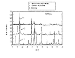
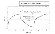
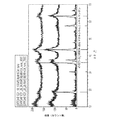
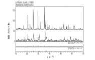
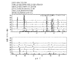
3Vマグネシウムカソード材料の実験的な検証結果を図1と2に示す。図1は一連のXRDスペクトルで、化学的なMg取り出しとMgMn2O4相への電気化学的なMgの再挿入を示している。図2は正方スピネル型MgMn2O4の開始時の充電/放電テストを示している。これらのデータから、約2.7Vで上記スピネルからのマグネシウム電気化学的取出し(反応[1])が開始されることが明らかである。MgMn2O4へのマグネシウム挿入用の電圧計算値である〜1.7Vで、勾配に変化が起こり始めている。この計算は、この相が低電圧反応[2]中にかなり高い拡散障壁を示すことを示唆しており、これは我々とKurihawaらの実験領域で観察された最小限容量に関する説明を与えている。その結果、本願で述べられているスピネル型材料は式[1]で示されるMg抽出反応を行うことができるものを目標にしている。 Experimental verification results of the 3V magnesium cathode material are shown in FIGS. FIG. 1 is a series of XRD spectra showing chemical Mg removal and electrochemical Mg reinsertion into the MgMn 2 O 4 phase. FIG. 2 shows the charge / discharge test at the start of the square spinel MgMn 2 O 4 . From these data, it is clear that magnesium electrochemical removal from the spinel (reaction [1]) is initiated at about 2.7V. At a voltage calculation value of ~ 1.7 V for inserting magnesium into MgMn 2 O 4 , the gradient starts to change. This calculation suggests that this phase exhibits a fairly high diffusion barrier in the low voltage response [2], which gives an explanation for the minimum capacity observed in the experimental area of us and Kurihawa et al. . As a result, the spinel-type material described in the present application is targeted to be capable of performing the Mg extraction reaction represented by the formula [1].
特定の実施形態では、これらスピネル型化合物はCr、V、Fe、Co、Ni、Mnおよびそれらの混合物で構成される群から選択される1つ以上の金属を遷移金属として含む酸化物である。非限定的な例としては、MgCr2O4、MgV2O4、MgFe2O4、MgMg5V4O12、MgCo2O4、MgMn2O4、MgNi2O4、MgCrVO4、MgCrCoO4、MgNiMnO4、MgCoMnO4、MgMnVO4、MgFeNiO4、MgCrNiO4、MgNiVO4、MgCoVO4、Mg3FeV5O12、Mg3MnV5O12、Mg2CrV3O8、Mg2VCr3O8、Mg2FeV3O8、Mg2VFe3O8、Mg3CrV5O12、Mg3Fe2V4O12、Mg3Fe1V5O12、Mg3V1Mn5O12、Mg3Cr2V4O12、Mg3V2Fe4O12、Mg3Cr1V5O12、Mg3Cr4V2O12、Mg3Cr4V2O12、MgFeVO4、MgNiVO4、Mg3Ni2V4O12、Mg2MnV3O8、Mg3Co2V4O12、Mg2NiMn3O8、Mg3NiMn5O12、Mg3Ni2Mn4O12、Mg2NiFe3O8、Mg3Ni1Fe5O12、Mg3Ni2Fe4O12、Mg3Ni1Cr5O12、Mg2NiCr3O8、Mg3Ni2Cr4O12などがある。他の実施形態において、上記スピネル型化合物はZr、V、Mn、Crおよびそれらの混合物で構成される群から選択される1つ以上の金属を含硫化物およびセレン化合物のスピネル型化合物などである。非限定的な例としては、MgZr2S4、MgZr2Se4、MgV2Se4、MgCr2S4、MgCr2Se4、MgMn2S4、MgMn2Se4、MgCrVS4、MgCrVSe4、などがある。いくつかの実施形態において、これらの材料はカソード活性材料として用いられる。その他の実施形態において、これらの材料は低電圧(約0.25Vから約2.5V対Mg/Mg2+)を提供し、マグネシウム挿入アノード活性材料として用いられる。 In certain embodiments, these spinel-type compounds are oxides that include one or more metals selected from the group consisting of Cr, V, Fe, Co, Ni, Mn, and mixtures thereof as a transition metal. Non-limiting examples include MgCr 2 O 4 , MgV 2 O 4 , MgFe 2 O 4 , MgMg 5 V 4 O 12 , MgCo 2 O 4 , MgMn 2 O 4 , MgNi 2 O 4 , MgCrVO 4 , MgCrCoO 4 MgNiMnO 4 , MgCoMnO 4 , MgMnVO 4 , MgFeNiO 4 , MgCrNiO 4 , MgNiVO 4 , MgCoVO 4 , Mg 3 FeV 5 O 12 , Mg 3 MnV 5 O 12 , Mg 2 CrV 3 O 8 Cr, Mg 2 CrV 3 O 8 Mg 2 FeV 3 O 8 , Mg 2 VFe 3 O 8 , Mg 3 CrV 5 O 12 , Mg 3 Fe 2 V 4 O 12 , Mg 3 Fe 1 V 5 O 12 , Mg 3 V 1 Mn 5 O 12 , Mg 3 Cr 2 V 4 O 12 , Mg 3 V 2 Fe 4 O 12 , Mg 3 Cr 1 V 5 O 12 , Mg 3 Cr 4 V 2 O 12 , Mg 3 Cr 4 V 2 O 12 , MgFeVO 4 , MgNiVO 4 , Mg 3 Ni 2 V 4 O 12 , Mg 2 MnV 3 O 8 , Mg 3 Co 2 V 4 O 12 Mg 2 NiMn 3 O 8 , Mg 3 NiMn 5 O 12 , Mg 3 Ni 2 Mn 4 O 12 , Mg 2 NiFe 3 O 8 , Mg 3 Ni 1 Fe 5 O 12 , Mg 3 Ni 2 Fe 4 O 12 , Mg 3 Ni 1 Cr 5 O 12 , Mg 2 NiCr 3 O 8 , Mg 3 Ni 2 Cr 4 O 12 and the like. In another embodiment, the spinel-type compound includes one or more metals selected from the group consisting of Zr, V, Mn, Cr, and mixtures thereof, including a spinel-type compound of a sulfide-containing compound and a selenium compound. . Non-limiting examples include MgZr 2 S 4 , MgZr 2 Se 4 , MgV 2 Se 4 , MgCr 2 S 4 , MgCr 2 Se 4 , MgMn 2 S 4 , MgMn 2 Se 4 , MgCrVS 4 , MgCrVSe 4 , etc. There is. In some embodiments, these materials are used as cathode active materials. In other embodiments, these materials provide a low voltage (from about 0.25 V to about 2.5 V vs. Mg / Mg 2+ ) and are used as magnesium-inserted anode active materials.
スピネル型化合物は様々な方法で合成することができる。いくつかの実施形態においては、スピネル型化合物は固体状態合成で合成することができ、この方法ではMgOかMg(OH)2をMn2O3などのマンガン酸化物と反応させて、MgMn2O4をつくり出す。別の合成ルートは、後で加熱するために細かく分かれた混合物を得るために、溶液(例えば水溶液など)からの上の反応の共沈殿を行うステップを含んでいる。その他の実施形態においては、これらの材料は2段階反応によって合成され、この2段階反応においては、最初に、Mg以外の二価金属を遷移金属の二元化合物とを反応させて、スピネル構造を有しその四面体構造サイト内で非Mg二価金属が好ましい配列になっている中間籠物を形成する。第2のステップではそのプレースホルダー非マグネシウム陽イオンの取り出しとマグネシウムの挿入が行われる。例えば、ZnC2O4・2H2O+V2O5+C→ZnV2O4+2CO2+CO+2H2Oの反応が行われ、その後で、Mg挿入を行って、MgV2O4が形成される。いくつかの実施形態においては、上記2段階反応のための介在物としてCuMn2O4、CuFe2O4、ZnCr2O4、ZnFe2O4などが用いられる。 Spinel compounds can be synthesized by various methods. In some embodiments, spinel compounds can be synthesized by solid state synthesis, in which MgO or Mg (OH) 2 is reacted with a manganese oxide such as Mn 2 O 3 to produce MgMn 2 O. Create 4 Another synthetic route involves performing a coprecipitation of the above reaction from a solution (such as an aqueous solution) to obtain a finely divided mixture for later heating. In other embodiments, these materials are synthesized by a two-step reaction in which a bivalent metal other than Mg is first reacted with a binary compound of a transition metal to form a spinel structure. In the tetrahedral structure site, an intermediate deposit is formed in which the non-Mg divalent metal is in a preferred arrangement. In the second step, the placeholder non-magnesium cation is removed and magnesium is inserted. For example, a reaction of ZnC 2 O 4 .2H 2 O + V 2 O 5 + C → ZnV 2 O 4 + 2CO 2 + CO + 2H 2 O is performed, and then Mg insertion is performed to form MgV 2 O 4 . In some embodiments, CuMn 2 O 4 , CuFe 2 O 4 , ZnCr 2 O 4 , ZnFe 2 O 4 and the like are used as inclusions for the two-stage reaction.
いくつかの実施形態において、MgCr2SとZr、V、MnおよびCrとそれらの混合物を含む硫化物スピネルを、MgSと二元遷移金属硫化物を固体状態合成の条件下で、例えば、MgS+Cr2S3→MgCr2S4の反応を行わせて単一ステップで合成する。他の実施形態においては、これらの材料は2段階反応で合成され、この場合、最初に非Mg二価金属硫化物を固体状態条件下で二元遷移金属硫化物と反応させてスピネル構造と上記非Mg二価金属が正方組織サイトを占有している好ましい配列を有する中間化合物を形成する。2番目のステップでは上記プレースホルダー非Mg二価陽イオンの取り出しと、それに続くマグネシウム挿入が行われる。いくつかの実施形態においては、CuS+Cr2S3→CuCr2S4の反応が行われて、次に、化学的あるいは電気化学的Cu抽出が行われて、その後でMg挿入が行われて、MgCr2S4が形成される。この2段か反応の中間化合物の非限定的な例としては、CuV2S4、ZnCr2S4、CuCo2S4、CuZr2S4、CuCr2S4などがある。 In some embodiments, a sulfide spinel comprising MgCr 2 S and Zr, V, Mn and mixtures thereof and mixtures thereof, MgS and binary transition metal sulfides under conditions of solid state synthesis, eg, MgS + Cr 2 The reaction of S 3 → MgCr 2 S 4 is performed and synthesized in a single step. In other embodiments, these materials are synthesized in a two-step reaction, where a non-Mg divalent metal sulfide is first reacted with a binary transition metal sulfide under solid state conditions to produce the spinel structure and the above. The non-Mg divalent metal forms an intermediate compound having a preferred sequence that occupies a square tissue site. In the second step, the placeholder non-Mg divalent cation is taken out, followed by magnesium insertion. In some embodiments, the reaction CuS + Cr 2 S 3 → CuCr 2 S 4 is performed, followed by chemical or electrochemical Cu extraction, followed by Mg insertion, and MgCr 2 S 4 is formed. Non-limiting examples of intermediate compounds of the 2-step or reaction, and the like CuV 2 S 4, ZnCr 2 S 4, CuCo 2 S 4, CuZr 2 S 4, CuCr 2 S 4.
別の態様で、マグネシウム電池で電極材料として使用するための、化学式Ab’MgaMb(XOz)yで示される化合物について述べるが、この化学式で、
AはAl、Li、Na、K、Zn、Ag、Cuおよびそれらの混合物で構成される群から選択される1つ以上のドーパントであり、
MはTi、V、Cr、Mn、Fe、Co、Ni、Cu、Zr、Nb、Mo、Sn、Sb、Bi、Ta、Wおよびそれらの化合物で構成される群から選択される1つ以上の遷移金属であり、
XはP、V、Si、B、C、As、S、Nおよびそれらの混合物で構成される群から選択される1つ以上の陰イオンであり、
0.9≦b’≦3.9であり、
0 ≦a≦3.1であり、
0.9≦b≦3.9であり、
0.9≦y≦3.9であり、
1.9≦z≦3.9であり、かつ
上記化合物がMgaMnSiO4やMg0.5Ti2(PO4)3でなければ、オリビン構造あるいはNASICON型構造を有しているか、あるいは上記化合物がLiVP2O7構造かバナジウムオキシ−ホスフェートVO(PO4)構造と同型である。
In another aspect, a compound represented by the chemical formula Ab′Mg a M b (XOz) y for use as an electrode material in a magnesium battery is described.
A is one or more dopants selected from the group consisting of Al, Li, Na, K, Zn, Ag, Cu and mixtures thereof;
M is one or more selected from the group consisting of Ti, V, Cr, Mn, Fe, Co, Ni, Cu, Zr, Nb, Mo, Sn, Sb, Bi, Ta, W and their compounds A transition metal,
X is one or more anions selected from the group consisting of P, V, Si, B, C, As, S, N and mixtures thereof;
0.9 ≦ b ′ ≦ 3.9,
0 ≦ a ≦ 3.1,
0.9 ≦ b ≦ 3.9,
0.9 ≦ y ≦ 3.9,
If 1.9 ≦ z ≦ 3.9 and the compound is not Mg a MnSiO 4 or Mg 0.5 Ti 2 (PO 4 ) 3 , it has an olivine structure or NASICON structure, or The compound is of the same type as the LiVP 2 O 7 structure or vanadium oxy-phosphate VO (PO 4) structure.
いくつかの実施形態において、MはTi、V、Cr、Mn、Fe、Co、Ni、Cu、Zr、Nb、Mo、Sn、Sb、Bi、Ta、あるいはWなどの金属陽イオンであり、Xは炭素(C)、ホウ素(B)、リン(Si)、ケイ素(S)、窒素(N)、砒素(As)などの非金属陽イオンである。いくつかの実施形態において、上記化合物はポリアニオン系”XO2”で構成されている。いくつかの実施形態において、この化合物はオリビン構造を有している。別の実施形態においては、上記化合物はNASICON型構造を有している。これらの材料はオリビンタイプの構造、NASICON型タイプの構造、二リン酸塩タイプの構造、あるいはバナジウムオキシ−ホスフェートタイプの構造を有している場合もある。 In some embodiments, M is a metal cation such as Ti, V, Cr, Mn, Fe, Co, Ni, Cu, Zr, Nb, Mo, Sn, Sb, Bi, Ta, or W, and X Is a non-metallic cation such as carbon (C), boron (B), phosphorus (Si), silicon (S), nitrogen (N), arsenic (As). In some embodiments, the compound is composed of the polyanionic system “XO 2 ”. In some embodiments, the compound has an olivine structure. In another embodiment, the compound has a NASICON-type structure. These materials may have an olivine type structure, a NASICON type structure, a diphosphate type structure, or a vanadium oxy-phosphate type structure.
いくつかの実施形態において、b’は0であり、上記化合物は化学式MgaMb(XO2)yで示される組成を有している。 In some embodiments, b ′ is 0 and the compound has a composition represented by the chemical formula Mg a M b (XO 2 ) y .
いくつかの実施形態において、上記化合物は酸化された状態にあり、aは約0である。いくつかの実施形態において、上記化合物は還元された状態にあり、aは約2である。いくつかの実施形態においては、bは約1であり、yは約2である。他の実施形態においては、bや約2であり、yは約3.9である。 In some embodiments, the compound is in an oxidized state and a is about 0. In some embodiments, the compound is in the reduced state and a is about 2. In some embodiments, b is about 1 and y is about 2. In other embodiments, b or about 2 and y is about 3.9.
特定の実施形態においては、b’は0.05≦b’≦2.9の範囲である。特定の実施形態においては、b’は0.05≦b’≦2.0の範囲である。特定の実施形態においては、b’は0.05≦b’≦1.5の範囲である。特定の実施形態においては、b’は0.05≦b’≦1.0の範囲である。特定の実施形態においては、b’は0.1≦b’≦2.0の範囲である。特定の実施形態においては、b’は0.2≦b’≦1.5の範囲である。特定の実施形態においては、aは0≦a≦2の範囲である。特定の実施形態においては、aは0.5≦a≦1.5の範囲である。特定の実施形態においては、aは0.75≦a≦1.25の範囲である。特定の実施形態においては、bは0.5≦a≦2の範囲である。特定の実施形態においては、bは0.75≦a≦1.5の範囲である。特定の実施形態においては、bは0.75≦a≦1.0の範囲である。特定の実施形態においては、aは0.75≦a≦1.25の範囲である。特定の実施形態においては、yは1.0≦y≦3.9の範囲である。特定の実施形態においては、yは1.5≦y≦3.5の範囲である。特定の実施形態においては、yは2.0≦y≦3.0の範囲である。特定の実施形態においては、yは3≦y≦3.5の範囲である。特定の実施形態においては、yは1.0≦y≦2.0の範囲である。特定の実施形態においては、zは2.0≦y≦3.9の範囲である。特定の実施形態においては、yは2.5≦z≦3.5の範囲である。特定の実施形態においては、yは2.5≦z≦3.0の範囲である。特定の実施形態においては、yは3≦z≦3.5の範囲である。a、b、b’、zおよびyのすべての範囲は、上に述べたa、b、b’、zおよびyのいずれとでも組み合わせることができる。
In certain embodiments, b 'is in the range of 0.05≤b'≤2.9. In certain embodiments, b 'is in the range of 0.05≤b'≤2.0. In certain embodiments, b 'is in the range of 0.05≤b'≤1.5. In certain embodiments, b 'is in the range of 0.05≤b'≤1.0. In certain embodiments, b 'is in the range of 0.1≤b'≤2.0. In certain embodiments, b 'is in the range of 0.2≤b'≤1.5. In certain embodiments, a is in the
いくつかの実施形態においては、aが0≦a≦2の範囲である場合に、bは約1、yは約1、そして3≦z≦3.9である。他の実施形態において、aが0≦a≦3の範囲である場合に、bは約2、yは約3、そして3≦z≦3.9である。さらに他の実施形態においては、aが0≦a≦1.53の範囲である場合に、bは約0.5、yは約1、および3≦z≦3.9である。
In some embodiments, when a is in the
いくつかの実施形態においては、ここで述べられている化合物はLiFePO4と同型であり、この構造で、Liサイトは十分に、あるいは部分的にマグネシウムによって占有されており、Feサイトは遷移金属に占有されており、かつPサイトは陽イオンによって占有されている。マグネシウムアノードとこれらの材料で構成されるカソードを含んでいる電池は、市販されているリチウムイオン電池と同等か、あるいはそれより高いエネルギー密度および比エネルギーを有するべきである。 In some embodiments, the compounds described herein are isomorphic to LiFePO 4 , in which the Li site is fully or partially occupied by magnesium and the Fe site is a transition metal. Occupied and the P site is occupied by cations. A battery that includes a magnesium anode and a cathode comprised of these materials should have an energy density and specific energy that is equivalent to or higher than commercially available lithium ion batteries.
いくつかの実施形態においては、マグネシウム電池内で電気活性材料として使用するのに適した特定のオリビン、NASICON型、ニリン酸塩構造、あるいはバナジウムオキシ−ホスフェートタイプの構造を有する化合物が開示される。 In some embodiments, compounds having specific olivine, NASICON, diphosphate, or vanadium oxy-phosphate type structures suitable for use as electroactive materials in magnesium batteries are disclosed.
特定の実施形態においては、マグネシウム電池材料あるいは化合物はオリビン構造のLiFePO4と同型であり、このLiFePO4はFeサイト上にMn、Fe、Co、Ni,Cr、Cuあるいはそれらの混合物を含んでおり、Pサイト上にはP、As、Si、あるいはSを含んでいる。こうした材料あるいは化合物の非限定的な化合物としては、MgFe2(PO4)2、MgCr2(PO4)2、MgMn2(PO4)2、Mg2Mn(PO4)2、Mg3Fe3(PO4)4、MgCo2(PO4)2、Mg3Co3(PO4)4、MgNi2(PO4)2、MgMnFe(PO4)2、、MgMnCo2(PO4)2などがある。オリビン構造の材料は様々な方法で合成することができ、例えば、LiFePO4からLi+を化学的あるいは電気化学的に除去して、その後にFePO4をMgと反応させる方法で合成することができる。これらの方法はLiサイト上にMgを適切な配列で導入することを可能にしてくれる。他の実施形態においては、上記材料はMg−を含有する前駆体から直接の固体状態合成によってつくられる。 In certain embodiments, the magnesium battery material or compound is LiFePO 4 and isomorphic olivine structure, the LiFePO 4 is Mn on the Fe site, Fe, Co, Ni, Cr, includes a Cu or mixtures thereof , P, As, Si, or S is contained on the P site. Non-limiting compounds of such materials or compounds include MgFe 2 (PO 4 ) 2 , MgCr 2 (PO 4 ) 2 , MgMn 2 (PO 4 ) 2 , Mg 2 Mn (PO 4 ) 2 , Mg 3 Fe 3 (PO 4 ) 4 , MgCo 2 (PO 4 ) 2 , Mg 3 Co 3 (PO 4 ) 4 , MgNi 2 (PO 4 ) 2 , MgMnFe (PO 4 ) 2 , MgMnCo 2 (PO 4 ) 2 . The olivine structure material can be synthesized by various methods, for example, by chemically or electrochemically removing Li + from LiFePO 4 and then reacting FePO 4 with Mg. . These methods make it possible to introduce Mg in an appropriate arrangement on the Li site. In other embodiments, the material is made by direct solid state synthesis from precursors containing Mg-.
特定の実施形態においては、上記のマグネシウム材料は菱面体晶あるいは単斜系のNASICON型(Na3Zr2Si2PO12)構造を有しており、この構造では、Zrサイトは少なくとも部分的には遷移金属Ti、V、Cr、Mn、Fe、Co、Ni、Cu、Zr、Nb、Mo、Sn、Sbによって占有されており、SiおよびPサイトはAl、P、Si、VまたはAsで占有されており、OサイトはOによって占められている。マグネシウムはその材料全体で多数の低エネルギーNaサイト上に位置していてもよい。例示的な材料はMg0.5V2(PO4)3、MgV2(PO4)3、Mg0.5Ti2(PO4)3、Mg1.5Cr2(PO4)3などである。いくつかの実施形態においては、ここに述べられている化合物は、ここに述べられている化合物は単斜晶あるいは菱面体晶系のNASICON型単位格子と同型の単位格子原子構成を有している。 In certain embodiments, the magnesium material has a rhombohedral or monoclinic NASICON (Na 3 Zr 2 Si 2 PO 12 ) structure, where the Zr site is at least partially Is occupied by transition metals Ti, V, Cr, Mn, Fe, Co, Ni, Cu, Zr, Nb, Mo, Sn, Sb, and Si and P sites are occupied by Al, P, Si, V or As O sites are occupied by O. Magnesium may be located on a number of low energy Na sites throughout the material. Exemplary materials include Mg 0.5 V 2 (PO 4 ) 3 , MgV 2 (PO 4 ) 3 , Mg 0.5 Ti 2 (PO 4 ) 3 , Mg 1.5 Cr 2 (PO 4 ) 3, etc. is there. In some embodiments, the compound described herein has a unit cell atomic configuration that is the same type as the monoclinic or rhombohedral NASICON unit cell. .
特定の実施形態においては、上記材料はLiVP2O7構造と同型であり、この場合、Liサイトはマグネシウムによって十分に、あるいは部分的に占有されており、PサイトはPによって占有され、OサイトはOで占有されている。特殊な実施形態においては、上記LiVP2O7に基づく構造がTi、V、Cr、Mn、Fe、Mo、あるいはそれらの混合物をVサイト上に含んでいる。 In certain embodiments, the material is isomorphic to the LiVP 2 O 7 structure, where the Li site is fully or partially occupied by magnesium, the P site is occupied by P, and the O site. Is occupied by O. In a special embodiment, the LiVP 2 O 7 based structure includes Ti, V, Cr, Mn, Fe, Mo, or a mixture thereof on the V site.
特定の実施形態においては、上記材料はバナジウムオキシ−ホスフェートVO(PO4)構造と同型である。VO(PO4)はいくつかの多様な構造(アルファ、ベータ、デルタ、オメガ、イプシロン、ガンマ)で見られる公知のオキシ−ホスフェートで、水和状態と脱水状態の両方がある。いくつかの実施形態においては、上記化合物は電気化学的性質とMg移動性を示す構造を有しており、Mg挿入電極として用いられる。バナジウムオキシ−ホスフェート化合物の中では、ベータ型のVOPO4がマグネシウム挿入および除去に関して優れた安定性を示し、その容量も優れていて、最大でバナジウム原子1個あたりマグネシウムイオン1個までの容量を示す。いくつかの実施形態においては、上記化合物はベータ型VOPO4単位格子と同形の単位格子原子構成を有している。いくつかの実施形態においては、では、上記化合物はベータ型VOPO4である。 In certain embodiments, the material is isomorphic to the vanadium oxy-phosphate VO (PO 4 ) structure. VO (PO 4 ) is a known oxy-phosphate found in several diverse structures (alpha, beta, delta, omega, epsilon, gamma) and is both hydrated and dehydrated. In some embodiments, the compound has a structure that exhibits electrochemical properties and Mg mobility and is used as an Mg insertion electrode. Among the vanadium oxy-phosphate compounds, beta-type VOPO 4 exhibits excellent stability with respect to magnesium insertion and removal, and its capacity is excellent, with a capacity of up to one magnesium ion per vanadium atom. . In some embodiments, the compound has a unit cell atomic configuration that is isomorphous to the beta VOPO 4 unit cell. In some embodiments, the compound is beta VOPO 4 .
さらに別の実施形態においては、立体TiP2O7構造を有している金属二リン酸塩化合物内に化学的あるいは電気化学的な方法で、マグネシウムを挿入することができる。非限定的な例としては、TiP2O7およびMoP2O7などがある。VP2O7などのVP2O7構造を有する化合物も立体二リン酸塩の場合よりやや遅い速度でマグネシウムを挿入することができる。二リン酸塩タイプの範囲内で想定される他の化合物としては、Mg0.5TiP2O7、Mg0.5VP2O7、Mg0.5CrP2O7、Mg0.5MoP2O7、Mg1CrP2O7、Mg1MnP2O7、Mg1CoP2O7、Mg1NiP2O7などがある。いくつかの実施形態においては、上記化合物は立体二リン酸塩TiP2O7単位格子と同形の単位格子原子構成を有している。 In yet another embodiment, magnesium can be inserted into the metal diphosphate compound having a steric TiP 2 O 7 structure by chemical or electrochemical methods. Non-limiting examples include TiP 2 O 7 and MoP 2 O 7 . VP 2 O compounds with VP 2 O 7 structure such as 7 may be inserted magnesium a slightly slower rate than the case of the stereoscopic diphosphate. Other compounds envisaged within the range of the diphosphate type include Mg 0.5 TiP 2 O 7 , Mg 0.5 VP 2 O 7 , Mg 0.5 CrP 2 O 7 , Mg 0.5 MoP. 2 O 7 , Mg 1 CrP 2 O 7 , Mg 1 MnP 2 O 7 , Mg 1 CoP 2 O 7 , Mg 1 NiP 2 O 7 and the like. In some embodiments, the compound has a unit cell atomic configuration that is isomorphic to the steric diphosphate TiP 2 O 7 unit cell.
いくつかの特殊な実施形態においては、上記化合物はオリビン構造のMgFe2(PO4)2である。他の特殊な実施形態においては、XはPである。さらに別の特殊な実施形態においては、上記化合物はNASICON型のMgFe2(PO4)3あるいはMgV2(PO4)3である。 In some special embodiments, the compound is olivine-structured MgFe 2 (PO 4 ) 2 . In another special embodiment, X is P. In yet another special embodiment, the compound is NASICON type MgFe 2 (PO 4 ) 3 or MgV 2 (PO 4 ) 3 .
いくつかの実施形態においては、b’は0ではなく、ドーパントAが遷移金属と部分的に置換しており、電極材料の性能とコスト性を向上させてくれる。マグネシウムアノードとこれらの材料で構成されるカソードを含んでいる電池は炭素質挿入アノードを特徴とする現在市販されているリチウムイオン電池と比較して、理論的エネルギー密度と比エネルギーも優れている。
合成方法
In some embodiments, b ′ is not 0 and the dopant A is partially substituted with a transition metal, improving the performance and cost of the electrode material. Batteries containing a magnesium anode and a cathode composed of these materials have superior theoretical energy density and specific energy as compared to currently marketed lithium ion batteries featuring a carbonaceous inserted anode.
Synthesis method
さらに別の態様においては、ここで述べられている1つの化合物を合成する方法を示しており、この方法では、固体状態での合成、共沈殿、あるいはマグネシウム含有前駆体からの炭素熱還元が用いられ、上記のマグネシウム含有前駆体はMgO、Mg(OH)2、MgCO3、MgSO4、MgS、MgF2、MgHPO4、Mg金属、およびそれらの混合物で構成される群から選択される1つ以上の化合物を含んでいる。 In yet another embodiment, a method for synthesizing one of the compounds described herein is shown, which uses solid state synthesis, coprecipitation, or carbothermal reduction from a magnesium-containing precursor. And the magnesium-containing precursor is one or more selected from the group consisting of MgO, Mg (OH) 2 , MgCO 3 , MgSO 4 , MgS, MgF 2 , MgHPO 4 , Mg metal, and mixtures thereof. Of the compound.
いくつかの実施形態においては、一般式として層状MgaMbXy スピネル型MgaMbXy ポリアニオン系MgaMb(XOz)yで示され、Mg電極材料としてここに述べられている材料は、固体状態反応か溶液からの共沈殿のいずれか、あるいは固体前駆体からの炭素熱還元によって、Mg含有前駆体(酸化物、水酸化物、炭酸塩、シュウ酸塩、硫酸塩など)から直接つくられる。例えば、MgMn2O4スピネルは、1MgO(0.403g)と2Mn2O3(1.58g)の固体状態反応などのセラミック法を用いて直接合成することができる。その粉末を最初にすり鉢と乳棒を用いて、あるいは好ましくはシェーカーや平板型ミリングを用いて混合し、その前駆体が完全に分散されるようにする。その後、粉末のまま加熱するか、あるいは好ましくは最初に固体状態での分散を容易にするために微粒子化して、それから大気中、あるいは窒素かアルゴンガス中で500〜700℃の温度で加熱する。上の反応条件を用いると、Mg(OH)2+Mn2O3などのその他のMg前駆体を用いて、MgMn2O4およびH2O蒸気を形成することもできる。他の実施形態において、上記電極材料MgMn2O4は小さな粒子サイズを得るために水溶液からの共沈殿を用いて直接合成される。いくつかの実施形態においては、MgSO4とMnSO4*H2Oが1:2のモル比で水に溶解されて、その溶液を通じて窒素ガスの泡が出ている間に約1モルの上記前駆体の溶液がつくられる。その溶液に、その溶液から泡が出ている間に、濃縮水溶液(約2.5モル溶液)に約4.5モルのNaOHを溶かしたものを滴下して加えて水酸化物を形成する。その後、沈殿物をろ紙に集めて、脱イオン水で洗浄し、その後大気中で50〜100℃(好ましくは70℃)で乾燥する。その後、そのサンプルを300℃から700℃の温度でアニーリングすることで、結晶粒子を成長させることができる。 In some embodiments, the general formula is shown as layered Mg a M b X y spinel-type Mg a M b X y polyanionic Mg a M b (XO z ) y and is described herein as an Mg electrode material. The materials are either Mg-containing precursors (oxides, hydroxides, carbonates, oxalates, sulfates, etc.), either by solid state reaction or coprecipitation from solution, or by carbothermal reduction from solid precursors ) Directly. For example, MgMn 2 O 4 spinel can be synthesized directly using ceramic methods such as solid state reaction of 1MgO (0.403 g) and 2Mn 2 O 3 (1.58 g). The powder is first mixed using a mortar and pestle, or preferably using a shaker or flat milling, so that the precursor is completely dispersed. Thereafter, it is heated as a powder, or preferably first finely divided to facilitate dispersion in the solid state, and then heated in the air or in nitrogen or argon gas at a temperature of 500 to 700 ° C. Using the reaction conditions above, other Mg precursors such as Mg (OH) 2 + Mn 2 O 3 can also be used to form MgMn 2 O 4 and H 2 O vapors. In another embodiment, the electrode material MgMn 2 O 4 is synthesized directly using coprecipitation from an aqueous solution to obtain a small particle size. In some embodiments, MgSO 4 and MnSO 4 * H 2 O are dissolved in water in a molar ratio of 1: 2 and about 1 mole of the precursor is introduced while nitrogen gas bubbles are bubbled through the solution. A body solution is made. While bubbles are emerging from the solution, a solution of about 4.5 mol NaOH in a concentrated aqueous solution (about 2.5 mol solution) is added dropwise to form a hydroxide. Thereafter, the precipitate is collected on a filter paper, washed with deionized water, and then dried at 50 to 100 ° C. (preferably 70 ° C.) in the air. Thereafter, the sample is annealed at a temperature of 300 ° C. to 700 ° C., whereby crystal grains can be grown.
いくつかの実施形態においては、上に述べたようなMg含有スピネル材料の合成中に、時々MgOを純粋な相として得ることができ(酸化物や硫化物などを合成しているかいないかは関係なく)、これは電気的にもイオンとしても極めて絶縁性が高い可能性がある。マグネシウムのスピネル材用を形成するための別の方法は、MgO形成を回避するか、あるいはその可能性を減らすことを目的としている。Mg挿入のためのスピネル材料を形成する方法では、最初に、Cu、Zn、Ag、Li、Na、KあるいはCa形態の材料を合成することが必要で、その後、その材料から(MgまたはLi電池の電極に電気化学的に充電するか、あるいは酸か酸化剤で化学的に抽出するかの方法で)その材料からCu、Zn、Ag、Li、Na、KあるいはCaを抽出して、化学的あるいは電気化学的な手段を用いてMgと置換させることが必要である。いくつかの実施形態においては、ZnSO4およびMnSO4*H2Oの水溶液からの共沈殿を用いてZnMN2O4を合成し、その後、MgO形態を避けるために硝酸を用いて、Znが抽出される。他の実施形態においては、固体状態反応が用いられる。いくつかの特殊な実施形態においては、CuSとCr2S3を不活性気体あるいは密封した容器内で600℃から1000℃の範囲の温度下で反応させて、Cu2Cr2S4スピネルを形成する。その後、Cuを化学的あるいは電気化学的に除去して、Mgを化学的あるいは電気化学的に再挿入する。 In some embodiments, during the synthesis of Mg-containing spinel materials as described above, sometimes MgO can be obtained as a pure phase (regardless of whether oxides, sulfides, etc. are synthesized). Not), which may be very insulating both electrically and ionically. Another method for forming a magnesium spinel material is to avoid or reduce the possibility of MgO formation. In the method of forming a spinel material for Mg insertion, it is first necessary to synthesize a material in the form of Cu, Zn, Ag, Li, Na, K or Ca and then from that material (Mg or Li battery). Cu, Zn, Ag, Li, Na, K, or Ca is extracted from the material by chemical charging of the electrode or by chemical extraction with an acid or oxidizing agent. Alternatively, it is necessary to substitute Mg using electrochemical means. In some embodiments, ZnMN 2 O 4 is synthesized using coprecipitation from an aqueous solution of ZnSO 4 and MnSO 4 * H 2 O, and then extracted with nitric acid to avoid the MgO form. Is done. In other embodiments, solid state reactions are used. In some special embodiments, CuS and Cr 2 S 3 are reacted in an inert gas or sealed vessel at temperatures ranging from 600 ° C. to 1000 ° C. to form Cu 2 Cr 2 S 4 spinel. To do. Thereafter, Cu is chemically or electrochemically removed, and Mg is chemically or electrochemically reinserted.
いくつかの実施形態においては、ここに記載の化合物を合成する方法が開示されており、この方法では、Cu、Zn、Ag、Na、K、Rb、Cd、Ca、Sr、Baおよびそれらの組み合わせで構成される群から選択される1つ以上の金属を含む前駆体を用い、その前駆体内のCu、Zn、Ag、Na、K、Rb、Cd、Ca、Sr、あるいはBaは電気化学的に抽出され、化学的あるいは電気化学的挿入によってMgと置き換えられる。いくつかの特殊な実施形態においては、上に述べた層状あるいはスピネル材料の調製は2段階手順で達成され、その手順においては、層状材料内のMg層の四面体スピネルサイトあるいは八面体体サイト内のMgの場所を占有しているNa、K、Li、Cu、Ag、Zn、Caを用いて合成される。その後、そのスピネルの四面体あるいは層状材料のMg層の八面体サイトからのプレースホルダー陽イオン(Na、K、Li、Cu、Ag、Zn、Ca)を、その中間体を化学酸化剤あるいは酸性溶液(例えば、pH=約1のHCl)に室温で攪拌しながら6〜24時間浸すことによって、化学的に抽出することができる。その後、サンプルを脱イオン水で洗浄して、室温下、減圧状態(10−3Torr)で乾燥するか、あるいは60℃から120℃で大気圧下または減圧状態(10−3Torr)で乾燥する。そして、先ず、上記スピネル材料、伝導性炭素(例えば、スーパーP)、Mg金属カソード、Mg合金カソードあるいは低電圧Mg含有挿入材料を含む電気化学電池に入れられる結合材(例えば、PVdF)、およびMg含有電解質を含む電極を作製することによって、Mgイオンを空いている四面体サイトに挿入する。その後、放電が行われてスピネル構造の空いている四面体サイトにMg挿入が行われるので、ホスト構造にMgが高度に拡散される。あるいは、サンプルを300%超のジブチルマグネシウムをヘプタンに溶かした溶液に入れて20℃から40℃の温度で5日から2週間攪拌することによってもたらされる化学的挿入の方法で、上記スピネル構造の空いている四面体サイトあるいは層状材料の空いているMg八面体サイトにMgイオンが挿入される。 In some embodiments, a method of synthesizing the compounds described herein is disclosed, wherein the method includes Cu, Zn, Ag, Na, K, Rb, Cd, Ca, Sr, Ba, and combinations thereof. A precursor containing one or more metals selected from the group consisting of: Cu, Zn, Ag, Na, K, Rb, Cd, Ca, Sr, or Ba in the precursor is electrochemically Extracted and replaced with Mg by chemical or electrochemical insertion. In some special embodiments, the preparation of the layered or spinel material described above is accomplished in a two-step procedure, in which the Mg layer within the layered material has a tetrahedral spinel site or an octahedral site. It is synthesized using Na, K, Li, Cu, Ag, Zn, and Ca that occupy the Mg location. Then, placeholder cations (Na, K, Li, Cu, Ag, Zn, Ca) from the octahedral site of the spinel tetrahedron or layered material Mg layer, and the intermediate as a chemical oxidant or acidic solution Chemical extraction can be achieved by immersing in (for example, HCl at pH = about 1) at room temperature for 6-24 hours with stirring. Thereafter, the sample is washed with deionized water and dried at room temperature under reduced pressure (10 −3 Torr), or dried at 60 to 120 ° C. under atmospheric pressure or reduced pressure (10 −3 Torr). . And first, a binder (eg, PVdF) that is put into an electrochemical cell that includes the spinel material, conductive carbon (eg, Super P), Mg metal cathode, Mg alloy cathode, or low voltage Mg-containing insert material, and Mg By producing an electrode containing the electrolyte, Mg ions are inserted into the vacant tetrahedral site. Thereafter, discharge is performed and Mg is inserted into empty tetrahedral sites of the spinel structure, so that Mg is highly diffused in the host structure. Alternatively, the spinel structure is emptied by a chemical insertion method which is effected by placing the sample in a solution of more than 300% dibutylmagnesium in heptane and stirring at a temperature of 20 ° C. to 40 ° C. for 5 days to 2 weeks. Mg ions are inserted into open tetrahedral sites or vacant Mg octahedral sites of the layered material.
他の実施形態において、電気活性Mg層状あるいはスピネル材料が合成される。これらの特殊な実施形態においては、四面体スピネルサイトのMgの場所や層状材料の八面体Mgサイトを占有しているNa、K、Li、Cu、Ag、Zn、Caあるいはそれらの混合物を含んだ中間体化合物が電池の電極の電気活性材料として用いられる。この電極は電導性のカーボンブラックとPVdF結合材も含んでいる。この電池はさらに、非水性Liイオン伝導性電解質とLi金属カソードも含んでいる。この電池はプレースホルダー陽イオンを確実に抽出できるようにする電圧(例えばLiLiMn2O4の場合4.3V)に定電流で充電され、約10時間、あるいは荷電容量が理論値(例えば、LiMn2O4の場合に125mAh/gおよび150mAh/g)の80%から100%の範囲になるまで、定電圧状態に保持される。この時点で、上記電池は解体され、炭酸ジメチルか炭酸ジエチルで洗浄されて、残留Li塩が取り除かれる。その後、その電極は室温減圧下(10−3Torr)か、大気圧あるいは減圧状態(10−3Torr)下で60℃から120℃の温度下かのいずれかで乾燥される。Mgイオンはスピネル構造の空になっている四面体サイトか層状材料の空のMg八面体サイトに挿入することができるので、Mg金属カソードあるいは低電圧Mg含有挿入材料およびMg含有電解質を含んだ電気化学的電池内にその電極を入れることで、ホスト構造内での高いMg拡散を可能にしてくれる。その後に放電を行うと、スピネル構造の空になっている四面体サイトか層状材料の空のMg八面体サイトにMgを挿入されるので、ホスト構造内での高いMg拡散が可能になる。あるいは、そのサンプルを300%超のジブチルマグネシウムをヘプタンに溶かした溶液に入れて、20℃から40℃の温度で5日間から2週間攪拌することでMgイオンを挿入することで、スピネル構造の空になっている四面体サイトか層状材料の空のMg八面体サイトにMgイオンを挿入することができる。 In other embodiments, electroactive Mg layered or spinel materials are synthesized. These special embodiments included Na, K, Li, Cu, Ag, Zn, Ca or mixtures thereof occupying the Mg locations of the tetrahedral spinel sites and the octahedral Mg sites of the layered material. Intermediate compounds are used as electroactive materials for battery electrodes. The electrode also includes conductive carbon black and PVdF binder. The battery further includes a non-aqueous Li ion conducting electrolyte and a Li metal cathode. This battery is charged at a constant current to a voltage (eg, LiVnMn 2 O 4 in the case of LiVnMn 2 O 4 ) that ensures extraction of placeholder cations, and is charged for about 10 hours or a theoretical value (eg, LiMn 2 In the case of O 4 , it is maintained at a constant voltage state until it is in the range of 80% to 100% of 125 mAh / g and 150 mAh / g). At this point, the battery is disassembled and washed with dimethyl carbonate or diethyl carbonate to remove residual Li salt. The electrode is then dried either at room temperature under reduced pressure (10 −3 Torr) or at a temperature of 60 ° C. to 120 ° C. under atmospheric pressure or reduced pressure (10 −3 Torr). Mg ions can be inserted into the empty tetrahedral site of the spinel structure or into the empty Mg octahedral site of the layered material, so that the Mg metal cathode or the low-voltage Mg-containing insertion material and the Mg-containing electrolyte are included. Placing the electrode in a chemical cell allows high Mg diffusion in the host structure. When discharging is subsequently performed, Mg is inserted into the empty tetrahedral site of the spinel structure or the empty Mg octahedral site of the layered material, so that high Mg diffusion in the host structure becomes possible. Alternatively, the spinel structure is emptied by inserting Mg ions by placing the sample in a solution of over 300% dibutylmagnesium in heptane and stirring at a temperature of 20 ° C. to 40 ° C. for 5 days to 2 weeks. Mg ions can be inserted into the tetrahedral site or the empty Mg octahedral site of the layered material.
いくつかの実施形態において、Mg含有前駆体の直接合成から、様々なタイプのMg含有多価陽イオン電極材がつくられる。他の実施形態においては、2段階の手順でMg含有ポリアニオン系電極材がつくられ、この手順では、Mgサイトを占有しているCu、Zn、Ag、Li、Na、KあるいはCaを用いて、中間体化合物がつくられる。その後、プレースホルダー陽イオン(例えば、Cu、Zn、Ag、Li、Na、KあるいはCaなど)を化学的あるいは電気化学的に取り除き、Mgが化学的あるいは電気化学的に空になっているサイトに挿入される。いくつかの実施形態においては、二価マグネシウムおよび二価遷移金属から形成されるオリビン構造あるいはその他のポリアニオン系が、それら陽イオンの等電荷性の故に意図されたMgサイトと上記二価遷移金属間に高度の混合をもたらす。そうした混合はホスト構造内でのMg分散を相当程度抑制する可能性がある。例えば、Mg1.03Mn0.97SiO4へのMg挿入に関するNuliらによる研究は、サイトにかなりの無秩序があって(彼らの研究では8−11%)、そのことがこの材料の理論的容量の1/2以下しかMg挿入を可能にしていないことを示している。この格子サイトへのこれら陽イオンの分離を誘発するために一価のLi、Na、J、Cu、Agを用いると、そうした問題が発生する可能性を引き下げてくれる。一般的に、Mg2+、M2+および(SiO4)2−のオリビン構造を形成するためにMg含有前駆体を用いると、その他のオキシ陰イオン材料(例えば、リン酸塩、ヒ酸塩、硫酸塩)を形成する場合と比較して、等電荷性混合がより高いレベルで起きる可能性がある。 In some embodiments, various types of Mg-containing multivalent cation electrode materials are made from direct synthesis of Mg-containing precursors. In another embodiment, the Mg-containing polyanionic electrode material is produced in a two-step procedure, and in this procedure, Cu, Zn, Ag, Li, Na, K or Ca occupying the Mg site is used. Intermediate compounds are made. After that, placeholder cations (for example, Cu, Zn, Ag, Li, Na, K, Ca, etc.) are removed chemically or electrochemically, and the Mg is chemically or electrochemically emptied. Inserted. In some embodiments, an olivine structure or other polyanion system formed from divalent magnesium and a divalent transition metal is used between the intended Mg site and the divalent transition metal due to the isocharged nature of the cations. To bring a high degree of mixing. Such mixing can significantly suppress Mg dispersion in the host structure. For example, Nuli et al.'S work on Mg insertion into Mg 1.03 Mn 0.97 SiO 4 has significant site disorder (8-11% in their work), which is the theoretical This shows that Mg can be inserted only to 1/2 or less of the capacity. The use of monovalent Li, Na, J, Cu, Ag to induce the separation of these cations into the lattice sites reduces the possibility of such problems. In general, when Mg-containing precursors are used to form the olivine structure of Mg 2+ , M 2+ and (SiO 4 ) 2− , other oxyanionic materials (eg, phosphate, arsenate, sulfuric acid Compared to the formation of (salt), isoelectric mixing may occur at a higher level.
同様に、Makinoら(J.Power Source 112,85−89,2002)によって研究されたMg0.5Ti2(PO4)3のNASICON型構造は、いくつかのMgタッピングによる限定的なMg移行に対応するFeあるいはCrによるTiの置換によってその材料を作成した場合の格子構造(および単位電池容量)における微妙な変化を示している。いくつかの実施形態においては、ここで述べられている2段階手順を用いて調製された場合には、ある種のNASICON型材料はより好ましい格子パラメータを示すが、この手順においてはそのプレースホルダー陽イオンがMgサイトを占有しているLi、Na、K、Cu、Zn、Ag化合物の中間体合成を必要とする。その後で、これらプレースホルダー陽イオンが化学的あるいは電気化学的に取り除かれて、Mgが前のパラグラフで述べたように化学的あるいは電気化学的に挿入される。いくつかの特殊な実施形態においては、Li−チタンNASION構造がMg−チタンNasiconと比較してやや大きめな電池容量を示す(Li1Ti2(PO4)3の場合は226.27Å3であり、Mg0.5Ti2(PO4)3の場合は225.86)。従って、Li化合物がつくられ、次にLiがMgと置換されて、直接に合成されたMg化合物より有利なMg移動性を有する化合物が得られる。反対の例として、これまでMg挿入電極としての使用については報告されていないMgバナジウムNASICONは、それをMg含有前駆体から直接つくった場合はLi含有前駆体からつくった場合と比較してやや大きな単位電池容量を示す(Li1V2(PO4)3の場合は217.50Åであるのに対して、Mg0.5V2(PO4)3の場合は221.79)。このことは、Li(あるいは他の二番目に好ましい陽イオン類の1つ)以外のMg含有前駆体からの直接合成が必ずしもMg移動性に大きな違いをもたらすものではないことを示唆している。
マグネシウムイオン電池を作成する方法
Similarly, the NASICON-type structure of Mg 0.5 Ti 2 (PO 4 ) 3 studied by Makino et al. (J. Power Source 112, 85-89, 2002) is limited Mg migration due to some Mg tapping. 3 shows a subtle change in the lattice structure (and unit cell capacity) when the material is prepared by replacing Ti with Fe or Cr corresponding to. In some embodiments, certain NASICON-type materials exhibit more favorable lattice parameters when prepared using the two-step procedure described herein, but in this procedure the placeholder explicit Intermediate synthesis of Li, Na, K, Cu, Zn, Ag compounds in which ions occupy Mg sites is required. These placeholder cations are then removed chemically or electrochemically and Mg is inserted chemically or electrochemically as described in the previous paragraph. Some in a special embodiment, in the case of Li- titanium NASION structure compared to the Mg- titanium Nasicon showing a slightly larger battery capacity (Li 1 Ti 2 (PO 4 ) 3 is 226.27A 3, In the case of Mg 0.5 Ti 2 (PO 4 ) 3 225.86). Therefore, a Li compound is produced, and then Li is replaced with Mg, thereby obtaining a compound having Mg mobility more advantageous than the directly synthesized Mg compound. As an opposite example, Mg vanadium NASICON, which has not been reported for use as an Mg insertion electrode, has a slightly larger unit when made directly from an Mg-containing precursor than when made from a Li-containing precursor. The battery capacity is shown (in the case of Li1V 2 (PO 4 ) 3 217.50 Å, whereas in the case of Mg 0.5 V 2 (PO 4 ) 3 221.79). This suggests that direct synthesis from Mg-containing precursors other than Li (or one of the other second most preferred cations) does not necessarily make a significant difference in Mg mobility.
How to make a magnesium ion battery
さらに別の態様で、マグネシウム電池用の電極について述べるが、この電極は本明細書で述べているようなAb’MgaMbXyあるいはAb’MgaMb(XOz)yの化学式で示される化合物を含んでいる。いくつかの実施形態において、Ab’MgaMbXyで示される化合物は非層状VS2、スピネル型Co3O4、層状V2O5、岩塩型MnO、スピネル型Mn2O4、あるいは層状ZrS2である。いくつかの実施形態において、これらの化合物はカソード活性材料として用いられる。いくつかの実施形態においては、これらの化合物は層状構造を有している。他の実施形態においては、これらの化合物はスピネル構造を有している。 In yet another aspect, the described electrodes for the magnesium battery, the electrode A b as described herein 'Mg a M b X y or A b' Mg a M b ( XO z) of y It contains a compound represented by the chemical formula. In some embodiments, the compound represented by A b ′ Mg a M b X y is non-layered VS 2 , spinel-type Co 3 O 4 , layered V 2 O 5 , rock salt-type MnO, spinel-type Mn 2 O 4 , or a layered ZrS 2. In some embodiments, these compounds are used as cathode active materials. In some embodiments, these compounds have a layered structure. In other embodiments, these compounds have a spinel structure.
いくつかの実施形態においては、これらの電極はさらに電導性の添加物を含んでいる。その電導性の添加物非限定的な例はカーボンブラックなどである。いくつかの実施形態においては、上記電極はさらに結合材を含んでいる。結合材の非限定的な例としては、フッ化ポリビニリデン、およびそのターポリマーやコポリマーなどである。 In some embodiments, these electrodes further include a conductive additive. Non-limiting examples of the conductive additive are carbon black and the like. In some embodiments, the electrode further includes a binder. Non-limiting examples of binders include polyvinylidene fluoride and its terpolymers and copolymers.
いくつかの実施形態においては、アノードとしてMg金属あるいはMg合金が用いられ、その結果として、リチウム挿入電池と比較して、容積および重量を基準としてのエネルギー密度がかなり増大する。電気自動車で用いる場合には重量を基準としたエネルギー量が重要であるが、大型の電池パックや携帯用電子機器用の小型の電池パックにとっては、容積基準のエネルギー量の方がより重大な関心事になりつつある。マグネシウムの高容量とMg金属あるいはMg合金カソードの理容はエネルギー密度を1600Wh/lにまで近づけさせることができるので、このことはマグネシウム電池を現段階で利用できる最高のエネルギー密度を提供する技術とするであろう。さらに、種々の原材料資源からマグネシウムを簡単に入手できるので、生産技術を大幅に引き下げることができる。 In some embodiments, Mg metal or Mg alloy is used as the anode, resulting in a significant increase in energy density on a volume and weight basis as compared to a lithium insertion battery. When used in electric vehicles, the amount of energy based on weight is important, but for large battery packs and small battery packs for portable electronic devices, volume-based energy amounts are of greater interest. It is becoming a thing. The high capacity of magnesium and the barge of Mg metal or Mg alloy cathodes can bring the energy density close to 1600 Wh / l, which makes the magnesium battery a technology that provides the highest energy density available at this stage. Will. Furthermore, since magnesium can be easily obtained from various raw material resources, production technology can be greatly reduced.
マグネシウム塩を適切な溶媒に溶解することで、非水性電極溶液がつくられる。マグネシウム塩の例としては、MgCl2、Mg(ClO4)2、Mg(SO2CF3)2、Mg(BF4)2、Mg(CF3SO3)2、およびMg(PF6)2などがある。非水性溶媒の例としては、炭酸プロピレン、炭酸エチレン、炭酸ブチレン、炭酸ビニレン、ガンマ−ブチルラクトーン、スルフォン酸塩、1,2−ジメトキシエタン、1,2−ジエトキシエタン、2−メチルテトラヒドロフラン、3−メチル−1,3−ジオキソラン、プロピオン酸メチル、メチルブチレート、炭酸ジメチル、炭酸ジエチル、および炭酸ジプロピルなどがある。上に述べた非水性溶媒は単独で用いることもできるし、混合して使用することもできる。電気的な安定性を実現する観点からすれば、環状炭酸エステルや鎖状炭酸化合物を用いるのが好ましい。他の例で、上記非水性電解質溶液全体あるいはその一部を有機マグネシウム複合体溶液で構成してもよい。そうした溶液は上に述べたような例示的な溶媒の1つに有機性リガンドとハロゲン化合物の両方が溶解するように調整された、マグネシウムを含むグリニャール化合物から形成される。そうした有機性リガンドの例示的な例としては、アキル、アリル、アルケニル、ヘテロアリル、あるいはn−ジブチル基などがあり、ハロゲン化合物の例としてはF、Cl、Br、Iなどがある。いくつかの例で、そうした化合物は上に述べた例示的な溶媒の1つにおいて、AlBr3、AlCl3、BCl3、FeCl3、FeBr3、TiCl4、SnCl4などの強ルイス酸と錯体を形成している。 A non-aqueous electrode solution is made by dissolving the magnesium salt in a suitable solvent. Examples of magnesium salts include MgCl 2 , Mg (ClO 4 ) 2 , Mg (SO 2 CF 3 ) 2 , Mg (BF 4 ) 2 , Mg (CF 3 SO 3 ) 2 , and Mg (PF 6 ) 2. There is. Examples of non-aqueous solvents are propylene carbonate, ethylene carbonate, butylene carbonate, vinylene carbonate, gamma-butyl lactone, sulfonate, 1,2-dimethoxyethane, 1,2-diethoxyethane, 2-methyltetrahydrofuran, 3 -Methyl-1,3-dioxolane, methyl propionate, methyl butyrate, dimethyl carbonate, diethyl carbonate, and dipropyl carbonate. The non-aqueous solvents mentioned above can be used alone or in combination. From the viewpoint of realizing electrical stability, it is preferable to use a cyclic carbonate or a chain carbonate. In another example, the whole or part of the non-aqueous electrolyte solution may be composed of an organomagnesium complex solution. Such a solution is formed from a Grignard compound containing magnesium, adjusted to dissolve both the organic ligand and the halogen compound in one of the exemplary solvents as described above. Illustrative examples of such organic ligands include acryl, allyl, alkenyl, heteroallyl, or n-dibutyl groups, and examples of halogen compounds include F, Cl, Br, and I. In some examples, such compounds are complexed with strong Lewis acids such as AlBr 3 , AlCl 3 , BCl 3 , FeCl 3 , FeBr 3 , TiCl 4 , SnCl 4 in one of the exemplary solvents described above. Forming.
さらに別の態様で、エネルギー保存装置が述べられており、このエネルギー保存装置はここで述べられているようなMgaMbXyあるいはMgaMb(XO2)yの化学式で示される化合物で構成される第1の正電極と、そしてマグネシウム金属、マグネシウム合金あるいはここに述べられているMgaMbXyあるいはMgaMb(XO2)yの化学式で示される化合物で構成される第2の電極で構成されている。 In yet another aspect, an energy storage device is described, wherein the energy storage device is a compound represented by the formula Mg a M b X y or Mg a M b (XO 2 ) y as described herein. And a magnesium metal, a magnesium alloy, or a compound represented by the chemical formula Mg a M b X y or Mg a M b (XO 2 ) y described herein. It consists of a second electrode.
いくつかの実施形態においては、このエネルギー保存装置はMg電池である。いくつかの特殊な実施形態においては、上記Mg電池は以下の様に作成することができる。ここで述べられている材料から選択される適切なMgカソード材料をカーボンブラック、黒鉛、あるいはその他の電導性炭素および結合材と組み合わせて、不均一な混合物を形成する。上記正電極を望ましい形状にプレスおよび/または成型加工するか、あるいは電流コレクタ上に押し出し加工する。 In some embodiments, the energy storage device is a Mg battery. In some special embodiments, the Mg battery can be made as follows. A suitable Mg cathode material selected from the materials described herein is combined with carbon black, graphite, or other conductive carbon and binder to form a heterogeneous mixture. The positive electrode is pressed and / or molded into the desired shape, or extruded onto a current collector.
上記負電極、通常はMg金属、Mg合金、あるいはここで述べられている材料から選択される第2の電極と上記正電極を、電池容器内で、通常はポリプロピレン製の多孔性薄膜でできているセパレータ上に向き合わせて配置する。上記非水性電解液をその電池容器内に入れて、例えば、圧接によって密封する。 The negative electrode, usually a Mg metal, a Mg alloy, or a second electrode selected from the materials described herein and the positive electrode are made in a battery container, usually a porous thin film made of polypropylene. Place them facing each other on the separator. The non-aqueous electrolyte is put in the battery container and sealed by, for example, pressure welding.
いくつかの実施形態においては、上記負電極と上記正電極を再度電池に入れる場合もある。この電池容器は、缶や積層形状や積層板、ロール形状などを含め種々の標準的な形状を取ることができる。上記セパレータは上記負電極と上記正電極の間に配置され、新しい非水性電解液がその電池容器内に入れられて、圧接封入することができる。 In some embodiments, the negative electrode and the positive electrode may be reinserted into the battery. The battery container can take various standard shapes including cans, laminated shapes, laminated plates, roll shapes, and the like. The separator is disposed between the negative electrode and the positive electrode, and a new non-aqueous electrolyte can be placed in the battery container and sealed in pressure contact.
ターゲット材料に対するアブイニシオ法の結果の一覧(表1)
表1は、多数のマグネシウム含有化合物の組成、構造、および算出された特性をまとめたものである。表中の化合物は、関係する化学に応じてハバード補正項(GGA+U)を伴うか伴わない一般化勾配近似法(GGA)を使用した密度汎関数理論の枠組みを用いて計算された、妥当な反応電圧およびマグネシウム移動度を提供するのに必要な構造と組成を示している。表1に示す移動障壁は、Mg2+イオンが化合物の単位格子を完全に横切るための最小の活性化障壁を表す。活性化障壁とは、2つの別個のMg結晶学的サイト間のエネルギー差と定義され、イラスティックバンド(elastic band)計算により算出される。この計算方法の詳細説明と精度は、[G.Mills,H.Jonsson,and G.K.Schenter,Surf.Sci.324,305,1995.]に記載されている。障壁が800meVより低い物質は、トポタクティック(topotactic)なMg挿入脱離の有用な速度を示すと予測される物質に該当する。さらに、次のような、マグネシウム脱離(de−magged)状態の式MbXyのカソード化合物とのMg挿入反応を検討する。
MbXy+aMg→MgaMbXy [3]
List of Abinitio results for target materials (Table 1)
Table 1 summarizes the composition, structure, and calculated properties of a number of magnesium-containing compounds. The compounds in the table are valid responses calculated using a density functional theory framework using generalized gradient approximation (GGA) with or without Hubbard correction terms (GGA + U) depending on the chemistry involved. It shows the structure and composition needed to provide voltage and magnesium mobility. The migration barrier shown in Table 1 represents the minimum activation barrier for Mg 2+ ions to completely traverse the compound unit cell. The activation barrier is defined as the energy difference between two separate Mg crystallographic sites and is calculated by an elastic band calculation. The detailed explanation and accuracy of this calculation method are described in [G. Mills, H.M. Jonsson, and G. K. Schenter, Surf. Sci. 324, 305, 1995. ]It is described in. Substances with barriers below 800 meV fall under the category of substances that are expected to exhibit a useful rate of topological Mg insertion / extraction. Further, consider the Mg insertion reaction with the cathode compound of formula M b X y in the de-magged state as follows.
M b X y + aMg → Mg a M b X y [3]
Mg挿入反応における平均電圧の計算には、出発化合物の状態(MbXy)、挿入された化合物の状態(MgaMbXy)、およびMg金属状態の基底状態緩和計算を用いる。次に、次式に従って電圧(表1の一覧に示す電圧)を計算できる。
V=(E(MgaMbXy)−E(MbXy))/(aE(Mg)) [4]
式中、Eは、密度汎関数法により算出された基底状態の総エネルギーを表す[M.K.Aydinol,A.F.Kohan,and G.Ceder in Ab Initio Calculation of the Intercalation Voltage of Lithium Transition Metal Oxide Electrodes for Rechargeable Batteries,Elsevier Science Sa,New York,1997,pp.664−668]。表中の電圧は、対Mg 0.5V約対Mg 3.75Vの範囲に対応しており、各種物質が複数の物質カテゴリー(本仕様書ではポリアニオン系化合物、層状化合物、スピネル型化合物に分類)に由来することを示している。予測手法の精度については、Zhouら[F.Zhou,M.Cococcioni,C.A.Marianetti,D.Morgan,G.Ceder,Physical Review,B 70(2004)235121]、Jainら[Jain et al,Computational Materials Science,50,2295−2310,2011]等の多くの出版物で確認されている。

V = (E (Mg a M b X y) -E (M b X y)) / (aE (Mg)) [4]
In the equation, E represents the total energy of the ground state calculated by the density functional method [M. K. Aydinol, A.M. F. Kohan, and G.H. Ceder in Ab Initiation of the Intercalation Voltage of Lithium Transition Metal Oxide Electrodes for Rechargeable Batteries, Eleven Sciencep. 19 664-668]. The voltage in the table corresponds to the range of about 0.5V to Mg and about 3.75V to Mg, and various substances are classified into multiple substance categories (in this specification, classified into polyanion compounds, layered compounds, and spinel compounds) It is derived from. For the accuracy of the prediction method, see Zhou et al. [F. Zhou, M .; Cococcioni, C.I. A. Marianetti, D.M. Morgan, G.M. It has been confirmed in many publications such as Ceder, Physical Review, B 70 (2004) 235121], Jain et al. [Jain et al, Computational Materials Science, 50, 2295-2310, 2011].
スピネル構造の合成の説明
実施例2a.MgMn2O4とMgNiMnO4の共沈法
本実施例は、マグネシウムに対する低拡散経路を有する、高移動度化合物の合成を実証するものであり、以下の反応に従った水酸化物塩の共沈の後に低温のか焼工程を行う、新しい合成法を開発した。
MgSO4(aq)+2MnSO4(aq)+(過剰量)NaOH(aq)→Mg(OH)2(s)+Mn(OH)2(s)+Na2SO4(aq)(25℃) [5]
Mg(OH)2(s)+2Mn(OH)2(s)→nano−MgMn2O4(300℃/8時間) [6]
Description of the synthesis of the spinel structure Example 2a. Example 2 Coprecipitation of MgMn 2 O 4 and MgNiMnO 4 This example demonstrates the synthesis of a high mobility compound having a low diffusion path for magnesium and coprecipitates hydroxide salts according to the following reaction: A new synthesis method has been developed, which is followed by a low-temperature calcination process.
MgSO 4 (aq) +2 MnSO 4 (aq) + (excess) NaOH (aq) → Mg (OH) 2 (s) + Mn (OH) 2 (s) + Na 2 SO 4 (aq) (25 ° C.) [5]
Mg (OH) 2 (s) + 2Mn (OH) 2 (s) → nano-MgMn 2 O 4 (300 ℃ / 8 hours) [6]
代表的な合成では、2.40gのMgS04と6.75gのMnSO4.H2Oを、500mlの三角フラスコ内に入れた100mlのHPLC水に室温で溶かした。次いで、室温で連続的に撹拌しながら、200mlの1M NaOH水溶液を15分かけて滴下によりゆっくり添加した。この苛性添加物によりすぐに茶色の沈殿物が形成されるため、添加中、溶液を連続的に撹拌して、凝集形成を最小化することが肝要であった。撹拌プレート上で溶液と生成物の撹拌を24時間続けて、反応を確実に完了させた。茶色の沈殿物を遠心分離(2000rpm/15分)により単離し、すすぎ液がPh紙で中性になるまで数回水ですすいで沈殿物をまとめた。次に、ナノ−MgMn2O4粉末を100℃で2時間、真空乾燥した。最後に、結晶化の進行とサンプルの純度を示すため、マッフル炉において、真空乾燥した粉末を数種類の温度(300℃、500℃、および750℃)で焼き鈍しした。図3は、適用した合成経路から得たX線回折スペクトルであり、本方法から純相のナノ微結晶(20〜25nm)MgMn2O4物質が得られることが確認される。本明細書に記載の他の化合物に対して、水酸化物塩の共沈により高移動度Mg化合物を得る類似の合成方法を創出した。例えば、以下の反応に従い、同様の方法でスピネル型MgNiMnO4が作製される。
MgSO4(aq)+2MnSO4(aq)+NiSO4(aq)+xsNaOH(aq)→Mg(OH)2(s)+Mn(OH)2(s)+Ni(OH)2(s)+Na2SO4(aq)(25℃) [7]
Mg(OH)2(s)+Mn(OH)2(s)+Ni(OH)2(s)→”MgNiMnO4”−ナノ(300℃/6時間) [8]
In a typical synthesis, 2.40 g MgSO 4 and 6.75 g MnSO 4 . H 2 O was dissolved in 100 ml HPLC water in a 500 ml Erlenmeyer flask at room temperature. Then, with continuous stirring at room temperature, 200 ml of 1M NaOH aqueous solution was slowly added dropwise over 15 minutes. Since this caustic additive quickly forms a brown precipitate, it was important to continuously stir the solution during the addition to minimize aggregate formation. Stirring the solution and product on a stir plate continued for 24 hours to ensure complete reaction. The brown precipitate was isolated by centrifugation (2000 rpm / 15 minutes) and rinsed several times with water until the rinse was neutral on Ph paper, and the precipitate was collected. Next, the nano-MgMn 2 O 4 powder was vacuum-dried at 100 ° C. for 2 hours. Finally, in order to show the progress of crystallization and the purity of the sample, the vacuum-dried powder was annealed at several temperatures (300 ° C., 500 ° C., and 750 ° C.) in a muffle furnace. FIG. 3 is an X-ray diffraction spectrum obtained from the applied synthesis route, and it is confirmed that a pure-phase nanocrystallite (20 to 25 nm) MgMn 2 O 4 substance can be obtained from this method. Similar synthesis methods have been created for other compounds described herein to obtain high mobility Mg compounds by coprecipitation of hydroxide salts. For example, spinel-type MgNiMnO 4 is produced by the same method according to the following reaction.
MgSO 4 (aq) +2 MnSO 4 (aq) + NiSO 4 (aq) + xsNaOH (aq) → Mg (OH) 2 (s) + Mn (OH) 2 (s) + Ni (OH) 2 (s) + Na 2 SO 4 (aq ) (25 ℃) [7]
Mg (OH) 2 (s) + Mn (OH) 2 (s) + Ni (OH) 2 (s) → "MgNiMnO 4" - Nano (300 ℃ / 6 hours) [8]
その後、目的の化合物であるスピネル型MgNiMnO4が確認されることを図4に示す。 Then, it is shown in FIG. 4 that spinel type MgNiMnO 4 which is the target compound is confirmed.
実施例2b.ZnCr2S4の固相合成
他の化学分類のスピネル構造も、Mg電極活物質で使用する材料用として作製した。以下の反応に従い、化学量論量のZnS粉末(0.655g)とCr2S3(1.345g)粉末を使用して、固相反応法により硫化亜鉛クロムを合成した。
ZnS+Cr2S3→ZnCr2S4 900℃/12時間/アルゴン/チューブ炉 [9]
Example 2b. Solid phase synthesis of ZnCr 2 S 4 Other chemical classes of spinel structures were also made for materials used in Mg electrode active materials. According to the following reaction, zinc sulfide chromium was synthesized by a solid phase reaction method using stoichiometric amounts of ZnS powder (0.655 g) and Cr 2 S 3 (1.345 g) powder.
ZnS + Cr 2 S 3 → ZnCr 2 S 4 900 ° C./12 hours / argon / tube furnace [9]
混合物をペレット化してチューブ炉内に入れ、12時間アルゴン流下に置いた。XRD解析では、図5に示すように、生成物は比較的純相のZnCr2S4(>95%)であることを示した。当該技術分野の専門知識を有する者であれば、このような手法を用いて各種の高移動度スピネル型物質が合成されることを想定できる。 The mixture was pelletized and placed in a tube furnace and placed under a stream of argon for 12 hours. XRD analysis indicated that the product was relatively pure phase ZnCr 2 S 4 (> 95%), as shown in FIG. Those skilled in the art can assume that various high mobility spinel materials are synthesized using such a technique.
MgMn2O4(スピネル型酸化マグネシウムマンガン)の化学的Mg脱離、MgMn2O4の化学電気的Mg脱離
本実施例は、Mg含有化合物を作製し、かつ化学的または電気化学手段によりトポタクティックにMgを脱離できることを表す典型例である。図1は、スピネル型MgMn2O4のX線回折(XRD)スペクトルであり、1つ以上の実施形態による、(1)Mgの化学的抽出、および(2)それに次ぐマグネシウムの電気化学的挿入を実証している。この図は、スピネル型MgMn2O4のサンプルに対応するX線回折スペクトルである。このサンプルは、合成後に酸に浸漬してMgを除去し、次いで、サンプルを電気化学試験セルに入れ、電気化学的にMgを再挿入したものである。図2は、電気化学試験セル内のスピネル型MgMn2O4に対応する電圧プロファイルであり、スピネル構造に追加のMgを挿入して、低電圧で岩塩型関連化合物の形成を試みる場合と比べて、スピネル型MgMn2O4の四面体サイトから高電圧で電気化学的にMgを抽出した方が、高い活性が観察されることを実証している。
MgMn 2 O 4 (spinel-type magnesium manganese oxide) chemical Mg desorption, MgMn 2 O 4 chemo-electric Mg desorption This example produces a Mg-containing compound and is topologically produced by chemical or electrochemical means. It is a typical example showing that Mg can be desorbed tactically. FIG. 1 is an X-ray diffraction (XRD) spectrum of spinel MgMn 2 O 4 , according to one or more embodiments: (1) chemical extraction of Mg and (2) subsequent electrochemical insertion of magnesium. Has been demonstrated. This figure is an X-ray diffraction spectrum corresponding to a sample of spinel type MgMn 2 O 4 . This sample was immersed in acid after synthesis to remove Mg, then the sample was placed in an electrochemical test cell and electrochemically reinserted with Mg. FIG. 2 is a voltage profile corresponding to spinel-type MgMn 2 O 4 in an electrochemical test cell, as compared to the case where additional Mg is inserted into the spinel structure to attempt formation of a rock salt-type related compound at a low voltage. It has been demonstrated that high activity is observed when Mg is extracted electrochemically at a high voltage from a tetrahedral site of spinel-type MgMn 2 O 4 .
ポリアニオンの合成:リン酸リチウム鉄(LFP)→化学的に脱リチオ化されたLFP
式5、6に詳述する2段階の反応に従って、リン酸リチウム鉄を作製した。
Li2CO3+Fe(C2O4).2H2O+NH4H2PO4→’機械化学的に反応した前駆体混合物’ 式5
条件:1)12時間、室温でアセトンにおいてボールミル粉砕、次いで2)アセトンをデカント/除去
’前駆体混合物’→LiFePO4+H2O+N2/H2(g)+COx(g)
[10]
条件:350℃/10時間/アルゴンで焼き鈍し、次いで2)600℃/10時間/アルゴンでか焼
Synthesis of polyanions: lithium iron phosphate (LFP) → chemically delithiated LFP
Lithium iron phosphate was prepared according to a two-step reaction detailed in Equations 5 and 6.
Li 2 CO 3 + Fe (C 2 O 4). 2H 2 O + NH 4 H 2 PO 4 → 'Mechanochemically reacted precursor mixture' Formula 5
Conditions: 1) ball milling in acetone at room temperature for 12 hours, then 2) decanting / removing acetone 'precursor mixture' → LiFePO 4 + H 2 O + N 2 / H 2 (g) + COx (g)
[10]
Conditions: 350 ° C./10 hours / annealed with argon, then 2) 600 ° C./10 hours / argon calcinated
第1段階で機械化学的工程により前駆体混合物を得た後、第2段階で前駆体混合物物質を2つの温度で焼き鈍しする。標準的な実施例では、0.937gのLi2CO3、4.10gのFeC2O4.2H2O、および2.77gのNH4H2PO4をあらかじめ混合し、500mlのプラスチック容器に入れた。直径2mm、3mm、および10mmのZrO2ボールメディアと共に、約200mlのアセトンをプラスチック容器に加える。次いで、材料の入った容器をローリングミル上に置き、室温で12時間粉砕した。機械化学的に得た前駆体混合物をまとめるため、アセトンを加熱してデカントと除去の両方を行った。次に、残留する揮発性成分を除去するため、生成物をペレット化してチューブ炉に入れ、350℃で10時間アルゴン流下に置いた。350℃の焼き鈍し工程から生成物を回収した後、最後に、材料を再度ペレット化してチューブ炉に戻し、600℃で10時間アルゴン流下に置いた。得られた生成物の構造特性を、粉末XRDを用いて評価し、トリフィライト(LiFePO4)であることを確認した(図6)。ある実施形態では、FePO4をマグネシウム挿入カソード物質として使用する。 After obtaining the precursor mixture by a mechanochemical process in the first stage, the precursor mixture material is annealed at two temperatures in the second stage. In a standard example, 0.937 g Li 2 CO 3 , 4.10 g FeC 2 O 4 . 2H 2 O and 2.77 g NH 4 H 2 PO 4 were premixed and placed in a 500 ml plastic container. About 200 ml of acetone is added to the plastic container, along with 2 mm, 3 mm, and 10 mm diameter ZrO 2 ball media. The container with the material was then placed on a rolling mill and ground at room temperature for 12 hours. In order to put together the precursor mixture obtained mechanically, acetone was heated and both decanted and removed. The product was then pelletized and placed in a tube furnace to remove residual volatile components and placed under a stream of argon at 350 ° C. for 10 hours. After recovering the product from the 350 ° C. annealing step, the material was finally pelletized again and returned to the tube furnace and placed under a stream of argon at 600 ° C. for 10 hours. The structural characteristics of the obtained product were evaluated using powder XRD, and confirmed to be trifilite (LiFePO 4 ) (FIG. 6). In some embodiments, FePO 4 is used as the magnesium intercalation cathode material.
LiFePO4の化学的脱リチオ化では、式7に示すように、強酸化剤である過硫酸カリウムを使用した。
LiFePO4+(X/2)K2S2O8→(1−X)LiFePO4+(X)FePO4+X/2(Li2SO4+K2SO4) [11]
(0>X>1)
In the chemical delithiation of LiFePO 4 , potassium persulfate, which is a strong oxidant, was used as shown in Formula 7.
LiFePO 4 + (X / 2) K 2 S 2 O 8 → (1-X) LiFePO 4 + (X) FePO 4 + X / 2 (
(0>X> 1)
脱リチオ化の代表的な実施例では、250mlの三角フラスコに2.00gのK2S2O8と100mlのHPLC水を加え、完全に溶かしてから、この溶液に0.60グラムのLiFePO4を加えて、室温で24時間撹拌した。なお、反応を確実に完了させるため、過硫酸塩は意図的に過剰量を加えた。24時間後、生成物を多量のHPLC水ですすぎ、真空乾燥した。図7に、出発物質であるLFPと、化学的脱リチオ化後の物質のXRDスペクトルを比較表示する。 In a typical example of delithiation, 2.00 g of K 2 S 2 O 8 and 100 ml of HPLC water are added to a 250 ml Erlenmeyer flask and completely dissolved, and then 0.60 grams of LiFePO 4 is added to the solution. In addition, the mixture was stirred at room temperature for 24 hours. In order to reliably complete the reaction, an excessive amount of persulfate was intentionally added. After 24 hours, the product was rinsed with copious amounts of HPLC water and dried in vacuo. FIG. 7 shows a comparative display of the XRD spectra of the starting LFP and the material after chemical delithiation.
VOPO4およびFePO4の化学的Mg挿入
本実施例は、ポリアニオン系化合物の化学的Mg挿入を示す例である。図8に、ポリアニオン系化合物であるオキシリン酸バナジウムVOPO4の合成と、それに続く、ブチルマグネシウムのヘプタン溶液に乾燥粉末を浸漬することによるMgの化学的挿入を実証するXRDスペクトルを示す。溶液を約30℃で6日間撹拌した後、サンプルを取り出してX線回折を行った。2θ回折角の低角度側にシフトしている低角度ピークは、VOPO4へのトポタクティックなMg挿入に対応する。
Chemical Mg Insertion of VOPO 4 and FePO 4 This example is an example showing chemical Mg insertion of a polyanionic compound. FIG. 8 shows an XRD spectrum demonstrating the synthesis of the polyanionic compound vanadium oxyphosphate VOPO 4 followed by chemical insertion of Mg by dipping the dry powder in a heptane solution of butyl magnesium. After the solution was stirred at about 30 ° C. for 6 days, a sample was taken out and X-ray diffraction was performed. The low angle peak shifted to the low angle side of the 2θ diffraction angle corresponds to topological Mg insertion into VOPO 4 .
ポリアニオン系化合物におけるFePO4の電気化学的Mg挿入
図9は、Mgを含有する複数の電解液中のFePO4へのMgの電気化学的挿入を示す。いずれの場合も、出発物質は活物質としてのLiFePO4であり、この活物質は、導電性の炭素添加剤および結合剤としてのフッ素重合体を有する複合電極として作製されたものである。電極をMgイオン電解液に浸漬する前に、Liを脱離する(すなわち電極を充電状態にする)目的で、電気化学電池内でLiFePO4電極の充電と放電を数回行った。その後、FePO4電極を同種の溶剤で洗浄し、Mgイオン伝導性電解液の入った電気化学電池に移した。図9は、3種類のMgイオン伝導性電解液における、FePO4(Li脱離後)の充電・放電時の時間経過に対する測定電圧を示す。第1の電解液は、0.25Mの塩化フェニルマグネシウム:塩化アルミニウム(モル比2:1)の有機系Mg電解液である「APC」からなり、Mg金属アノードの使用を可能にする電解質である(よってMgに対するVとして電圧を表示できる)。第2、第3のMgイオン伝導性電解質は互いに類似しており、それぞれ、プロピレンカーボネート「PC」中の0.5M Mg(ClO4)2と、アセトニトリル「ACN」中の0.5M Mg(ClO4)2である。電解液が類似していることから、Mg金属アノードを直接的には使用できないため、本実施例では、銀(Ag)金属を基準にして反応電圧のグラフを作成した(偽基準電極として銀金属を用いて電気化学反応の程度をモニターする)。本試験の目的上、Agに対する0VはMgに対する約2.25V±0.25Vに等しい。Mgイオンを伝導する3種類の電解液のいずれも、本明細書に記載の活物質を含有する電池を充電・放電して、こうした電極活物質に対して可逆的にMgを電気化学的に挿入・脱離できることを示している。
Polyanionic electrochemical Mg insertion of FePO 4 in the
層状および偽層状化合物:CuCrS2、FeOCl、およびV18O44の合成
CuCrS 2
硫化銅クロムCuCrS2は、陰イオン性の硫化クロム板が銅の陽イオンに分離された層状化合物とみなされる。式12に略述する反応に従い、塩フラックス法によりCuCrS2を合成した。
Cu2S+Cr2S3→CuCrS2 NaClフラックス/800℃/12時間
[12]
Synthesis of layered and pseudo-layered compounds: CuCrS 2 , FeOCl, and V 18 O 44
CuCrS 2
Copper sulfide chromium CuCrS 2 is regarded as a layered compound in which an anionic chromium sulfide plate is separated into copper cations. In accordance with the reaction outlined in Equation 12, CuCrS 2 was synthesized by the salt flux method.
Cu 2 S + Cr 2 S 3 → CuCrS 2 NaCl flux / 800 ° C./12 hours
[12]
代表的な反応では、1.35gのCu2Sと、2.84gのCr2S3、および10.0gのNaClとを手で混合し、混合物をインコネル舟形容器に入れた(なお、NaClは、使用前に真空オーブンで1.5時間予備乾燥した)。次に、混合物をチューブ炉に入れ、アルゴン流下で12時間、800℃まで加熱した。生成物を複数回水ですすいで塩を除去してインコネル舟形容器から回収し、80℃の動的真空下で2時間乾燥させた。図10に、生成した物質のXRD特性評価を示す。この特性評価は、層状CuCrS2化合物に対する優れた性能指数で指数付けされた。 In a typical reaction, 1.35 g Cu 2 S, 2.84 g Cr 2 S 3 , and 10.0 g NaCl were mixed by hand, and the mixture was placed in an Inconel boat (note that NaCl was Pre-dried in a vacuum oven for 1.5 hours before use). The mixture was then placed in a tube furnace and heated to 800 ° C. for 12 hours under a stream of argon. The product was rinsed multiple times with water to remove salt and recovered from the Inconel boat and dried under dynamic vacuum at 80 ° C. for 2 hours. FIG. 10 shows the XRD characterization of the produced material. This characterization was indexed with an excellent figure of merit for layered CuCrS 2 compounds.
FeOCl
オキシ塩化鉄FeOClは層状化合物であり、式[13]に記載の下記の方法に従って作製した。
α−Fe2O3+FeCl3→3FeOCl 密閉ガラス管/370℃/2日
[13]
FeOCl
Iron oxychloride FeOCl is a layered compound and was prepared according to the following method described in formula [13].
α-Fe 2 O 3 + FeCl 3 → 3FeOCl sealed glass tube / 370 ° C./2 days
[13]
代表的な反応では、0.156gのα−Fe2O3と0.344のFeCl3を手で混合し、ガラスアンプル(長さ20cm×直径2.0cm×壁厚2.0mm)に充填した。このガラスアンプルを、当該技術分野において公知の標準的手法を用いて真空密閉し、マッフル炉に入れて370℃で48時間加熱した。濃い赤紫色の板状の結晶が形成され、FeOClの形成を示した。まず生成物をHPLC水で洗浄して残留FeCl3を完全に除去してから、アセトンで洗浄し、次に、長時間湿気にさらすとFeOClが加水分解することに留意して、生成物を乾燥させた。図11に、生成した物質のXRD特性評価を示す。この特性評価は、層状FeOCl化合物に対する優れた性能指数で指数付けされた。
In a typical reaction, 0.156 g α-Fe 2 O 3 and 0.344 FeCl 3 were mixed by hand and filled into a glass ampoule (
V 12 O 29
化学両論的組成を有する酸化バナジウムV18O44およびV12O29は、親のV2O5層構造と比べて、独特な特性を持つ類似の層構造であるとみなすことができる。これらの独特な物質をターゲットとする実験的なアプローチは、リチウム塩、すなわちLixV18O44およびLixV12O29(x=0〜3.5)を合成することであった。LixV12O29(またはLixV18O43.5)の代表的な反応では、最初に、0.382gのLiV3O8(文献で報告されている固体プロセスにより作製)と0.392gのV2O5および0.583gのメタバナジン酸アンモニウムNH4VO3をあらかじめ混合した。次に、混合物をアルミナるつぼに入れて350℃で12時間、火炎により加熱し、さらに650℃で12時間、か焼した。生成物を回収した後、50mlの0.5M HC1を入れたビーカーに0.5gの生成物を加え、室温で4時間撹拌した。次に、pHが中性になるまで生成物をHPLC水ですすぎ、最後に650℃で4時間か焼した。上記工程から、図12に見られるように相当純度の高いLixV12O29(x=0〜3.5)結晶性粉末が得られた。構造解析では、生成物を、既知のナトリウム類似体であるNa0.6V12O29と比較し、また、リチウムが挿入されたトポタクティックなV12O29構造の理論上のXRDパターンと比較した。正確なリチウム含有量を求めるための元素分析は実施しなかった。
V 12 O 29
Vanadium oxides V 18 O 44 and V 12 O 29 having a stoichiometric composition can be considered as similar layer structures with unique properties compared to the parent V 2 O 5 layer structure. An experimental approach targeting these unique materials was to synthesize lithium salts, namely Li x V 18 O 44 and Li x V 12 O 29 (x = 0-3.5). In a typical reaction of Li x V 12 O 29 (or Li x V 18 O 43.5 ), firstly 0.382 g of LiV 3 O 8 (made by a solid state process reported in the literature) and 0. 392 g V 2 O 5 and 0.583 g ammonium metavanadate NH 4 VO 3 were premixed. The mixture was then placed in an alumina crucible and heated with a flame at 350 ° C. for 12 hours and further calcined at 650 ° C. for 12 hours. After collecting the product, 0.5 g of the product was added to a beaker containing 50 ml of 0.5M HCl and stirred at room temperature for 4 hours. The product was then rinsed with HPLC water until the pH was neutral and finally calcined at 650 ° C. for 4 hours. From the above process, Li x V 12 O 29 (x = 0 to 3.5) crystalline powder having a considerably high purity was obtained as shown in FIG. For structural analysis, the product was compared to the known sodium analog Na 0.6 V 12 O 29 and the theoretical XRD pattern of the topological V 12 O 29 structure with lithium inserted. Compared. Elemental analysis to determine the correct lithium content was not performed.
Claims (37)
式中、
Aは、Al、Li、Na、K、Zn、Ag、Cu、およびこれらの混合物からなる群より選ばれる1つ以上のドーパントであり、
Mは、V、Cr、Mn、Fe、Co、Ni、Cu、Ag、Zr、およびこれらの混合物からなる群より選ばれる1つ以上の遷移金属であり、
Xは、O、S、Se、F、およびこれらの混合物からなる群より選ばれる1つ以上の陰イオンであり、
0≦b’≦2.9であり、
0≦a≦2.1であり、
0.5≦b≦2.9であり、
1.5≦y≦5.9であり、かつ
前記化合物は層構造またはスピネル構造を有し、
前記層構造は、稠密陰イオンX格子、八面体配位の遷移金属Mの層、および、完全または部分的に占有されたマグネシウムサイトの層を含み、該金属Mの層と該マグネシウムサイトの層は交互に並び、
前記スピネル構造は、稠密陰イオンX格子を含み、前記遷移金属は八面体サイトを占有し、かつMgは四面体サイトを占有するが、ただし、
前記化合物は、層状MgaVS2、スピネル型MgaCo3O4、層状MgaV2O5、岩塩型MgaMnO、スピネル型MgaMn2O4、スピネル型MgaMn3O4、層状MgaZrS2のいずれでもない化合物。 A compound of formula A b ′ Mg a M b X y for use as an electrode material for a magnesium battery, comprising:
Where
A is one or more dopants selected from the group consisting of Al, Li, Na, K, Zn, Ag, Cu, and mixtures thereof;
M is one or more transition metals selected from the group consisting of V, Cr, Mn, Fe, Co, Ni, Cu, Ag, Zr, and mixtures thereof;
X is one or more anions selected from the group consisting of O, S, Se, F, and mixtures thereof;
0 ≦ b ′ ≦ 2.9,
0 ≦ a ≦ 2.1,
0.5 ≦ b ≦ 2.9,
1.5 ≦ y ≦ 5.9, and the compound has a layer structure or a spinel structure,
The layer structure includes a dense anion X lattice, a layer of octahedrally coordinated transition metal M, and a layer of fully or partially occupied magnesium sites, the layer of metal M and the layer of magnesium sites Are arranged alternately,
The spinel structure comprises a dense anion X lattice, the transition metal occupies octahedral sites, and Mg occupies tetrahedral sites, provided that
The compounds are layered Mg a VS 2 , spinel type Mg a Co 3 O 4 , layered Mg a V 2 O 5 , rock salt type Mg a MnO, spinel type Mg a Mn 2 O 4 , spinel type Mg a Mn 3 O 4. , A compound that is not any of the layered Mg a ZrS 2 .
Xは、O、S、F、およびこれらの混合物からなる群より選ばれる1つ以上の陰イオンである、請求項1〜4のいずれかに記載の化合物。 M is one or more transition metals selected from the group consisting of Cr, Mn, Ni, Co, and mixtures thereof, and X is selected from the group consisting of O, S, F, and mixtures thereof 5. A compound according to any one of claims 1 to 4 which is one or more anions.
式中、
Aは、Al、Li、Na、K、Zn、Ag、Cu、およびこれらの混合物からなる群より選ばれる1つ以上のドーパントであり、
Mは、Ti、V、Cr、Mn、Fe、Co、Ni、Cu、Zr、Nb、Mo、Sn、Sb、Bi、Ta、W、およびこれらの混合物からなる群より選ばれる1つ以上の遷移金属であり、
Xは、P、V、Si、B、C、As、S、N、およびこれらの混合物からなる群より選ばれる1つ以上の陰イオンであり、
0≦b’≦3.9であり、
0≦a≦3.1であり、
0.9≦b≦3.9であり、
0.9≦y≦3.9であり、
1.9≦z≦3.9であり、かつ
前記化合物は、オリビン構造もしくはNASICON構造を有し、または、前記化合物は、LiVP2O7構造もしくはオキシリン酸バナジウムVO(PO4)構造と同形であるが、ただし、
前記化合物は、MgaMnSi04、Mg0.5Ti2(PO4)3のいずれでもない化合物。 A compound of formula A b ′ Mg a M b (XO z ) y for use as an electrode material for a magnesium battery,
Where
A is one or more dopants selected from the group consisting of Al, Li, Na, K, Zn, Ag, Cu, and mixtures thereof;
M is one or more transitions selected from the group consisting of Ti, V, Cr, Mn, Fe, Co, Ni, Cu, Zr, Nb, Mo, Sn, Sb, Bi, Ta, W, and mixtures thereof. Metal,
X is one or more anions selected from the group consisting of P, V, Si, B, C, As, S, N, and mixtures thereof;
0 ≦ b ′ ≦ 3.9,
0 ≦ a ≦ 3.1,
0.9 ≦ b ≦ 3.9,
0.9 ≦ y ≦ 3.9,
1.9 ≦ z ≦ 3.9, and the compound has an olivine structure or a NASICON structure, or the compound is isomorphous to a LiVP 2 O 7 structure or a vanadium oxyphosphate VO (PO 4 ) structure. There are, however,
The compound is a compound which is not any of Mg a MnSi0 4 and Mg 0.5 Ti 2 (PO 4 ) 3 .
Cu、Zn、Ag、Na、K、Rb、Cd、Ca、Sr、Ba、およびこれらの組み合わせからなる群より選ばれる1つ以上の金属を含有する前駆体化合物を使用することと、
前記金属を化学的または電気化学的に抽出し、化学的または電気化学的な挿入により該金属をMgに置換することと、
を含む方法。 A method for synthesizing a compound according to any one of claims 1 to 25, comprising:
Using a precursor compound containing one or more metals selected from the group consisting of Cu, Zn, Ag, Na, K, Rb, Cd, Ca, Sr, Ba, and combinations thereof;
Extracting the metal chemically or electrochemically and substituting the metal with Mg by chemical or electrochemical insertion;
Including methods.
式中、
Aは、Al、Li、Na、K、Zn、Ag、Cu、およびこれらの混合物からなる群より選ばれる1つ以上のドーパントであり、
Mは、V、Cr、Mn、Fe、Co、Ni、Cu、Ag、Zr、およびこれらの混合物からなる群より選ばれる1つ以上の遷移金属であり、
Xは、O、S、Se、F、およびこれらの混合物からなる群より選ばれる1つ以上の陰イオンであり、
0≦b’≦2.9であり、
0≦a≦2.1であり、
0.5≦b≦2.9であり、
1.5≦y≦5.9であり、かつ
前記化合物は層構造またはスピネル構造を有し、
前記層構造は、稠密陰イオンX格子、八面体配位の遷移金属Mの層、および、完全または部分的に占有されたマグネシウムサイトの層を含み、該金属Mの層と該マグネシウムサイトの層は交互に並び、
前記スピネル構造は、稠密陰イオンX格子を含み、前記遷移金属は八面体サイトを占有し、かつMgは四面体サイトを占有するが、ただし、
当該化合物は、層状VS2、スピネル型Co3O4、層状V2O5、岩塩型MnO、スピネル型Mn2O4、スピネル型Mn3O4、層状ZrS2のいずれでもないマグネシウム電池電極。 A magnesium battery electrode comprising a compound of formula A b ′ Mg a M b X y for use as an electrode material,
Where
A is one or more dopants selected from the group consisting of Al, Li, Na, K, Zn, Ag, Cu, and mixtures thereof;
M is one or more transition metals selected from the group consisting of V, Cr, Mn, Fe, Co, Ni, Cu, Ag, Zr, and mixtures thereof;
X is one or more anions selected from the group consisting of O, S, Se, F, and mixtures thereof;
0 ≦ b ′ ≦ 2.9,
0 ≦ a ≦ 2.1,
0.5 ≦ b ≦ 2.9,
1.5 ≦ y ≦ 5.9, and the compound has a layer structure or a spinel structure,
The layer structure includes a dense anion X lattice, a layer of octahedrally coordinated transition metal M, and a layer of fully or partially occupied magnesium sites, the layer of metal M and the layer of magnesium sites Are arranged alternately,
The spinel structure comprises a dense anion X lattice, the transition metal occupies octahedral sites, and Mg occupies tetrahedral sites, provided that
The compound is a magnesium battery electrode that is neither layered VS 2 , spinel-type Co 3 O 4 , layered V 2 O 5 , rock salt-type MnO, spinel-type Mn 2 O 4 , spinel-type Mn 3 O 4 , or layered ZrS 2 .
式中、
Aは、Al、Li、Na、K、Zn、Ag、Cu、およびこれらの混合物からなる群より選ばれる1つ以上のドーパントであり、
Mは、Ti、V、Cr、Mn、Fe、Co、Ni、Cu、Zr、Nb、Mo、Sn、Sb、Bi、Ta、W、およびこれらの混合物からなる群より選ばれる1つ以上の遷移金属であり、
Xは、P、V、Si、B、C、As、S、N、およびこれらの混合物からなる群より選ばれる1つ以上の陰イオンであり、
0≦b’≦3.9であり、
0≦a≦3.1であり、
0.9≦b≦3.9であり、
0.9≦y≦3.9であり、
1.9≦z≦3.9であり、かつ
前記化合物は、オリビン構造もしくはNASICON構造を有し、または、前記化合物は、LiVP2O7構造もしくはオキシリン酸バナジウムVO(PO4)構造と同形であるが、ただし、
前記化合物はMgaMnSiO4、Mg0.5Ti2(PO4)3のいずれでもないマグネシウム電池電極。 A magnesium battery electrode comprising a compound of formula A b ′ Mg a M b (XO z ) y for use as an electrode material for a magnesium battery,
Where
A is one or more dopants selected from the group consisting of Al, Li, Na, K, Zn, Ag, Cu, and mixtures thereof;
M is one or more transitions selected from the group consisting of Ti, V, Cr, Mn, Fe, Co, Ni, Cu, Zr, Nb, Mo, Sn, Sb, Bi, Ta, W, and mixtures thereof. Metal,
X is one or more anions selected from the group consisting of P, V, Si, B, C, As, S, N, and mixtures thereof;
0 ≦ b ′ ≦ 3.9,
0 ≦ a ≦ 3.1,
0.9 ≦ b ≦ 3.9,
0.9 ≦ y ≦ 3.9,
1.9 ≦ z ≦ 3.9, and the compound has an olivine structure or a NASICON structure, or the compound is isomorphous to a LiVP 2 O 7 structure or a vanadium oxyphosphate VO (PO 4 ) structure. There are, however,
The compounds Mg a MnSiO 4, Mg 0.5 Ti 2 (PO 4) 3 of any magnesium neither cell electrodes.
請求項1または12に記載の化合物を含む第1の電極と、
マグネシウム金属、マグネシウム合金、または請求項1もしくは12に記載の化合物を含む、第2の電極と、
を含むデバイス。 An energy storage device,
A first electrode comprising the compound of claim 1 or 12, and
A second electrode comprising magnesium metal, a magnesium alloy, or a compound according to claim 1 or 12;
Including device.
Applications Claiming Priority (3)
| Application Number | Priority Date | Filing Date | Title |
|---|---|---|---|
| US34806810P | 2010-05-25 | 2010-05-25 | |
| US61/348,068 | 2010-05-25 | ||
| PCT/US2011/037951 WO2011150093A1 (en) | 2010-05-25 | 2011-05-25 | Electrode materials for magnesium batteries |
Publications (2)
| Publication Number | Publication Date |
|---|---|
| JP2013533577A true JP2013533577A (en) | 2013-08-22 |
| JP2013533577A5 JP2013533577A5 (en) | 2015-04-23 |
Family
ID=45004364
Family Applications (1)
| Application Number | Title | Priority Date | Filing Date |
|---|---|---|---|
| JP2013512213A Pending JP2013533577A (en) | 2010-05-25 | 2011-05-25 | Electrode material for magnesium battery |
Country Status (7)
| Country | Link |
|---|---|
| US (2) | US20120219856A1 (en) |
| EP (1) | EP2577780B1 (en) |
| JP (1) | JP2013533577A (en) |
| KR (1) | KR20130119333A (en) |
| CN (1) | CN103155235A (en) |
| CA (1) | CA2799209A1 (en) |
| WO (1) | WO2011150093A1 (en) |
Cited By (13)
| Publication number | Priority date | Publication date | Assignee | Title |
|---|---|---|---|---|
| JP2014143194A (en) * | 2012-12-26 | 2014-08-07 | Showa Denko Kk | Positive electrode active material for magnesium ion secondary battery, method for producing the same, and magnesium ion secondary battery |
| KR20150052369A (en) * | 2013-10-29 | 2015-05-14 | 삼성전자주식회사 | Electrode active material for magnesium battery, electrode and magnesium battery comprising the same, and electrode active material preparation method for magnesium battery |
| JP2015153697A (en) * | 2014-02-18 | 2015-08-24 | 本田技研工業株式会社 | positive electrode active material |
| JP2016096024A (en) * | 2014-11-14 | 2016-05-26 | 国立大学法人京都大学 | Secondary battery |
| WO2017119208A1 (en) * | 2016-01-06 | 2017-07-13 | 国立研究開発法人産業技術総合研究所 | Positive electrode active material for secondary battery and production method therefor, and secondary battery |
| WO2017119494A1 (en) * | 2016-01-06 | 2017-07-13 | 国立研究開発法人産業技術総合研究所 | Magnesium compound, positive electrode active material for secondary battery, secondary battery, and magnesium compound production method |
| JP2018078219A (en) * | 2016-11-10 | 2018-05-17 | 国立研究開発法人物質・材料研究機構 | P-type thermoelectric semiconductor, manufacturing method therefor, and thermoelectric generation element using the same |
| KR20190097161A (en) * | 2016-12-15 | 2019-08-20 | 하이드로-퀘벡 | Delithiation of Carbon-Olivin Free by Addition of Carbon |
| JP2020024899A (en) * | 2018-05-09 | 2020-02-13 | パナソニックIpマネジメント株式会社 | Solid electrolyte and magnesium secondary battery using the same |
| WO2021024661A1 (en) * | 2019-08-07 | 2021-02-11 | パナソニックIpマネジメント株式会社 | Positive electrode active material, and battery |
| US11081698B2 (en) | 2018-04-23 | 2021-08-03 | Panasonic Intellectual Property Management Co., Ltd. | Cathode active material containing boron and carbon, and magnesium secondary battery using the same |
| WO2021166280A1 (en) * | 2020-02-21 | 2021-08-26 | パナソニックIpマネジメント株式会社 | Positive electrode active material and magnesium secondary battery |
| JP2022133679A (en) * | 2021-03-02 | 2022-09-14 | 株式会社豊田中央研究所 | Proton conductor and electrochemical device |
Families Citing this family (62)
| Publication number | Priority date | Publication date | Assignee | Title |
|---|---|---|---|---|
| US9466853B2 (en) | 2010-09-30 | 2016-10-11 | Ut-Battelle, Llc | High energy density aluminum battery |
| KR102014983B1 (en) * | 2011-11-18 | 2019-08-28 | 삼성전자주식회사 | Cathode and lithium battery using same |
| JP6188729B2 (en) | 2012-02-16 | 2017-08-30 | スリーエム イノベイティブ プロパティズ カンパニー | Electrochemical magnesium battery |
| US9177721B2 (en) | 2012-03-14 | 2015-11-03 | Rutgers, The State University Of New Jersey | Electrochemical devices and methods of fabrication |
| US20130252114A1 (en) * | 2012-03-20 | 2013-09-26 | Pellion Technologies, Inc. | High voltage rechargeable magnesium cells having a non-aqueous electrolyte |
| US9240612B2 (en) * | 2012-03-29 | 2016-01-19 | Pellion Technologies, Inc. | Layered materials with improved magnesium intercalation for rechargeable magnesium ion cells |
| US8673493B2 (en) * | 2012-05-29 | 2014-03-18 | Toyota Motor Engineering & Manufacturing North America, Inc. | Indium-tin binary anodes for rechargeable magnesium-ion batteries |
| US8647770B2 (en) * | 2012-05-30 | 2014-02-11 | Toyota Motor Engineering & Manufacturing North America, Inc. | Bismuth-tin binary anodes for rechargeable magnesium-ion batteries |
| KR101948549B1 (en) * | 2012-06-22 | 2019-02-15 | 에스케이이노베이션 주식회사 | Cathode Active Material for Secondary Battery |
| KR101460641B1 (en) | 2012-07-19 | 2014-11-20 | 전자부품연구원 | Cathode material for Mg rechargeable batteries and Manufacturing methods therefore |
| JPWO2014017461A1 (en) * | 2012-07-25 | 2016-07-11 | 国立大学法人京都大学 | Magnesium compound, method for producing the same, positive electrode active material, positive electrode, and magnesium ion secondary battery |
| US9246170B2 (en) | 2013-03-27 | 2016-01-26 | Toyota Motor Engineering & Manufacturing North America, Inc. | MgMn2O4 with a crystal structure analogue to CaFe2O4, CaMn2O4, or CaTi2O4 as rechargeable magnesium battery cathode |
| US20140302354A1 (en) * | 2013-04-08 | 2014-10-09 | Battelle Memorial Institute | Electrodes for Magnesium Energy Storage Devices |
| KR101645406B1 (en) * | 2013-07-29 | 2016-08-04 | 전자부품연구원 | NASICON structred vanadium phosphate as cathode material for Mg rechargeable batteries |
| US9887419B2 (en) | 2013-08-26 | 2018-02-06 | Samsung Electronics Co., Ltd. | Active material, method of preparing the active material electrode including the active material, and secondary battery including the electrode |
| US10044038B2 (en) | 2013-09-03 | 2018-08-07 | Ut-Battelle, Llc | Nitride- and oxide-modified electrode compositions and their methods of making |
| KR102156318B1 (en) | 2013-09-23 | 2020-09-16 | 삼성전자주식회사 | cathode active material for magnesium secondary battery and cathode and magnesium secondary battery using the same |
| KR102144996B1 (en) | 2013-09-30 | 2020-08-18 | 삼성전자주식회사 | cathode active material and cathode and sodium secondary battery using the same |
| CN104577088A (en) * | 2013-10-16 | 2015-04-29 | 中国科学院物理研究所 | Lithium molybdate serving as secondary battery electrode material |
| US9461306B2 (en) | 2013-11-13 | 2016-10-04 | Toyota Motor Engineering & Manufacturing North America, Inc. | Vanadium oxide based amorphous cathode materials for rechargeable magnesium battery |
| KR102156319B1 (en) | 2013-11-21 | 2020-09-15 | 삼성전자주식회사 | Electrolyte Solution, preparation method thereof and magnesium battery comprising the electrolyte solution |
| JP5966028B2 (en) * | 2014-03-19 | 2016-08-10 | 本田技研工業株式会社 | Positive electrode material for non-aqueous electrolyte secondary battery |
| US9711793B2 (en) | 2014-04-24 | 2017-07-18 | Toyota Motor Engineering & Manufacturing North America, Inc. | Vanadium oxysulfide based cathode materials for rechargeable battery |
| US10069138B2 (en) | 2014-04-24 | 2018-09-04 | Toyota Motor Engineering & Manufacturing North America, Inc. | Vanadium oxysulfide based cathode materials for rechargeable battery |
| KR102188078B1 (en) | 2014-05-13 | 2020-12-07 | 삼성전자주식회사 | Negative electrode active material for non-lithium secondary battery, preparing method thereof, negative electrode for non-lithium secondary battery comprising the same, and non-lithium secondary battery comprising the negative electrode |
| CN104143623B (en) * | 2014-07-09 | 2017-01-04 | 宁波职业技术学院 | A kind of anode of magnesium ion battery material and preparation method thereof |
| CN104108695B (en) * | 2014-07-14 | 2016-06-15 | 中国科学院青海盐湖研究所 | A kind of Mg0.5+y(Ni0.5yV0.5yTi1-y)2(PO4)3Magnesium cell anode material and preparation method thereof |
| CN104108696B (en) * | 2014-07-14 | 2016-02-03 | 中国科学院青海盐湖研究所 | A kind of Mg 0.5+y(Ni 0.5yv 0.5yti 1-y) 2(PO 4) 3magnesium cell anode material and preparation method thereof |
| CN104118856B (en) * | 2014-07-14 | 2016-01-06 | 中国科学院青海盐湖研究所 | A kind of Mg 0.5+y(Co 0.5yv 0.5yti 1-y) 2(PO 4) 3magnesium cell anode material and preparation method thereof |
| CN104118855B (en) * | 2014-07-14 | 2016-03-02 | 中国科学院青海盐湖研究所 | A kind of Mg 0.5+y(Co 0.5yv 0.5yti 1-y) 2(PO 4) 3magnesium cell anode material and preparation method thereof |
| CN104112848B (en) * | 2014-07-14 | 2016-06-15 | 中国科学院青海盐湖研究所 | A kind of Mg0.5+y(Ni0.5yV0.5yTi1-y)2(PO4)3Magnesium cell anode material and preparation method thereof |
| CN104112859B (en) * | 2014-07-14 | 2016-05-18 | 中国科学院青海盐湖研究所 | A kind of Mg0.5+y(Ni0.5yV0.5yTi1-y)2(PO4)3Magnesium cell anode material and preparation method thereof |
| CN104124433B (en) * | 2014-07-14 | 2016-06-15 | 中国科学院青海盐湖研究所 | A kind of Mg0.5+y(Co0.5yV0.5yTi1-y)2(PO4)3Magnesium cell anode material and preparation method thereof |
| CN104124432B (en) * | 2014-07-14 | 2016-08-24 | 中国科学院青海盐湖研究所 | A kind of Mg0.5+y(Co0.5yv0.5yti1-y)2(PO4)3magnesium cell anode material and preparation method thereof |
| US9819021B2 (en) | 2014-10-16 | 2017-11-14 | Toyota Motor Engineering & Manufacturing North America, Inc. | Metastable vanadium oxide cathode materials for rechargeable magnesium battery |
| US10673065B2 (en) | 2015-04-07 | 2020-06-02 | Brown University | Cation energy storage device and methods |
| WO2017003734A2 (en) * | 2015-06-19 | 2017-01-05 | University Of Houston System | Method of activating two-dimensional materials for multivalent/polyatomic-ion intercalation battery electrodes |
| KR101993460B1 (en) * | 2015-06-30 | 2019-06-26 | 주식회사 엘지화학 | Electrode active material for magnesium battery, method for preparing the same, electrode comprising the same, and magnesium battery comprising the electrode |
| KR101914332B1 (en) * | 2015-06-30 | 2018-11-01 | 주식회사 엘지화학 | Electrode active material for magnesium battery, method for preparing the same, electrode comprising the same, and magnesium battery comprising the electrode |
| KR20170003306A (en) * | 2015-06-30 | 2017-01-09 | 주식회사 엘지화학 | Electrode active material for magnesium battery, method for preparing the same, electrode comprising the same, and magnesium battery comprising the electrode |
| TWI553948B (en) * | 2015-08-31 | 2016-10-11 | 吳佳典 | Battery |
| CN105390713A (en) * | 2015-12-08 | 2016-03-09 | 黄静 | Efficient magnesium dry cell |
| WO2017206063A1 (en) * | 2016-05-31 | 2017-12-07 | 深圳先进技术研究院 | Magnesium ion battery and preparation method therefor |
| US11289700B2 (en) | 2016-06-28 | 2022-03-29 | The Research Foundation For The State University Of New York | KVOPO4 cathode for sodium ion batteries |
| CN106848307B (en) * | 2016-12-27 | 2020-02-07 | 重庆大学 | Magnesium-transition metal phosphate compound rechargeable battery positive electrode material and preparation method thereof |
| US20180342761A1 (en) * | 2017-05-24 | 2018-11-29 | Pellion Technologies | Low-Aspect-Ratio Battery Cells |
| US11870067B2 (en) * | 2017-12-21 | 2024-01-09 | The Texas A&M University System | Synthesis of a metastable vanadium pentoxide as a cathode material for ion batteries |
| CN108251918B (en) * | 2018-01-09 | 2020-05-12 | 哈尔滨理工大学 | MgMn2O4Nanofiber electrode material and preparation method thereof |
| US11251430B2 (en) | 2018-03-05 | 2022-02-15 | The Research Foundation For The State University Of New York | ϵ-VOPO4 cathode for lithium ion batteries |
| US11597661B2 (en) | 2018-11-13 | 2023-03-07 | Robert Bosch Gmbh | Intercalation-based materials and processes for softening water |
| CN109659536A (en) * | 2018-12-18 | 2019-04-19 | 中科廊坊过程工程研究院 | A kind of anode of magnesium ion battery material and its preparation method and application |
| CN109638281A (en) * | 2018-12-18 | 2019-04-16 | 中科廊坊过程工程研究院 | A kind of doping type mangaic acid magnesium material and its preparation method and application |
| KR102379415B1 (en) * | 2019-04-11 | 2022-03-29 | 광주과학기술원 | Cathode active material for magnesium ion secondary battery and secondary battery comprising the same |
| CN112038591A (en) * | 2019-06-04 | 2020-12-04 | 中国科学院物理研究所 | Magnesium-sulfur battery, transition metal sulfide/sulfur composite positive electrode material and composite method |
| CN110660988B (en) * | 2019-09-27 | 2020-11-03 | 东北大学 | Silicon-based Si-B anode material and synthesis method and application thereof |
| US11929462B2 (en) | 2020-01-21 | 2024-03-12 | Utah State University | Stable, non-corrosive electrolyte with high performance for rechargeable ion batteries |
| CN111900377A (en) * | 2020-08-04 | 2020-11-06 | 中国科学院物理研究所 | Magnesium compound material and preparation method and application thereof |
| US11959011B2 (en) * | 2020-08-07 | 2024-04-16 | Arizona Board Of Regents On Behalf Of Arizona State University | High-temperature thermochemical energy storage materials using doped magnesium-transition metal spinel oxides |
| CN113363578B (en) * | 2021-06-08 | 2022-10-14 | 重庆大学 | Boron-based non-nucleophilic rechargeable magnesium battery electrolyte and preparation method thereof |
| US11728509B2 (en) * | 2021-07-13 | 2023-08-15 | Piasecki Aircraft Corp. | Rechargeable high energy density magnesium / magnesium sulfide battery |
| CN113353996B (en) * | 2021-08-09 | 2021-11-05 | 浙江大学杭州国际科创中心 | High-entropy conversion type sodium ion battery electrode material |
| CN113666353B (en) * | 2021-08-20 | 2023-05-30 | 合肥国轩高科动力能源有限公司 | Method for preparing modified lithium iron phosphate material based on ferric oxychloride, and prepared material |
Citations (10)
| Publication number | Priority date | Publication date | Assignee | Title |
|---|---|---|---|---|
| JPH11345610A (en) * | 1998-06-02 | 1999-12-14 | Matsushita Electric Ind Co Ltd | Negative electrode for battery and manufacture thereof |
| JP2000348775A (en) * | 1999-06-04 | 2000-12-15 | Sony Corp | Nonaqueous electrolyte battery |
| JP2001076720A (en) * | 1999-08-31 | 2001-03-23 | Sony Corp | Magnesium compound, nonaqueous electrolyte battery using it, synthetic method of magnesium compound, and manufacturing method of nonaqueous electrolyte battery using it |
| JP2001076721A (en) * | 1999-08-31 | 2001-03-23 | Sony Corp | Nonaqueous electrolyte battery |
| JP2002025555A (en) * | 2000-07-05 | 2002-01-25 | Toyota Central Res & Dev Lab Inc | Magnesium compound oxide for magnesium secondary battery positive electrode active material, its manufacturing method, and magnesium secondary battery using it |
| JP2002100344A (en) * | 2000-09-22 | 2002-04-05 | Sony Corp | Positive electrode and battery |
| JP2003506832A (en) * | 1999-07-29 | 2003-02-18 | ユニヴァーシタ デグリ ステューディ ディ パドヴァ | Magnesium-based non-rechargeable primary and rechargeable secondary batteries |
| JP2005228589A (en) * | 2004-02-13 | 2005-08-25 | Sony Corp | Electrochemical device and electrode |
| JP2005247649A (en) * | 2004-03-05 | 2005-09-15 | Yuasa Corp | Metallic chalcogen compound, method of manufacturing the same, electrode using the same and electrochemical device |
| JP2011165639A (en) * | 2010-02-04 | 2011-08-25 | Samsung Electro-Mechanics Co Ltd | Positive electrode active material with magnesium, and magnesium secondary battery with the same |
Family Cites Families (4)
| Publication number | Priority date | Publication date | Assignee | Title |
|---|---|---|---|---|
| AU532635B2 (en) * | 1979-11-06 | 1983-10-06 | South African Inventions Development Corporation | Metal oxide cathode |
| ATE529906T1 (en) * | 2002-12-19 | 2011-11-15 | Valence Technology Inc | ACTIVE ELECTRODE MATERIAL AND METHOD FOR PRODUCING THE SAME |
| CN102037601B (en) * | 2007-07-12 | 2014-04-23 | A123系统公司 | Multifunctional mixed metal olivines for lithium ion batteries |
| CN100583511C (en) * | 2008-07-10 | 2010-01-20 | 上海交通大学 | Preparation method for anode material manganese magnesium silicate of rechargeable magnesium cell |
-
2011
- 2011-05-25 CN CN2011800363508A patent/CN103155235A/en active Pending
- 2011-05-25 JP JP2013512213A patent/JP2013533577A/en active Pending
- 2011-05-25 KR KR1020127033606A patent/KR20130119333A/en active Search and Examination
- 2011-05-25 WO PCT/US2011/037951 patent/WO2011150093A1/en active Application Filing
- 2011-05-25 CA CA2799209A patent/CA2799209A1/en not_active Abandoned
- 2011-05-25 EP EP11787352.1A patent/EP2577780B1/en not_active Not-in-force
-
2012
- 2012-03-02 US US13/410,578 patent/US20120219856A1/en not_active Abandoned
- 2012-03-02 US US13/410,537 patent/US9077032B2/en not_active Expired - Fee Related
Patent Citations (10)
| Publication number | Priority date | Publication date | Assignee | Title |
|---|---|---|---|---|
| JPH11345610A (en) * | 1998-06-02 | 1999-12-14 | Matsushita Electric Ind Co Ltd | Negative electrode for battery and manufacture thereof |
| JP2000348775A (en) * | 1999-06-04 | 2000-12-15 | Sony Corp | Nonaqueous electrolyte battery |
| JP2003506832A (en) * | 1999-07-29 | 2003-02-18 | ユニヴァーシタ デグリ ステューディ ディ パドヴァ | Magnesium-based non-rechargeable primary and rechargeable secondary batteries |
| JP2001076720A (en) * | 1999-08-31 | 2001-03-23 | Sony Corp | Magnesium compound, nonaqueous electrolyte battery using it, synthetic method of magnesium compound, and manufacturing method of nonaqueous electrolyte battery using it |
| JP2001076721A (en) * | 1999-08-31 | 2001-03-23 | Sony Corp | Nonaqueous electrolyte battery |
| JP2002025555A (en) * | 2000-07-05 | 2002-01-25 | Toyota Central Res & Dev Lab Inc | Magnesium compound oxide for magnesium secondary battery positive electrode active material, its manufacturing method, and magnesium secondary battery using it |
| JP2002100344A (en) * | 2000-09-22 | 2002-04-05 | Sony Corp | Positive electrode and battery |
| JP2005228589A (en) * | 2004-02-13 | 2005-08-25 | Sony Corp | Electrochemical device and electrode |
| JP2005247649A (en) * | 2004-03-05 | 2005-09-15 | Yuasa Corp | Metallic chalcogen compound, method of manufacturing the same, electrode using the same and electrochemical device |
| JP2011165639A (en) * | 2010-02-04 | 2011-08-25 | Samsung Electro-Mechanics Co Ltd | Positive electrode active material with magnesium, and magnesium secondary battery with the same |
Cited By (24)
| Publication number | Priority date | Publication date | Assignee | Title |
|---|---|---|---|---|
| JP2014143194A (en) * | 2012-12-26 | 2014-08-07 | Showa Denko Kk | Positive electrode active material for magnesium ion secondary battery, method for producing the same, and magnesium ion secondary battery |
| KR102196363B1 (en) * | 2013-10-29 | 2020-12-30 | 삼성전자주식회사 | Electrode active material for magnesium battery, electrode and magnesium battery comprising the same, and electrode active material preparation method for magnesium battery |
| KR20150052369A (en) * | 2013-10-29 | 2015-05-14 | 삼성전자주식회사 | Electrode active material for magnesium battery, electrode and magnesium battery comprising the same, and electrode active material preparation method for magnesium battery |
| US10658662B2 (en) | 2013-10-29 | 2020-05-19 | Samsung Electronics Co., Ltd. | Electrode active material for magnesium battery |
| JP2015153697A (en) * | 2014-02-18 | 2015-08-24 | 本田技研工業株式会社 | positive electrode active material |
| JP2016096024A (en) * | 2014-11-14 | 2016-05-26 | 国立大学法人京都大学 | Secondary battery |
| WO2017119208A1 (en) * | 2016-01-06 | 2017-07-13 | 国立研究開発法人産業技術総合研究所 | Positive electrode active material for secondary battery and production method therefor, and secondary battery |
| WO2017119494A1 (en) * | 2016-01-06 | 2017-07-13 | 国立研究開発法人産業技術総合研究所 | Magnesium compound, positive electrode active material for secondary battery, secondary battery, and magnesium compound production method |
| JPWO2017119208A1 (en) * | 2016-01-06 | 2018-11-08 | 国立研究開発法人産業技術総合研究所 | Positive electrode active material for secondary battery, method for producing the same, and secondary battery |
| JPWO2017119494A1 (en) * | 2016-01-06 | 2018-11-22 | 国立研究開発法人産業技術総合研究所 | Magnesium compound, positive electrode active material for secondary battery, secondary battery, and method for producing magnesium compound |
| JP7116464B2 (en) | 2016-01-06 | 2022-08-10 | 国立研究開発法人産業技術総合研究所 | Positive electrode active material for secondary battery, manufacturing method thereof, and secondary battery |
| JP7060866B2 (en) | 2016-01-06 | 2022-04-27 | 国立研究開発法人産業技術総合研究所 | A method for manufacturing a positive electrode active material for a secondary battery, a secondary battery, and a positive electrode active material for a secondary battery. |
| JP2018078219A (en) * | 2016-11-10 | 2018-05-17 | 国立研究開発法人物質・材料研究機構 | P-type thermoelectric semiconductor, manufacturing method therefor, and thermoelectric generation element using the same |
| JP2020514212A (en) * | 2016-12-15 | 2020-05-21 | ハイドロ−ケベック | Delithiation of carbon-free olivine by addition of carbon |
| JP7035054B2 (en) | 2016-12-15 | 2022-03-14 | ハイドロ-ケベック | Delithiumization of carbon-free olivine by adding carbon |
| KR20190097161A (en) * | 2016-12-15 | 2019-08-20 | 하이드로-퀘벡 | Delithiation of Carbon-Olivin Free by Addition of Carbon |
| KR102513455B1 (en) | 2016-12-15 | 2023-03-24 | 하이드로-퀘벡 | Delithiation of carbon-free olivine by addition of carbon |
| US11081698B2 (en) | 2018-04-23 | 2021-08-03 | Panasonic Intellectual Property Management Co., Ltd. | Cathode active material containing boron and carbon, and magnesium secondary battery using the same |
| JP2020024899A (en) * | 2018-05-09 | 2020-02-13 | パナソニックIpマネジメント株式会社 | Solid electrolyte and magnesium secondary battery using the same |
| JP7249581B2 (en) | 2018-05-09 | 2023-03-31 | パナソニックIpマネジメント株式会社 | Solid electrolyte and magnesium secondary battery using the same |
| WO2021024661A1 (en) * | 2019-08-07 | 2021-02-11 | パナソニックIpマネジメント株式会社 | Positive electrode active material, and battery |
| WO2021166280A1 (en) * | 2020-02-21 | 2021-08-26 | パナソニックIpマネジメント株式会社 | Positive electrode active material and magnesium secondary battery |
| JP2022133679A (en) * | 2021-03-02 | 2022-09-14 | 株式会社豊田中央研究所 | Proton conductor and electrochemical device |
| JP7243751B2 (en) | 2021-03-02 | 2023-03-22 | 株式会社豊田中央研究所 | Proton conductor and electrochemical device |
Also Published As
| Publication number | Publication date |
|---|---|
| CA2799209A1 (en) | 2011-12-01 |
| KR20130119333A (en) | 2013-10-31 |
| US20120219859A1 (en) | 2012-08-30 |
| EP2577780A4 (en) | 2016-01-20 |
| CN103155235A (en) | 2013-06-12 |
| US20120219856A1 (en) | 2012-08-30 |
| EP2577780A1 (en) | 2013-04-10 |
| EP2577780B1 (en) | 2018-05-30 |
| US9077032B2 (en) | 2015-07-07 |
| WO2011150093A1 (en) | 2011-12-01 |
Similar Documents
| Publication | Publication Date | Title |
|---|---|---|
| JP2013533577A (en) | Electrode material for magnesium battery | |
| KR101930648B1 (en) | Active substance | |
| CN108963217B (en) | Manganese oxide composite electrode for lithium battery | |
| JP6564397B2 (en) | Doped nickelate material | |
| JP4959145B2 (en) | Positive electrode for non-aqueous electrolyte secondary battery and non-aqueous electrolyte secondary battery | |
| JP6267208B2 (en) | Doped nickelate compounds | |
| JP5682040B2 (en) | Pyrophosphate compound and method for producing the same | |
| JP6092329B2 (en) | Anode active material for non-aqueous electrolyte battery, non-aqueous electrolyte battery, and battery pack | |
| JP2012505141A (en) | Lithium-containing transition metal sulfide compounds | |
| JP5925845B2 (en) | Battery active material, non-aqueous electrolyte battery and battery pack | |
| US20170155150A1 (en) | Sodium transition metal silicates | |
| JP6353031B2 (en) | Battery electrode materials, non-aqueous electrolyte batteries, battery packs and vehicles | |
| KR101757981B1 (en) | Active material, nonaqueous electrolyte battery, and battery pack | |
| ES2336200T3 (en) | LITHIUM BATTERY BASED ON TITANATES OF LITIATED TRANSITION METALS. | |
| JP5833176B2 (en) | Nonaqueous electrolyte battery and battery pack | |
| JP6959553B2 (en) | A positive electrode material and a method for manufacturing the same, a battery using the positive electrode material and a method for manufacturing the same, and an electronic device using the battery. | |
| JP3631150B2 (en) | Method for selecting lithium manganate and method for producing lithium secondary battery | |
| JP2001043857A (en) | Lithium secondary battery | |
| Budak | Metal oxide/carbon hybrid anode materials for lithium-ion batteries | |
| Alotaibi | Rutile-TiO2 based materials for lithium ion batteries | |
| JP2003203678A (en) | Lithium secondary cell | |
| Seo | Relaxation Analysis of Cathode Materials for Lithium-Ion | |
| JP2004014522A (en) | Lithium secondary battery |
Legal Events
| Date | Code | Title | Description |
|---|---|---|---|
| A621 | Written request for application examination |
Free format text: JAPANESE INTERMEDIATE CODE: A621 Effective date: 20140317 |
|
| A977 | Report on retrieval |
Free format text: JAPANESE INTERMEDIATE CODE: A971007 Effective date: 20140820 |
|
| A131 | Notification of reasons for refusal |
Free format text: JAPANESE INTERMEDIATE CODE: A131 Effective date: 20140902 |
|
| A601 | Written request for extension of time |
Free format text: JAPANESE INTERMEDIATE CODE: A601 Effective date: 20141201 |
|
| A602 | Written permission of extension of time |
Free format text: JAPANESE INTERMEDIATE CODE: A602 Effective date: 20141208 |
|
| A601 | Written request for extension of time |
Free format text: JAPANESE INTERMEDIATE CODE: A601 Effective date: 20141225 |
|
| A601 | Written request for extension of time |
Free format text: JAPANESE INTERMEDIATE CODE: A601 Effective date: 20150130 |
|
| A524 | Written submission of copy of amendment under section 19 (pct) |
Free format text: JAPANESE INTERMEDIATE CODE: A524 Effective date: 20150302 |
|
| A02 | Decision of refusal |
Free format text: JAPANESE INTERMEDIATE CODE: A02 Effective date: 20151006 |