JP2013202920A - Multilayer film and method of manufacturing the same - Google Patents
Multilayer film and method of manufacturing the same Download PDFInfo
- Publication number
- JP2013202920A JP2013202920A JP2012074064A JP2012074064A JP2013202920A JP 2013202920 A JP2013202920 A JP 2013202920A JP 2012074064 A JP2012074064 A JP 2012074064A JP 2012074064 A JP2012074064 A JP 2012074064A JP 2013202920 A JP2013202920 A JP 2013202920A
- Authority
- JP
- Japan
- Prior art keywords
- multilayer film
- thermoplastic resin
- resin layer
- carbon filler
- film
- Prior art date
- Legal status (The legal status is an assumption and is not a legal conclusion. Google has not performed a legal analysis and makes no representation as to the accuracy of the status listed.)
- Pending
Links
Images


Abstract
Description
本発明は、機械特性及び光学特性に優れた多層フィルムに関する。 The present invention relates to a multilayer film excellent in mechanical properties and optical properties.
熱可塑性樹脂は一般に成形加工性に優れ、かつ多様な実用性能や経済性の観点から、フィルム、シート、パイプ、繊維等、用途に応じて幅広く利用されている。熱可塑性樹脂フィルムの用途として、光学・電子材料用途等では、近年更に多機能且つ高品質のフィルムが注目されている。このような高機能フィルムに対する要求性能は高く、機械特性、寸法安定性、表面特性、光学特性、電気特性などの一般品質に加え、更に、経時使用に当っての各種品質の耐久性が要求される。上述のような熱可塑性樹脂を用いたフィルムは、これらの要求を十分に満たすものではない。 Thermoplastic resins are generally widely used according to applications, such as films, sheets, pipes, fibers, etc., from the viewpoints of excellent processability and various practical performance and economy. As applications of thermoplastic resin films, multifunctional and high-quality films have attracted more attention in recent years in applications such as optical and electronic materials. The performance required for such high-performance films is high, and in addition to general qualities such as mechanical properties, dimensional stability, surface properties, optical properties, and electrical properties, durability of various qualities is also required for use over time. The A film using the thermoplastic resin as described above does not sufficiently satisfy these requirements.
一方、熱可塑性樹脂は、各種フィラーをはじめとする充填材を添加し、複合材として用いられたり、他の樹脂を併用して特殊な構造に複合成形されたりすることにより、機械特性、熱特性、光学特性などが向上することがある。 Thermoplastic resins, on the other hand, can be used as composite materials by adding fillers including various fillers, or by being molded into a special structure using other resins in combination with mechanical and thermal properties. The optical characteristics may be improved.
例えば、特許文献1では、各種の耐衝撃性樹脂をベースとし、これに針状の無機フィラーを添加することにより、耐熱性、耐衝撃性、曲げ剛性、難燃性が改良された樹脂組成物及びその成形体が提案されている。
For example, in
また、特許文献2では、樹脂層が厚み方向に5〜3000層積層され、少なくとも1層が結晶性樹脂層であり、且つ少なくとも1層が非晶性樹脂層である積層フィルムが記載されている。 Patent Document 2 describes a laminated film in which 5 to 3000 resin layers are laminated in the thickness direction, at least one layer is a crystalline resin layer, and at least one layer is an amorphous resin layer. .
しかしながら、特許文献1に記載された樹脂組成物及び成形体は、無機物充填材の種類や形状によって、機械特性が十分に向上せず、且つ、透明性、光学異方性等の光学特性が低下するという問題がある。
However, the resin composition and the molded body described in
また、特許文献2に記載された積層フィルムは、フィラーなどの充填材により材料の微細構造まで変化していないので、剛性、強靭性、寸法安定性が不十分であるという問題がある。 Further, the laminated film described in Patent Document 2 has a problem that rigidity, toughness, and dimensional stability are insufficient because the fine structure of the material is not changed by a filler such as a filler.
一方、実質的に炭素原子のみから構成されるフィラーとして、グラファイト、カーボンナノチューブ、グラフェンなどが知られている。特にカーボンナノチューブは、炭素六員環が連続的に結合して中空円筒状を成し、半径と長さの比、即ちアスペクト比が非常に大きい特徴的な構造を有している。このため、様々な物理的、化学的特性を有するが、特に電気的、光学的に特異な性質を発現する。これらの特性に注目し、機械特性に高品質な光学・電気特性を加えた多機能且つ高機能な副材料として検討され、フィルムの構成材料としても検討されている。 On the other hand, graphite, carbon nanotubes, graphene, and the like are known as fillers substantially composed of only carbon atoms. In particular, the carbon nanotube has a characteristic structure in which a carbon six-membered ring is continuously bonded to form a hollow cylinder, and a ratio of radius to length, that is, an aspect ratio is very large. For this reason, although it has various physical and chemical characteristics, it exhibits particularly specific characteristics electrically and optically. Paying attention to these characteristics, it has been studied as a multifunctional and highly functional auxiliary material in which high-quality optical and electrical characteristics are added to mechanical characteristics, and is also being studied as a constituent material of a film.
例えば、特許文献3では、カーボンナノチューブを高分子化合物や液晶化合物に分散配合して複合樹脂を得て、該樹脂を溶融押出あるいは基材表面に塗工することにより製膜して偏光子を得る方法が提案されている。また特許文献4では、カーボンナノチューブをポリエステル樹脂に配合し、カーボンナノチューブを配合しないポリエステル樹脂と、共押出法により積層した二層構成のフィルムが提案されている。
For example, in Patent Document 3, a carbon nanotube is dispersed and blended in a polymer compound or a liquid crystal compound to obtain a composite resin, and the resin is melt-extruded or coated on a substrate surface to form a film to obtain a polarizer. A method has been proposed.
しかしながら、特許文献3及び4に記載された製造方法により得られたフィルムは、カーボンナノチューブの配向性が十分に検討されておらず、光学特性や機械特性に劣るという問題がある。
However, the films obtained by the production methods described in
本発明は、上記の問題に鑑みてなされたものであり、機械特性、透明性、及び光学異方性に優れた多層フィルムを提供すること目的とする。 This invention is made | formed in view of said problem, and it aims at providing the multilayer film excellent in mechanical characteristics, transparency, and optical anisotropy.
本発明者等は、上記目的を達成すべく鋭意研究を重ねた結果、第1の熱可塑性樹脂層と、第2の熱可塑性樹脂層とが交互に積層されてなる多層フィルムにおいて、上記第2の熱可塑性樹脂層は、炭素フィラーを含有し、上記第1の熱可塑性樹脂層及び前記第2の熱可塑性樹脂層の積層数の合計が、10以上であり、上記炭素フィラーは、多層フィルムの面方向に対して略平行に配向している構成とする多層フィルムによって上記目的を達成できることを見出し、本発明を完成するに至った。 As a result of intensive studies to achieve the above-mentioned object, the present inventors have found that in the multilayer film in which the first thermoplastic resin layer and the second thermoplastic resin layer are alternately laminated, The thermoplastic resin layer contains a carbon filler, the total number of laminated layers of the first thermoplastic resin layer and the second thermoplastic resin layer is 10 or more, and the carbon filler is a multilayer film. The present inventors have found that the above object can be achieved by a multilayer film having a configuration oriented substantially parallel to the plane direction, and have completed the present invention.
即ち、本発明は、下記の多層フィルムに関する。
1.第1の熱可塑性樹脂層と、第2の熱可塑性樹脂層とが交互に積層されてなる多層フィルムであって、
前記第2の熱可塑性樹脂層は、炭素フィラーを含有し、
前記第1の熱可塑性樹脂層、及び前記第2の熱可塑性樹脂層の積層数の合計が、10以上であり、
前記炭素フィラーは、多層フィルムの面方向に対して略平行に配向している
ことを特徴とする多層フィルム。
2.前記炭素フィラーは、カーボンナノチューブである、上記項1に記載の多層フィルム。
3.前記第1の熱可塑性樹脂層及び第2の熱可塑性樹脂層は、ポリプロピレン樹脂、ポリカーボネート樹脂、アクリル樹脂、ポリエステル樹脂、及び環状オレフィン樹脂から選択される少なくとも1種の熱可塑性樹脂を含む、上記項1又は2に記載の多層フィルム。
4.上記項1〜3のいずれかに記載の多層フィルムの製造方法であって、
熱可塑性樹脂組成物及び炭素フィラー含有熱可塑性樹脂組成物を、溶融押出法によりダイリップ開口部から吐出して、熱可塑性樹脂組成物からなる第1の熱可塑性樹脂層と、炭素フィラー含有熱可塑性樹脂組成物からなる第2の熱可塑性樹脂層とが交互に積層された多層フィルムを得る工程1を有し、
前記第1の熱可塑性樹脂層、及び前記第2の熱可塑性樹脂層の積層数の合計が、10以上であり、
前記ダイリップ開口部のクリアランスは、0.5mm以下であり、
前記炭素フィラーは、多層フィルムの面方向に対して略平行に配向している、
ことを特徴とする多層フィルムの製造方法。
5.前記工程1の後に、更に、前記多層フィルムを長手方向又は幅方向に一軸延伸した後、直ちに熱処理を行う工程2を有する、上記項4に記載の多層フィルムの製造方法。
That is, this invention relates to the following multilayer film.
1. A multilayer film in which a first thermoplastic resin layer and a second thermoplastic resin layer are alternately laminated,
The second thermoplastic resin layer contains a carbon filler,
The total number of laminated layers of the first thermoplastic resin layer and the second thermoplastic resin layer is 10 or more;
The carbon filler is oriented substantially parallel to the plane direction of the multilayer film.
2. Item 2. The multilayer film according to
3. The above-mentioned item, wherein the first thermoplastic resin layer and the second thermoplastic resin layer include at least one thermoplastic resin selected from a polypropylene resin, a polycarbonate resin, an acrylic resin, a polyester resin, and a cyclic olefin resin. The multilayer film as described in 1 or 2.
4). The method for producing a multilayer film according to any one of
A thermoplastic resin composition and a carbon filler-containing thermoplastic resin composition are ejected from a die lip opening by a melt extrusion method, and a first thermoplastic resin layer comprising the thermoplastic resin composition, and a carbon filler-containing thermoplastic resin Having a
The total number of laminated layers of the first thermoplastic resin layer and the second thermoplastic resin layer is 10 or more;
The clearance of the die lip opening is 0.5 mm or less,
The carbon filler is oriented substantially parallel to the plane direction of the multilayer film,
A method for producing a multilayer film.
5.
以下、本発明の多層フィルムについて詳細に説明する。 Hereinafter, the multilayer film of the present invention will be described in detail.
本発明の多層フィルムは、 第1の熱可塑性樹脂層と、第2の熱可塑性樹脂層とが交互に積層されてなる多層フィルムであって、上記第2の熱可塑性樹脂層は、炭素フィラーを含有し、上記第1の熱可塑性樹脂層、及び、上記第2の熱可塑性樹脂層の積層数の合計が、10以上であり、上記炭素フィラーは、多層フィルムの面方向に対して略平行に配向していることを特徴とする。 The multilayer film of the present invention is a multilayer film in which a first thermoplastic resin layer and a second thermoplastic resin layer are alternately laminated, and the second thermoplastic resin layer includes a carbon filler. And the total number of laminated layers of the first thermoplastic resin layer and the second thermoplastic resin layer is 10 or more, and the carbon filler is substantially parallel to the plane direction of the multilayer film. It is characterized by being oriented.
上記特徴を有する本発明の多層フィルムは、炭素フィラーを含有する第2の熱可塑性樹脂層が、第1の熱可塑性樹脂層と交互に積層され、上記第1の熱可塑性樹脂層及び上記第2の熱可塑性樹脂層の積層数の合計を10以上とすることで、第2の熱可塑性樹脂に含有される炭素フィラーが特定の層平面内に存在することにより厚み方向への配向が抑制され、面配向性が向上する。このため、剛性や表面硬度等の機械特性に優れ、フィルム走行安定性が増し、且つ、透明性や面内光学異方性等の光学特性に優れる。このような本発明の多層フィルムを、例えば液晶表示装置に用いると、液晶パネルの画像表示を長期間にわたって安定させることが可能となる。 In the multilayer film of the present invention having the above characteristics, the second thermoplastic resin layer containing a carbon filler is alternately laminated with the first thermoplastic resin layer, and the first thermoplastic resin layer and the second thermoplastic resin layer are laminated. By setting the total number of laminated thermoplastic resin layers to 10 or more, the orientation in the thickness direction is suppressed by the presence of the carbon filler contained in the second thermoplastic resin in a specific layer plane, Planar orientation is improved. For this reason, it is excellent in mechanical properties such as rigidity and surface hardness, film running stability is increased, and optical properties such as transparency and in-plane optical anisotropy are excellent. When such a multilayer film of the present invention is used in, for example, a liquid crystal display device, it becomes possible to stabilize the image display of the liquid crystal panel over a long period of time.
以下、本発明の多層フィルムの詳細を説明する。 Hereinafter, details of the multilayer film of the present invention will be described.
図1は、本発明の多層フィルムの一実施形態を示す断面図である。図1に示す多層フィルム1は、第1の熱可塑性樹脂層21〜26と、第2の熱可塑性樹脂層31〜37とを有する。第1の熱可塑性樹脂層21〜26と、第2の熱可塑性樹脂層31〜37とは交互に、多層フィルム1の厚み方向に積層されている。また、第1の熱可塑性樹脂層21〜26、及び第2の熱可塑性樹脂層31〜37の積層数の合計は、10以上となっている。
FIG. 1 is a cross-sectional view showing an embodiment of the multilayer film of the present invention. A
(第1の熱可塑性樹脂層)
上記第1の熱可塑性樹脂層を形成する熱可塑性樹脂は、特に限定されず、従来公知の熱可塑性樹脂を用いることができる。例えば、ポリプロピレン、ポリメチルペンテン等のポリオレフィン樹脂、ポリカーボネート樹脂、(メタ)アクリル樹脂、ポリスチレン樹脂、ポリ塩化ビニル樹脂、ポリエチレンテレフタレート、ポリブチレンテレフタレート、ポリエチレンナフタレート等のポリエステル樹脂、環状オレフィン樹脂、ポリアミド樹脂、ポリアリレート樹脂及びポリイミド樹脂などが挙げられる。上記熱可塑性樹脂は、透明性が高く、固有複屈折が低く、光弾性係数が小さい等の光学用途に必要とされる特性を発現することができ、且つ、高い機械特性を示す点で、ポリプロピレン樹脂、ポリカーボネート樹脂、アクリル樹脂、ポリエステル樹脂、及び環状オレフィン樹脂から選択される少なくとも一種の熱可塑性樹脂を含むことが好ましい。
(First thermoplastic resin layer)
The thermoplastic resin that forms the first thermoplastic resin layer is not particularly limited, and a conventionally known thermoplastic resin can be used. For example, polyolefin resin such as polypropylene and polymethylpentene, polycarbonate resin, (meth) acrylic resin, polystyrene resin, polyvinyl chloride resin, polyethylene terephthalate, polybutylene terephthalate, polyester resin such as polyethylene naphthalate, cyclic olefin resin, polyamide resin And polyarylate resin and polyimide resin. The thermoplastic resin is polypropylene in that it can exhibit properties required for optical applications such as high transparency, low intrinsic birefringence, and a small photoelastic coefficient, and exhibits high mechanical properties. It is preferable to include at least one thermoplastic resin selected from resins, polycarbonate resins, acrylic resins, polyester resins, and cyclic olefin resins.
上記ポリプロピレン樹脂は、上述の特性の他に、更に、ラジカル付加重合により得られるため、外観欠点となり得る架橋物や劣化物が発生し難く、疎水性を適度に有するため、高湿環境下でも各特性が損なわれ難く、また、安価で容易に製造入手することが可能である。上記ポリプロピレン樹脂は、ホモポリプロピレン樹脂を主成分とすることが好ましい。ホモポリプロピレン樹脂は、ブロックポリプロピレンコポリマーやランダムポリプロピレンコポリマーに比べて立体規則性が高い。立体規則性の高い材料は結晶化度及び同一分子間の親和性が高く、力学的特性を得ることができ、更に、一定の熱可塑性を示すので、多層フィルムに高い剛性を付与することができる。上記ホモポリプロピレン樹脂は、より立体規則性が高く結晶化し易い点で、アイソタクチックホモポリプロピレン樹脂であることがより好ましい。 In addition to the above-mentioned properties, the polypropylene resin is further obtained by radical addition polymerization, so that it is difficult to generate a cross-linked product or a deteriorated product that may cause appearance defects, and has moderate hydrophobicity. It is difficult to damage the characteristics, and can be easily manufactured and obtained at low cost. The polypropylene resin preferably contains a homopolypropylene resin as a main component. Homopolypropylene resins have higher stereoregularity than block polypropylene copolymers and random polypropylene copolymers. A material with high stereoregularity has high crystallinity and affinity between the same molecules, can obtain mechanical properties, and further exhibits a certain thermoplasticity, so that high rigidity can be imparted to the multilayer film. . The homopolypropylene resin is more preferably an isotactic homopolypropylene resin in terms of higher stereoregularity and easier crystallization.
上記ホモポリプロピレン樹脂は、ヘプタン不溶分が90%以上であることが好ましく、99%以上であることがより好ましい。このようなホモポリプロピレン樹脂を用いることで、熱可塑性が高く、延伸後の分子配向が緻密な熱可塑性樹脂層を得ることができる。 The homopolypropylene resin preferably has a heptane-insoluble content of 90% or more, and more preferably 99% or more. By using such a homopolypropylene resin, a thermoplastic resin layer having high thermoplasticity and dense molecular orientation after stretching can be obtained.
なお、上記ヘプタン不溶分は、ホモポリプロピレン樹脂の立体規則性の指標であり、ヘプタン不溶分が多いほど立体規則性が高いことを示す。上記ヘプタン不溶分は、具体的には、ホモポリプロピレン樹脂中の、ヘプタンにより溶解されない、ヘプタン不溶分の割合である。上記ヘプタン不溶分は、ヘプタンにより溶解されないアイソタクチックポリプロピレン樹脂の含有量の指標ともなる。上記ヘプタン不溶分は、例えば、特開平10−330706号公報に記載の方法に準じて測定することができる。 In addition, the said heptane insoluble content is a parameter | index of the stereoregularity of a homo polypropylene resin, and it shows that stereoregularity is so high that heptane insoluble content is large. Specifically, the heptane-insoluble content is the ratio of the heptane-insoluble content in the homopolypropylene resin that is not dissolved by heptane. The above-mentioned heptane-insoluble matter also serves as an index of the content of isotactic polypropylene resin that is not dissolved by heptane. The heptane-insoluble matter can be measured, for example, according to the method described in JP-A-10-330706.
上記アイソタクチックホモポリプロピレン樹脂は、メソペンタッド分率(mmmm)が、95%以上であることが好ましく、98%以上であることがより好ましい。このようなアイソタクチックホモポリプロピレン樹脂を用いることで、熱可塑性が高く、延伸後の分子配向が緻密な熱可塑性樹脂層を得ることができる。 The isotactic homopolypropylene resin preferably has a mesopentad fraction (mmmm) of 95% or more, and more preferably 98% or more. By using such an isotactic homopolypropylene resin, a thermoplastic resin layer having high thermoplasticity and dense molecular orientation after stretching can be obtained.
なお、上記メソペンタッド分率は、ポリプロピレン樹脂の立体規則性の指標であり、ポリプロピレン樹脂中のプロピレンモノマー単位中に含まれるメチル基が、互いに同方向に5つ連続している割合を示す。上記メソペンタッド分率が高いほど、高い立体規則性を有する。上記メソペンタッド分率は、例えば、特開平3−14851号公報に記載の方法に準じて測定することができる。 The mesopentad fraction is an index of the stereoregularity of the polypropylene resin, and indicates a ratio in which five methyl groups contained in the propylene monomer unit in the polypropylene resin are continuous in the same direction. The higher the mesopentad fraction, the higher the stereoregularity. The mesopentad fraction can be measured, for example, according to the method described in JP-A-3-14851.
上記ポリカーボネート樹脂は、樹脂分子構造中に炭酸エステル結合を持つポリマーであり、特に、分子鎖にジフェニルアルカンを有する芳香族ポリカーボネート樹脂は、耐熱性、耐候性、耐酸性が優れているので好ましい。上記芳香族ポリカーボネート樹脂は、溶剤法、例えば、塩化メチレンなどの溶剤中で酸受容体、分子量調節剤の存在下、二価フェノール単量体とホスゲンとの反応、または二価フェノール単量体とジフェニルカーボネートとのエステル交換反応により得られる。 The polycarbonate resin is a polymer having a carbonic acid ester bond in the resin molecular structure, and an aromatic polycarbonate resin having a diphenylalkane in the molecular chain is particularly preferable because of excellent heat resistance, weather resistance, and acid resistance. The aromatic polycarbonate resin is a solvent method, for example, reaction of a dihydric phenol monomer with phosgene in the presence of an acid acceptor or a molecular weight regulator in a solvent such as methylene chloride, or a dihydric phenol monomer. Obtained by transesterification with diphenyl carbonate.
上記二価フェノール単量体としては、2,2−ビス(4−ヒドロキシフェニル)プロパン(ビスフェノールA)、ビス(4−ヒドロキシフェニル)メタン、2,2−ビス(4−ヒドロキシ−3−メチルフェニル)プロパン、2,2−(3,5,3’,5’−テトラクロロ−4,4’−ジヒドロキシフェニル)プロパン、2,2−(3,5,3’,5’−テトラクロロ−4,4’−ジヒドロキシジフェニル)プロパン等が挙げられ、特に好ましくは、ビスフェノールAである。なお、上記芳香族ポリカーボネート樹脂は、これら二価フェノールの単独重合体、2種以上の二価フェノール単量体の共重合体、もしくはブレンド物であってもよい。 Examples of the dihydric phenol monomer include 2,2-bis (4-hydroxyphenyl) propane (bisphenol A), bis (4-hydroxyphenyl) methane, and 2,2-bis (4-hydroxy-3-methylphenyl). ) Propane, 2,2- (3,5,3 ′, 5′-tetrachloro-4,4′-dihydroxyphenyl) propane, 2,2- (3,5,3 ′, 5′-tetrachloro-4) , 4′-dihydroxydiphenyl) propane and the like, and bisphenol A is particularly preferable. The aromatic polycarbonate resin may be a homopolymer of these dihydric phenols, a copolymer of two or more dihydric phenol monomers, or a blend.
上記アクリル樹脂は、主に光学用材料としての使用が検討されている。上記アクリル樹脂は、アクリル酸エステル単量体を単独重合又は共重合させることにより得られる。上記アクリル酸エステル単量体は、下記式(1)で表される樹脂であることが好ましい。
CH2=C(R1)COOR2・・・式(1)
上記式(1)中、R1は、水素原子又はメチル基を示し、R2は、脂肪族炭化水素基、芳香族炭化水素基、ハロゲン原子を含む炭化水素基、アミン構造を含む炭化水素基及びエーテル構造を含む炭化水素基からなる群から選択される1価の基を示す。
The use of the acrylic resin as an optical material has been studied mainly. The acrylic resin can be obtained by homopolymerizing or copolymerizing an acrylate monomer. The acrylate monomer is preferably a resin represented by the following formula (1).
CH 2 = C (R 1 ) COOR 2 (1)
In the above formula (1), R 1 represents a hydrogen atom or a methyl group, and R 2 represents an aliphatic hydrocarbon group, an aromatic hydrocarbon group, a hydrocarbon group containing a halogen atom, or a hydrocarbon group containing an amine structure. And a monovalent group selected from the group consisting of hydrocarbon groups containing an ether structure.
上記アクリル酸エステル単量体は特に限定されない。上記アクリル酸エステル単量体としては、(メタ)アクリル酸メチル、(メタ)アクリル酸エチル、(メタ)アクリル酸n−プロピル、(メタ)アクリル酸イソプロピル、(メタ)アクリル酸n−ブチル、メタクリル酸イソブチル、(メタ)アクリル酸sec−ブチル、(メタ)アクリル酸t−ブチル、(メタ)アクリル酸イソアミル、(メタ)アクリル酸n−へキシル、(メタ)アクリル酸シクロへキシル、(メタ)アクリル酸2−エチルヘキシル、(メタ)アクリル酸n−オクチル、(メタ)アクリル酸ラウリル、(メタ)アクリル酸n−トリデシル、(メタ)アクリル酸ミリスチル、(メタ)アクリル酸セチル、(メタ)アクリル酸ステアリル、(メタ)アクリル酸アリル、(メタ)アクリル酸ビニル、(メタ)アクリル酸ベンジル、(メタ)アクリル酸フェニル、(メタ)アクリル酸2−ナフチル、(メタ)アクリル酸2,4,6−トリクロロフェニル、(メタ)アクリル酸2,4,6−トリブロモフェニル、(メタ)アクリル酸イソボルニル、(メタ)アクリル酸2−メトキシエチル、(メタ)アクリル酸2−エトキシエチル、(メタ)アクリル酸ジエチレングリコールモノメチルエーテル、(メタ)アクリル酸ポリエチレングリコールモノメチルエーテル、(メタ)アクリル酸ポリプロピレングリコールモノメチルエーテル、(メタ)アクリル酸テトラヒドロフルオリル、(メタ)アクリル酸2,3−ジブロモプロピル、(メタ)アクリル酸2−クロロエチル、(メタ)アクリル酸2,2,2−トリフルオロエチル、(メタ)アクリル酸ヘキサフルオロイソプロピル、(メタ)アクリル酸グリシジル、(メタ)アクリル酸3−トリメトキシシリルプロピル、(メタ)アクリル酸2−ジエチルアミノエチル、(メタ)アクリル酸2−ジメチルアミノエチル、(メタ)アクリル酸t−ブチルアミノエチル、2−ヒドロキシエチル(メタ)アクリレート、2−ヒドロキシプロピル(メタ)アクリレート、2−ヒドロキシブチル(メタ)アクリレート、(メタ)アクリル酸、イタコン酸、クロトン酸、(無水)マレイン酸、フマル酸、2−(メタ)アクリロイルオキシエチルコハク酸、2−(メタ)アクリロイルオキシエチルヘキサヒドロフタル酸、ネオペンチルジ(メタ)アクリレート、ジメチロールトリシクロデカンジ(メタ)アクリレート、二官能エポキシ(メタ)アクリレート、カプロラクトン変性(メタ)アクリレート、ジペンタエリスリトールヘキサ(メタ)アクリレート、ペンタエリスリトールトリ(メタ)アクリレート、ペンタエリスリトールテトラ(メタ)アクリレート、トリメチロールプロパントリアクリレート、トリメチロールプロパンテトラアクリレート、(メタ)アクリロニトリル、N−ビニルピロリドン、N−ビニルカプロラクタム、N−ビニルラウリロラクタム、(メタ)アクリルアミド、ジメチル(メタ)アクリルアミド、(メタ)アクリル酸ジエチルアミノエチル、PEG#200ジ(メタ)アクリレート、PEG#400ジ(メタ)アクリレート、PEG#600ジ(メタ)アクリレート、及び多官能ウレタンアクリレート等が挙げられる。上記アクリル樹脂を得る際に、上記アクリル酸エステル単量体は、1種のみが用いられてもよく、2種以上が併用されてもよい。上記(メタ)アクリルは、アクリル又はメタクリルを意味する。 The acrylate monomer is not particularly limited. Examples of the acrylate monomer include methyl (meth) acrylate, ethyl (meth) acrylate, n-propyl (meth) acrylate, isopropyl (meth) acrylate, n-butyl (meth) acrylate, methacryl Isobutyl acid, sec-butyl (meth) acrylate, t-butyl (meth) acrylate, isoamyl (meth) acrylate, n-hexyl (meth) acrylate, cyclohexyl (meth) acrylate, (meth) 2-ethylhexyl acrylate, n-octyl (meth) acrylate, lauryl (meth) acrylate, n-tridecyl (meth) acrylate, myristyl (meth) acrylate, cetyl (meth) acrylate, (meth) acrylic acid Stearyl, allyl (meth) acrylate, vinyl (meth) acrylate, benzyl (meth) acrylate, (Meth) acrylic acid phenyl, (meth) acrylic acid 2-naphthyl, (meth) acrylic acid 2,4,6-trichlorophenyl, (meth) acrylic acid 2,4,6-tribromophenyl, (meth) acrylic acid isobornyl 2-methoxyethyl (meth) acrylate, 2-ethoxyethyl (meth) acrylate, diethylene glycol monomethyl ether (meth) acrylate, polyethylene glycol monomethyl ether (meth) acrylate, polypropylene glycol monomethyl ether (meth) acrylate, (Meth) acrylic acid tetrahydrofluoryl, (meth) acrylic acid 2,3-dibromopropyl, (meth) acrylic acid 2-chloroethyl, (meth) acrylic acid 2,2,2-trifluoroethyl, (meth) acrylic acid Hexafluoroisopropyl, Glycidyl (meth) acrylate, 3-trimethoxysilylpropyl (meth) acrylate, 2-diethylaminoethyl (meth) acrylate, 2-dimethylaminoethyl (meth) acrylate, t-butylaminoethyl (meth) acrylate, 2-hydroxyethyl (meth) acrylate, 2-hydroxypropyl (meth) acrylate, 2-hydroxybutyl (meth) acrylate, (meth) acrylic acid, itaconic acid, crotonic acid, (anhydrous) maleic acid, fumaric acid, 2- (Meth) acryloyloxyethyl succinic acid, 2- (meth) acryloyloxyethyl hexahydrophthalic acid, neopentyl di (meth) acrylate, dimethylol tricyclodecane di (meth) acrylate, bifunctional epoxy (meth) acrylate, caprolactone modified ( Meta) Chryrate, dipentaerythritol hexa (meth) acrylate, pentaerythritol tri (meth) acrylate, pentaerythritol tetra (meth) acrylate, trimethylolpropane triacrylate, trimethylolpropane tetraacrylate, (meth) acrylonitrile, N-vinylpyrrolidone, N -Vinyl caprolactam, N-vinyllaurylactam, (meth) acrylamide, dimethyl (meth) acrylamide, diethylaminoethyl (meth) acrylate, PEG # 200 di (meth) acrylate, PEG # 400 di (meth) acrylate, PEG # 600 di (meth) acrylate, polyfunctional urethane acrylate, etc. are mentioned. When obtaining the said acrylic resin, only 1 type may be used for the said acrylic acid ester monomer, and 2 or more types may be used together. The (meth) acryl means acryl or methacryl.
上記アクリル樹脂を得る際に、上記アクリル酸エステル単量体とともに、該アクリル酸エステル単量体と共重合可能なラジカル重合性単量体を用いてもよい。例えば、極性基を有するビニル単量体を用いてもよい。上記ラジカル重合性単量体としては、無水マレイン酸及びスチレン等が挙げられる。上記ラジカル重合性単量体は、1種のみが用いられてもよく、2種以上が併用されてもよい。 When the acrylic resin is obtained, a radical polymerizable monomer copolymerizable with the acrylic ester monomer may be used together with the acrylic ester monomer. For example, a vinyl monomer having a polar group may be used. Examples of the radical polymerizable monomer include maleic anhydride and styrene. As for the said radically polymerizable monomer, only 1 type may be used and 2 or more types may be used together.
種々の方法で架橋変性させることにより、上記アクリル樹脂の耐摩耗性及び耐熱性を高めることができる。架橋方法は特に限定されない。架橋方法としては、(メタ)アクリル酸エステル単量体に架橋助剤を添加して、重合する方法等が挙げられる。上記架橋助剤は特に限定されない。上記架橋助剤としては、過酸化ベンゾイルなどのラジカル発生剤、並びにジビニルベンゼン、トリメチロールプロパントリ(メタ)アクリレート、1,6−ヘキサンジオールジ(メタ)アクリレート、1,9−ノナンジオールジ(メタ)アクリレート及び1,2,4−ベンゼントリカルボン酸トリアリルエステル等の多官能性モノマー等が挙げられる。上記架橋助剤は、1種のみが用いられてもよく、2種以上が併用されてもよい。 Abrasion resistance and heat resistance of the acrylic resin can be improved by cross-linking modification by various methods. The crosslinking method is not particularly limited. Examples of the crosslinking method include a method in which a crosslinking assistant is added to the (meth) acrylic acid ester monomer and polymerized. The said crosslinking adjuvant is not specifically limited. Examples of the crosslinking aid include radical generators such as benzoyl peroxide, divinylbenzene, trimethylolpropane tri (meth) acrylate, 1,6-hexanediol di (meth) acrylate, and 1,9-nonanediol di (meta). And polyfunctional monomers such as acrylate and 1,2,4-benzenetricarboxylic acid triallyl ester. As for the said crosslinking adjuvant, only 1 type may be used and 2 or more types may be used together.
上記アクリル酸エステル単量体の含有量は、重合体全体の5〜99モル%の範囲内であることが好ましく、30〜90モル%の範囲内であることがより好ましい。 The content of the acrylate monomer is preferably in the range of 5 to 99 mol% of the whole polymer, and more preferably in the range of 30 to 90 mol%.
上記アクリル樹脂の重合方法として、公知のラジカル重合方法、例えば塊状重合法、溶液重合法、懸濁重合法及び乳化重合法の内のいずれも選択可能である。重合プロセス上有利であり、かつフィルムの品位を高める観点からは、溶液重合法及び塊状重合法が好ましい。 As a method for polymerizing the acrylic resin, any of known radical polymerization methods such as bulk polymerization method, solution polymerization method, suspension polymerization method and emulsion polymerization method can be selected. From the viewpoint of the polymerization process, and from the viewpoint of improving the quality of the film, the solution polymerization method and the bulk polymerization method are preferable.
上記ポリエステル樹脂は、多価カルボン酸成分とジオール成分を共重合させることにより得られる。上記ポリエステル樹脂は特に限定されないが、具体例としては、ポリエチレンテレフタレート、ポリブチレンテレフタレート、ポリエチレン2,6−ナフタレートなどが例示できるが、ポリエチレンテレフタレートが最も好ましい。このポリエチレンテレフタレート樹脂は、機械的性質、耐熱性および透明性などに優れている。 The polyester resin is obtained by copolymerizing a polyvalent carboxylic acid component and a diol component. Although the said polyester resin is not specifically limited, As a specific example, although a polyethylene terephthalate, polybutylene terephthalate, polyethylene 2, 6-naphthalate etc. can be illustrated, a polyethylene terephthalate is the most preferable. This polyethylene terephthalate resin is excellent in mechanical properties, heat resistance and transparency.
上記多価カルボン酸成分の具体例としては、テレフタル酸、フタル酸、イソフタル酸、トリメリット酸、ピロメリット酸、2−スルホイソフタル酸、5−スルホイソフタル酸、アジピン酸、セバシン酸、コハク酸、ドデカン二酸などが挙げられ、上記ジオール成分の具体例としては、エチレングリコール、プロピレングリコール、1,4−ブタンジオール、1,6−ヘキサンジオール、ネオペンチルグリコール、シクロヘキサンジメタノール、ビスフェノールAなどが挙げられ、アクリル樹脂、エポキシ樹脂などによる変性物も含まれる。 Specific examples of the polyvalent carboxylic acid component include terephthalic acid, phthalic acid, isophthalic acid, trimellitic acid, pyromellitic acid, 2-sulfoisophthalic acid, 5-sulfoisophthalic acid, adipic acid, sebacic acid, succinic acid, Examples of the diol component include ethylene glycol, propylene glycol, 1,4-butanediol, 1,6-hexanediol, neopentyl glycol, cyclohexanedimethanol, bisphenol A, and the like. In addition, modified products such as acrylic resins and epoxy resins are also included.
上記環状オレフィン樹脂の一種であるノルボルネン樹脂は、従来、光学用材料としての使用が検討されている。上記環状オレフィン樹脂としては、ノルボルネンモノマーの開環(共)重合体、ノルボルネンモノマーとオレフィンモノマーとの付加共重合体、ノルボルネンモノマー同士の付加共重合体及びこれらの誘導体等が挙げられる。上記ノルボルネン樹脂は1種のみが用いられてもよく、2種以上が併用されてもよい。炭素−炭素不飽和二重結合の量を少なくし、耐候性を高めるために、上記ノルボルネン樹脂は、水素添加により飽和されていてもよい。 Conventionally, use of a norbornene resin, which is one of the cyclic olefin resins, as an optical material has been studied. Examples of the cyclic olefin resin include ring-opening (co) polymers of norbornene monomers, addition copolymers of norbornene monomers and olefin monomers, addition copolymers of norbornene monomers, and derivatives thereof. As for the said norbornene resin, only 1 type may be used and 2 or more types may be used together. In order to reduce the amount of carbon-carbon unsaturated double bonds and increase the weather resistance, the norbornene resin may be saturated by hydrogenation.
上記ノルボルネン樹脂を構成する上記ノルボルネンモノマーは、ノルボルネン環を有するモノマーであれば特に限定されない。上記ノルボルネンモノマーとしては、ノルボルネン及びノルボルナジエン等の2環体、ジシクロペンタジエン及びジヒドロキシペンタジエン等の3環体、テトラシクロドデセン等の4環体、シクロペンタジエン3量体等の5環体、テトラシクロペンタジエン等の7環体、これらのメチル、エチル、プロピル及びブチル等のアルキル置換体、これらのビニル等のアルケニル置換体、これらのエチリデン等のアルキリデン置換体、これらのフェニル、トリル及びナフチル等のアリール置換体、並びにこれらのエステル基、エーテル基、シアノ基、ハロゲン基、アルコキシカルボニル基、ピリジル基、水酸基、カルボン酸基、アミノ基、無水酸基、シリル基、エポキシ基、及び(メタ)アクリル基等の炭素及び水素以外の元素を含有する極性基を有する置換体等が挙げられる。上記ノルボルネンモノマーは、1種のみが用いられてもよく、2種以上が併用されてもよい。入手が容易であり、反応性に優れ、耐熱性が高いので、3環体以上の多環ノルボルネンモノマーが好ましく、3環体、4環体及び5環体のノルボルネンモノマーがより好ましい。 The norbornene monomer constituting the norbornene resin is not particularly limited as long as it is a monomer having a norbornene ring. Examples of the norbornene monomer include 2-rings such as norbornene and norbornadiene, tricyclics such as dicyclopentadiene and dihydroxypentadiene, tetracyclics such as tetracyclododecene, pentacyclics such as cyclopentadiene trimer, tetracyclo 7-rings such as pentadiene, alkyl substitutions such as methyl, ethyl, propyl and butyl, alkenyl substitutions such as vinyl, alkylidene substitutions such as ethylidene, aryls such as phenyl, tolyl and naphthyl Substituents, and ester groups, ether groups, cyano groups, halogen groups, alkoxycarbonyl groups, pyridyl groups, hydroxyl groups, carboxylic acid groups, amino groups, no hydroxyl groups, silyl groups, epoxy groups, and (meth) acrylic groups With polar groups containing elements other than carbon and hydrogen Substituted derivatives, and the like that. As for the said norbornene monomer, only 1 type may be used and 2 or more types may be used together. Since it is easily available, has excellent reactivity, and has high heat resistance, tricyclic or higher polycyclic norbornene monomers are preferable, and tricyclic, tetracyclic, and pentacyclic norbornene monomers are more preferable.
上記ノルボルネン樹脂を構成する上記オレフィンモノマーとしては、例えば、エチレン、プロピレン、1−ブテン、3−メチル−1−ブテン、1−ペンテン、3−メチル−1−ペンテン、4−メチル−1−ペンテン、1−ヘキセン、1−オクテン、1−デセン、1−ドデセン、1−テトラデセン及び1−ヘキサデセン等が挙げられる。共重合性が高いので、炭素数2〜10のα−オレフィンモノマーが好ましく、エチレンがより好ましい。 Examples of the olefin monomer constituting the norbornene resin include ethylene, propylene, 1-butene, 3-methyl-1-butene, 1-pentene, 3-methyl-1-pentene, 4-methyl-1-pentene, Examples include 1-hexene, 1-octene, 1-decene, 1-dodecene, 1-tetradecene and 1-hexadecene. Since the copolymerizability is high, an α-olefin monomer having 2 to 10 carbon atoms is preferable, and ethylene is more preferable.
上記環状オレフィン樹脂の重合方法として、例えば、開環メタセシス重合又は付加重合等の従来公知の方法を用いることができる。 As the polymerization method of the cyclic olefin resin, for example, a conventionally known method such as ring-opening metathesis polymerization or addition polymerization can be used.
上記熱可塑性樹脂のメルトフローレート(以下、適宜「MFR」と表す。)は、5〜200g/10分であることが好ましく、10〜30g/10分であることがより好ましい。このようなMFRを示すポリプロピレン樹脂を用いることにより、第1の熱可塑性樹脂層の成形性及び延伸性等の多層フィルムとしての品質を向上させることができる。 The melt flow rate of the thermoplastic resin (hereinafter appropriately referred to as “MFR”) is preferably 5 to 200 g / 10 minutes, and more preferably 10 to 30 g / 10 minutes. By using a polypropylene resin exhibiting such MFR, the quality of the first thermoplastic resin layer as a multilayer film such as moldability and stretchability can be improved.
上記MFRは、JISK6760で用いられるプラストメータを用い、JISK7120に準拠して測定した値である。 The MFR is a value measured according to JISK7120 using a plastometer used in JISK6760.
シート成形性及び延伸性、を高める観点からは、上記熱可塑性樹脂の重量平均分子量は、5,000〜1,000,000の範囲内であることが好ましい。上記熱可塑性樹脂の重量平均分子量のより好ましい下限は50,000であり、より好ましい上限は500,000である。なお上記重量平均分子量は、テトラヒドロフラン溶媒を用いて、ゲル浸透クロマトグラフィー(GPC)によって測定されたポリスチレン換算分子量を示す。 From the viewpoint of improving sheet moldability and stretchability, the thermoplastic resin preferably has a weight average molecular weight in the range of 5,000 to 1,000,000. The minimum with a more preferable weight average molecular weight of the said thermoplastic resin is 50,000, and a more preferable upper limit is 500,000. In addition, the said weight average molecular weight shows the polystyrene conversion molecular weight measured by gel permeation chromatography (GPC) using the tetrahydrofuran solvent.
上記熱可塑性樹脂のガラス転移温度は、光学特性及び耐久性に影響を与える重要な要素である。例えば、液晶表示装置に用いられた際に曝される熱環境を考慮すると、上記熱可塑性樹脂のガラス転移温度は、80℃以上であることが好ましく、100℃以上であることがより好ましい。上記ガラス転移温度は、示差走査熱量計(TAInstruments社製、商品名「DSC2920 Modulated DSC」)を用いて、以下の温度プログラム条件において測定される、最終昇温時のガラス転移温度を示す。 The glass transition temperature of the thermoplastic resin is an important factor that affects optical properties and durability. For example, considering the thermal environment exposed when used in a liquid crystal display device, the glass transition temperature of the thermoplastic resin is preferably 80 ° C. or higher, and more preferably 100 ° C. or higher. The glass transition temperature indicates a glass transition temperature at the time of final temperature rise measured under the following temperature program conditions using a differential scanning calorimeter (trade name “DSC2920 Modulated DSC” manufactured by TA Instruments).
温度プログラム条件:室温から50℃まで10℃/分で昇温し、100℃で5分間保持する。次に、50℃から200℃まで10℃/分で昇温し、200℃で5分間保持する。次に、200℃から−50℃まで10℃/分で降温し、−50℃で5分間保持する。次に、−50℃から200℃まで10℃/分で昇温し、200℃で5分間保持する。 Temperature program conditions: The temperature is raised from room temperature to 50 ° C. at a rate of 10 ° C./min and held at 100 ° C. for 5 minutes. Next, the temperature is raised from 50 ° C. to 200 ° C. at a rate of 10 ° C./min and held at 200 ° C. for 5 minutes. Next, the temperature is lowered from 200 ° C. to −50 ° C. at a rate of 10 ° C./min, and held at −50 ° C. for 5 minutes. Next, the temperature is raised from −50 ° C. to 200 ° C. at a rate of 10 ° C./min, and held at 200 ° C. for 5 minutes.
上記熱可塑性樹脂の含有量は、上記第1の熱可塑性樹脂層の形成に用いられる樹脂組成物100重量%中、60〜95重量%であることが好ましい。上記熱可塑性樹脂の含有量が少な過ぎると、フィルムの透明性及び機械的強靭性が低下するおそれがある。 It is preferable that content of the said thermoplastic resin is 60 to 95 weight% in 100 weight% of resin compositions used for formation of the said 1st thermoplastic resin layer. When there is too little content of the said thermoplastic resin, there exists a possibility that the transparency and mechanical toughness of a film may fall.
上記第1の熱可塑性樹脂層を形成する熱可塑性樹脂は、本発明の目的を阻害しない範囲で、必要に応じて、他の成分を含有していてもよい。上記他の成分としては、2,6−ジ−t−ブチル−4−メチルフェノール、2−(1−メチルシクロヘキシル)−4,6−ジメチルフェノール、2,2−メチレン−ビス−(4−エチル−6−t−ブチルフェノール)、及びトリス(ジ−ノニルフェニルホスファイト)等の酸化防止剤;p−t−ブチルフェニルサリシレート、2,2’−ジヒドロキシ−4−メトキシ−ベンゾフェノン、及び2−(2’−ジヒドロキシ−4’−m−オクトキシフェニル)ベンゾトリアゾール等の紫外線吸収剤;トリメチロールプロパン等の架橋剤;パラフィンフェノス、硬化油等の滑剤;ステアロアジトプロピルジメチル−β−ヒドロキシエチルアンモニウムトレート等の帯電防止剤等が挙げられる。 The thermoplastic resin forming the first thermoplastic resin layer may contain other components as necessary within the range not impairing the object of the present invention. Examples of the other components include 2,6-di-t-butyl-4-methylphenol, 2- (1-methylcyclohexyl) -4,6-dimethylphenol, 2,2-methylene-bis- (4-ethyl). Antioxidants such as -6-tert-butylphenol) and tris (di-nonylphenyl phosphite); pt-butylphenyl salicylate, 2,2'-dihydroxy-4-methoxy-benzophenone, and 2- (2 UV absorbers such as' -dihydroxy-4'-m-octoxyphenyl) benzotriazole; cross-linking agents such as trimethylolpropane; lubricants such as paraffin phenos and hydrogenated oils; stearoadipropylpropyl-β-hydroxyethylammonium And antistatic agents such as traits.
上記第1の熱可塑性樹脂層は、厚みが2〜800μmであることが好ましく、10〜150μmであることがより好ましい。第1の熱可塑性樹脂層の厚みを上記範囲とすることで、機械特性、光学特性、製膜性、フィルム外観、及びフィルム走行安定性に優れた多層フィルムを得ることができる。 The first thermoplastic resin layer preferably has a thickness of 2 to 800 μm, and more preferably 10 to 150 μm. By setting the thickness of the first thermoplastic resin layer in the above range, a multilayer film excellent in mechanical properties, optical properties, film-forming properties, film appearance, and film running stability can be obtained.
(第2の熱可塑性樹脂層)
本発明の多層フィルムは、第1の熱可塑性樹脂層と、第2の熱可塑性樹脂層とが交互に積層されてなる。
(Second thermoplastic resin layer)
The multilayer film of the present invention is formed by alternately laminating first thermoplastic resin layers and second thermoplastic resin layers.
上記第2の熱可塑性樹脂層を形成する熱可塑性樹脂は、上記第1の熱可塑性樹脂層を形成する熱可塑性樹脂と同一のものを用いることができる。 The thermoplastic resin that forms the second thermoplastic resin layer may be the same as the thermoplastic resin that forms the first thermoplastic resin layer.
上記第2の熱可塑性樹脂層は、多層フィルムの面方向に対して略平行に配向している炭素フィラーを含有する。第2の熱可塑性樹脂層が、上記炭素フィラーを含有することにより、多層フィルムの機械特性、光学特性、及び耐熱性が向上する。 The second thermoplastic resin layer contains a carbon filler oriented substantially parallel to the plane direction of the multilayer film. When the second thermoplastic resin layer contains the carbon filler, the mechanical properties, optical properties, and heat resistance of the multilayer film are improved.
本発明の多層フィルムは、上記熱可塑性樹脂と炭素フィラーとの界面面積が充分に大きいことにより、上記熱可塑性樹脂と炭素フィラーの表面との相互作用が大きくなるので、溶融粘度、溶液粘度が高まり成形性が向上することに加え、常温から高温までの広い温度領域で弾性率等の力学的物性が向上し、樹脂のガラス転移点又は融点以上の高温でも力学的物性を保持することができ、高温時の線膨張率も低く抑えることができる。 Since the multilayer film of the present invention has a sufficiently large interface area between the thermoplastic resin and the carbon filler, the interaction between the thermoplastic resin and the surface of the carbon filler is increased, so that the melt viscosity and the solution viscosity are increased. In addition to improved moldability, mechanical properties such as elastic modulus are improved in a wide temperature range from room temperature to high temperature, and mechanical properties can be maintained even at high temperatures above the glass transition point or melting point of the resin, The linear expansion coefficient at high temperatures can also be kept low.
上記熱可塑性樹脂中に、上記炭素フィラーを分散させる方法は特に限定されず、例えば、上記樹脂と炭素フィラーとを、押出機、二本ロール、バンバリーミキサー等で溶融混練する方法、上記熱可塑性樹脂の溶液と炭素フィラーとを溶液系で混合する方法、上記熱可塑性樹脂と炭素フィラーとを常法により混合した後、発泡させる方法、分散剤を用いる方法等が挙げられる。上記分散方法を用いることにより、上記熱可塑性樹脂および上記多層フィルム中に、炭素フィラーをより均一かつ微細に分散させることができる。 The method for dispersing the carbon filler in the thermoplastic resin is not particularly limited. For example, the resin and the carbon filler are melt-kneaded with an extruder, a two-roll, a Banbury mixer, etc., the thermoplastic resin And a method of mixing the above-mentioned solution and a carbon filler in a solution system, a method of mixing the thermoplastic resin and the carbon filler by a conventional method and then foaming, a method of using a dispersant, and the like. By using the dispersion method, the carbon filler can be more uniformly and finely dispersed in the thermoplastic resin and the multilayer film.
上記炭素フィラーは特に限定されないが、多層フィルム面への配向性から、フィラーのアスペクト比が大きく、繊維状の形状を有する、カーボンナノチューブが好ましい。上記カーボンナノチューブは特に限定されず、例えば、炭素六角網面が円筒状に閉じた単層構造、又は円筒構造が入れ子状に配置された多層構造をした材料からなるもの等が挙げられる。また、上記カーボンナノチューブは、単層構造のみから構成されていても多層構造のみから構成されていてもよく、単層構造と多層構造とが混在していてもよい。更に、製造方法の違いによって得られるカーボンナノチューブの寸法や形態は変わってくるが、本発明においては、いずれの形態のものも使用することができる。 Although the said carbon filler is not specifically limited, From the orientation to a multilayer film surface, the carbon nanotube which has a large aspect ratio of a filler and a fibrous shape is preferable. The carbon nanotube is not particularly limited, and examples thereof include a single-layer structure in which a carbon hexagonal mesh surface is closed in a cylindrical shape, or a material having a multilayer structure in which a cylindrical structure is arranged in a nested manner. Further, the carbon nanotube may be composed of only a single-layer structure or a multilayer structure, and a single-layer structure and a multilayer structure may be mixed. Furthermore, although the dimension and form of the carbon nanotube obtained by the difference in a manufacturing method change, the thing of any form can be used in this invention.
上記カーボンナノチューブの平均径は、0.001〜0.1μmであることが好ましい。また、上記カーボンナノチューブの平均長さは、0.1μm〜100μmであることが好ましい。また上記カーボンナノチューブは、アスペクト比が10以上であることが好ましい。上記アスペクト比が10未満であると、機械特性が劣るおそれがある。上記アスペクト比は100〜2000であることがより好ましい。上記アスペクト比が大き過ぎると、熱可塑性樹脂への分散性が悪くなり、製膜性、フィルム外観が劣るおそれがある。 The average diameter of the carbon nanotube is preferably 0.001 to 0.1 μm. The average length of the carbon nanotube is preferably 0.1 μm to 100 μm. The carbon nanotube preferably has an aspect ratio of 10 or more. If the aspect ratio is less than 10, the mechanical properties may be inferior. The aspect ratio is more preferably 100 to 2000. When the aspect ratio is too large, the dispersibility in the thermoplastic resin is deteriorated, and the film forming property and the film appearance may be deteriorated.
上記カーボンナノチューブの製造方法は特に限定されず、例えば、炭素電極間にアーク放電を発生させ、放電用電極の陰極表面に成長させる方法、シリコンカーバイドにレーザービームを照射して加熱・昇華させる方法、遷移金属系触媒を用いて炭化水素を還元雰囲気下の気相で炭化する方法等が挙げられる。 The method for producing the carbon nanotube is not particularly limited, for example, a method of generating an arc discharge between the carbon electrodes and growing on the cathode surface of the discharge electrode, a method of heating and sublimating by irradiating the silicon carbide with a laser beam, Examples thereof include a method of carbonizing a hydrocarbon in a gas phase under a reducing atmosphere using a transition metal catalyst.
上記炭素フィラーは、多層フィルムの面方向に対して略平行に配向するものである。炭素フィラーが多層フィルムの面方向に対して略平行に配向することにより、多層フィルムが剛性や表面硬度等の機械特性に優れ、加工時の伸び、傷や打痕等の外観欠点が発生し難くなる。 The carbon filler is oriented substantially parallel to the plane direction of the multilayer film. The carbon filler is oriented almost parallel to the plane direction of the multilayer film, so that the multilayer film has excellent mechanical properties such as rigidity and surface hardness, and hardly causes appearance defects such as elongation, scratches and dents during processing. Become.
なお、上記炭素フィラーが、多層フィルムの面方向に対して略平行に配向していることは、以下の方法により確認することができる。即ち、上記多層フィルムの表面、及び多層フィルムを鋭利なレザー刃で、長手方向且つ厚み方向である方向に切断して得られる断面の2面それぞれを、透過型電子顕微鏡(日本電子社製、型番「JEM−1200EXII」)で観察して写真撮影を行う。この写真画像を元に、画像処理ソフト(ナノシステム社製、型番「NS2L−Lt」)を用いて、多層フィルムの面方向に対して平行な方向を基準とした炭素フィラーの配向角度の平均、及び標準偏差を算出する。その平均値が1°以内、且つ標準偏差が1°以内の場合に、炭素フィラーが多層フィルムの面方向に対して略平行であるとする。 In addition, it can confirm that the said carbon filler is orientating substantially parallel with respect to the surface direction of a multilayer film with the following method. That is, a transmission electron microscope (manufactured by JEOL Ltd., model number) was obtained for each of the two surfaces of the multilayer film obtained by cutting the multilayer film and the multilayer film with a sharp leather blade in the longitudinal direction and the thickness direction. Take a picture by observing with "JEM-1200EXII"). Based on this photographic image, using image processing software (model number “NS2L-Lt”, manufactured by Nanosystem Co., Ltd.), the average orientation angle of the carbon filler based on the direction parallel to the plane direction of the multilayer film, And calculate the standard deviation. When the average value is within 1 ° and the standard deviation is within 1 °, the carbon filler is assumed to be substantially parallel to the plane direction of the multilayer film.
また、上記炭素フィラーは、多層フィルムの面方向に対して略平行であり、且つ長手方向に配向するものであることが好ましい。炭素フィラーがこのような方向に配向する多層フィルムは、後述するように、多層フィルムを製造する際に、熱可塑性樹脂組成物及び炭素フィラー含有熱可塑性樹脂組成物を、溶融押出法により交互に積層してフィルム状に成形し、樹脂積層体を得て、上記樹脂積層体を積層し、特定の範囲のクリアランスのダイリップ開口部から吐出することで容易に製造することができ、フィラー及び樹脂分子の配向効果が発現することにより、機械特性、曇度などの光学特性を向上させることができる。 The carbon filler is preferably substantially parallel to the plane direction of the multilayer film and oriented in the longitudinal direction. As will be described later, the multilayer film in which the carbon filler is oriented in such a direction is obtained by alternately laminating the thermoplastic resin composition and the carbon filler-containing thermoplastic resin composition by a melt extrusion method. Then, it is molded into a film shape, a resin laminate is obtained, the above resin laminate is laminated, and it can be easily manufactured by discharging from a die lip opening having a specific range of clearance. By exhibiting the orientation effect, it is possible to improve optical characteristics such as mechanical characteristics and haze.
なお、上記炭素フィラーが、多層フィルムの面方向に対して略平行であり、且つ長手方向に配向していることは、以下の方法により確認することができる。即ち、上記多層フィルムの表面、及び多層フィルムを鋭利なレザー刃で、長手方向且つ厚み方向である方向に切断して得られる断面の2面それぞれを、透過型電子顕微鏡(日本電子社製、型番「JEM−1200EXII」)で観察して写真撮影を行う。この写真画像を元に、画像処理ソフト(ナノシステム社製、型番「NS2L−Lt」)を用いて、多層フィルムの面方向と平行であり、且つ長手方向を基準とした炭素フィラーの配向角度の平均、及び標準偏差を算出する。その平均値が1°以内、且つ標準偏差が1°以内の場合に、炭素フィラーが多層フィルムの面方向に対して略平行であり、且つ長手方向に配向しているとする。 In addition, it can confirm with the following method that the said carbon filler is substantially parallel with respect to the surface direction of a multilayer film, and is orientating in the longitudinal direction. That is, a transmission electron microscope (manufactured by JEOL Ltd., model number) was obtained for each of the two surfaces of the multilayer film obtained by cutting the multilayer film and the multilayer film with a sharp leather blade in the longitudinal direction and the thickness direction. Take a picture by observing with "JEM-1200EXII"). Based on this photographic image, by using image processing software (model number “NS2L-Lt”, manufactured by Nanosystem Corporation), the orientation angle of the carbon filler is parallel to the plane direction of the multilayer film and is based on the longitudinal direction. Average and standard deviation are calculated. When the average value is within 1 ° and the standard deviation is within 1 °, the carbon filler is assumed to be substantially parallel to the plane direction of the multilayer film and oriented in the longitudinal direction.
上記炭素フィラーの表面は、酸、アルカリ、カップリング剤、界面活性剤等の薬剤によって処理されてもよい。上記薬剤によって処理することで、炭素フィラーと第2の熱可塑性樹脂層を形成する熱可塑性樹脂との相溶性を向上させることができる。 The surface of the carbon filler may be treated with a chemical agent such as an acid, an alkali, a coupling agent, or a surfactant. By processing with the said chemical | medical agent, the compatibility with the thermoplastic resin which forms a carbon filler and a 2nd thermoplastic resin layer can be improved.
上記第2の熱可塑性樹脂層中の炭素フィラーの含有量は、用いる炭素フィラーの種類、形状、比重等によって適宜決定されるが、第2の熱可塑性樹脂層の形成に用いられる熱可塑性樹脂組成物100重量%に対して、0.1〜50重量%であることが好ましい。上記炭素フィラーの含有量が1重量%未満であると、機械特性および光学特性が不十分となるおそれがある。上記炭素フィラーの含有量が50重量%を超えると、熱可塑性樹脂組成物中に炭素フィラーを均一に分散させることが困難となるおそれがあり、製膜性が低下し、上記多層フィルムの透明性が低下し、脆くなるおそれがある。 The content of the carbon filler in the second thermoplastic resin layer is appropriately determined depending on the type, shape, specific gravity, etc. of the carbon filler used, but the thermoplastic resin composition used for forming the second thermoplastic resin layer It is preferable that it is 0.1 to 50 weight% with respect to 100 weight% of a thing. If the content of the carbon filler is less than 1% by weight, mechanical properties and optical properties may be insufficient. When the content of the carbon filler is more than 50% by weight, it may be difficult to uniformly disperse the carbon filler in the thermoplastic resin composition, the film forming property is lowered, and the transparency of the multilayer film is reduced. May decrease and become brittle.
上記第2の熱可塑性樹脂層は、厚みが2〜800μmであることが好ましく、10〜150μmであることがより好ましい。第2の熱可塑性樹脂層の厚みを上記範囲とすることで、機械特性、光学特性、製膜性、フィルム外観、及びフィルム走行安定性に優れた多層フィルムを得ることができる。 The second thermoplastic resin layer preferably has a thickness of 2 to 800 μm, and more preferably 10 to 150 μm. By setting the thickness of the second thermoplastic resin layer in the above range, a multilayer film excellent in mechanical properties, optical properties, film-forming properties, film appearance, and film running stability can be obtained.
(多層フィルム)
本発明の多層フィルムは、上記第1の熱可塑性樹脂層と、上記第2の熱可塑性樹脂層とが交互に積層されてなる。また、上記第1の熱可塑性樹脂層及び上記第2の熱可塑性樹脂層の積層数の合計が、10以上である。上記積層数の合計が10未満であると、多層フィルムが機械特性を十分に発揮できない。
(Multilayer film)
The multilayer film of the present invention is formed by alternately laminating the first thermoplastic resin layer and the second thermoplastic resin layer. In addition, the total number of the first thermoplastic resin layer and the second thermoplastic resin layer is 10 or more. If the total number of laminated layers is less than 10, the multilayer film cannot sufficiently exhibit mechanical properties.
また、上記積層数の合計は、2000以下であることが好ましく、1000以下であることがより好ましい。上記積層数の合計が多すぎると、多層フィルムの透明性及び光学異方性が劣るおそれがある。 In addition, the total number of stacked layers is preferably 2000 or less, and more preferably 1000 or less. If the total number of layers is too large, the transparency and optical anisotropy of the multilayer film may be inferior.
上記多層フィルムの平均厚みは特に制限されないが、5〜1000μmであることが好ましく、20〜200μmであることがより好ましい。多層フィルムの平均厚みが薄過ぎると、機械的強度が不十分となったり、耐久性が不十分となって、経時的に反り等の不具合を起こしたりするおそれがある。多層フィルムの平均厚みが厚過ぎると、透明性が不十分となったり、接着性が低下したりするおそれがある。多層フィルムの平均厚みが上記範囲内にあると、複屈折発現性を損なわず、一定の機械的強度を有し、更に、液晶表示装置へ積層される際に重視される部材の軽量化を図ることができる。上記多層フィルムの各層の平均厚みは、積層数に応じて適宜設定される。 The average thickness of the multilayer film is not particularly limited, but is preferably 5 to 1000 μm, and more preferably 20 to 200 μm. If the average thickness of the multilayer film is too thin, mechanical strength may be insufficient, durability may be insufficient, and problems such as warping may occur over time. If the average thickness of the multilayer film is too thick, the transparency may be insufficient or the adhesiveness may be reduced. When the average thickness of the multilayer film is within the above range, the birefringence expression is not impaired, the mechanical strength is constant, and further, weight reduction of a member important when being laminated on a liquid crystal display device is achieved. be able to. The average thickness of each layer of the multilayer film is appropriately set according to the number of laminated layers.
なお、本発明における多層フィルムの平均厚みの測定方法は以下の通りである。即ち、フィルム幅方向を基準軸とし、その基準軸に対して長手方向は50mm、幅方向は全幅で帯状フィルム片を採取する。上記帯状フィルム片の厚さを、フィルム厚さ測定器(セイコーEM社製、商品名「Millitron1240」を用いて、採取した帯状フィルム片の長手方向に平行に10mm間隔で測定し、測定値の平均を算出し、多層フィルムの平均厚み(μm)とする。 In addition, the measuring method of the average thickness of the multilayer film in this invention is as follows. That is, the film width direction is taken as a reference axis, and a strip-like film piece is collected with the longitudinal direction being 50 mm and the width direction being full width with respect to the reference axis. The thickness of the strip film piece was measured at an interval of 10 mm in parallel with the longitudinal direction of the collected strip film piece using a film thickness measuring instrument (trade name “Millitron 1240” manufactured by Seiko EM Co., Ltd.), and the average of the measured values Is calculated as the average thickness (μm) of the multilayer film.
上記多層フィルムの引張弾性率は、2000MPa以上であることが好ましく、3000MPa以上であることがより好ましい。多層フィルムの引張弾性率が上記範囲内にあると、剛性に優れ、このため、外力に対する変形耐性が高く、塗工、表面処理、ラミネートなどの加工性が安定する。また他の部材と積層し複合材として使用する場合には、複合素材に反りなどの変形が起こり難く、寸法安定性に優れる。 The tensile elastic modulus of the multilayer film is preferably 2000 MPa or more, and more preferably 3000 MPa or more. When the tensile elastic modulus of the multilayer film is within the above range, the rigidity is excellent, and therefore, the deformation resistance against external force is high, and the workability such as coating, surface treatment, and lamination is stabilized. In addition, when laminated with other members and used as a composite material, the composite material is hardly deformed such as warpage and excellent in dimensional stability.
上記多層フィルムの曇度は、10%以下であることが好ましい。5%以下であることがより好ましく、3%以下であることが更に好ましい。上記曇度が高過ぎると、特に光学フィルム等の用途に用いた場合に、光の透過性低下の原因となるおそれがある。 The multilayer film preferably has a haze of 10% or less. It is more preferably 5% or less, and further preferably 3% or less. If the haze is too high, it may cause a decrease in light transmission, particularly when used for applications such as optical films.
上記多層フィルムは、フィルムの幅方向に対する分子主鎖配向角(°)が1.0°以内であることが好ましく、0.5以内であることがより好ましい。分子主鎖配向角を上記範囲内とすることにより、分子主鎖が均一に配向して光軸が安定するので、液晶パネルに積層すると表示ムラがなく、安定した画像表示を得ることができる。 In the multilayer film, the molecular main chain orientation angle (°) with respect to the width direction of the film is preferably within 1.0 °, and more preferably within 0.5. By setting the molecular main chain orientation angle within the above range, the molecular main chain is uniformly aligned and the optical axis is stabilized. Therefore, when it is laminated on a liquid crystal panel, there is no display unevenness and a stable image display can be obtained.
上記多層フィルムは、鉛筆硬度で示される表面硬度が、HB以上であることが好ましい。H以上であることがより好ましく、2H以上であることが更に好ましい。鉛筆硬度がHBより低いと、加工の際のフィルム走行時や巻物保管時に多層フィルム表面に傷が入り外観品位が損なわれるおそれがあり、特に液晶パネルに積層して使用する場合には耐傷性に劣り、擦り傷などにより安定した高品位の画像表示を得ることができなくなるおそれがある。 The multilayer film preferably has a surface hardness indicated by pencil hardness of HB or higher. It is more preferably H or more, and further preferably 2H or more. When the pencil hardness is lower than HB, the surface of the multilayer film may be damaged when the film is processed or stored during processing, and the appearance quality may be impaired. There is a risk that stable and high-quality image display cannot be obtained due to inferiority or scratches.
上記多層フィルムは、特に液晶表示装置の部品として好適に用いられる。上記多層フィルムは、単独で用いられても、偏光板と積層一体化させて複合偏光板として用いられてもよい。また、偏光板の液晶セル側に、保護フィルムの代替として、接着剤層を介して多層フィルムを積層一体化させて、偏光板として用いられてもよい。液晶表示装置の薄型化および製造効率を向上させることができる点で、偏光板の液晶セル側に、保護フィルムの代替として、接着剤層を介して多層フィルムを積層一体化させて、偏光板として用いられることが好ましい。 The multilayer film is particularly preferably used as a component of a liquid crystal display device. The multilayer film may be used alone, or may be laminated and integrated with a polarizing plate and used as a composite polarizing plate. Further, as an alternative to the protective film, a multilayer film may be laminated and integrated on the liquid crystal cell side of the polarizing plate via an adhesive layer and used as a polarizing plate. As a polarizing plate, a multilayer film is laminated and integrated with an adhesive layer on the liquid crystal cell side of the polarizing plate as an alternative to a protective film in that the liquid crystal display device can be thinned and the production efficiency can be improved. It is preferable to be used.
上記多層フィルムを他の部材と接合して使用する場合には、表面改質処理を行うことが好ましい。表面改質処理の方法としては通常の方法を用いることができ、化学的処理方法として、接着剤分子と反応しうるような官能基をもつモノマーあるいはポリマーを表面に付ける表面グラフト化手法、表面に別のポリマーもしくはモノマーをコーティングする方法、カップリング剤処理、酸化力の強い薬品による処理、表面層を除去する薬品処理、表面層を強化するCASING処理、表面粗化手法としての薬品処理等が挙げられる。物理的処理方法として、紫外線照射処理、グロー放電処理、コロナ放電処理、プラズマ処理、表面粗化手法としてのスパッタ処理等が挙げられる。さらに、多層フィルムの表面に、塗布加工又は蒸着による各種の機能コーティング、ラミネート等を行うことにより諸性能を付加し、利用価値を向上させることもできる。 When the multilayer film is used by being joined to another member, it is preferable to perform a surface modification treatment. As a method for surface modification treatment, a normal method can be used. As a chemical treatment method, a surface grafting method for attaching a monomer or polymer having a functional group capable of reacting with an adhesive molecule to the surface, Other polymer or monomer coating methods, coupling agent treatment, treatment with highly oxidizing chemicals, chemical treatment to remove the surface layer, CASING treatment to strengthen the surface layer, chemical treatment as a surface roughening method, etc. It is done. Examples of physical treatment methods include ultraviolet irradiation treatment, glow discharge treatment, corona discharge treatment, plasma treatment, and sputtering treatment as a surface roughening method. Furthermore, various performances can be added to the surface of the multilayer film by applying various functional coatings, laminating, etc. by coating or vapor deposition, and the utility value can be improved.
上記多層フィルムは、引裂強力(N/mm厚)が2.0以上であることが好ましい。引裂強力は、引裂変形時の抵抗力を単位厚みで除した値により定義される。上記多層フィルムの引裂強力が上記範囲内にあると、多層フィルムの製造および後加工工程において、フィルムに掛かる外力に対し、フィルムの変形耐性が高くなり、フィルムが破断するなどのトラブルを防ぐことができる。上記引裂強力が2.0を下回ると、製造および後加工工程でのフィルム走行中に、蛇行や局部シワの発生などにより、フィルムが破断することがあり、更には、上記複合偏光板の保護フィルムとして使用する場合、偏光板との一体化工程において加工不良が発生した際には、偏光板から保護フィルムを剥離するいわゆるリワーク性が要求されるが、その剥離の際に保護フィルムが切断してしまうことがあるなど、生産性を低下させ経済的損失が大きい。 The multilayer film preferably has a tear strength (N / mm thickness) of 2.0 or more. The tear strength is defined by a value obtained by dividing the resistance force during tear deformation by the unit thickness. When the tear strength of the multilayer film is within the above range, in the production and post-processing steps of the multilayer film, the deformation resistance of the film is increased against the external force applied to the film, and troubles such as the film breaking can be prevented. it can. When the tear strength is less than 2.0, the film may be broken due to meandering or local wrinkles during the film running in the manufacturing and post-processing steps. Further, the protective film for the composite polarizing plate. When processing defects occur in the integration process with the polarizing plate, so-called reworkability is required to peel off the protective film from the polarizing plate, but the protective film is cut during the peeling. The productivity is reduced and the economic loss is large.
(多層フィルムの製造方法)
本発明の多層フィルムの製造方法は特に限定されず、従来公知の方法を用いることができる。例えば、原料樹脂を押出機に供給して溶融混練し、押出機の先端に取り付けられた金型からフィルム状に押出した後、静電印荷キャスト法、タッチロール法、又はエアーナイフキャスト法により、冷却ロール上で冷却固化し、長尺状のフィルムに成膜する溶融押出法、又は上記熱可塑性樹脂を有機溶媒に溶解した溶液を、ドラム、若しくは無端ベルト等の上に流延した後、有機溶媒を蒸発させて、長尺状のフィルムに成膜する溶液流延法等の成形法を用いることができる。製造が容易であり、製造コストが低い点で、溶融押出法を用いることが好ましい。
(Method for producing multilayer film)
The manufacturing method of the multilayer film of this invention is not specifically limited, A conventionally well-known method can be used. For example, the raw material resin is supplied to an extruder, melted and kneaded, extruded from a mold attached to the tip of the extruder into a film, and then applied by an electrostatic charge cast method, a touch roll method, or an air knife cast method. Then, after cooling and solidifying on a cooling roll and forming a film on a long film, or after casting a solution obtained by dissolving the thermoplastic resin in an organic solvent onto a drum or an endless belt, A molding method such as a solution casting method in which an organic solvent is evaporated to form a long film can be used. It is preferable to use the melt extrusion method in terms of easy production and low production cost.
上記多層フィルムの製造方法としては、例えば、熱可塑性樹脂組成物及び炭素フィラー含有熱可塑性樹脂組成物を、溶融押出法によりダイリップ開口部から吐出して、熱可塑性樹脂組成物からなる第1の熱可塑性樹脂層と、炭素フィラー含有熱可塑性樹脂組成物からなる第2の熱可塑性樹脂層とが交互に積層された多層フィルムを得る工程1を有し、上記第1の熱可塑性樹脂層、及び前記第2の熱可塑性樹脂層の積層数の合計が、10以上であり、上記ダイリップ開口部のクリアランスは、0.5mm以下であり、上記炭素フィラーは、多層フィルムの面方向に対して略平行に配向している製造方法が挙げられる。 As a method for producing the multilayer film, for example, a thermoplastic resin composition and a carbon filler-containing thermoplastic resin composition are discharged from a die lip opening by a melt extrusion method, and a first heat composed of the thermoplastic resin composition is used. A first step of obtaining a multilayer film in which a plastic resin layer and a second thermoplastic resin layer made of a carbon filler-containing thermoplastic resin composition are alternately laminated, the first thermoplastic resin layer, and The total number of laminations of the second thermoplastic resin layer is 10 or more, the clearance of the die lip opening is 0.5 mm or less, and the carbon filler is substantially parallel to the plane direction of the multilayer film. The manufacturing method which orientates is mentioned.
上記製造方法によると、上記多層フィルムを容易に製造することができる。また、炭素フィラーが多層フィルムの面方向に対して、略平行に配向し、且つ多層フィルムの長手方向に配向している多層フィルムを容易に製造することができる。 According to the said manufacturing method, the said multilayer film can be manufactured easily. Moreover, the multilayer film in which the carbon filler is oriented substantially parallel to the plane direction of the multilayer film and in the longitudinal direction of the multilayer film can be easily produced.
上記工程1は、熱可塑性樹脂組成物及び炭素フィラー含有熱可塑性樹脂組成物を、溶融押出法によりダイリップ開口部から吐出して、熱可塑性樹脂組成物からなる第1の熱可塑性樹脂層と、炭素フィラー含有熱可塑性樹脂組成物からなる第2の熱可塑性樹脂層とが交互に積層された多層フィルムを得る工程である。
In the
上記熱可塑性樹脂組成物は、上述した第1の熱可塑性樹脂層を形成する熱可塑性樹脂を含む熱可塑性樹脂組成物を用いることができる。また、上記炭素フィラー含有熱可塑性樹脂組成物としては、上述した第2の熱可塑性樹脂層を形成する熱可塑性樹脂及び炭素フィラーを含む、炭素フィラー含有熱可塑性樹脂組成物を用いることができる。 The said thermoplastic resin composition can use the thermoplastic resin composition containing the thermoplastic resin which forms the 1st thermoplastic resin layer mentioned above. Moreover, as said carbon filler containing thermoplastic resin composition, the carbon filler containing thermoplastic resin composition containing the thermoplastic resin and carbon filler which form the 2nd thermoplastic resin layer mentioned above can be used.
上記溶融押出法としては、平面状のフィルムを成形するために、ダイリップ開口部を細長い形状とする必要があるので、フラットダイ(Tダイ)成形法が用いられることが好ましい。上記Tダイ成形法において、上記Tダイには、樹脂流入部およびマニホールドが設けられる。マニホールドは樹脂流入部よりも幅方向に長く、樹脂流入部に接続した構造となっている。上記樹脂流入部から供給された樹脂はマニホールド内で幅方向に拡大するように流れた後、ダイリップ開口部を有するリップランドへと輸送される。 As the melt extrusion method, in order to form a planar film, it is necessary to make the die lip opening into an elongated shape. Therefore, a flat die (T-die) forming method is preferably used. In the T-die molding method, the T-die is provided with a resin inflow portion and a manifold. The manifold is longer in the width direction than the resin inflow portion, and has a structure connected to the resin inflow portion. The resin supplied from the resin inflow portion flows in the manifold so as to expand in the width direction, and is then transported to a lip land having a die lip opening.
上記溶融押出法としては、また、複数の熱可塑性樹脂組成物をフィルム状に成形して積層し、樹脂積層体を形成する溶融押出方法として、共押出法が挙げられる。上記共押出法は、複数の熱可塑性樹脂組成物を個別の成形機より溶融状態で押出した後、金型に導入し、金型内外で溶融状態のまま積層する方法である。上記共押出は、押出された熱可塑性樹脂組成物を積層するタイミングによって、フィードブロック方式、マルチマニホールド方式などの数種類の方式に大別される。 Examples of the melt extrusion method include a coextrusion method as a melt extrusion method in which a plurality of thermoplastic resin compositions are formed into a film and laminated to form a resin laminate. The co-extrusion method is a method in which a plurality of thermoplastic resin compositions are extruded in a molten state from individual molding machines, introduced into a mold, and laminated in a molten state inside and outside the mold. The co-extrusion is roughly classified into several types such as a feed block method and a multi-manifold method depending on the timing of laminating the extruded thermoplastic resin composition.
上記フィードブロック方式は、樹脂流入部で2種類以上の熱可塑性樹脂組成物を積層状態としてマニホールドに供給し、マニホールド内で積層状態を維持しながら幅方向を拡大させて、ダイリップ開口部から積層状態で吐出する方式である。上記フィードブロック方式は、積層される熱可塑性樹脂組成物ごとにマニホールドを設ける必要が無いので、他の方式に比べてフラットダイの構造を簡単にすることが可能であり、従って操業性やメンテナンス性に優れる。 In the above feed block method, two or more types of thermoplastic resin compositions are supplied to the manifold in a laminated state at the resin inflow portion, and the width direction is expanded while maintaining the laminated state in the manifold, and the laminated state is obtained from the die lip opening. This is a method of discharging. The above feed block method does not require a manifold for each thermoplastic resin composition to be laminated, so it is possible to simplify the structure of the flat die as compared to other methods, and therefore operability and maintainability. Excellent.
上記マルチマニホールド方式は、それぞれの熱可塑性樹脂組成物に対して樹脂流入部およびマニホールドを設け、各熱可塑性樹脂組成物が幅方向に拡がった状態で、ダイリップ開口部手前で積層する方式である。上記マルチマニホールド方式は、各層を形成する熱可塑性樹脂組成物が合流積層する前に、個別にマニホールド内を幅方向へ流動し、拡幅した後に積層されるため、フィルム厚み分布の幅方向不均一や、廻り込み現象の発生を抑制し、厚み分布を所望の分布とすることができ、熱可塑性樹脂組成物の流動特性の影響を抑えることが可能である。 The multi-manifold system is a system in which a resin inflow portion and a manifold are provided for each thermoplastic resin composition, and each thermoplastic resin composition is laminated in front of a die lip opening in a state where the thermoplastic resin composition spreads in the width direction. In the multi-manifold system, before the thermoplastic resin composition forming each layer is joined and laminated, the inside of the manifold individually flows in the width direction and is laminated after being widened. The occurrence of the wraparound phenomenon can be suppressed, the thickness distribution can be set to a desired distribution, and the influence of the flow characteristics of the thermoplastic resin composition can be suppressed.
上記樹脂積層体を、10以上の積層数とする方法としては、樹脂積層体を厚み方向に積層する手法であれば特に限定されないが、例えば多層用ブロックを用いる方法が挙げられる。上記多層用ブロックとしては特に限定されないが、例えば、複数の樹脂積層体を厚み方向に積層する多層ブロックや、上記共押出法により得られた樹脂積層体を、その表面と垂直方向であり、且つ、製造時の樹脂積層体の流れ方向と平行方向に分割し、分割された樹脂積層体を厚み方向に再び積層し、これを繰り返すことにより多層樹脂積層体を得る多層用ブロックを用いることができる。 The method of setting the number of laminated layers of the resin to 10 or more is not particularly limited as long as the method is a method of laminating the resin laminated body in the thickness direction. For example, a method of using a multilayer block is mentioned. The multilayer block is not particularly limited. For example, a multilayer block in which a plurality of resin laminates are laminated in the thickness direction, or a resin laminate obtained by the coextrusion method is in a direction perpendicular to the surface, and It is possible to use a multilayer block that divides the resin laminate in the direction parallel to the flow direction of the resin laminate at the time of production, laminates the divided resin laminate again in the thickness direction, and repeats this to obtain a multilayer resin laminate. .
上記共押出成形を実施する際には、熱可塑性樹脂組成物に含まれる樹脂の種類や組成等、目的とする層厚み及びフィルム幅並びに成形環境や操業性等を考慮して、適宜その設備仕様、手法および条件を選択できる。 When carrying out the above-mentioned coextrusion molding, considering the desired layer thickness and film width, molding environment and operability, etc., the type and composition of the resin contained in the thermoplastic resin composition, the equipment specifications as appropriate , Methods and conditions can be selected.
上記工程1において、熱可塑性樹脂組成物を溶融混練する温度は、上記熱可塑性樹脂が結晶性樹脂の場合、その融点をTm(℃)として、(Tm)〜(Tm+200)℃であることが好ましい。また非晶性樹脂の場合、そのガラス転移温度をTgとして、(Tg+50)〜(Tg+200)℃であることが好ましい。上記温度で溶融混練することにより、フィルム押出成形時の樹脂流動性に優れ、厚みや長さなどの寸法精度に優れたフィルムを得ることが可能となる。熱可塑性樹脂組成物を溶融混練する温度は、上記熱可塑性樹脂が結晶性樹脂の場合、その融点をTm(℃)として、(Tm)〜(Tm+200)℃であることが好ましい。また非晶性樹脂の場合、そのガラス転移温度をTgとして、(Tg+50)〜(Tg+200)℃であることが好ましい。上記温度で溶融混練することにより、フィルム押出成形時の樹脂流動性に優れ、厚みや長さなどの寸法精度に優れたフィルムを得ることが可能となる。
In the
上記製造方法においては、上記工程1に用いられるダイのダイリップ開口部のクリアランスが、0.5mm以下である。0.3mm以下であることが好ましい。上記ダイリップ開口部のクリアランスとは、ダイリップ開口部の長手方向、および樹脂流れ方向に垂直な方向の、ダイ開口の長さである。上記ダイリップ開口部のクリアランスが大きく、ダイ開口が広過ぎると、炭素フィラーのフィルム面への配向が小さくなり、弾性率、破断強度および表面硬度などの機械特性は低下し、且つ曇度は高くなり透明性が低下して、得られる多層フィルムの品質が不十分となるおそれがある。
In the said manufacturing method, the clearance of the die lip opening part of the die | dye used for the said
上記ダイリップ開口部について、図2を用いて説明する。図2は、上記多層フィルムの製造方法における、Tダイ側面の断面図である。図2において、図上部の押出機側から樹脂積層体4がダイの開口部を構成するランド5に流れ込み、ダイリップ開口部6から吐出されてフィルム状に成形されることにより、多層フィルム8が得られている。また、図2において、多層フィルム8は、冷却ロール7によって引取られ、冷却されている。図2に、ダイリップ開口部のクリアランスを、h(mm)として示す。
The die lip opening will be described with reference to FIG. FIG. 2 is a cross-sectional view of the side surface of the T die in the method for producing a multilayer film. In FIG. 2, the
ダイリップ開口部のクリアランスを変更するためには、ダイに一般に適用されている公知の調整機構を利用することが出来る。例えば、片方のダイリップに略接触させた複数のボルトをダイリップ開口部の長手幅方向に沿って一定のピッチで配列し、上記ボルトを手動で回転させる、又はその外周面に巻付けられたヒータに通電加熱し、上記ボルトの熱膨張に伴って回転させることにより、上記ボルト先端位置を変化させ、ダイリップ部の位置も併せて変化し、ボルト上記ダイリップ開口部のクリアランスを調整できる構造となっている。 In order to change the clearance of the die lip opening, a known adjusting mechanism generally applied to the die can be used. For example, a plurality of bolts that are substantially in contact with one die lip are arranged at a constant pitch along the longitudinal width direction of the die lip opening, and the bolts are manually rotated, or a heater wound around the outer peripheral surface thereof. When the current is heated and rotated in accordance with the thermal expansion of the bolt, the position of the bolt tip is changed, the position of the die lip is also changed, and the clearance of the die lip opening can be adjusted. .
上記工程1は、上記多層フィルムをダイリップ開口部から吐出した後、冷却ロールにより冷却する工程を含んでいてもよい。上記多層フィルムを冷却ロールにより冷却する方法としては、特に限定されないが、静電印荷キャスト法、タッチロール法又はエアーナイフキャスト法が挙げられる。上記工程1が、上記冷却ロールにより冷却する工程を含むことで、多層フィルムが急速に冷却固化され、多層フィルムの結晶相及び分子配向を固定することができる。
The
上記冷却ロールの表面温度は、上記熱可塑性樹脂が結晶性樹脂の場合、その融点をTm(℃)として、(Tm−100)〜(Tm−50)℃であることが好ましい。また非晶性樹脂の場合、そのガラス転移温度をTgとして、(Tg−150)〜(Tg)℃であることが好ましい。 When the thermoplastic resin is a crystalline resin, the surface temperature of the cooling roll is preferably (Tm-100) to (Tm-50) ° C. with the melting point being Tm (° C.). In the case of an amorphous resin, the glass transition temperature is preferably (Tg−150) to (Tg) ° C., where Tg is the glass transition temperature.
以上に説明した工程1により、上記多層フィルムが形成される。
The multilayer film is formed by the
上記製造方法は、上記工程1の後に、更に、上記多層フィルムを、該フィルムの長手方向、又は、幅方向へ一軸延伸した後、熱処理する工程2を有することが好ましい。上記工程2を有する場合、更に、上記多層フィルムを一方向へ加熱延伸することで、機械特性、及び光学特性を向上させることができる。
It is preferable that the manufacturing method further includes a step 2 after the
上記工程2は、上記多層フィルムを加熱しながら、多層フィルムの長手方向、又は、幅方向に延伸させる工程であり、これにより、多層フィルム構成分子の特定方向への分子配向を向上させることができる。上記分子配向によって多層フィルムとしての機械特性及び接着性をより向上させることができる。 The step 2 is a step of stretching the multilayer film in the longitudinal direction or the width direction while heating the multilayer film, whereby the molecular orientation in the specific direction of the multilayer film constituent molecules can be improved. . The mechanical orientation and adhesiveness as a multilayer film can be further improved by the molecular orientation.
長手方向への縦一軸延伸方法として、従来公知の方法が採用できる。上記縦一軸延伸方法としては、ロール間延伸法及びクリップテンター法等が挙げられる。操作性を高め、設備費を低くする観点から、ロール間延伸法がより好ましい。上記ロール間延伸法は、上流側設置ロールを低速度、下流側設置ロールを高速度として、異なる回転速度で回転される複数のロールが長手方向に任意の間隔で配置されており、ロールの間隙を介して、加熱しながら多層フィルムを走行させることで、ロール速度差に応じて多層フィルムを延伸する手法である。ロールの配置距離である延伸距離が、多層フィルムの幅よりも短いと、長手方向への分子配向が不十分となるおそれがある。上記延伸距離が長すぎると、多層フィルムの折れ、多層フィルムのしわ、加熱炉パーツ等への接触傷等が発生し易くなるおそれがある。上記延伸距離は、多層フィルムの走行性に応じて適宣設定できる。ロールに対するフィルムの保持力を高め、グリップを良くし、さらに加熱延伸工程における応力の影響を前後の工程に波及させないため、上記ロールは、ニップ機構を備えることが好ましい。 A conventionally known method can be adopted as a longitudinal uniaxial stretching method in the longitudinal direction. Examples of the longitudinal uniaxial stretching method include an inter-roll stretching method and a clip tenter method. From the viewpoint of improving the operability and reducing the equipment cost, the inter-roll stretching method is more preferable. The above-mentioned inter-roll stretching method is such that a plurality of rolls rotated at different rotational speeds are arranged at arbitrary intervals in the longitudinal direction, with the upstream side installed roll being a low speed and the downstream side installed roll being a high speed. This is a method of stretching the multilayer film according to the roll speed difference by running the multilayer film while heating. If the stretching distance, which is the roll arrangement distance, is shorter than the width of the multilayer film, the molecular orientation in the longitudinal direction may be insufficient. If the stretching distance is too long, the multilayer film may be broken, the wrinkles of the multilayer film, contact scratches on the heating furnace parts, etc. may easily occur. The stretching distance can be appropriately set according to the running property of the multilayer film. The roll preferably includes a nip mechanism in order to enhance the holding force of the film to the roll, improve the grip, and not to affect the influence of stress in the heating and stretching process on the preceding and following processes.
幅方向への横一軸延伸方法として、従来公知の任意のテンター延伸法を採用できる。横一軸延伸方法としては、例えば、無配向フィルムの幅方向の両端部をテンタークリップで把持し、テンタークリップの幅方向の間隔を次第に離間させ、フィルムを幅方向に拡幅し、延伸する方法が挙げられる。 Any conventionally known tenter stretching method can be employed as the lateral uniaxial stretching method in the width direction. Examples of the horizontal uniaxial stretching method include a method in which both end portions in the width direction of the non-oriented film are gripped with a tenter clip, the width in the width direction of the tenter clip is gradually separated, the film is widened in the width direction, and stretched. It is done.
上記製造方法は、また、上記工程1の後に、更に、上記多層フィルムを、該フィルムの長手方向及び幅方向へ二軸延伸した後、熱処理する工程2’を有することが好ましい。上記工程2’を有する場合、更に、上記多層フィルムを二方向へ加熱延伸することで、多層フィルム構成分子の特定方向への分子配向を向上させることができる。上記分子配向によって多層フィルムとしての機械特性、光学特性及び接着性をより向上させることができる。
It is preferable that the manufacturing method further includes a step 2 ′ after the
上記長手方向及び幅方向に延伸させる方法としては、二軸延伸法が挙げられる。上記二軸延伸法としては、多層フィルムを長手方向又は幅方向に延伸した後、前段の延伸方向と直交する方向に延伸する逐次二軸延伸法、又は長手方向及び幅方向に同時に延伸する同時二軸延伸法が挙げられる。二軸延伸法は、光学補償性能や生産性を考慮して、適宣選択できる。設備費を低くし、かつ操作性及び光学補償性能を高める観点からは、逐次二軸延伸法が好ましく、多層フィルム面内物性の等方性を高める観点からは、同時二軸延伸法が好ましい。 Examples of the method of stretching in the longitudinal direction and the width direction include a biaxial stretching method. As the above biaxial stretching method, the multilayer film is stretched in the longitudinal direction or the width direction and then stretched in a direction perpendicular to the stretching direction in the previous stage, or simultaneously stretched in the longitudinal direction and the width direction simultaneously. An axial stretching method is mentioned. The biaxial stretching method can be appropriately selected in consideration of optical compensation performance and productivity. The sequential biaxial stretching method is preferable from the viewpoint of reducing the equipment cost and improving the operability and the optical compensation performance, and the simultaneous biaxial stretching method is preferable from the viewpoint of increasing the isotropic property of the in-plane properties of the multilayer film.
上記二軸延伸方法として、従来公知の任意のテンター延伸法を採用できる。例えば、上記同時二軸延伸方法としては、無配向の多層フィルムの幅方向の両端部をテンタークリップで把持し、テンタークリップの幅方向の間隔を次第に離間させ、多層フィルムを幅方向に拡幅し、延伸する方法が挙げられる。また、上記幅方向延伸手法に加え、パンタグラフ構造、スクリュー構造又はリニアモータ方式によるクリップリンク機構を利用して、長手方向に互いに隣接するクリップを次第に離間させ、多層フィルムを長手方向に延伸する方法も挙げられる。 Any conventionally known tenter stretching method can be employed as the biaxial stretching method. For example, as the above simultaneous biaxial stretching method, the both ends of the non-oriented multilayer film in the width direction are gripped with a tenter clip, the interval in the width direction of the tenter clip is gradually separated, and the multilayer film is widened in the width direction, The method of extending | stretching is mentioned. Further, in addition to the above-described width direction stretching method, a method of stretching a multilayer film in the longitudinal direction by gradually separating the clips adjacent to each other in the longitudinal direction using a clip link mechanism by a pantograph structure, a screw structure or a linear motor system. Can be mentioned.
上記工程2及び2’において、多層フィルムの延伸の際には、予熱工程と、多層フィルムを加熱しながら延伸する加熱延伸工程とが行われることが好ましい。また、上記工程2及び2’においては、延伸された多層フィルムを熱処理する熱処理工程が行われることが好ましい。各工程における多層フィルムの加熱方法としては、熱ロール接触加熱法及びエアーフローティング加熱方式を利用した空気対流加熱法等が挙げられる。これらの加熱方法を併用してもよい。多層フィルムの加熱方法は、延伸形態に応じて適宣選択される。 In the above steps 2 and 2 ', when the multilayer film is stretched, a preheating step and a heat stretching step of stretching the multilayer film while heating are preferably performed. Moreover, in the said process 2 and 2 ', it is preferable that the heat processing process of heat-processing the stretched multilayer film is performed. Examples of the heating method for the multilayer film in each step include a hot roll contact heating method and an air convection heating method using an air floating heating method. These heating methods may be used in combination. The heating method for the multilayer film is appropriately selected according to the stretched form.
上記予熱工程は、多層フィルムを延伸可能なフィルム温度まで加熱する工程であり、これにより、テンタークリップ方式の延伸形態において発生する分子配向の湾曲パターン(いわゆるボーイング)を低減し、配向を揃えることができる。 The preheating step is a step of heating the multilayer film to a film temperature at which the multi-layer film can be stretched, thereby reducing a curved pattern (so-called bowing) of molecular orientation that occurs in a tenter clip-type stretch form, and aligning the orientation. it can.
上記予熱工程では、無配向の多層フィルムが延伸可能な温度付近まで加熱される。予熱工程における上記多層フィルムの予熱温度は、多層フィルムを形成する熱可塑性樹脂層に含まれる熱可塑性樹脂の融点をTm(℃)としたとき、(Tm−50)〜(Tm)℃であることが好ましい。予熱温度が低すぎると、延伸工程において延伸応力が大きくなりすぎて、多層フィルムが切断し易くなるおそれがある。予熱温度が高すぎると、多層フィルムの延伸応力が不足し、延伸効果を十分に得ることができないおそれがあり、また、結晶化が進行することで、延伸切断の原因となるおそれがある。 In the preheating step, the non-oriented multilayer film is heated to around the temperature at which it can be stretched. The preheating temperature of the multilayer film in the preheating step is (Tm-50) to (Tm) ° C, where Tm (° C) is the melting point of the thermoplastic resin contained in the thermoplastic resin layer forming the multilayer film. Is preferred. If the preheating temperature is too low, the stretching stress becomes too large in the stretching process, and the multilayer film may be easily cut. If the preheating temperature is too high, the stretching stress of the multilayer film may be insufficient, and the stretching effect may not be sufficiently obtained, and the crystallization may cause stretching and cutting.
上記加熱延伸工程における長手方向および幅方向の延伸倍率は、1.10〜15.00倍であることが好ましく、1.50〜10.00倍であることがより好ましい。上記延伸倍率が低過ぎると、所望の分子配向効果が得られないおそれある。また、上記延伸倍率が高過ぎると、過大な延伸応力により延伸時に多層フィルムが切断するおそれがあり、テンター式延伸機を利用した場合には、テンタークリップが外れたりするなど、加熱延伸工程におけるフィルム走行安定性を損なうおそれがある。上記延伸倍率は、分子配向の度合いに影響し、延伸効果を量的に制御するものであり、多層フィルムの光学特性、強靭性および接着性を得る為に適宜決定できる。 The stretching ratio in the longitudinal direction and the width direction in the heating and stretching step is preferably 1.10 to 15.00 times, and more preferably 1.50 to 10.00 times. If the draw ratio is too low, the desired molecular orientation effect may not be obtained. In addition, if the stretching ratio is too high, the multilayer film may be cut during stretching due to excessive stretching stress, and when using a tenter-type stretching machine, the tenter clip may come off. There is a risk of impairing running stability. The draw ratio affects the degree of molecular orientation and controls the draw effect quantitatively, and can be appropriately determined to obtain the optical properties, toughness and adhesiveness of the multilayer film.
上記加熱延伸工程における延伸の際の歪み速度は、50〜2000%/分であることが好ましく、100〜2000%/分であることがより好ましい。上記歪み速度が遅すぎると、延伸による分子配向に追従して配向緩和が生じ、十分な分子配向効果が得られないおそれがある。上記歪み速度が速すぎると、多層フィルムが切断したり、テンタークリップが外れたりするおそれがある。また、高い歪み速度で延伸することにより、特にテンタークリップ方式による延伸では、クリップレール開き角度を大きく取り、延伸ゾーンの炉長を極力短くすることができる。 The strain rate during stretching in the heating and stretching step is preferably 50 to 2000% / min, and more preferably 100 to 2000% / min. If the strain rate is too slow, orientation relaxation occurs following the molecular orientation by stretching, and a sufficient molecular orientation effect may not be obtained. If the strain rate is too high, the multilayer film may be cut or the tenter clip may come off. In addition, by stretching at a high strain rate, particularly in the stretching by the tenter clip method, the clip rail opening angle can be increased and the furnace length of the stretching zone can be shortened as much as possible.
上記加熱延伸工程における加熱温度Tsは、上記多層フィルムを形成する熱可塑性樹脂層に含まれる熱可塑性樹脂の融点をTm(℃)として、(Tm−30)〜(Tm)℃であることが好ましい。上記温度範囲で加熱して延伸することにより、多層フィルムの変形が、無配向フィルムの厚み極小部で選択的に進行するのを抑制することができるため、原反の厚み不良の影響を受け難くなる。 The heating temperature Ts in the heating and stretching step is preferably (Tm-30) to (Tm) ° C., where T m (° C.) is the melting point of the thermoplastic resin contained in the thermoplastic resin layer forming the multilayer film. . By heating and stretching in the above temperature range, the deformation of the multilayer film can be suppressed from proceeding selectively at the minimum thickness portion of the non-oriented film, and thus is not easily affected by the thickness failure of the original fabric. Become.
上記加熱温度Tsが高過ぎると、延伸応力が不足し、延伸による分子配向効果を十分に得ることができず、配向緩和が優先して、所望の機械物性および接着性を得られないおそれがある。上記加熱延伸温度Tsが低過ぎると、延伸ムラによる不均一変形が原因となって、厚み不良を伴った多層フィルムとなり、光学フィルムとしての商品価値が低下するおそれがある。また、液晶パネルの画像表示品位が低下するおそれがあり、このため、多層フィルムとしての商品価値が低下するおそれがある。 If the heating temperature Ts is too high, the stretching stress is insufficient, the molecular orientation effect due to stretching cannot be sufficiently obtained, and the orientation relaxation is prioritized and the desired mechanical properties and adhesiveness may not be obtained. . If the heating and stretching temperature Ts is too low, a non-uniform deformation due to uneven stretching results in a multilayer film with a poor thickness, which may reduce the commercial value of the optical film. Moreover, there exists a possibility that the image display quality of a liquid crystal panel may fall, For this reason, there exists a possibility that the commercial value as a multilayer film may fall.
上記加熱延伸工程における延伸時間は、10〜100秒であることが好ましく、20〜60秒であることがより好ましい。上記延伸時間が長過ぎると、加熱による配向緩和により、延伸による分子配向効果を得ることができないおそれがある。上記延伸時間が短過ぎると、顕著なボーイングにより分子配向が不均一となり、加熱収縮率等の寸法安定性や、破断強度、伸度等の引張特性の異方性が発現するおそれがあり、光学フィルムとして使用する場合に、光学軸の精度が悪くなるおそれがある。また、過大な延伸応力により延伸時に多層フィルムが切断したり、テンタークリップが外れたりして、フィルム走行安定性を損なうおそれがある。 The stretching time in the heating and stretching step is preferably 10 to 100 seconds, and more preferably 20 to 60 seconds. When the said extending | stretching time is too long, there exists a possibility that the molecular orientation effect by extending | stretching cannot be acquired by the orientation relaxation by heating. If the stretching time is too short, the molecular orientation becomes non-uniform due to remarkable bowing, and there is a risk that dimensional stability such as heat shrinkage rate and anisotropy of tensile properties such as breaking strength and elongation may be exhibited. When used as a film, the accuracy of the optical axis may deteriorate. In addition, the multilayer film may be cut during stretching or the tenter clip may be detached due to excessive stretching stress, which may impair film running stability.
上記熱処理工程は、延伸後の多層フィルムの残留歪みを除去又は低減し、アニール処理するための工程である。上記熱処理工程により、延伸された多層フィルムのボーイングを低減し、配向を揃えることができる。従って、機械物性の異方性を低減し、寸法安定特性を付与し、厚みを揃えることができる。 The heat treatment step is a step for removing or reducing residual strain of the stretched multilayer film and annealing. By the heat treatment step, bowing of the stretched multilayer film can be reduced and the orientation can be made uniform. Accordingly, the anisotropy of mechanical properties can be reduced, dimensional stability characteristics can be imparted, and the thickness can be made uniform.
上記熱処理工程における加熱温度は、上記多層フィルムを形成する熱可塑性樹脂層に含まれる熱可塑性樹脂の融点をTm(℃)として、(Tm−100)〜(Tm−10)℃であることが好ましい。上記加熱温度を上記範囲内とすることにより、ボーイングを制御し、分子配向精度を高めることが可能となり、更に熱可塑性を高めることによって、多層フィルムのフィルム剛性を向上させることができる。上記加熱温度が高過ぎると、延伸により得られた分子配向が緩和し、機械強度が低下するおそれがある。 The heating temperature in the heat treatment step is preferably (Tm-100) to (Tm-10) ° C, where Tm (° C) is the melting point of the thermoplastic resin contained in the thermoplastic resin layer forming the multilayer film. . By setting the heating temperature within the above range, bowing can be controlled and the molecular alignment accuracy can be increased, and further, the rigidity of the multilayer film can be improved by increasing the thermoplasticity. If the heating temperature is too high, the molecular orientation obtained by stretching may be relaxed and the mechanical strength may be reduced.
上記熱処理工程における加熱時間は、連続生産性に基づいて決定されるフィルム走行速度に応じて適宣設定できる。上記加熱時間は、5〜60秒であることが好ましく、10〜30秒であることがより好ましい。上記加熱時間を上記範囲とすることにより、ボーイングを抑制し、分子配向精度を高めることが可能となる。上記加熱時間が短過ぎると、十分なアニール効果が得られず、結果として多層フィルム流れの下流側に配向がせり出し、逆ボーイングを助長するおそれがある。上記加熱時間が長過ぎると、フィルム流れの上流側に配向がせり出し、正ボーイングを助長するおそれがある。このため、多層フィルムの寸法安定性を損ない、液晶パネルの画像表示品位が低下して、多層フィルムとしての商品価値が低下するおそれがある。 The heating time in the heat treatment step can be appropriately set according to the film running speed determined based on continuous productivity. The heating time is preferably 5 to 60 seconds, and more preferably 10 to 30 seconds. By setting the heating time in the above range, bowing can be suppressed and molecular alignment accuracy can be improved. If the heating time is too short, a sufficient annealing effect cannot be obtained, and as a result, the orientation protrudes to the downstream side of the multilayer film flow, which may promote reverse bowing. If the heating time is too long, the orientation may protrude to the upstream side of the film flow, which may promote positive bowing. For this reason, the dimensional stability of a multilayer film is impaired, the image display quality of a liquid crystal panel falls, and there exists a possibility that the commercial value as a multilayer film may fall.
本発明の多層フィルムは、炭素フィラーを含有する第2の熱可塑性樹脂層が、第1の熱可塑性樹脂層と交互に積層され、上記第1の熱可塑性樹脂層及び上記第2の熱可塑性樹脂層の積層数の合計が10以上であり、上記炭素フィラーは、多層フィルムの面方向に対して略平行に配向しているので、機械特性に優れ、加工時の伸び、傷や打痕等の外観欠点が発生し難く、且つ、透明性、光学異方性等の光学特性に優れる。 In the multilayer film of the present invention, the second thermoplastic resin layer containing the carbon filler is alternately laminated with the first thermoplastic resin layer, and the first thermoplastic resin layer and the second thermoplastic resin are laminated. The total number of layers is 10 or more, and the carbon filler is oriented substantially parallel to the plane direction of the multilayer film, so it has excellent mechanical properties such as elongation during processing, scratches and dents. Appearance defects do not easily occur, and optical properties such as transparency and optical anisotropy are excellent.
(実施例)
以下、本発明の実施例について説明する。本発明は、下記の実施例に限定されない。
(Example)
Examples of the present invention will be described below. The present invention is not limited to the following examples.
(製造例1)
ポリプロピレン樹脂(プライムポリマー社製、商品名:S136、ガラス転移温度:−5℃、融点:165℃、MFR:20g/10分(測定条件:温度230℃、加重20N))95重量部、およびカーボンナノチューブ(丸紅情報システム社製、商品名:Flotube9000、直径:0.01μm、長さ:10μm)5重量部を混合して、シリンダー温度220℃に設定した二軸押出機に供給充填し、押出されたストランドをペレタイザーにてカットして炭素フィラー含有樹脂(1)のペレットを作製した。
(Production Example 1)
95 parts by weight of polypropylene resin (manufactured by Prime Polymer Co., Ltd., trade name: S136, glass transition temperature: −5 ° C., melting point: 165 ° C., MFR: 20 g / 10 minutes (measurement conditions: temperature 230 ° C., weight 20 N)), and
(製造例2)
上記ポリプロピレン樹脂を、ポリカーボネート樹脂(帝人化成社製、商品名:パンライトAD5503、ガラス転移温度:143℃、MFR:28g/10分(測定条件:温度260℃、加重20N)に変更し、シリンダー温度を270℃に変更した以外は、製造例1と同様にして炭素フィラー含有樹脂(2)のペレットを作製した。
(Production Example 2)
The above polypropylene resin was changed to polycarbonate resin (manufactured by Teijin Chemicals Ltd., trade name: Panlite AD5503, glass transition temperature: 143 ° C., MFR: 28 g / 10 minutes (measurement conditions: temperature 260 ° C., load 20 N)), cylinder temperature A pellet of the carbon filler-containing resin (2) was produced in the same manner as in Production Example 1 except that was changed to 270 ° C.
(製造例3)
上記ポリプロピレン樹脂を、ポリメチルメタクリレート樹脂(メチルメタクリレート成分含有量55モル%、スチレン成分含有量30モル%、マレイン酸成分含有量15モル%、ガラス転移温度:120℃、MFR:14g/10分(測定条件:温度240℃、加重20N))に変更し、シリンダー温度を260℃に変更した以外は、製造例1と同様にして炭素フィラー含有樹脂(3)のペレットを作製した。
(Production Example 3)
Polypropylene resin (polymethyl methacrylate resin (methyl methacrylate component content 55 mol%, styrene component content 30 mol%, maleic acid component content 15 mol%, glass transition temperature: 120 ° C., MFR: 14 g / 10 min) Measurement conditions: temperature 240 ° C., weight 20 N)), and the cylinder temperature was changed to 260 ° C., and a pellet of carbon filler-containing resin (3) was produced in the same manner as in Production Example 1.
(製造例4)
上記ポリプロピレン樹脂を、ポリエチレンテレフタレート樹脂(ユニチカ社製、商品名:NEH−2070、ガラス転移温度:71℃、MFR:25g/10分(測定条件:温度280℃、加重20N))に変更し、シリンダー温度を285℃に変更した以外は、製造例1と同様にして炭素フィラー含有樹脂(4)のペレットを作製した。
(Production Example 4)
The above polypropylene resin was changed to a polyethylene terephthalate resin (product name: NEH-2070, glass transition temperature: 71 ° C., MFR: 25 g / 10 minutes (measurement conditions: temperature 280 ° C., weight 20 N)) manufactured by Unitika Ltd., and cylinder A pellet of carbon filler-containing resin (4) was produced in the same manner as in Production Example 1 except that the temperature was changed to 285 ° C.
(製造例5)
上記ポリプロピレン樹脂を、ノルボルネン樹脂(日本ゼオン社製、商品名:ゼオノア1420、ガラス転移温度:142℃、MFR:11g/10分(測定条件:温度240℃、加重20N))に変更し、シリンダー温度を250℃に変更した以外は、製造例1と同様にして炭素フィラー含有樹脂(5)のペレットを作製した。
(Production Example 5)
The above polypropylene resin was changed to norbornene resin (manufactured by Nippon Zeon Co., Ltd., trade name: ZEONOR 1420, glass transition temperature: 142 ° C., MFR: 11 g / 10 minutes (measurement conditions: temperature 240 ° C., weight 20 N)), and cylinder temperature A pellet of the carbon filler-containing resin (5) was produced in the same manner as in Production Example 1 except that was changed to 250 ° C.
(製造例6)
上記ポリプロピレン樹脂の配合率を90重量部とし、上記炭素フィラーの配合率を10重量部とする以外は、製造例1と同様にして炭素フィラー含有樹脂(6)のペレットを作製した。
(Production Example 6)
A pellet of carbon filler-containing resin (6) was produced in the same manner as in Production Example 1 except that the blending ratio of the polypropylene resin was 90 parts by weight and the blending ratio of the carbon filler was 10 parts by weight.
(製造例7)
上記ポリプロピレン樹脂の配合率を100重量部とし、カーボンナノチューブを配合しないこと以外は、製造例1と同様にしてポリプロピレン樹脂(7)のペレットを作製した。
(Production Example 7)
A polypropylene resin (7) pellet was produced in the same manner as in Production Example 1 except that the blending ratio of the polypropylene resin was 100 parts by weight and no carbon nanotubes were blended.
(製造例8)
上記ポリプロピレン樹脂を、製造例2記載のポリカーボネート樹脂に変更し、シリンダー温度を270℃に変更した以外は、製造例7と同様にしてポリカーボネート樹脂(8)のペレットを作製した。
(Production Example 8)
A polycarbonate resin (8) pellet was produced in the same manner as in Production Example 7 except that the polypropylene resin was changed to the polycarbonate resin described in Production Example 2 and the cylinder temperature was changed to 270 ° C.
(製造例9)
上記ポリプロピレン樹脂を、製造例3記載のポリメチルメタクリレート樹脂に変更し、更にシリンダー温度を260℃に変更した以外は、製造例7と同様にしてポリメチルメタクリレート樹脂(9)のペレットを作製した。
(Production Example 9)
A pellet of polymethyl methacrylate resin (9) was produced in the same manner as in Production Example 7 except that the polypropylene resin was changed to the polymethyl methacrylate resin described in Production Example 3 and the cylinder temperature was changed to 260 ° C.
(製造例10)
上記ポリプロピレン樹脂を、製造例5記載のポリエチレンテレフタレート樹脂に変更し、更にシリンダー温度を285℃に変更した以外は、製造例7と同様にしてポリエチレンテレフタレート樹脂(10)のペレットを作製した。
(Production Example 10)
A pellet of polyethylene terephthalate resin (10) was produced in the same manner as in Production Example 7 except that the polypropylene resin was changed to the polyethylene terephthalate resin described in Production Example 5 and the cylinder temperature was changed to 285 ° C.
(製造例11)
上記ポリプロピレン樹脂を、製造例5記載のノルボルネン樹脂に変更し、更にシリンダー温度を250℃に変更した以外は、製造例7と同様にしてノルボルネン樹脂(11)のペレットを作製した。
(Production Example 11)
A norbornene resin (11) pellet was produced in the same manner as in Production Example 7, except that the polypropylene resin was changed to the norbornene resin described in Production Example 5 and the cylinder temperature was changed to 250 ° C.
(製造例12)
上記カーボンナノチューブを、炭酸カルシウムを主成分とする針状無機フィラー(丸尾カルシウム社製、商品名:ウィスカル、直径:0.5μm、長さ:20μm)に替えて使用した以外は、製造例1と同様にして無機フィラー含有樹脂(12)のペレットを作製した。
(Production Example 12)
Except that the carbon nanotube was used instead of a needle-like inorganic filler (manufactured by Maruo Calcium Co., Ltd., trade name: Wiscal, diameter: 0.5 μm, length: 20 μm) mainly composed of calcium carbonate, Production Example 1 and Similarly, an inorganic filler-containing resin (12) pellet was produced.
(実施例1)
ポリプロピレン樹脂(7)のペレット100重量部を、シリンダー径90mmの単軸押出機I(フルフライト型スクリュー、L/D=28、圧縮比2.5)に供給し、シリンダー温度220℃の条件下で溶融混練して、熱可塑性樹脂組成物を得た。
Example 1
100 parts by weight of a pellet of polypropylene resin (7) is supplied to a single screw extruder I (full flight screw, L / D = 28, compression ratio 2.5) having a cylinder diameter of 90 mm under the condition of a cylinder temperature of 220 ° C. And kneaded to obtain a thermoplastic resin composition.
同時に上記炭素フィラー含有樹脂(1)のペレット100重量部を、単軸押出機Iに併設したシリンダー径40mmの単軸押出機II(フルフライト型スクリュー、L/D=35、圧縮比2.3)に供給し、シリンダー温度220℃の条件下で溶融混練して、炭素フィラー含有熱可塑性樹脂組成物を得た。 At the same time, 100 parts by weight of the pellets of the carbon filler-containing resin (1) were mixed with a single-screw extruder II (full-flight screw, L / D = 35, compression ratio 2.3) with a cylinder diameter of 40 mm attached to the single-screw extruder I. And melt-kneaded under a cylinder temperature of 220 ° C. to obtain a carbon filler-containing thermoplastic resin composition.
上記熱可塑性樹脂組成物及び上記炭素フィラー含有熱可塑性樹脂組成物を、溶融樹脂量が同一になるようにして、各々フィードパイプを介して固定ベイン式フィードブロック(以下適宜「FB」と称す)に輸送した。上記単軸押出機Iより溶融押出されたフィルム状の熱可塑性樹脂組成物と、上記単軸押出機IIより溶融押出されたフィルム状の炭素フィラー含有熱可塑性樹脂組成物とが積層されるように、FB内でこれらを合流させて樹脂積層体を得た。更に、上記FBの下流部に、多層用ブロックを4セット取り付け、3層の樹脂積層体を、16個積層することにより積層数の合計を48として、Tダイに導入して拡幅し、ダイリップ開口部から吐出させて多層フィルムを得た。当該多層フィルムは、熱可塑性樹脂組成物からなる第1の熱可塑性樹脂層と、炭素フィラー含有熱可塑性樹脂層からなる第2の熱可塑性樹脂層とが、交互に積層されていた。Tダイは、ストレート型マニホールドを備え、且つ、ダイリップ開口部が長方形であり、その長手幅が1000mmで、かつ長手方向に対する垂直方向の幅(クリアランス)が0.3mmであった。上記多層フィルムを、Tダイのダイリップ開口部から、クロムメッキを施し15℃に温度調整された冷却ロール上に、引取速度20m/分で送り、冷却固化させてシート状に連続成膜し、幅700mmかつ幅方向平均厚み180μmの多層フィルムとした。 The thermoplastic resin composition and the carbon filler-containing thermoplastic resin composition are fixed to a fixed vane type feed block (hereinafter referred to as “FB” as appropriate) through a feed pipe so that the amount of molten resin is the same. Transported. The film-shaped thermoplastic resin composition melt-extruded from the single-screw extruder I and the film-shaped carbon filler-containing thermoplastic resin composition melt-extruded from the single-screw extruder II are laminated. These were merged in the FB to obtain a resin laminate. Furthermore, 4 sets of multi-layer blocks are attached to the downstream part of the FB, and 16 resin layers of 3 layers are stacked, so that the total number of layers is 48, which is introduced into a T die for widening, and die lip openings. The multilayer film was obtained by discharging from the part. As for the said multilayer film, the 1st thermoplastic resin layer which consists of a thermoplastic resin composition, and the 2nd thermoplastic resin layer which consists of a carbon filler containing thermoplastic resin layer were laminated | stacked alternately. The T-die was provided with a straight manifold, the die lip opening was rectangular, the longitudinal width was 1000 mm, and the width (clearance) in the direction perpendicular to the longitudinal direction was 0.3 mm. The above multilayer film is fed from a die lip opening of a T die onto a chill-plated cooling roll adjusted to a temperature of 15 ° C. at a take-up speed of 20 m / min, cooled and solidified, and continuously formed into a sheet shape. A multilayer film having a thickness of 700 mm and an average thickness in the width direction of 180 μm was obtained.
上記多層フィルムを予熱ゾーン、延伸ゾーン、及び冷却ゾーンを有するロール式延伸機に、予熱ゾーン入口においてフィルム搬送速度20m/分で供給した。該多層フィルムを予熱ゾーンで115℃に加温した後、延伸ゾーンの前後に配置された、フィルム流れ方向の上流側ニップロールと下流側ニップロールに回転速度比を付け、下流側ロール速度の上流側ロール速度に対する回転速度比を3.0として延伸倍率とし、歪み速度300%/分で、延伸ゾーンで長手方向に115℃で加熱延伸した後、直ちに冷却ゾーンで80℃に冷却して配向固定し、長手方向に一軸延伸された多層フィルムを得た。 The multilayer film was supplied to a roll type stretching machine having a preheating zone, a stretching zone, and a cooling zone at a film conveyance speed of 20 m / min at the entrance of the preheating zone. After the multilayer film is heated to 115 ° C. in the preheating zone, a rotational speed ratio is provided between the upstream nip roll and the downstream nip roll in the film flow direction arranged before and after the stretching zone, and the upstream roll having the downstream roll speed is provided. The ratio of the rotation speed to the speed is 3.0, the stretching ratio is set, the strain rate is 300% / min, and the film is heated and stretched at 115 ° C. in the longitudinal direction in the stretching zone, and then immediately cooled to 80 ° C. in the cooling zone and fixed in orientation. A multilayer film uniaxially stretched in the longitudinal direction was obtained.
上記一軸延伸された多層フィルムを、予熱ゾーン、延伸ゾーン、熱処理ゾーンおよび冷却ゾーンを有する横一軸テンター延伸機に供給した。多層フィルムの端部をテンタークリップで把持し、予熱ゾーンでフィルムを140℃に加温した後、続く延伸ゾーンに搬送し、延伸倍率4.5倍および歪み速度300%/分で、幅方向に155℃で加熱延伸し、直ちに、続く熱処理ゾーンにおいて130℃でアニール処理し、更に冷却ゾーンで80℃に冷却して配向固定した。続く延伸機出口において、フィルム端部をクリップ把持より解放した。その後、スリット工程でクリップ掴み痕の残存するフィルム端部を、フィルム中心から左右対称に設置したシェア刃でスリットして除去し、巻取張力100N/m幅で塩化ビニル樹脂製コアにロール状に巻取った。 The uniaxially stretched multilayer film was supplied to a transverse uniaxial tenter stretching machine having a preheating zone, a stretching zone, a heat treatment zone, and a cooling zone. After gripping the end of the multilayer film with a tenter clip and heating the film to 140 ° C. in the preheating zone, it is transported to the subsequent stretching zone and stretched in the width direction at a stretching ratio of 4.5 times and a strain rate of 300% / min. The film was heated and stretched at 155 ° C., immediately annealed at 130 ° C. in the subsequent heat treatment zone, and further cooled to 80 ° C. in the cooling zone to fix the orientation. At the subsequent outlet of the stretching machine, the film edge was released from the clip gripping. Then, the film edge where the clip grip marks remain in the slit process is removed by slitting with a shear blade installed symmetrically from the center of the film, and rolled into a vinyl chloride resin core with a winding tension of 100 N / m width. Winded up.
得られた多層フィルムの炭素フィラーは、多層フィルムの面方向に対して略平行に配向しており、且つ多層フィルムの長手方向に配向していた。また、得られた多層フィルムの幅は、テンタークリップ掴み痕を含む両端部を除いて1500mmであり、幅方向の平均厚みは、約20μmであった。 The carbon filler of the obtained multilayer film was oriented substantially parallel to the plane direction of the multilayer film, and was oriented in the longitudinal direction of the multilayer film. Moreover, the width | variety of the obtained multilayer film was 1500 mm except the both ends containing a tenter clip grip trace, and the average thickness of the width direction was about 20 micrometers.
(実施例2)
上記ポリプロピレン樹脂(7)、及び炭素フィラー含有樹脂(1)のペレットを、上記ポリカーボネート樹脂(8)、及び上記炭素フィラー含有樹脂(2)のペレットに変更し、更に上記単軸押出機I及びIIのシリンダー温度を260℃に変更して、幅方向平均厚み150μmの多層フィルムを製造し、更に上記ロール式延伸機の予熱ゾーン温度を145℃、延伸ゾーン温度を148℃、回転速度比を1.75とし、更に横一軸テンター延伸機の延伸倍率を1.9倍、予熱ゾーン温度を150℃、延伸ゾーン温度を155℃、熱処理ゾーン温度を140℃、に各々変更した以外は、実施例1と同様の条件で、多層フィルムを製造した。得られた多層フィルムの幅方向の平均厚みは、約55μmであった。
(Example 2)
The polypropylene resin (7) and carbon filler-containing resin (1) pellets are changed to the polycarbonate resin (8) and carbon filler-containing resin (2) pellets, and the single screw extruders I and II are further changed. Was changed to 260 ° C. to produce a multilayer film having an average thickness in the width direction of 150 μm. Further, the preheating zone temperature of the roll type stretching machine was 145 ° C., the stretching zone temperature was 148 ° C., and the rotation speed ratio was 1. Example 1 except that the draw ratio of the horizontal uniaxial tenter stretching machine was 1.9 times, the preheating zone temperature was 150 ° C., the stretching zone temperature was 155 ° C., and the heat treatment zone temperature was 140 ° C. A multilayer film was produced under the same conditions. The average thickness in the width direction of the obtained multilayer film was about 55 μm.
(実施例3)
上記ポリプロピレン樹脂(7)、及び炭素フィラー含有樹脂(1)のペレットを、上記ポリメチルメタクリレート樹脂(9)、及び上記炭素フィラー含有樹脂(3)のペレットに変更し、更に上記単軸押出機I及びIIのシリンダー温度を260℃に変更して、幅方向平均厚み150μmの多層フィルムを製造し、更に上記ロール式延伸機の予熱ゾーン温度を115℃、延伸ゾーン温度を120℃、回転速度比を1.8とし、更に横一軸テンター延伸機の延伸倍率を2.2倍、予熱ゾーン温度を130℃、延伸ゾーン温度を135℃、熱処理ゾーン温度を115℃、に各々変更した以外は、実施例1と同様の条件で、多層フィルムを製造した。得られた多層フィルムの幅方向の平均厚みは、約50μmであった。
(Example 3)
The polypropylene resin (7) and the carbon filler-containing resin (1) pellets are changed to the polymethyl methacrylate resin (9) and the carbon filler-containing resin (3) pellets. And II is changed to 260 ° C. to produce a multilayer film having an average thickness in the width direction of 150 μm. Further, the preheating zone temperature of the roll type stretching machine is 115 ° C., the stretching zone temperature is 120 ° C., and the rotational speed ratio is Example 1.8, except that the draw ratio of the horizontal uniaxial tenter stretching machine is 2.2 times, the preheating zone temperature is 130 ° C., the stretching zone temperature is 135 ° C., and the heat treatment zone temperature is 115 ° C. A multilayer film was produced under the same conditions as in 1. The average thickness in the width direction of the obtained multilayer film was about 50 μm.
(実施例4)
上記ポリプロピレン樹脂(7)、及び炭素フィラー含有樹脂(1)のペレットを、上記ポリエチレンテレフタレート樹脂(10)、及び上記炭素フィラー含有樹脂(4)のペレットに変更し、更に上記単軸押出機I及びIIのシリンダー温度を280℃に変更して、幅方向平均厚み180μmの多層フィルムを製造し、更に上記ロール式延伸機の予熱ゾーン温度を95℃、延伸ゾーン温度を100℃、回転速度比を3.2とし、更に横一軸テンター延伸機の延伸倍率を4.1倍、及び予熱ゾーン温度を100℃、延伸ゾーン温度を120℃、熱処理ゾーン温度を180℃に各々変更した以外は、実施例1と同様の条件で、多層フィルムを製造した。得られた多層フィルムの幅方向の平均厚みは、約22μmであった。
Example 4
The polypropylene resin (7) and the carbon filler-containing resin (1) pellets are changed to the polyethylene terephthalate resin (10) and the carbon filler-containing resin (4) pellets, and the single screw extruder I and The cylinder temperature of II was changed to 280 ° C. to produce a multilayer film having an average thickness in the width direction of 180 μm, and the preheating zone temperature of the roll type stretching machine was 95 ° C., the stretching zone temperature was 100 ° C., and the rotation speed ratio was 3 Example 1 except that the stretching ratio of the transverse uniaxial tenter stretching machine was 4.1 times, the preheating zone temperature was 100 ° C., the stretching zone temperature was 120 ° C., and the heat treatment zone temperature was 180 ° C. A multilayer film was produced under the same conditions as those described above. The average thickness in the width direction of the obtained multilayer film was about 22 μm.
(実施例5)
上記ポリプロピレン樹脂(7)、及び炭素フィラー含有樹脂(1)のペレットを、上記ノルボルネン樹脂(11)、及び上記炭素フィラー含有樹脂(5)のペレットに変更し、上記単軸押出機I及びIIのシリンダー温度を240℃に変更して、幅方向平均厚み150μmの多層フィルムを製造し、更に上記ロール式延伸機の予熱ゾーン温度を145℃、延伸ゾーン温度を145℃、回転速度比を1.6とし、更に横一軸テンター延伸機の延伸倍率を2.0倍、予熱ゾーン温度を140℃、延伸ゾーン温度を145℃、熱処理ゾーン温度を130℃、に各々変更した以外は、実施例1と同様の条件で、多層フィルムを製造した。得られた多層フィルムの幅方向の平均厚みは、約55μmであった。
(Example 5)
The polypropylene resin (7) and the carbon filler-containing resin (1) pellets were changed to the norbornene resin (11) and the carbon filler-containing resin (5) pellets. The cylinder temperature was changed to 240 ° C. to produce a multilayer film having an average thickness in the width direction of 150 μm. Further, the preheating zone temperature of the roll type stretching machine was 145 ° C., the stretching zone temperature was 145 ° C., and the rotation speed ratio was 1.6. And the same as Example 1, except that the draw ratio of the horizontal uniaxial tenter stretching machine was 2.0 times, the preheating zone temperature was 140 ° C., the stretching zone temperature was 145 ° C., and the heat treatment zone temperature was 130 ° C. A multilayer film was produced under the conditions described above. The average thickness in the width direction of the obtained multilayer film was about 55 μm.
(実施例6)
上記炭素フィラー含有樹脂(1)のペレットを、上記炭素フィラー含有樹脂(6)のペレットに変更した以外は、実施例1と同様の条件で、多層フィルムを製造した。
(Example 6)
A multilayer film was produced under the same conditions as in Example 1 except that the pellet of the carbon filler-containing resin (1) was changed to the pellet of the carbon filler-containing resin (6).
(実施例7及び8)
分割積層可能な多層用ブロックのセット数を変更し、上記多層フィルムの層数を、表1記載の層数とした以外は、実施例1と同様の条件で、多層フィルムを製造した。
(Examples 7 and 8)
A multilayer film was produced under the same conditions as in Example 1 except that the number of sets of multilayer blocks that could be divided and laminated was changed and the number of layers of the multilayer film was changed to the number of layers shown in Table 1.
(実施例9)
上記Tダイのダイリップ開口部のクリアランスを、0.5mmとした以外は、実施例1と同様にして、多層フィルムを製造した。
Example 9
A multilayer film was produced in the same manner as in Example 1 except that the clearance of the die lip opening of the T die was 0.5 mm.
(比較例1)
上記炭素フィラー含有樹脂(1)のペレットを、上記ポリプロピレン樹脂(7)のペレットに変更した以外は、実施例1と同様の条件で、多層フィルムを製造した。
(Comparative Example 1)
A multilayer film was produced under the same conditions as in Example 1 except that the pellet of the carbon filler-containing resin (1) was changed to the pellet of the polypropylene resin (7).
(比較例2)
上記炭素フィラー含有樹脂(2)のペレットを、上記ポリカーボネート樹脂(8)のペレットに変更した以外は、実施例2と同様の条件で、多層フィルムを製造した。
(Comparative Example 2)
A multilayer film was produced under the same conditions as in Example 2 except that the pellet of the carbon filler-containing resin (2) was changed to the pellet of the polycarbonate resin (8).
(比較例3)
上記炭素フィラー含有樹脂(3)のペレットを、上記ポリメチルメタクリレート樹脂(9)のペレットに変更した以外は、実施例3と同様の条件で、多層フィルムを製造した。
(Comparative Example 3)
A multilayer film was produced under the same conditions as in Example 3 except that the pellet of the carbon filler-containing resin (3) was changed to the pellet of the polymethyl methacrylate resin (9).
(比較例4)
上記炭素フィラー含有樹脂(4)のペレットを、上記ポリエチレンテレフタレート樹脂(10)のペレットに変更した以外は、実施例4と同様の条件で、多層フィルムを製造した。
(Comparative Example 4)
A multilayer film was produced under the same conditions as in Example 4 except that the pellet of the carbon filler-containing resin (4) was changed to the pellet of the polyethylene terephthalate resin (10).
(比較例5)
上記炭素フィラー含有樹脂(5)のペレットを、上記ノルボルネン樹脂(11)のペレットに変更した以外は、実施例5と同様の条件で、多層フィルムを製造した。
(Comparative Example 5)
A multilayer film was produced under the same conditions as in Example 5, except that the pellet of the carbon filler-containing resin (5) was changed to the pellet of the norbornene resin (11).
(比較例6)
上記炭素フィラー含有樹脂(1)のペレットを、上記無機フィラー含有樹脂(12)のペレットに変更した以外は、実施例1と同様の条件で、多層フィルムを製造した。
(Comparative Example 6)
A multilayer film was produced under the same conditions as in Example 1 except that the pellet of the carbon filler-containing resin (1) was changed to the pellet of the inorganic filler-containing resin (12).
(比較例7)
分割積層可能な多層用ブロックを使用せず、上記多層フィルムの層数を、表1に記載の層数とすること以外は、実施例1と同様の条件で、多層フィルムを製造した。
(Comparative Example 7)
A multilayer film was produced under the same conditions as in Example 1 except that the multilayer block capable of being divided and laminated was not used and the number of layers of the multilayer film was set to the number of layers shown in Table 1.
(比較例8)
上記Tダイのダイリップ開口部のクリアランスを、1.2mmとした以外は、実施例1と同様にして、多層フィルムを製造した。
(Comparative Example 8)
A multilayer film was produced in the same manner as in Example 1 except that the clearance of the die lip opening of the T die was 1.2 mm.
(評価)
実施例1〜9及び比較例1〜8で製造した多層フィルムの層数、引張弾性率、曇度、表面硬度、引裂強力、炭素フィラーの配向性を、以下の評価方法によって評価した。
(Evaluation)
The number of layers, tensile elastic modulus, haze, surface hardness, tear strength, and carbon filler orientation of the multilayer films produced in Examples 1 to 9 and Comparative Examples 1 to 8 were evaluated by the following evaluation methods.
(1)層数
上記多層フィルムの幅方向中央部分を、鋭利なレザー刃で長手方向平行に切断し、フィルム断面を得た。該フィルム断面をデジタルマイクロスコープ(キーエンス社製、型番「VHX−200」)で目視観察しながら、厚み方向の層数を計数した。
(1) Number of layers The central portion in the width direction of the multilayer film was cut in parallel in the longitudinal direction with a sharp leather blade to obtain a film cross section. The number of layers in the thickness direction was counted while visually observing the film cross section with a digital microscope (manufactured by Keyence Corporation, model number “VHX-200”).
(2)引張弾性率
JISK−7127およびJISK−7161記載の引張試験方法に準拠して測定した。なお測定は、上記多層フィルムの長手方向および幅方向について行い、その平均値を引張弾性率とした。また測定雰囲気は、温度23℃、相対湿度50%RHの環境条件下で行った。
(2) Tensile modulus Measured according to the tensile test method described in JISK-7127 and JISK-7161. The measurement was performed in the longitudinal direction and the width direction of the multilayer film, and the average value was taken as the tensile modulus. The measurement atmosphere was an environmental condition of a temperature of 23 ° C. and a relative humidity of 50% RH.
(3)曇度
JISK−7105記載のプラスチックの光学的特性試験方法に準拠して測定した。曇度計(東京電色社製、型番「TC−H3DPK」)を用いて、多層フィルムの幅方向に50mm間隔で測定し、平均値を算出して、多層フィルムの曇度とした。
(3) Haze The measurement was performed in accordance with the plastic optical property test method described in JISK -7105. Using a haze meter (manufactured by Tokyo Denshoku Co., Ltd., model number “TC-H3DPK”), measurements were made at 50 mm intervals in the width direction of the multilayer film, and an average value was calculated to obtain the haze of the multilayer film.
(4)表面硬度
JISK−5400記載の鉛筆引っかき試験方法に準拠して測定した。荷重0.98Nで、多層フィルム表面に鉛筆による引っかき傷が入る、最も低い鉛筆硬度を多層フィルムの表面硬度とした。
(4) Surface hardness It measured based on the pencil scratch test method of JISK-5400. The surface hardness of the multilayer film was defined as the lowest pencil hardness at which a scratch with a pencil enters the multilayer film surface at a load of 0.98N.
(5)引裂強力
JISK−7128−1記載の引裂強さ試験方法(トラウザー法)に準拠して測定した。なお測定は、上記多層フィルムの長手方向およびに実施した。また測定は、温度23℃、相対湿度50%RHの環境条件下で実施した。
(5) Tear strength Measured according to the tear strength test method (trouser method) described in JISK-7128-1. The measurement was performed in the longitudinal direction of the multilayer film. The measurement was performed under environmental conditions of a temperature of 23 ° C. and a relative humidity of 50% RH.
(6)炭素フィラーの配向性
多層フィルムの表面、及び多層フィルムを鋭利なレザー刃で、長手方向且つ厚み方向である方向に切断して得られる断面の2面それぞれを、透過型電子顕微鏡(日本電子社製、型番「JEM−1200EXII」)で観察して写真撮影を行った。この写真画像を元に、画像処理ソフト(ナノシステム社製、型番「NS2L−Lt」)を用いて、多層フィルムの面方向と平行であり、且つ多層フィルムの長手方向を基準とした炭素フィラーの配向角度の平均、及び標準偏差を算出した。以下の評価基準に従って、炭素フィラーが多層フィルムの面方向に対して略平行であり、且つ長手方向に配向しているかどうかを判定することにより、炭素フィラーの配向性を評価した。なお、無機フィラーを用いた比較例6についても、同様に無機フィラーの配向性を評価した。
○:配向角度の平均値が1°以内であり、且つ標準偏差が1°以内のもの
×:配向角度の平均値、又は標準偏差の少なくともどちらか一方が1°を超えるもの
結果を下記の表1に示す。
(6) Orientation of carbon filler The surface of the multilayer film, and each of the two cross-sections obtained by cutting the multilayer film in the longitudinal direction and the thickness direction with a sharp leather blade, are each transmissive. Photographs were taken by observation with an electron microscope (manufactured by JEOL Ltd., model number “JEM-1200EXII”). Based on this photographic image, using the image processing software (manufactured by Nanosystem Co., Ltd., model number “NS2L-Lt”), the carbon filler is parallel to the plane direction of the multilayer film and is based on the longitudinal direction of the multilayer film. The average orientation angle and the standard deviation were calculated. According to the following evaluation criteria, the orientation of the carbon filler was evaluated by determining whether or not the carbon filler was substantially parallel to the plane direction of the multilayer film and oriented in the longitudinal direction. In addition, about the comparative example 6 using an inorganic filler, the orientation of the inorganic filler was similarly evaluated.
○: The average value of the orientation angle is within 1 ° and the standard deviation is within 1 ° x: The average value of the orientation angle or at least one of the standard deviation exceeds 1 ° The results are shown in the following table It is shown in 1.
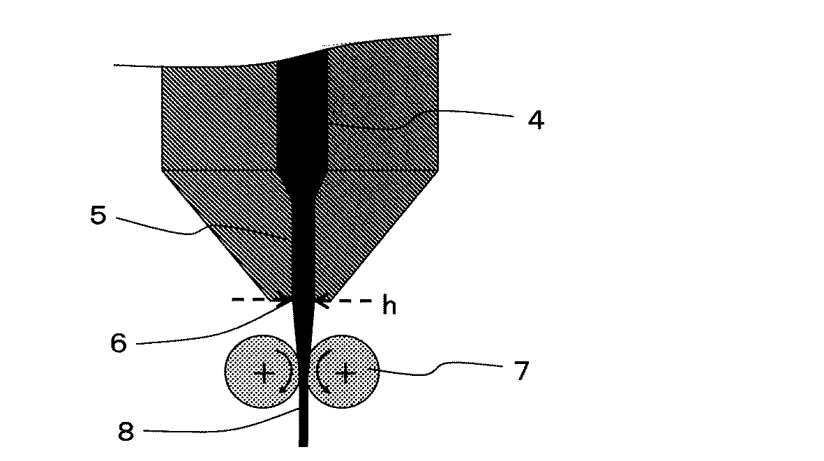
(考察)
表1の結果から、実施例1〜9の多層フィルムは、第1の熱可塑性樹脂層と、第2の熱可塑性樹脂層とが交互に積層されてなり、第2の熱可塑性樹脂層は、炭素フィラーを含有し、第1の熱可塑性樹脂層及び第2の熱可塑性樹脂層の積層数の合計が10以上であり、炭素フィラーが多層フィルムの面方向に対して略平行に配向しているので、引張弾性率、鉛筆硬度、及び引裂強力が高く、機械特性に優れていた。また、曇度が低く光学特性に優れていた。
(Discussion)
From the results of Table 1, the multilayer films of Examples 1 to 9 are formed by alternately laminating the first thermoplastic resin layer and the second thermoplastic resin layer, and the second thermoplastic resin layer is It contains a carbon filler, the total number of laminated layers of the first thermoplastic resin layer and the second thermoplastic resin layer is 10 or more, and the carbon filler is oriented substantially parallel to the plane direction of the multilayer film. Therefore, the tensile modulus, pencil hardness, and tear strength were high, and the mechanical properties were excellent. Further, the haze was low and the optical characteristics were excellent.
比較例1〜5の多層フィルムは、第2の熱可塑性樹脂層が炭素フィラーを含有していないため機械特性に劣り、引張弾性率、鉛筆硬度、及び引裂強力が低かった。 The multilayer films of Comparative Examples 1 to 5 were inferior in mechanical properties because the second thermoplastic resin layer did not contain a carbon filler, and had low tensile elastic modulus, pencil hardness, and tear strength.
比較例6の多層フィルムは、炭素フィラーを用いず、炭酸カルシウムを主成分とする針状無機フィラーを用いているため、機械特性に劣り、引張弾性率、鉛筆硬度、及び引裂強力が低かった。また、曇度が高く光学特性に劣っていた。 Since the multilayer film of Comparative Example 6 did not use a carbon filler and used a needle-like inorganic filler mainly composed of calcium carbonate, it was inferior in mechanical properties and had low tensile elastic modulus, pencil hardness, and tear strength. Further, the haze was high and the optical properties were poor.
比較例7の多層フィルムは、積層数の合計が少ないため、機械特性に劣り、引張弾性率、鉛筆硬度、及び引裂強力が低かった。また、曇度が高く光学特性に劣っていた。 Since the multilayer film of Comparative Example 7 had a small total number of laminated layers, it was inferior in mechanical properties and had low tensile elastic modulus, pencil hardness, and tear strength. Further, the haze was high and the optical properties were poor.
比較例8の多層フィルムは、ダイリップ開口部のクリアランスが広く、炭素フィラーが多層フィルムの面方向に対して略平行に配向できなかったため、機械特性に劣り、引張弾性率、鉛筆硬度、及び引裂強力が低かった。また、曇度が高く光学特性に劣っていた。 The multilayer film of Comparative Example 8 has a wide clearance of the die lip opening, and the carbon filler cannot be oriented substantially parallel to the plane direction of the multilayer film. Therefore, the mechanical properties are inferior, and the tensile elastic modulus, pencil hardness, and tear strength are low. Was low. Further, the haze was high and the optical properties were poor.
1…多層フィルム
21,22,23,24,25,26…第1の熱可塑性樹脂層
31,32,33,34,35,36,37…第2の熱可塑性樹脂層
4…樹脂積層体
5…ランド
6…ダイリップ
7…冷却ロール
8…多層フィルム
h…ダイリップ開口部のクリアランス
DESCRIPTION OF
Claims (5)
前記第2の熱可塑性樹脂層は、炭素フィラーを含有し、
前記第1の熱可塑性樹脂層、及び、前記第2の熱可塑性樹脂層の積層数の合計が、10以上であり、
前記炭素フィラーは、多層フィルムの面方向に対して略平行に配向している
ことを特徴とする多層フィルム。 A multilayer film in which a first thermoplastic resin layer and a second thermoplastic resin layer are alternately laminated,
The second thermoplastic resin layer contains a carbon filler,
The total number of laminations of the first thermoplastic resin layer and the second thermoplastic resin layer is 10 or more;
The carbon filler is oriented substantially parallel to the plane direction of the multilayer film.
熱可塑性樹脂組成物及び炭素フィラー含有熱可塑性樹脂組成物を、溶融押出法によりダイリップ開口部から吐出して、熱可塑性樹脂組成物からなる第1の熱可塑性樹脂層と、炭素フィラー含有熱可塑性樹脂組成物からなる第2の熱可塑性樹脂層とが交互に積層された多層フィルムを得る工程1を有し、
前記第1の熱可塑性樹脂層、及び前記第2の熱可塑性樹脂層の積層数の合計が、10以上であり、
前記ダイリップ開口部のクリアランスは、0.5mm以下であり、
前記炭素フィラーは、多層フィルムの面方向に対して略平行に配向している、
ことを特徴とする多層フィルムの製造方法。 It is a manufacturing method of the multilayer film in any one of Claims 1-3,
A thermoplastic resin composition and a carbon filler-containing thermoplastic resin composition are ejected from a die lip opening by a melt extrusion method, and a first thermoplastic resin layer comprising the thermoplastic resin composition, and a carbon filler-containing thermoplastic resin Having a step 1 of obtaining a multilayer film in which second thermoplastic resin layers made of the composition are alternately laminated;
The total number of laminated layers of the first thermoplastic resin layer and the second thermoplastic resin layer is 10 or more;
The clearance of the die lip opening is 0.5 mm or less,
The carbon filler is oriented substantially parallel to the plane direction of the multilayer film,
A method for producing a multilayer film.
Priority Applications (1)
| Application Number | Priority Date | Filing Date | Title |
|---|---|---|---|
| JP2012074064A JP2013202920A (en) | 2012-03-28 | 2012-03-28 | Multilayer film and method of manufacturing the same |
Applications Claiming Priority (1)
| Application Number | Priority Date | Filing Date | Title |
|---|---|---|---|
| JP2012074064A JP2013202920A (en) | 2012-03-28 | 2012-03-28 | Multilayer film and method of manufacturing the same |
Publications (1)
| Publication Number | Publication Date |
|---|---|
| JP2013202920A true JP2013202920A (en) | 2013-10-07 |
Family
ID=49522554
Family Applications (1)
| Application Number | Title | Priority Date | Filing Date |
|---|---|---|---|
| JP2012074064A Pending JP2013202920A (en) | 2012-03-28 | 2012-03-28 | Multilayer film and method of manufacturing the same |
Country Status (1)
| Country | Link |
|---|---|
| JP (1) | JP2013202920A (en) |
Cited By (1)
| Publication number | Priority date | Publication date | Assignee | Title |
|---|---|---|---|---|
| JP2014065199A (en) * | 2012-09-25 | 2014-04-17 | Sumitomo Bakelite Co Ltd | Multilayer film and package |
Citations (5)
| Publication number | Priority date | Publication date | Assignee | Title |
|---|---|---|---|---|
| JP2002273741A (en) * | 2001-03-15 | 2002-09-25 | Polymatech Co Ltd | Carbon nano-tube composite molded object and method for manufacturing the same |
| JP2004148634A (en) * | 2002-10-30 | 2004-05-27 | Toppan Printing Co Ltd | Laminate having antistatic function |
| JP2004292656A (en) * | 2003-03-27 | 2004-10-21 | Teijin Dupont Films Japan Ltd | Biaxially orientated thermoplastic resin film and laminated biaxially orientated thermoplastic resin film, and magnetic recording medium |
| WO2009041170A1 (en) * | 2007-09-28 | 2009-04-02 | Toray Industries, Inc. | Conductive film and method for producing the same |
| JP2011213090A (en) * | 2009-09-29 | 2011-10-27 | Sekisui Chem Co Ltd | Resin laminated sheet |
-
2012
- 2012-03-28 JP JP2012074064A patent/JP2013202920A/en active Pending
Patent Citations (5)
| Publication number | Priority date | Publication date | Assignee | Title |
|---|---|---|---|---|
| JP2002273741A (en) * | 2001-03-15 | 2002-09-25 | Polymatech Co Ltd | Carbon nano-tube composite molded object and method for manufacturing the same |
| JP2004148634A (en) * | 2002-10-30 | 2004-05-27 | Toppan Printing Co Ltd | Laminate having antistatic function |
| JP2004292656A (en) * | 2003-03-27 | 2004-10-21 | Teijin Dupont Films Japan Ltd | Biaxially orientated thermoplastic resin film and laminated biaxially orientated thermoplastic resin film, and magnetic recording medium |
| WO2009041170A1 (en) * | 2007-09-28 | 2009-04-02 | Toray Industries, Inc. | Conductive film and method for producing the same |
| JP2011213090A (en) * | 2009-09-29 | 2011-10-27 | Sekisui Chem Co Ltd | Resin laminated sheet |
Cited By (1)
| Publication number | Priority date | Publication date | Assignee | Title |
|---|---|---|---|---|
| JP2014065199A (en) * | 2012-09-25 | 2014-04-17 | Sumitomo Bakelite Co Ltd | Multilayer film and package |
Similar Documents
| Publication | Publication Date | Title |
|---|---|---|
| JP6508043B2 (en) | Biaxially oriented polypropylene film | |
| JP6527505B2 (en) | Method of manufacturing biaxially stretched film | |
| TWI589436B (en) | Retardation film laminate, manufacturing method of retardation film laminate and method of manufacturing retardation film | |
| JP6828437B2 (en) | Adhesive film and adhesive film roll | |
| JP2013103368A (en) | Multi-layer film | |
| JP7443553B2 (en) | Liquid crystal polymer film, flexible copper clad laminate, and method for producing liquid crystal polymer film | |
| JP2007003975A (en) | Polypropylene film for light reflection board | |
| JP2008276163A (en) | Optical film | |
| JP2012173487A (en) | Optical film and method for manufacturing optical film | |
| TW201834861A (en) | Biaxially oriented polypropylene-based film | |
| JP2013202919A (en) | Multilayer film | |
| JP5898925B2 (en) | Multilayer film | |
| JP2004269766A (en) | Biaxially oriented polyester film | |
| JP2010243820A (en) | Method of manufacturing retardation compensation film, retardation compensation film, composite polarizing plate, polarizing plate, and liquid crystal display device | |
| JP5637924B2 (en) | Method for producing retardation film | |
| JP2013195939A (en) | Method of manufacturing retardation film | |
| JP2005105255A (en) | Biaxially oriented polyester film | |
| JP2018044102A (en) | Manufacturing method of film | |
| JP2013202920A (en) | Multilayer film and method of manufacturing the same | |
| JP2012173486A (en) | Optical film and method for manufacturing optical film | |
| JP2010243818A (en) | Method of manufacturing retardation compensation film, retardation compensation film, composite polarizing plate, polarizing plate, and liquid crystal display device | |
| JP2010243819A (en) | Method of manufacturing retardation compensation film, retardation compensation film, composite polarizing plate, polarizing plate, and liquid crystal display device | |
| JP6809621B2 (en) | Manufacturing method of thermoplastic resin stretched sheet | |
| JP6753540B1 (en) | Polyolefin film and mold release film | |
| JP6743475B2 (en) | Peelable laminated stretched sheet |
Legal Events
| Date | Code | Title | Description |
|---|---|---|---|
| A621 | Written request for application examination |
Free format text: JAPANESE INTERMEDIATE CODE: A621 Effective date: 20141202 |
|
| A977 | Report on retrieval |
Free format text: JAPANESE INTERMEDIATE CODE: A971007 Effective date: 20150831 |
|
| A131 | Notification of reasons for refusal |
Free format text: JAPANESE INTERMEDIATE CODE: A131 Effective date: 20150915 |
|
| A02 | Decision of refusal |
Free format text: JAPANESE INTERMEDIATE CODE: A02 Effective date: 20160126 |