JP2013149741A - Photoelectric conversion device, imaging system, and method for manufacturing photoelectric conversion device - Google Patents
Photoelectric conversion device, imaging system, and method for manufacturing photoelectric conversion device Download PDFInfo
- Publication number
- JP2013149741A JP2013149741A JP2012008200A JP2012008200A JP2013149741A JP 2013149741 A JP2013149741 A JP 2013149741A JP 2012008200 A JP2012008200 A JP 2012008200A JP 2012008200 A JP2012008200 A JP 2012008200A JP 2013149741 A JP2013149741 A JP 2013149741A
- Authority
- JP
- Japan
- Prior art keywords
- photoelectric conversion
- silicon oxide
- nitrogen concentration
- oxide film
- atomic
- Prior art date
- Legal status (The legal status is an assumption and is not a legal conclusion. Google has not performed a legal analysis and makes no representation as to the accuracy of the status listed.)
- Granted
Links
- 238000006243 chemical reaction Methods 0.000 title claims abstract description 226
- 238000000034 method Methods 0.000 title claims description 68
- 238000004519 manufacturing process Methods 0.000 title claims description 19
- 238000003384 imaging method Methods 0.000 title claims description 11
- IJGRMHOSHXDMSA-UHFFFAOYSA-N Atomic nitrogen Chemical compound N#N IJGRMHOSHXDMSA-UHFFFAOYSA-N 0.000 claims abstract description 437
- 229910052757 nitrogen Inorganic materials 0.000 claims abstract description 219
- VYPSYNLAJGMNEJ-UHFFFAOYSA-N Silicium dioxide Chemical group O=[Si]=O VYPSYNLAJGMNEJ-UHFFFAOYSA-N 0.000 claims abstract description 146
- 229910052814 silicon oxide Inorganic materials 0.000 claims abstract description 146
- 239000004065 semiconductor Substances 0.000 claims abstract description 49
- 239000004020 conductor Substances 0.000 claims abstract description 18
- 239000012212 insulator Substances 0.000 claims abstract description 13
- XUIMIQQOPSSXEZ-UHFFFAOYSA-N Silicon Chemical compound [Si] XUIMIQQOPSSXEZ-UHFFFAOYSA-N 0.000 claims description 58
- 229910052710 silicon Inorganic materials 0.000 claims description 58
- 239000010703 silicon Substances 0.000 claims description 58
- 239000012535 impurity Substances 0.000 claims description 34
- 230000003647 oxidation Effects 0.000 claims description 26
- 238000007254 oxidation reaction Methods 0.000 claims description 26
- 230000008569 process Effects 0.000 claims description 25
- 238000005121 nitriding Methods 0.000 claims description 24
- 230000003321 amplification Effects 0.000 claims description 23
- 238000003199 nucleic acid amplification method Methods 0.000 claims description 23
- 229910021420 polycrystalline silicon Inorganic materials 0.000 claims description 23
- 229920005591 polysilicon Polymers 0.000 claims description 23
- 229910021332 silicide Inorganic materials 0.000 claims description 16
- FVBUAEGBCNSCDD-UHFFFAOYSA-N silicide(4-) Chemical compound [Si-4] FVBUAEGBCNSCDD-UHFFFAOYSA-N 0.000 claims description 16
- 238000000059 patterning Methods 0.000 claims description 14
- 238000005468 ion implantation Methods 0.000 claims description 10
- 238000005530 etching Methods 0.000 claims description 7
- 238000000137 annealing Methods 0.000 claims description 4
- 230000015572 biosynthetic process Effects 0.000 claims description 2
- 239000000758 substrate Substances 0.000 claims description 2
- 230000002093 peripheral effect Effects 0.000 description 152
- 239000010410 layer Substances 0.000 description 86
- 238000009826 distribution Methods 0.000 description 29
- 229910052581 Si3N4 Inorganic materials 0.000 description 24
- HQVNEWCFYHHQES-UHFFFAOYSA-N silicon nitride Chemical compound N12[Si]34N5[Si]62N3[Si]51N64 HQVNEWCFYHHQES-UHFFFAOYSA-N 0.000 description 24
- 230000006870 function Effects 0.000 description 19
- 229910052751 metal Inorganic materials 0.000 description 15
- 239000002184 metal Substances 0.000 description 15
- 238000010586 diagram Methods 0.000 description 11
- ZOXJGFHDIHLPTG-UHFFFAOYSA-N Boron Chemical compound [B] ZOXJGFHDIHLPTG-UHFFFAOYSA-N 0.000 description 9
- 229910052796 boron Inorganic materials 0.000 description 9
- 125000006850 spacer group Chemical group 0.000 description 9
- 230000003287 optical effect Effects 0.000 description 8
- 229920002120 photoresistant polymer Polymers 0.000 description 8
- 238000000926 separation method Methods 0.000 description 7
- KRHYYFGTRYWZRS-UHFFFAOYSA-N Fluorane Chemical compound F KRHYYFGTRYWZRS-UHFFFAOYSA-N 0.000 description 6
- 238000001312 dry etching Methods 0.000 description 6
- OAICVXFJPJFONN-UHFFFAOYSA-N Phosphorus Chemical compound [P] OAICVXFJPJFONN-UHFFFAOYSA-N 0.000 description 5
- 125000004429 atom Chemical group 0.000 description 5
- 238000009792 diffusion process Methods 0.000 description 5
- 230000015654 memory Effects 0.000 description 5
- 229910052698 phosphorus Inorganic materials 0.000 description 5
- 239000011574 phosphorus Substances 0.000 description 5
- 238000004833 X-ray photoelectron spectroscopy Methods 0.000 description 4
- 229910052785 arsenic Inorganic materials 0.000 description 4
- RQNWIZPPADIBDY-UHFFFAOYSA-N arsenic atom Chemical compound [As] RQNWIZPPADIBDY-UHFFFAOYSA-N 0.000 description 4
- 239000007789 gas Substances 0.000 description 4
- 239000011229 interlayer Substances 0.000 description 4
- 238000002955 isolation Methods 0.000 description 4
- 239000000463 material Substances 0.000 description 4
- 238000001004 secondary ion mass spectrometry Methods 0.000 description 4
- RYGMFSIKBFXOCR-UHFFFAOYSA-N Copper Chemical compound [Cu] RYGMFSIKBFXOCR-UHFFFAOYSA-N 0.000 description 3
- 238000009825 accumulation Methods 0.000 description 3
- 238000005229 chemical vapour deposition Methods 0.000 description 3
- 229910052802 copper Inorganic materials 0.000 description 3
- 239000010949 copper Substances 0.000 description 3
- 230000007423 decrease Effects 0.000 description 3
- 238000001514 detection method Methods 0.000 description 3
- 239000011810 insulating material Substances 0.000 description 3
- 238000009413 insulation Methods 0.000 description 3
- 229910017855 NH 4 F Inorganic materials 0.000 description 2
- 229910052782 aluminium Inorganic materials 0.000 description 2
- XAGFODPZIPBFFR-UHFFFAOYSA-N aluminium Chemical compound [Al] XAGFODPZIPBFFR-UHFFFAOYSA-N 0.000 description 2
- 230000000295 complement effect Effects 0.000 description 2
- 238000011049 filling Methods 0.000 description 2
- 125000005843 halogen group Chemical group 0.000 description 2
- 238000001095 inductively coupled plasma mass spectrometry Methods 0.000 description 2
- QPJSUIGXIBEQAC-UHFFFAOYSA-N n-(2,4-dichloro-5-propan-2-yloxyphenyl)acetamide Chemical compound CC(C)OC1=CC(NC(C)=O)=C(Cl)C=C1Cl QPJSUIGXIBEQAC-UHFFFAOYSA-N 0.000 description 2
- 238000005375 photometry Methods 0.000 description 2
- 230000009467 reduction Effects 0.000 description 2
- 238000005001 rutherford backscattering spectroscopy Methods 0.000 description 2
- 230000035945 sensitivity Effects 0.000 description 2
- HBMJWWWQQXIZIP-UHFFFAOYSA-N silicon carbide Chemical compound [Si+]#[C-] HBMJWWWQQXIZIP-UHFFFAOYSA-N 0.000 description 2
- 229910010271 silicon carbide Inorganic materials 0.000 description 2
- 238000004544 sputter deposition Methods 0.000 description 2
- 238000003860 storage Methods 0.000 description 2
- DDFHBQSCUXNBSA-UHFFFAOYSA-N 5-(5-carboxythiophen-2-yl)thiophene-2-carboxylic acid Chemical compound S1C(C(=O)O)=CC=C1C1=CC=C(C(O)=O)S1 DDFHBQSCUXNBSA-UHFFFAOYSA-N 0.000 description 1
- RTAQQCXQSZGOHL-UHFFFAOYSA-N Titanium Chemical compound [Ti] RTAQQCXQSZGOHL-UHFFFAOYSA-N 0.000 description 1
- 238000004458 analytical method Methods 0.000 description 1
- QVGXLLKOCUKJST-UHFFFAOYSA-N atomic oxygen Chemical compound [O] QVGXLLKOCUKJST-UHFFFAOYSA-N 0.000 description 1
- 230000008901 benefit Effects 0.000 description 1
- 230000005540 biological transmission Effects 0.000 description 1
- 230000000740 bleeding effect Effects 0.000 description 1
- 239000005380 borophosphosilicate glass Substances 0.000 description 1
- 230000008859 change Effects 0.000 description 1
- 239000010941 cobalt Substances 0.000 description 1
- 229910017052 cobalt Inorganic materials 0.000 description 1
- GUTLYIVDDKVIGB-UHFFFAOYSA-N cobalt atom Chemical compound [Co] GUTLYIVDDKVIGB-UHFFFAOYSA-N 0.000 description 1
- 239000000470 constituent Substances 0.000 description 1
- 230000007547 defect Effects 0.000 description 1
- 239000006185 dispersion Substances 0.000 description 1
- 230000005669 field effect Effects 0.000 description 1
- 230000004927 fusion Effects 0.000 description 1
- 238000002513 implantation Methods 0.000 description 1
- 150000002500 ions Chemical class 0.000 description 1
- 239000011159 matrix material Substances 0.000 description 1
- 238000005259 measurement Methods 0.000 description 1
- 150000002829 nitrogen Chemical class 0.000 description 1
- 229910052760 oxygen Inorganic materials 0.000 description 1
- 239000001301 oxygen Substances 0.000 description 1
- 238000002161 passivation Methods 0.000 description 1
- 238000005036 potential barrier Methods 0.000 description 1
- 230000001105 regulatory effect Effects 0.000 description 1
- 238000004904 shortening Methods 0.000 description 1
- 239000005368 silicate glass Substances 0.000 description 1
- 230000003595 spectral effect Effects 0.000 description 1
- 238000004347 surface barrier Methods 0.000 description 1
- -1 that is Chemical compound 0.000 description 1
- 239000010936 titanium Substances 0.000 description 1
- 229910052719 titanium Inorganic materials 0.000 description 1
- WFKWXMTUELFFGS-UHFFFAOYSA-N tungsten Chemical compound [W] WFKWXMTUELFFGS-UHFFFAOYSA-N 0.000 description 1
- 229910052721 tungsten Inorganic materials 0.000 description 1
- 239000010937 tungsten Substances 0.000 description 1
- 238000001039 wet etching Methods 0.000 description 1
Images


Classifications
-
- H—ELECTRICITY
- H01—ELECTRIC ELEMENTS
- H01L—SEMICONDUCTOR DEVICES NOT COVERED BY CLASS H10
- H01L27/00—Devices consisting of a plurality of semiconductor or other solid-state components formed in or on a common substrate
- H01L27/14—Devices consisting of a plurality of semiconductor or other solid-state components formed in or on a common substrate including semiconductor components sensitive to infrared radiation, light, electromagnetic radiation of shorter wavelength or corpuscular radiation and specially adapted either for the conversion of the energy of such radiation into electrical energy or for the control of electrical energy by such radiation
- H01L27/144—Devices controlled by radiation
- H01L27/146—Imager structures
- H01L27/14601—Structural or functional details thereof
- H01L27/14609—Pixel-elements with integrated switching, control, storage or amplification elements
- H01L27/14612—Pixel-elements with integrated switching, control, storage or amplification elements involving a transistor
- H01L27/14614—Pixel-elements with integrated switching, control, storage or amplification elements involving a transistor having a special gate structure
-
- H—ELECTRICITY
- H01—ELECTRIC ELEMENTS
- H01L—SEMICONDUCTOR DEVICES NOT COVERED BY CLASS H10
- H01L27/00—Devices consisting of a plurality of semiconductor or other solid-state components formed in or on a common substrate
- H01L27/14—Devices consisting of a plurality of semiconductor or other solid-state components formed in or on a common substrate including semiconductor components sensitive to infrared radiation, light, electromagnetic radiation of shorter wavelength or corpuscular radiation and specially adapted either for the conversion of the energy of such radiation into electrical energy or for the control of electrical energy by such radiation
- H01L27/144—Devices controlled by radiation
- H01L27/146—Imager structures
- H01L27/14601—Structural or functional details thereof
- H01L27/14609—Pixel-elements with integrated switching, control, storage or amplification elements
- H01L27/14612—Pixel-elements with integrated switching, control, storage or amplification elements involving a transistor
-
- H—ELECTRICITY
- H01—ELECTRIC ELEMENTS
- H01L—SEMICONDUCTOR DEVICES NOT COVERED BY CLASS H10
- H01L27/00—Devices consisting of a plurality of semiconductor or other solid-state components formed in or on a common substrate
- H01L27/14—Devices consisting of a plurality of semiconductor or other solid-state components formed in or on a common substrate including semiconductor components sensitive to infrared radiation, light, electromagnetic radiation of shorter wavelength or corpuscular radiation and specially adapted either for the conversion of the energy of such radiation into electrical energy or for the control of electrical energy by such radiation
- H01L27/144—Devices controlled by radiation
- H01L27/146—Imager structures
- H01L27/14683—Processes or apparatus peculiar to the manufacture or treatment of these devices or parts thereof
- H01L27/14689—MOS based technologies
-
- H—ELECTRICITY
- H01—ELECTRIC ELEMENTS
- H01L—SEMICONDUCTOR DEVICES NOT COVERED BY CLASS H10
- H01L27/00—Devices consisting of a plurality of semiconductor or other solid-state components formed in or on a common substrate
- H01L27/14—Devices consisting of a plurality of semiconductor or other solid-state components formed in or on a common substrate including semiconductor components sensitive to infrared radiation, light, electromagnetic radiation of shorter wavelength or corpuscular radiation and specially adapted either for the conversion of the energy of such radiation into electrical energy or for the control of electrical energy by such radiation
- H01L27/144—Devices controlled by radiation
- H01L27/146—Imager structures
- H01L27/14683—Processes or apparatus peculiar to the manufacture or treatment of these devices or parts thereof
- H01L27/14698—Post-treatment for the devices, e.g. annealing, impurity-gettering, shor-circuit elimination, recrystallisation
-
- H—ELECTRICITY
- H01—ELECTRIC ELEMENTS
- H01L—SEMICONDUCTOR DEVICES NOT COVERED BY CLASS H10
- H01L31/00—Semiconductor devices sensitive to infrared radiation, light, electromagnetic radiation of shorter wavelength or corpuscular radiation and specially adapted either for the conversion of the energy of such radiation into electrical energy or for the control of electrical energy by such radiation; Processes or apparatus specially adapted for the manufacture or treatment thereof or of parts thereof; Details thereof
- H01L31/18—Processes or apparatus specially adapted for the manufacture or treatment of these devices or of parts thereof
- H01L31/186—Particular post-treatment for the devices, e.g. annealing, impurity gettering, short-circuit elimination, recrystallisation
- H01L31/1864—Annealing
-
- H—ELECTRICITY
- H01—ELECTRIC ELEMENTS
- H01L—SEMICONDUCTOR DEVICES NOT COVERED BY CLASS H10
- H01L29/00—Semiconductor devices adapted for rectifying, amplifying, oscillating or switching, or capacitors or resistors with at least one potential-jump barrier or surface barrier, e.g. PN junction depletion layer or carrier concentration layer; Details of semiconductor bodies or of electrodes thereof ; Multistep manufacturing processes therefor
- H01L29/40—Electrodes ; Multistep manufacturing processes therefor
- H01L29/43—Electrodes ; Multistep manufacturing processes therefor characterised by the materials of which they are formed
- H01L29/49—Metal-insulator-semiconductor electrodes, e.g. gates of MOSFET
- H01L29/51—Insulating materials associated therewith
- H01L29/518—Insulating materials associated therewith the insulating material containing nitrogen, e.g. nitride, oxynitride, nitrogen-doped material
-
- Y—GENERAL TAGGING OF NEW TECHNOLOGICAL DEVELOPMENTS; GENERAL TAGGING OF CROSS-SECTIONAL TECHNOLOGIES SPANNING OVER SEVERAL SECTIONS OF THE IPC; TECHNICAL SUBJECTS COVERED BY FORMER USPC CROSS-REFERENCE ART COLLECTIONS [XRACs] AND DIGESTS
- Y02—TECHNOLOGIES OR APPLICATIONS FOR MITIGATION OR ADAPTATION AGAINST CLIMATE CHANGE
- Y02E—REDUCTION OF GREENHOUSE GAS [GHG] EMISSIONS, RELATED TO ENERGY GENERATION, TRANSMISSION OR DISTRIBUTION
- Y02E10/00—Energy generation through renewable energy sources
- Y02E10/50—Photovoltaic [PV] energy
Landscapes
- Engineering & Computer Science (AREA)
- Power Engineering (AREA)
- Physics & Mathematics (AREA)
- Computer Hardware Design (AREA)
- General Physics & Mathematics (AREA)
- Condensed Matter Physics & Semiconductors (AREA)
- Electromagnetism (AREA)
- Microelectronics & Electronic Packaging (AREA)
- Manufacturing & Machinery (AREA)
- Solid State Image Pick-Up Elements (AREA)
- Light Receiving Elements (AREA)
- Transforming Light Signals Into Electric Signals (AREA)
- Metal-Oxide And Bipolar Metal-Oxide Semiconductor Integrated Circuits (AREA)
Abstract
Description
本発明は光電変換装置の導電体−絶縁体−半導体の積層構造における絶縁体に関する。 The present invention relates to an insulator in a stacked structure of a conductor-insulator-semiconductor of a photoelectric conversion device.
CMOSイメージセンサを始めとした光電変換装置には、光電変換手段と、光電変換手段からの信号を処理する信号処理手段が設けられる。光電変換手段は、各々がMOSFETを含む複数の光電変換ユニットで構成することできる。 Photoelectric conversion devices such as CMOS image sensors are provided with photoelectric conversion means and signal processing means for processing signals from the photoelectric conversion means. The photoelectric conversion means can be composed of a plurality of photoelectric conversion units each including a MOSFET.
特許文献1、2には、光電変換ユニットのMOSFETに、窒化されたゲート絶縁膜を用いることが記載されている。窒化されたゲート絶縁膜を用いることで、一般的な熱酸化法を用いて形成された酸化シリコンからなるゲート絶縁膜よりも誘電率を大きくでき、リーク電流を低減しつつ、光電変換手段を良好に動作させることができる。
しかし、特許文献1、2のように窒化されたゲート絶縁膜を用いた場合、光電変換手段に十分な性能が得られない場合があった。そこで、本発明は、光電変換手段の性能を向上することを目的とする。
However, when a nitrided gate insulating film is used as in
上記課題を解決するための第1の観点は、光電変換手段を備えた光電変換装置において、前記光電変換手段は、導電体、半導体、および前記導電体と前記半導体との間に設けられた絶縁体からなる積層構造を有する半導体素子を含み、前記絶縁体は、前記導電体と前記半導体との間に位置する主部において窒素を含有する酸化シリコン膜であって、前記主部の最高窒素濃度が0.10原子%より高く、前記主部の前記半導体側の面における界面窒素濃度が0.10原子%以下であることを特徴とする。 According to a first aspect of the present invention, there is provided a photoelectric conversion apparatus including a photoelectric conversion unit, wherein the photoelectric conversion unit includes a conductor, a semiconductor, and an insulation provided between the conductor and the semiconductor. A semiconductor element having a laminated structure composed of a body, wherein the insulator is a silicon oxide film containing nitrogen in a main portion located between the conductor and the semiconductor, and the highest nitrogen concentration in the main portion Is higher than 0.10 atomic%, and the interface nitrogen concentration in the semiconductor-side surface of the main part is 0.10 atomic% or less.
また、上記課題を解決するための第2の観点は、第1領域に、MOSFETを有する光電変換手段と、第2領域に、nMOSFETおよびpMOSFETを有する信号処理手段と、を備えた光電変換装置の製造方法において、シリコンウエハの第1領域に第1酸化シリコン膜を形成し、前記シリコンウエハの第2領域の或る部分に第2酸化シリコン膜を形成する酸化シリコン膜形成工程と、プラズマ窒化法を用いて、前記第1酸化シリコン膜と前記第2酸化シリコン膜へ窒素を同時に導入する窒化工程と、窒素が導入された前記第1酸化シリコン膜の上に、前記MOSFETのゲート電極をパターニングし、窒素が導入された前記第2酸化シリコン膜の上に、前記nMOSFETおよび前記pMOSFETのゲート電極をパターニングするパターニング工程と、を有し、前記窒化工程を、前記第1酸化シリコン膜の最高窒素濃度が0.50原子%以上となり、前記第1酸化シリコン膜の前記シリコンウエハ側の面における界面窒素濃度が0.10原子%以下となるように行うことを特徴とする。 A second aspect for solving the above-described problem is a photoelectric conversion device including a photoelectric conversion unit having a MOSFET in a first region and a signal processing unit having an nMOSFET and a pMOSFET in a second region. In the manufacturing method, a silicon oxide film forming step of forming a first silicon oxide film in a first region of the silicon wafer and forming a second silicon oxide film in a certain part of the second region of the silicon wafer, and a plasma nitriding method Nitriding step of simultaneously introducing nitrogen into the first silicon oxide film and the second silicon oxide film, and patterning a gate electrode of the MOSFET on the first silicon oxide film into which nitrogen has been introduced. A gate electrode for patterning the nMOSFET and the pMOSFET on the second silicon oxide film introduced with nitrogen; A nitriding step, wherein the maximum nitrogen concentration of the first silicon oxide film is 0.50 atomic% or more, and the interface nitrogen concentration on the surface of the first silicon oxide film on the silicon wafer side is It is performed so that it may become 0.10 atomic% or less.
本発明によれば、光電変換手段の性能が向上した光電変換装置を提供することができる。 ADVANTAGE OF THE INVENTION According to this invention, the photoelectric conversion apparatus which the performance of the photoelectric conversion means improved can be provided.
以下、本発明の実施形態を、図面を用いて説明する。なお、各図は相互に参照することができ、共通の機能あるいは構造を示す部材については同じ符号を用いて説明する。 Hereinafter, embodiments of the present invention will be described with reference to the drawings. In addition, each figure can mutually be referred and the member which shows a common function or structure is demonstrated using the same code | symbol.
図1を用いて光電変換装置1の一例を説明する。光電変換装置1には光電変換手段10が設けられている。本実施形態の光電変換装置には、信号処理手段20と駆動手段30がさらに設けられている。本例の光電変換手段10は、2次元状に配列された複数の光電変換ユニット11で構成されているが、複数の光電変換ユニット11を1次元状に配列してもよい。光電変換ユニット11は光電変換部を含む。光電変換手段10は光電変換ユニット11にマトリックス接続された垂直出力線12と水平走査線13を含んでいる。垂直出力線12は信号処理手段20に接続されており、水平走査線13は駆動手段30に接続されている。本例の垂直出力線12および水平走査線13は銅またはアルミニウムを主成分とする金属配線であり、配線を低抵抗とする上では銅を主成分とする金属配線を用いることが好ましい。光電変換手段10が配された領域を光電変換領域(第1領域)と呼び、信号処理手段20と駆動手段30が配された領域を併せて周辺領域(第2領域)と呼ぶ。信号処理手段20と駆動手段30の構成は後で説明する。
An example of the
図2は光電変換ユニット11の回路構成の一例を示している。本例の光電変換ユニット11は、実質的に等価な回路を2つ組み合わせた構成になっている。以下、図2における左半分の回路を主に説明し、同じ光電変換ユニット11の左半分の回路に対応する右半分の回路については括弧を付けて補足的に説明する。図3(a)は図2の回路構成を有する光電変換ユニット11を2行×2列に4つ配列した際のレイアウトを示す平面模式図である。このレイアウトは、1行目と2行目で並進対称であり、1列目と2列目で線対称となっている。図面の制約上、各光電変換ユニット11の一部の構成部材は1行目1列目の光電変換ユニット11を、残りの一部の構成部材は2行目1列目の光電変換ユニット11を用いて説明している。
FIG. 2 shows an example of the circuit configuration of the
光電変換ユニット11は2つの光電変換部101(102)を含んでいる。本例では光電変換部101、102はフォトダイオードである。転送トランジスタ103(104)は、光電変換部101(102)をソースとする。転送トランジスタ103(104)のゲート電極1340は、転送トランジスタ103と転送トランジスタ104とで一体となっているが、別体として設けてもよい。転送トランジスタ103(104)のゲート電極1340には第1の水平走査線が接続される。転送トランジスタ103(104)のドレイン1032(1042)はフローティングノード105(106)を介して、増幅トランジスタ107(108)のゲート電極1070(1080)に電気的に接続されている。転送トランジスタ103(104)のドレイン1032(1042)はフローティングディフージョンとして、フローティングノード105(106)の一部を成している。フローティングノード105(106)はドレイン1032(1042)以外に、ゲート電極1070(1080)とドレイン1032(1042)とを接続する配線を含み得る。フローティングノード105(106)には、光電変換部101(102)で発生した信号電荷の量に応じた電位が現れる。増幅トランジスタ107(108)はこのフローティングノード105(106)の電位に基づき、光電変換部101(102)で発生した信号電荷の量に応じた電気信号を生成する。
The
フローティングノード105(106)はリセットトランジスタ109(110)のソースに接続されている。リセットトランジスタ109(110)のゲート電極1090(1100)には第2の水平走査線が接続されている。増幅トランジスタ107(108)のドレイン1782およびリセットトランジスタ109(110)のドレイン1092(1102)は電源線を介して電源電位VDDに規定される。リセットトランジスタ109(110)は光電変換部101(102)で発生した信号電荷を、フローティングノード105(106)を介してリセットする。また、リセットトランジスタ109(110)はフローティングノード105(106)を介して、増幅トランジスタ107(108)のゲートを電源電位VDDにリセットする。
The floating node 105 (106) is connected to the source of the reset transistor 109 (110). A second horizontal scanning line is connected to the gate electrode 1090 (1100) of the reset transistor 109 (110). The
増幅トランジスタ107と増幅トランジスタ108は、それらのドレイン1782を共有している。転送トランジスタ103(104)のドレイン1032(1042)はリセットトランジスタ109のソースを兼ねている。
The
増幅トランジスタ107(108)のソース1071(1081)は、スイッチトランジスタ111(112)を介して垂直出力線113(114)に接続されている。増幅トランジスタ107(108)のソース1071(1081)はスイッチトランジスタ111(112)のドレインを兼ねている。スイッチトランジスタ111(112)のゲート電極1110(1120)には第3の水平走査線が接続され、スイッチトランジスタ111(112)のソース1112(1122)には垂直出力線113(114)が接続される。スイッチトランジスタ111(112)は光電変換ユニット11から垂直出力線12への出力のONまたはOFFの制御を行う。スイッチトランジスタ111(112)により、複数の光電変換ユニット11から信号を得る光電変換ユニット11を選択する。なお、スイッチトランジスタ111(112)を省略することもできる。また、転送トランジスタ103(104)を省略して、光電変換部101(102)と増幅トランジスタ107(108)のゲート電極1070(1080)とを、転送トランジスタを介さずに電気的に接続することもできる。
The source 1071 (1081) of the amplification transistor 107 (108) is connected to the vertical output line 113 (114) via the switch transistor 111 (112). The source 1071 (1081) of the amplification transistor 107 (108) also serves as the drain of the switch transistor 111 (112). A third horizontal scanning line is connected to the gate electrode 1110 (1120) of the switch transistor 111 (112), and a vertical output line 113 (114) is connected to the source 1112 (1122) of the switch transistor 111 (112). . The switch transistor 111 (112) controls ON / OFF of the output from the
このレイアウトでは、光電変換ユニット11間あるいは光電変換ユニット11内の素子分離に、絶縁分離部310および拡散分離部320を用いている。具体的には、2つの光電変換ユニット11の光電変換部同士および光電変換ユニット11内の2つの光電変換部101、102は、拡散分離部320で素子分離されている。光電変換ユニット11のトランジスタ同士は、図3(a)において、ハッチングを施していない部分は絶縁分離部310を示している。転送トランジスタ103(104)とリセットトランジスタ109(110)、および、増幅トランジスタ107(108)とスイッチトランジスタ111(112)を絶縁分離部310で素子分離して、金属配線を介して接続することもできる。
In this layout, the insulating
1つの光電変換ユニット11に対応する1つの光学ユニットを配することができる。光学ユニットはトップレンズと層内レンズの少なくとも一方のマイクロレンズを含み得る。図3(a)には、光学ユニットとして、トップレンズ120の輪郭を模式的に示している。また、1つの光学ユニットは1色のカラーフィルタを含み得る。複数色のカラーフィルタを光電変換ユニットごとに配列してマルチカラーフィルタを構成することができる。マルチカラーフィルタとしては典型的には赤色、緑色、青色の3色のカラーフィルタをベイヤー配列したものを用いることができる。本例では、2行目1列目の光電変換ユニット11には赤色のカラーフィルタが対応する。1行目1列目の光電変換ユニット11と2行目2列目の光電変換ユニット11には緑色のカラーフィルタが対応する。1行目2列目の光電変換ユニット11には青色のカラーフィルタが対応する。
One optical unit corresponding to one
図3(a)から理解されるように、本例の光電変換ユニット11は、1つの光学ユニットに対応した、2つの光電変換部101、102を有する。光電変換部を大面積化して感度を向上する場合、光電変換部を複数に分割して、複数の光電変換部101、102の各々から別々に信号電荷を転送することにより、転送効率の向上が可能となる。また、1つの光電変換ユニット11の複数の光電変換部101、102の信号電荷を別々に出力することで、焦点検出を可能にすることもできる。勿論、1つの光学ユニットに1つの光電変換部のみを対応させることもできる。
As understood from FIG. 3A, the
光電変換ユニット11を構成する転送トランジスタ103(104)、増幅トランジスタ107(108)、リセットトランジスタ109(110)およびスイッチトランジスタ111(112)は、いわゆるMOS構造を有する半導体素子である。そして、これらのトランジスタは、MOS構造を有するゲートに加えソースとドレインを有する、絶縁ゲート型電界効果トランジスタ(MOSFET:Metal−Oxide−Semiconductor Field−Effect−Transistor)である。なお、ここでいうMOS構造とは、導電体、半導体、および導電体と半導体との間に設けられた絶縁体からなる積層構造を意味する。本実施形態において、積層構造の導電体であるゲート電極は、金属電極であってもよいが、ポリシリコン電極であることが好ましい。そして、後述するように、MOSFETにおける積層構造の絶縁体であるゲート絶縁膜は純粋な酸化シリコン膜ではなく、窒素を含有する酸化シリコン膜である。以下、便宜的に、窒素を含有する酸化シリコン膜を酸窒化シリコン膜と称する場合がある。なお、窒素を含有する酸化シリコン膜の窒素はシリコンと結合している場合もあるし、結合していない場合もある。MOSFETにおける積層構造の半導体は、チャネルが形成されるチャネル領域である。
The transfer transistor 103 (104), the amplification transistor 107 (108), the reset transistor 109 (110), and the switch transistor 111 (112) constituting the
図4(a)は、光電変換ユニット11のトランジスタの断面模式図である。以下、光電変換ユニット11のMOSFETを「光電変換MOSFET」と称する。図4(a)に示した光電変換MOSFETの構造は、転送トランジスタ103(104)、増幅トランジスタ107(108)、リセットトランジスタ109(110)およびスイッチトランジスタ111(112)のいずれにも適用することができる。とりわけ、転送トランジスタ103(104)と増幅トランジスタ107(108)に適用することが好ましい。本例では、光電変換ユニット11の4つ×2のトランジスタの全てが、図4(a)に示した構造で説明される光電変換MOSFETである。
FIG. 4A is a schematic cross-sectional view of a transistor of the
本例の光電変換MOSFETは、ゲート絶縁膜として機能する酸化シリコン膜204を有している。詳細には、酸化シリコン膜204は、光電変換MOSFETのゲート電極130とチャネル領域2030との間に位置する主部2040を少なくとも有している。ゲート電極130と主部2040とチャネル領域2030を含むMOS構造が、光電変換MOSFETのゲートを成す。チャネル領域2030は半導体領域の一部であって、ここではウェル領域203として示している半導体領域の内、ソース201とドレイン202の間に位置する部分である。半導体領域がウェル領域であることに限定されるものではない。本例の酸化シリコン膜204は主部2040から、光電変換MOSFETのソース201およびドレイン202の上に延在した延在部2041を有している。延在部2041については後で説明する。
The photoelectric conversion MOSFET of this example includes a
主部2040のゲート電極130側の面を主部2040の上面と呼ぶ。主部2040の上面はゲート電極130の下面に接して、ゲート電極130と界面を成している。主部2040のチャネル領域2030側の面を主部2040の下面と呼ぶ。主部2040の下面はチャネル領域2030に接して、チャネル領域2030と界面を成している。なお、チャネル領域2030に形成されるチャネルは、主部2040の下面に接する場合もあるし、主部2040の下面から離れて形成される場合もある。後者は、チャネル領域2030を埋め込みチャネル構造とすることで実現可能である。
The surface of the
主部2040の厚みTは、主部2040の上面から下面までの距離であり、ゲート電極130からチャネル領域2030までの距離に等しい。主部2040の実用的な厚みTは1.0nm以上15nm以下である。主部2040の厚みTは5.0nm以上であることが好ましく、10nm以下であることも好ましい。本例の主部2040の厚みTは7.5nmである。
The thickness T of the
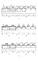
酸化シリコン膜204は、少なくとも主部2040において、窒素を含有する。本実施形態の酸化シリコン膜204に含有される窒素濃度は、主部2040の上面から下面にかけて均一ではなく、積層方向において分布を有する。この窒素濃度分布は、主部2040の最高窒素濃度が、主部2040の下面における窒素濃度すなわち界面窒素濃度よりも高い窒素濃度分布である。酸化シリコン膜204の窒素濃度分布は、X線光電子分光法(XPS)、二次イオン質量分析法(SIMS)、誘導結合プラズマ質量分析法(ICP−MS)、ラザフォード後方散乱分析法(RBS)などを用いて測定することが可能である。本例の窒素を含有する酸化シリコン膜204はプラズマ窒化法を用いて形成することができる。図5(a)の線Aに本例の光電変換MOSFETの主部2040における窒素濃度の分布を示す。図5(a)に示した窒素濃度分布は、SIMSで測定したものであり、SIMS装置としては、カメカインスツルメンツ社製のIMS−4F(型式)やULVAC−PHI社製のSIMS6650(型式)を用いることができる。なお、ReVera社製のRVX1000(型式)でXPS測定も行ったが、SIM測定による窒素濃度分布とXPS測定による窒素濃度分布はよい一致を示した。なお、参考例として図5(a)の線Bに光電変換MOSFETの主部2040を一般的な熱酸窒化法を用いて形成した場合における窒素濃度の分布を示す。熱酸窒化はN2Oガスを熱エネルギーにより分解し、酸素による酸化と、窒素による窒化が同時に起こるため、界面付近にピーク窒素濃度を有する濃度分布となる。ただし、熱酸化法を行った後に、ガス種を変えて熱酸窒化法を行うことによって類似の窒素濃度分布を得ることは可能である。本例の窒素濃度分布における最高窒素濃度は、明確なピーク(ピーク窒素濃度)を有している。そのため、以下の説明では、最高窒素濃度をピーク窒素濃度として説明する。ただし、主部2040は明確なピークがない窒素濃度分布を有していてもよく、例えば、最高窒素濃度となる領域が一定の幅をもって深さ方向に延在していてもよい。
The
主部2040における実用的なピーク窒素濃度Cpは、0.50原子%以上である。ピーク窒素濃度Cpは10.00原子%以下であることが好ましく、5.00原子%以下であることがより好ましい。本例では主部の2040のピーク窒素濃度Cpは2.55原子%である。なお、参考例では主部の2040のピーク窒素濃度は0.48原子%である。
The practical peak nitrogen concentration C p in the
このように、ゲート絶縁膜としての酸化シリコン膜204の主部2040が窒素を含有することによって、主部2040の誘電率が窒素を含有しない酸化シリコン膜を用いた場合に比べて高くなる。その結果、主部2040の厚みTを比較的厚くしても、MOS構造の容量を大きくすることができる。主部2040の厚みTを比較的厚くすることでリーク電流を低減できる。
As described above, when the
とりわけ転送トランジスタ103(104)においては、ゲートの容量を大きくすることにより、転送トランジスタ103(104)をONにした際に、ドレイン1032(1042)の電位を高くすることが可能となる。その結果、転送効率が向上する。 In particular, in the transfer transistor 103 (104), by increasing the gate capacity, the potential of the drain 1032 (1042) can be increased when the transfer transistor 103 (104) is turned on. As a result, transfer efficiency is improved.
また、増幅トランジスタ107(108)においては、ゲートの容量を大きくすることにより、増幅トランジスタ107(108)のドライバビリティが大きくなり、大電流を流すことが可能となる。その結果、光電変換ユニット11の動作速度が向上する。
In the amplifying transistor 107 (108), by increasing the gate capacitance, the drivability of the amplifying transistor 107 (108) is increased and a large current can flow. As a result, the operation speed of the
そして、主部2040の下面における窒素濃度Ci、すなわち界面窒素濃度は、0.10原子%以下であり、0.05原子%以下であることがより好ましい。0.01原子%未満の場合、0原子%とみなすことができる。本例の界面窒素濃度は0.01原子%未満である。なお、参考例では主部の2040の界面窒素濃度は0.45原子%である。
The nitrogen concentration C i on the lower surface of the
このように、ゲート絶縁膜としての酸化シリコン膜204の主部2040の界面窒素濃度を低くすることによって、主部2040とチャネル領域2030との界面の準位すなわち界面準位が下がる。高い界面準位は、信号電荷を扱う転送トランジスタ103(104)においては暗電流の原因となり得る。本実施形態のように界面窒素濃度を0.10原子%以下とすることにより、転送トランジスタ103(104)での暗電流を低減することができる。また、高い界面準位は、増幅トランジスタ107(108)においては1/fノイズの原因となり得る。図6(a)には、参考例として、主部2040の窒素を熱酸窒化法で形成した、界面窒素濃度が0.45原子%の場合における1/fノイズを示している。界面窒素濃度を0.10原子%以下とすることで、1/fノイズのレベルを熱酸化法を用いて形成された酸化シリコン膜と同等にすることが可能となる。図6(a)には、主部2040の窒素をプラズマ窒化法で形成した、界面窒素濃度が0.02原子%とした実施例と、0.07原子%とした実施例における1/fノイズを示している。図6(a)には示さないが、界面窒素濃度と0.10原子%の場合にも、0.07原子%とした実施例と同等の1/fノイズレベルが得られた。0.10図6(a)から、界面窒素濃度と1/fノイズは線形的な関係よりもむしろ、指数関数的な関係にあると考察される。すなわち、界面窒素濃度が0.10原子%以下であると、熱酸化法を用いて形成された、実質的に窒素を含有しない酸化シリコン膜と同等と云うべき1/fノイズレべルを実現できるのである。
Thus, by reducing the interface nitrogen concentration of the
主部2040でピーク窒素濃度Cpとなる位置は、主部2040の上面および下面から等距離に位置する仮想的な面(中間面)よりも、ゲート電極130側に位置することが、ノイズの低減を図る上で好ましい。すなわち、ピーク窒素濃度Cpとなる位置の上面からの距離をDpとして、Dp<T/2を満たすことが好ましい。ピーク窒素濃度Cpとなる位置は、0≦Dp≦T/4を満たすことがより好ましい。本例では距離Dpは1.0nm未満である。
Position where the peak nitrogen concentration C p in the
窒素濃度がピーク窒素濃度Cpの1/2となる位置は、中間面よりもゲート電極側に位置することが好ましい。すなわち、ピーク窒素濃度の1/2となる位置の上面からの距離をDhとして、Dp<Dh<T/2を満たすことが好ましい。本例ではDhは1.5nmであり、Dh<T/4をも満たしている。 Position nitrogen concentration becomes half the peak nitrogen concentration C p is preferably located on the gate electrode side of the intermediate surface. That is, the distance from the upper surface of half a position of the peak nitrogen concentration as D h, it is preferable to satisfy D p <D h <T / 2. In this example, D h is 1.5 nm, and D h <T / 4 is also satisfied.
また、主部2040の上面からの距離がT/2となる位置、すなわち上述の中間面における窒素濃度はピーク窒素濃度の1/2未満であることが好ましい。さらに、中間面よりもチャネル領域2030側の窒素濃度が中間面での窒素濃度を超えないことが好ましい。また、中間面における窒素濃度は0.50原子%未満であることが好ましく、0.10原子%以下であることが好ましい。中間面よりもチャネル領域2030側の窒素濃度が0.50原子%を超えないことが好ましい。だだし、中間面において窒素濃度が0.01原子%以下であると、窒素を含有する領域の深さ方向の幅(厚み)が小さいことになる。窒素は中間面においてもある程度存在している方がよい。中間面における窒素濃度は0.01原子%以上であることが好ましく、0.05原子%以上であることがより好ましい。本例では中間面における窒素濃度は0.07原子%であり、中間面よりもチャネル領域2030側の窒素濃度は0.10原子%を超えない。
Further, the nitrogen concentration at the position where the distance from the upper surface of the
このように、主部2040のピーク窒素濃度となる位置から中間面へ向かうにしたがって窒素濃度が急峻に低下し、中間面から下面までの窒素濃度が極めて低いような濃度分布を有することが好ましい。
Thus, it is preferable to have a concentration distribution in which the nitrogen concentration sharply decreases from the position where the
延在部2041について説明する。延在部2041もまた上面と下面を有する。延在部2041の下面は延在部2041のソース201側、ドレイン202側の面である。延在部2041は、ソース201の上とドレイン202の上の一方のみに設けられていてもよいし、ソース201の上にもドレイン202の上にも設けられない場合もある。延在部2041の下面は主部2040の下面と実質的に同一平面内に位置する。
The
延在部2041は主部2040と同じ厚みおよび窒素濃度分布を有していてもよいが、延在部2041は主部2040とは異なる厚みおよび窒素濃度分布を有していることが好ましい。本実施形態では、延在部2041の厚みT’は主部2040の厚みTよりも小さい。本例では、延在部2041の厚みT’は4.5nmである。延在部2041の下面における窒素濃度すなわち界面窒素濃度は、0.10原子%以下であり、0.05原子%以下であることが好ましい。本例の延在部2041の界面窒素濃度は0.01原子%未満である。
The extending
延在部2041の典型的なピーク窒素濃度は主部2040と同様に、10.00原子%以下であるが、1.00原子%以下であることが好ましく、0.50原子%以下であることがより好ましい。また、延在部2041のピーク窒素濃度は主部2040のピーク窒素濃度の1/2以下であることも好ましい。本例では延在部2041のピーク窒素濃度は0.20原子%未満である。延在部2041でピーク窒素濃度となる位置は、延在部2041の中間面より上面側であることが好ましい。
The typical peak nitrogen concentration of the
転送トランジスタ103(104)において、延在部2041における界面窒素濃度を0.10原子%以下とすることにより、主部2040と同様の理由(界面準位の低下)から暗電流を低減することができる。また、光電変換部101(102)上の延在部2041のピーク窒素濃度および界面窒素濃度を十分に低くすることにより、延在部2041の屈折率を、熱酸化法を用いて形成された、実質的に窒素を含有しない酸化シリコン膜と同等にすることができる。その結果、延在部2041での光の不要な反射を低減することができ、感度を向上することができる。また、異なる色のカラーフィルタが配された光電変換ユニット11ごとの分光特性のばらつきを低減することができる。図6(b)には、界面窒素濃度を0.01原子%、0.02原子%、0.05原子%とした場合の屈折率を示している。界面窒素濃度が0.05%以下である場合、熱酸化によって形成された、実質的に窒素を含有しない酸化シリコン膜と同等の屈折率が得られる。図6(b)に挙げた酸窒化シリコン膜の屈折率は、熱酸化によって形成された、実質的に窒素を含有しない酸化シリコン膜よりも低いという結果となっている。窒素濃度
転送トランジスタ103(104)のソースである光電変換部101(102)は、転送トランジスタ103(104)のドレイン1032(1042)よりも延在部2041で覆われる面積が大きい。そのため、延在部2041における窒素の存在の影響は、ドレイン1032(1042)よりも光電変換部101(102)で大きくなる。したがって、とりわけ、光電変換部101(102)上の延在部2041のピーク窒素濃度を、本実施形態のように、主部2040のピーク窒素濃度よりも低くすることが好ましい。
In the transfer transistor 103 (104), by setting the interface nitrogen concentration in the
本例の光電変換MOSFETはnMOSFETであるが、pMOSFETであってもよく、nMOSFETとpMOSFETが混在していてもよい。本例では、信号電荷を電子としているが、信号電荷を正孔としてもよい。nMOSFETである光電変換MOSFETのゲート電極130がポリシリコンからなる場合、ゲート電極130はノンドープまたはn型であることが好ましい。ゲート電極130がp型である場合、典型的にはホウ素(B)が不純物であるが、ホウ素は拡散が生じやすくノイズの原因となる。そのため、ゲート電極130をノンドープまたはn型とすることでノイズを抑制することができ。しかし、ノンドープとすると、ゲート電極130が空乏化しやすいため、n型とすることがより好ましい。光電変換MOSFETのゲート電極130をn型とする場合、ゲート電極130の不純物濃度の好適な範囲は、リン(P)を不純物とする場合、1×10²¹〜1×10²²(atoms/cm3)である。また、ゲート電極130のシート抵抗の好適な範囲は10〜1000Ω/□であり、窒素(N)やヒ素(As)を不純物とする場合にも、この範囲のシート抵抗となるように不純物濃度を設定するとよい。
The photoelectric conversion MOSFET of this example is an nMOSFET, but it may be a pMOSFET, and nMOSFET and pMOSFET may be mixed. In this example, the signal charge is an electron, but the signal charge may be a hole. When the
図4(a)に示した、光電変換MOSFETを覆う積層膜を説明する。本例の積層膜は第1の酸化シリコン層2051と、無機絶縁部材133と、窒化シリコン層2052と、第2の酸化シリコン層250を含んでいる。
The stacked film covering the photoelectric conversion MOSFET shown in FIG. 4A will be described. The laminated film of this example includes a first
ソース201とゲート電極130とドレイン202を覆う、比較的薄い第1の酸化シリコン層2051が設けられている。延在部2041はこの第1の酸化シリコン層2051と、ソース201ならびにドレイン202との間に位置しており、第1の酸化シリコン層2051と界面を成している。第1の酸化シリコン層2051は、主部2040および/または延在部2041よりも厚いことが好ましい。第1の酸化シリコン層2051の厚みは、本例では10nmである。第1の酸化シリコン層2051とゲート電極130の上面の間には第1の酸化シリコン層2051より厚い無機絶縁部材133が設けられている。無機絶縁部材133の材料としては窒化シリコン、酸化シリコンまたは炭化シリコンを用いることができるが、酸化シリコンを用いることが好ましい。無機絶縁部材133の厚みは10〜100nmが好適であり、本例では30nmである。第1の酸化シリコン層2051を覆う、比較的厚い窒化シリコン層2052が設けられている。窒化シリコン層2052は第1の酸化シリコン層2051よりも厚いことが好ましい。窒化シリコン層の厚みは10〜100nmが好適であり、本例では50nmである。そして、酸化シリコン層2051を覆う比較的厚い第2の酸化シリコン層250が設けられている。第2の酸化シリコン層250の厚みは第1の酸化シリコン層2051よりも厚く、10〜100nmが好適であり、本例では50nmである。
A relatively thin first
このような光電変換MOSFET上の積層膜構造において、窒化シリコン層2052はパッシベーション層として機能し得る。第1の酸化シリコン層2051は窒化シリコン層2052が延在部2041に接することを抑制する緩衝層として機能し得る。このような窒化シリコン層2052や第1の酸化シリコン層205により、一層、ノイズが低減される。
In such a laminated film structure on the photoelectric conversion MOSFET, the
この積層膜構造は、転送トランジスタ103(104)に適用することが特に好ましい。転送トランジスタ103(104)のソースである光電変換部101(102)上に位置する窒化シリコン層2052は、光電変換部101へ向かう光の反射を低減する機能を有し得る。また転送トランジスタ103(014)のゲート電極1340上に位置する無機絶縁部材133は、ゲート電極1340へ向かう光の透過を低減する機能を有し得る。
This stacked film structure is particularly preferably applied to the transfer transistor 103 (104). The
図1を用いて光電変換装置1の信号処理手段20と駆動手段30の一例を説明する。本例の信号処理手段20はアンプ21、コンパレータ22、カウンタ23およびメモリ24を含んでいる。本例の駆動手段30は、垂直走査回路31、水平走査回路32、タイミング発生器33、ランプ発生器34およびクロック発生器35を含んでいる。信号処理手段20は光電変換手段10から垂直出力線12を介して出力された電気信号に対して、ノイズ低減処理やAD変換処理などを行う。駆動手段30は水平走査線13を介して光電変換手段10を駆動したり、信号処理手段20を駆動したりする。
An example of the
光電変換ユニット11から垂直出力線12に出力された信号は、アンプ21に入力され、アンプ21はタイミング発生器33からの基準信号refに基づき、垂直出力線12からの信号にCDS処理を行う。コンパレータ22はアンプ21の出力信号とランプ発生器34からのランプ信号とを比較し、両者が同電位になった瞬間にコンパレータ22の出力が反転する。カウンタ23はクロック発生器35からのクロックを元にカウントアップ動作を行い、コンパレータ22の出力が反転した時点でカウントアップを停止する。これにより、各列のカウント値は、コンパレータの出力が反転するまでの時間に比例した値が保持される。それは即ち光電変換ユニット11の出力に比例した値となる。メモリ24はタイミング発生器33からmem_tfrパルスが入力されると、カウンタ23に保持されているカウント値を取り込む。水平走査回路32は、タイミング発生器33からhstパルスが入力されると、各メモリ24に取り込まれた値を順次走査して出力する。このようにして、アンプ21の出力信号はランプ発生器34のランプ信号を基準にAD変換される。カウンタ23はタイミング発生器33からcnt_rstパルスが入力されると初期値にリセットされ、次の行のAD変換動作へと移る。列ごとにN段のメモリ24が設けられており、光電変換装置1の出力OUTからNbitの信号が出力される。
The signal output from the
撮像装置としての光電変換装置1を用いて、スチルカメラやビデオカメラ等の撮像システム1000を構築することが出来る。撮像システム1000は光電変換装置1と、光電変換装置1からの出力信号に基づいて画像を生成する画像生成装置2とを備える。本例では、光電変換装置1からの出力信号はデジタル信号であるが、アナログ信号であってもよい。撮像システム1000は、画像生成装置2で生成された画像を表示する画像表示装置3を含むことができる。撮像システム1000は、画像生成装置2で生成された画像を記録する画像記録装置を含むこともできる。
An
信号処理手段20および駆動手段30は、多数のMOSFETで構成されている。信号処理手段20および駆動手段30のMOSFETを「周辺MOSFET」と称する。周辺MOSFETには、nMOSFETとpMOSFETが含まれる。周辺NOSFETのnMOSFETとpMOSFETをそれぞれ「周辺nMOSFET」と「周辺pMOSFET」と称する。さらに、周辺nMOSFETは第1周辺nMOSFETと第2周辺nMOSFETを含むことができる。周辺pMOSFETは第1周辺pMOSFETと第2周辺pMOSFETを含むことができる。第1周辺nMOSFETと第1周辺pMOSFETを併せて第1周辺MOSFETと称し、第2周辺nMOSFETと第2周辺pMOSFETを併せて第2周辺MOSFETと称する。 The signal processing means 20 and the driving means 30 are composed of a number of MOSFETs. The MOSFETs of the signal processing means 20 and the driving means 30 are referred to as “peripheral MOSFETs”. Peripheral MOSFETs include nMOSFETs and pMOSFETs. The nMOSFET and pMOSFET of the peripheral NOSFET are referred to as “peripheral nMOSFET” and “peripheral pMOSFET”, respectively. Further, the peripheral nMOSFET can include a first peripheral nMOSFET and a second peripheral nMOSFET. The peripheral pMOSFET can include a first peripheral pMOSFET and a second peripheral pMOSFET. The first peripheral nMOSFET and the first peripheral pMOSFET are collectively referred to as a first peripheral MOSFET, and the second peripheral nMOSFET and the second peripheral pMOSFET are collectively referred to as a second peripheral MOSFET.
第1周辺MOSFETはゲートに比較的低い電圧を印加することで駆動される。本例では、第1周辺MOSFETは1.8Vで駆動される。第2周辺MOSFETはゲートに、第1周辺MOSFETよりも高い電圧を印加することで駆動される。本例では、第2MOSFETは3.3Vで駆動される。 The first peripheral MOSFET is driven by applying a relatively low voltage to the gate. In this example, the first peripheral MOSFET is driven at 1.8V. The second peripheral MOSFET is driven by applying a higher voltage to the gate than the first peripheral MOSFET. In this example, the second MOSFET is driven at 3.3V.
第1周辺nMOSFETと第2周辺nMOSFET、第1周辺pMOSFETと第2周辺pMOSFETは、回路の構成および動作方法に応じて使い分けられる。本例では、信号処理手段20のコンパレータ22、カウンタ23およびメモリ24は、第1周辺nMOSFETと第1周辺pMOSFETの少なくとも一方を含む。また、駆動手段30の水平走査回路32、タイミング発生器33、ランプ発生器34およびクロック発生器35は、第1周辺nMOSFETと第1周辺pMOSFETの少なくとも一方を含む。本例では、信号処理手段20のアンプ21と駆動手段30の垂直走査回路31は、第2周辺nMOSFETと第2周辺pMOSFETの少なくとも一方を含む。コンパレータ22の前段回路(アンプ21側の回路)は第2周辺nMOSFETと第2周辺pMOSFETの少なくとも一方で構成されている。コンパレータ22の後段回路(カウンタ23側の回路)は第1周辺nMOSFETと第1周辺pMOSFETの少なくとも一方で構成されている。
The first peripheral nMOSFET and the second peripheral nMOSFET, and the first peripheral pMOSFET and the second peripheral pMOSFET are selectively used according to the circuit configuration and operation method. In this example, the comparator 22, the
信号処理手段20と駆動手段30において、周辺nMOSFETと周辺pMOSFETを、相補型に配置してCMOS(Complementary MOS)回路として用いることができる。勿論、信号処理手段20と駆動手段30において、周辺nMOSFETと周辺pMOSFETを独立して用いることもできる。 In the signal processing means 20 and the driving means 30, the peripheral nMOSFET and the peripheral pMOSFET can be arranged in a complementary manner and used as a CMOS (Complementary MOS) circuit. Of course, in the signal processing means 20 and the driving means 30, the peripheral nMOSFET and the peripheral pMOSFET can be used independently.
図3(b)は、周辺nMOSFET210と周辺pMOSFET220を含むCMOS回路の平面模式図である。本例では、周辺nMOSFET210は第1周辺nMOSFETであり、周辺pMOSFET220は第1周辺pMOSFETであるが、第2周辺nMOSFETと第2周辺pMOSFETを用いたCMOS回路を用いることもできる。周辺nMOSFET210はn型のソース211およびドレイン212を、周辺pMOSFET220はp型のソース221およびドレイン222を有している。本例では、周辺nMOSFET210と周辺pMOSFET220とで、それらのゲート電極230が一体となっている。代わりに、周辺nMOSFET210と周辺pMOSFET220のゲート電極を別体として設けて、各ゲート電極を配線で接続することもできる。
FIG. 3B is a schematic plan view of a CMOS circuit including the
図4(b)は図3(b)に示したC−D線における断面模式図であり、図4(c)は図3(b)に示したE−F線における断面模式図である。図4(b)では、周辺nMOSFET210を示しているが、周辺pMOSFET220では、導電型がp型である点以外は、同じ構造を採用することができるため周辺MOSFETとして図4(b)を説明する。
4B is a schematic cross-sectional view taken along line CD shown in FIG. 3B, and FIG. 4C is a schematic cross-sectional view taken along line EF shown in FIG. 3B. Although FIG. 4B shows the
本例の周辺MOSFETは、ゲート絶縁膜として機能する酸化シリコン膜214を有している。詳細には、酸化シリコン膜214は、周辺MOSFETのゲート電極230とチャネル領域2130との間に位置する主部2140を少なくとも有している。ゲート電極230と主部2140とチャネル領域2130を含むMOS構造が、周辺MOSFETのゲートを成す。チャネル領域2130はウェル領域213の一部であって、ウェル領域213の内、ソース211とドレイン212の間に位置する部分である。ソース211は高濃度領域2110と低濃度領域2111を有している。ドレイン212は高濃度領域2120と低濃度領域2121を有している。低濃度領域2111と低濃度領域2121はそれぞれエクステンション領域として機能する。低濃度領域2111と低濃度領域2121の上には、サイドウォールスペーサ215が設けられている。
The peripheral MOSFET of this example has a
本例の酸化シリコン膜214は主部2140から、周辺MOSFETのソース211の低濃度領域2111およびドレイン212の低濃度領域2121の上に延在した延在部2141を有している。なお、酸化シリコン膜214は周辺MOSFETのソース211の高濃度領域2110およびドレイン212の高濃度領域2120の上には延在していない。延在部2141については後で説明する。
The
主部2140のゲート電極230側の面を主部2140の上面と呼ぶ。主部2140の上面はゲート電極230の下面に接して、ゲート電極230と界面を成している。主部2140のチャネル領域2130側の面を主部2140の下面と呼ぶ。主部2140の下面はチャネル領域2130に接して、チャネル領域2130と界面を成している。なお、チャネル領域2130に形成されるチャネルは、主部2140の下面に接する場合もあるし、主部2140の下面から離れて形成される場合もある。後者は、チャネル領域2130を埋め込みチャネル構造とすることで実現可能である。周辺pMOSFETにおいては、チャネル領域2130を埋め込みチャネル構造とすることが好ましい。
A surface of the
主部2140の厚みは、主部2140の上面から下面までの距離であり、ゲート電極230からチャネル領域2130までの距離に等しい。主部2140の実用的な厚みtは1.0nm以上15nm以下である。主部2140の厚みについて説明する。第1周辺MOSFETの主部2140の厚みT1は、第2周辺MOSFETの主部2140の厚みT2よりも小さい。典型的には、第1周辺MOSFETの厚みT1は、光電変換MOSFETの厚みTよりも小さい。また、典型的には、第2周辺MOSFETの厚みT2は、光電変換MOSFETの厚みTと同じである。T1は5.0nm未満であることが好ましく、1.0nm以上であることも好ましい。本例ではT1が3.8nmであり、T2が7.5nmである。
The thickness of the
酸化シリコン膜214は、少なくとも主部2140において、窒素を含有する。本実施形態の酸化シリコン膜214に含有される窒素濃度は、主部2140の上面から下面にかけて均一ではなく、積層方向において分布を有する。
The
図5(b)の線Aに本実施形態の第1周辺MOSFETの主部2140における窒素濃度の分布の一例を示す。なお、参考例として図5(b)の線Bに第1周辺MOSFETの主部2140を一般的な熱酸窒化法を用いて形成した場合における窒素濃度の分布を示す。また、図5(a)の線Aに本例の第2周辺MOSFETの主部2140における窒素濃度の分布を示す。本例では、第2周辺MOSFETの主部2140においては、光電変換MOSFETと同様の窒素濃度分布を有する。なお、参考例として図5(a)の線Bに第2周辺MOSFETの主部2140を一般的な熱酸窒化法を用いて形成した場合における窒素濃度の分布の一例を示す。
An example of the nitrogen concentration distribution in the
第1周辺MOSFETの主部2140における実用的なピーク窒素濃度C1pは、0.50原子%以上である。ピーク窒素濃度C1pは10.00原子%以下であることが好ましく、5.00原子%以下であることがより好ましい。本例では第1周辺MOSFETの主部の2140のピーク窒素濃度C1pは2.55原子%である。
The practical peak nitrogen concentration C 1p in the
第2周辺MOSFETの主部2140における実用的なピーク窒素濃度C2pは、0.50原子%以上である。ピーク窒素濃度C2pは10.00原子%以下であることが好ましく、5.00原子%以下であることがより好ましい。本例では第2周辺MOSFETの主部の2140のピーク窒素濃度C2pは2.55原子%である。
The practical peak nitrogen concentration C 2p in the
このように、ゲート絶縁膜としての酸化シリコン膜214の主部2140が窒素を含有することによって、主部2140の誘電率が、熱酸化法を用いて形成された、実質的に窒素を含有しない酸化シリコン膜を用いた場合に比べて高くなる。その結果、主部2140の厚みT1、T2によらず、MOS構造の容量を大きくすることができる。したがって、周辺MOSFETの駆動能力および動作速度を向上できる。
As described above, when the
第1周辺MOSFETの主部2140の下面における窒素濃度C1i、すなわち界面窒素濃度は、0.50原子%未満であることが好ましく、0.10原子%以下であることがより好ましい。本例の界面窒素濃度C1iは0.20原子%未満である。
The nitrogen concentration C 1i on the lower surface of the
そして、第2周辺nMOSFETおよび第2周辺pMOSFETの主部2140の下面における窒素濃度C2i、すなわち界面窒素濃度は、0.10原子%以下であり、0.05原子%以下であることがより好ましい。本例の界面窒素濃度C2iは0.05原子%未満である。
The nitrogen concentration C 2i on the lower surface of the
このように、ゲート絶縁膜としての酸化シリコン膜214の主部2140の界面窒素濃度を低くすることによって主部2140とチャネル領域2130との界面の準位すなわち界面準位が下がる。高い界面準位は、高速動作が求められる周辺MOSFETにおいては1/fノイズの顕著な原因となり得る。本形態では、界面準位を低くすることにより、1/fノイズを低減することができる。
As described above, by reducing the interface nitrogen concentration of the
主部2140でピーク窒素濃度C1p、C2pとなる位置は、主部2140の上面および下面からの等距離に位置する仮想的な面(中間面)よりも、ゲート電極230側に位置することが好ましい。すなわち、ピーク窒素濃度C1p、C2pとなる位置の上面からの距離をD1p、D2pとして、D1p<T1/2、D2p<T2/2を満たすことが好ましい。ピーク窒素濃度Cpとなる位置は、0≦D1p≦T1/4、0≦D2p≦T2/4を満たすことがより好ましい。本例では距離D1p、D2pは1.0nm未満である。
The positions at which the peak nitrogen concentrations C 1p and C 2p are reached in the
窒素濃度がピーク窒素濃度C1p、C2pの1/2となる位置は、中間面よりもゲート電極230側に位置することが好ましい。すなわち、ピーク窒素濃度C1p、C2pの1/2となる位置の上面からの距離をD1h、D2hとして、D1p<D1h<T1/2、D2p<D2h<T2/2を満たすことが望ましい。本例ではD1h、D2hは1.5nmである。D2h<T2/4をも満たしている。
The position where the nitrogen concentration is ½ of the peak nitrogen concentrations C 1p and C 2p is preferably located closer to the
また、主部2140の上面からの距離がT1/2、T2/2となる位置、すなわち上述の中間面における窒素濃度はピーク窒素濃度C1p、C2pの1/2未満であることが好ましい。さらに、中間面よりもチャネル領域2130側の窒素濃度が中間面での窒素濃度を超えないことが好ましい。また、中間面における窒素濃度は1.00原子%以下であることが好ましく、0.50原子%以下であることがより好ましい。中間面よりもチャネル領域2130側の窒素濃度が1.00原子%を超えないことが好ましい。だだし、中間面において窒素濃度が0.01原子%以下であると、窒素を含有する領域の深さ方向の幅(厚み)が小さいことになる。窒素は中間面においてもある程度存在している方がよい。中間面における窒素濃度は0.01原子%以上であることが好ましく、0.05原子%以上であることがより好ましい。本例では第1周辺MOSFETについて、中間面における窒素濃度は0.63原子%であり、中間面よりもチャネル領域2130側の窒素濃度は1.00原子%を超えない。また、本例では第2周辺MOSFETについて、中間面における窒素濃度は0.07原子%であり、中間面よりもチャネル領域2130側の窒素濃度は0.10原子%を超えない。
The distance from the upper surface of the
このように、主部2140のピーク窒素濃度となる位置から中間面へ向かうにしたがって窒素濃度が急峻に低下し、中間面から下面までの窒素濃度が極めて低いような濃度分布を有することが好ましい。
Thus, it is preferable to have a concentration distribution in which the nitrogen concentration sharply decreases from the position where the
延在部2141について説明する。延在部2141もまた上面と下面を有する。延在部2141の下面は延在部2141のソース211側、ドレイン212側の面である。延在部2141は、ソース211の低濃度領域2111の上とドレイン212の低濃度領域2121の上の一方のみに設けられていてもよいし、どちらにも設けられない場合もある。延在部2041の下面は主部2140の下面と実質的に同一平面内に位置する。
The
延在部2141は主部2140と同じ厚みおよび窒素濃度分布を有していてもよいが、延在部2141は主部2140とは異なる厚みおよび窒素濃度を有していることが好ましい。本実施形態では、第1周辺MOSFETの延在部2141の厚みT1’は、その主部2140の厚みT1よりも小さい。第2周辺MOSFETの延在部2141の厚みT2’は、その主部2140の厚みT2よりも小さい。本例では、延在部2141の厚みT1’は0.8nm、T2’は4.5nmである。第1周辺MOSFETの延在部2141の下面における窒素濃度すなわち界面窒素濃度は、0.50原子%以下であり、0.10原子%以下であることが好ましい。本例の界面窒素濃度は0.20原子%未満である。第2周辺MOSFETの延在部2141の下面における窒素濃度すなわち界面窒素濃度は、0.10原子%以下であり、0.50原子%以下であることが好ましい。本例の延在部2041の界面窒素濃度は0.05原子%未満であり、0原子%とみなすことができる。
The extending
延在部2141のピーク窒素濃度は主部2140と同様に、10.00原子%以下であるが、1.00原子%以下であることが好ましく、0.50原子%以下であることがより好ましい。また、延在部2141のピーク窒素濃度は主部2140のピーク窒素濃度の1/2以下であることも好ましい。本例では第1周辺MOSFETの延在部2141のピーク窒素濃度は0.30原子%未満である。本例では第2周辺MOSFETの延在部2141のピーク窒素濃度は0.20原子%未満である。延在部2141でピーク窒素濃度となる位置は、延在部2141の上面であることが好ましい。
The peak nitrogen concentration of the extending
図4(b)、(c)を用いて周辺MOSFETのゲート電極230を説明する。第1周辺nMOSFET210と第1周辺pMOSFET220のゲート電極230は、n型部分231とp型部分232とを有する。n型部分231はn型のポリシリコンからなり、第1周辺nMOSFET210に対応する。すなわち、第1周辺nMOSFET210のチャネル領域2130とn型部分231との間に第1周辺nMOSFET210のゲート絶縁膜の主部2140が位置する。p型部分232はp型のポリシリコンからなり、第1周辺pMOSFET220に対応する。すなわち、第1周辺pMOSFET220のチャネル領域2230とp型部分232との間に第1周辺pMOSFET220のゲート絶縁膜の主部2240が位置する。p型部分232はn型部分231に連続している。したがって、ゲート電極230内でn型部分231とp型部分232がpn接合を成しうる。pn接合は絶縁分離部310上に形成されうる。
The
n型部分231の上からp型部分232の上に渡って、第1シリサイド層233が設けられている。これにより、第1シリサイド層233によりn型部分231とp型部分232とを短絡し、pn接合によってゲート電極230がダイオードとして機能することを防いでいる。
A
n型部分231の不純物は、典型的にはリン(P)である。周辺nMOSFETのゲート電極230のn型部分231の不純物濃度の好適な範囲は、リン(P)を不純物とする場合、1×10²¹〜1×10²²(atoms/cm3)である。また、n型部分231のシート抵抗の好適な範囲は10〜1000Ω/□である。n型部分231の不純物が窒素(N)やヒ素(As)である場合にも、この範囲のシート抵抗となるように不純物濃度を設定するとよい。光電変換MOSFETがnMOSFETである場合、周辺nMOSFETのn型部分231の不純物濃度は、光電変換MOSFETのゲート電極130の不純物濃度よりも高いことが好ましい。周辺nMOSFETのn型部分231の不純物濃度は、光電変換MOSFETのゲート電極130の不純物濃度の3/2倍以上であることがより好ましい。また、周辺nMOSFETのn型部分231のシート抵抗は、光電変換MOSFETのシート抵抗よりも低いことが好ましい。
The impurity of the n-
p型部分232の不純物は、典型的にはホウ素(B)であるが、ホウ素は拡散が生じやすく、ホウ素が主部2241を介してチャネル領域2230に染み出して、ノイズの原因となる場合がある。しかしながら、ゲート絶縁膜の主部2241が0.50原子%以上の窒素を含有することで、染み出しを抑制することができる。周辺pMOSFETのゲート電極230のp型部分232の不純物濃度の好適な範囲は、ホウ素(B)を不純物とする場合、1×10²¹〜1×10²²(atoms/cm3)である。また、p型部分232のシート抵抗の好適な範囲は10〜1000Ω/□である。p型部分232の不純物が窒素(N)やヒ素(As)である場合にも、この範囲のシート抵抗となるように不純物濃度を設定するとよい。
The impurity of the p-
本例の光電変換MOSFETはnMOSFETであるが、pMOSFETであってもよい。nMOSFETである光電変換MOSFETのゲート電極130がポリシリコンからなる場合、ゲート電極130はノンドープまたはn型であることが好ましい。ゲート電極130がp型である場合、典型的にはホウ素(B)が不純物であるが、ホウ素は拡散が生じやすくノイズの原因となる。そのため、ゲート電極130をノンドープまたはn型とすることでノイズを抑制することができるが、ノンドープとすると、ゲート電極130が空乏化しやすいため、n型とすることがより好ましい。光電変換MOSFETのゲート電極130をn型とする場合、ゲート電極130の不純物濃度の好適な範囲は、リン(P)を不純物とする場合、1×10²¹〜1×10²²(atoms/cm3)である。また、ゲート電極130のシート抵抗の好適な範囲は10〜1000Ω/□であり、窒素(N)やヒ素(As)を不純物とする場合にも、この範囲のシート抵抗となるように不純物濃度を設定するとよい。
The photoelectric conversion MOSFET of this example is an nMOSFET, but may be a pMOSFET. When the
図4(b)、(c)に示した、周辺MOSFET用のサイドウォールスペーサ215および周辺MOSFETを覆う積層膜を説明する。
The laminated film which covers the
サイドウォールスペーサ215は第1の酸化シリコン層2151と第1の窒化シリコン層2152を含んでいる。第1の酸化シリコン層2151が第1の窒化シリコン層2152とゲート電極230との間に位置する。延在部2141はサイドウォールスペーサ215と低濃度領域2111(2121)との間に位置している。第1の酸化シリコン層2151は、主部2140および/または延在部2141よりも厚いことが好ましい。第1の酸化シリコン層2151の厚みは、本例では10nmである。
The
ソース211の上には第2シリサイド層241が設けられている。ドレイン212の上には第2シリサイド層242が設けられている。第2シリサイド層241(242)はソース211およびドレイン212とコンタクトプラグ(不図示)との接続抵抗を低下する機能を有する。
A
積層膜は、第2の酸化シリコン層251と、第2の窒化シリコン層260を含んでいる。ソース211、ゲート電極230およびドレイン212を覆う比較的厚い第2の酸化シリコン層251が設けられている。第2シリサイド層242はソース211およびドレイン212と第2の酸化シリコン層251との間に位置している。
The stacked film includes a second
第2の酸化シリコン層251の厚みは第1の酸化シリコン層2151よりも厚く、10〜100nmが好適であり、本例では50nmである。第2の酸化シリコン層251を覆う、比較的厚い第2の窒化シリコン層260が設けられている。窒化シリコン層260は第1の酸化シリコン層2151よりも厚いことが好ましい。窒化シリコン層の厚みは10〜100nmが好適であり、本例では50nmである。
The thickness of the second
以上、説明したように、光電変換手段10は、導電体(ゲート電極130)、半導体(チャネル領域2030)、および導電体と半導体との間に設けられた絶縁体(ゲート絶縁膜)からなる積層構造(MOS構造)を有する半導体素子(光電変換MOSFET)を含む。絶縁体は、導電体と半導体との間に位置する主部2040において窒素を含有する酸化シリコン膜204である。主部2040の最高窒素濃度が0.10原子%より高く、主部2040の下面における界面窒素濃度が0.10原子%以下である。主部2040の最大窒素濃度を0.10原子%以上とすることにより、導電体と半導体間のリーク電流を低減することができる。また、主部2040の界面窒素濃度を0.10原子%以下とすることで、絶縁体と半導体との界面準位を小さくし、絶縁体と半導体との界面で生じるノイズを低減することができる。かかる積層構造を光電変換手段に採用することにより、光電変換手段の性能を向上することができる。
As described above, the photoelectric conversion means 10 includes a conductor (gate electrode 130), a semiconductor (channel region 2030), and a laminate including an insulator (gate insulating film) provided between the conductor and the semiconductor. A semiconductor element (photoelectric conversion MOSFET) having a structure (MOS structure) is included. The insulator is the
ここまで主に表面照射型のCMOSイメージセンサを例に説明したが、本発明は、裏面照射型のCMOSイメージセンサにも採用することもできる。 Up to this point, the description has been given mainly of the front-illuminated CMOS image sensor, but the present invention can also be applied to a back-illuminated CMOS image sensor.
上記した積層構造を有する半導体素子は、MOSFETに限定されることはない。例えば、光電変換手段で信号電荷を転送する電荷結合素子(CCD:Charge Coupled Device)であってもよく、光電変換装置をCCDイメージセンサとして用いてもよい。また、光電変換手段で信号電荷を生成する光電変換部101(102)をフォトゲートとし、このフォトゲートが上記した積層構造を有する半導体素子であってもよい。また、光電変換ユニット11の各トランジスタを、絶縁ゲート型バイポーラトランジスタ(IGBT:Insulated Gate Bipolar Transistor)とし、このIGBTが上記した積層構造を有する半導体素子であってもよい。また、光電変換手段10がグローバル電子シャッタ機能を有するように、光電変換ユニット11に光電変換部101(102)の信号電荷を蓄積する蓄積部を設けて、この蓄積部が上記した積層構造を有する半導体素子であってもよい。
The semiconductor element having the stacked structure described above is not limited to the MOSFET. For example, it may be a charge coupled device (CCD) that transfers signal charges by a photoelectric conversion means, and the photoelectric conversion device may be used as a CCD image sensor. Alternatively, the photoelectric conversion unit 101 (102) that generates signal charges by the photoelectric conversion unit may be a photogate, and the photogate may be a semiconductor element having the above-described stacked structure. Further, each transistor of the
光電変換装置をイメージセンサ(撮像装置)として用いると好適であるが、専ら測距装置(焦点検出装置)または測光装置として機能する光電変換装置として用いることもできる。さらに、撮像装置と測距装置とを兼ねる光電変換装置として用いることもできる。 The photoelectric conversion device is preferably used as an image sensor (imaging device), but can also be used as a photoelectric conversion device that functions exclusively as a distance measuring device (focus detection device) or a photometry device. Furthermore, it can also be used as a photoelectric conversion device that doubles as an imaging device and a distance measuring device.
次に、光電変換装置の製造方法の一例を、図7〜図10を用いて説明する。図7〜図10には、光電変換手段10を示した図3(a)にのA−B線における断面に相当する部分の製造方法を、光電変換領域CRを複数の部分に分けて示している。詳細には、光電変換領域CRにおいて、転送トランジスタ103(104)が形成される転送TXと、増幅トランジスタ107(108)が形成される増幅部SFを示している。 Next, an example of a method for manufacturing a photoelectric conversion device will be described with reference to FIGS. FIGS. 7 to 10 show a method of manufacturing a portion corresponding to the cross section taken along line AB in FIG. 3A showing the photoelectric conversion means 10, with the photoelectric conversion region CR divided into a plurality of portions. Yes. Specifically, in the photoelectric conversion region CR, the transfer TX in which the transfer transistor 103 (104) is formed and the amplification unit SF in which the amplification transistor 107 (108) is formed are illustrated.
また、図7〜図10には、信号処理手段20あるいは駆動手段30における断面に相当する部分の製造方法を、周辺領域PRを複数の部分に分けて示している。詳細には、周辺領域PRにおいて、第1周辺nMOSFETが形成される低電圧部LNと、第1周辺pMOSFETが形成される低電圧部LPと、第2周辺nMOSFETが形成される高電圧部HNと、第2周辺pMOSFETが形成される高電圧部HPとを示している。なお、周辺領域PRには、これらの部分以外に、入出力パッドが形成されるパッド部や、アライメントマークが形成されるアクセサリー部がさらに設けられ得る。 7 to 10 show a method of manufacturing a portion corresponding to a cross section of the signal processing means 20 or the driving means 30 by dividing the peripheral region PR into a plurality of portions. Specifically, in the peripheral region PR, a low voltage part LN in which the first peripheral nMOSFET is formed, a low voltage part LP in which the first peripheral pMOSFET is formed, and a high voltage part HN in which the second peripheral nMOSFET is formed The high voltage part HP in which the 2nd peripheral pMOSFET is formed is shown. In addition to these portions, the peripheral region PR may further be provided with a pad portion where input / output pads are formed and an accessory portion where alignment marks are formed.
以下、製造方法を典型的な順序として、工程A〜Mの順に説明する。ただし、工程A〜Mの順に行うことに限定されることはなく、必要に応じて工程を入れ替えてもよいし、工程を複数段階に分割して、前段階と後段階との間に別の工程を行ってもよい。また、複数の工程の一部あるいは全部を並行して行ってもよい。 Hereinafter, the manufacturing method will be described in the order of steps A to M as a typical order. However, it is not limited to performing in order of process AM, you may replace a process as needed, divide a process into a plurality of stages, and it is different between a previous stage and a back stage. You may perform a process. Also, some or all of the plurality of steps may be performed in parallel.
(工程A)
図7(a)を用いて工程A(第1のイオン注入工程)を説明する。まず、シリコンウエハ300を用意する。本例のシリコンウエハ300は、シリコン基体の上にn型のエピタキシャル層を形成したものであり、シリコンウエハ300としてはエピタキシャル層の部分のみを図示している。シリコンウエハ300には光電変換領域CR、周辺領域PRに絶縁分離部310が形成されている。ここでは絶縁分離部310は、STI(Shallow trench isolation)構造を有する。絶縁分離部310の形成時に、光電変換領域CRにのみ、分離絶縁体の界面における格子欠陥からのノイズを低減するためのp型半導体領域311を形成する。その後、周辺領域PRの低電圧部LN,LP,高電圧部HN,HPにそれぞれp型ウエル303と、n型ウエル304と、p型ウエル305と、n型ウエル306を形成する。後に、p型ウエル303には低電圧用のn型トランジスタである第1周辺nMOSFETが形成され、n型ウエル304には低電圧用のp型トランジスタである第1周辺pMOSFETが形成される。p型ウエル305には高電圧用のn型トランジスタである第2周辺nMOSFETが形成され、n型ウエル306に高低電圧用のp型トランジスタである第2周辺pMOSFETが形成される。
(Process A)
Step A (first ion implantation step) will be described with reference to FIG. First, a
次に、光電変換領域CRにp型半導体領域301、302を形成する。また、光電変換領域CRに光電変換部101(102)の蓄積領域として機能するn型半導体領域331を形成する。光電変換部101(102)の蓄積領域は、転送トランジスタ103(104)のソースである。p型半導体領域301の一部は転送部TXに位置して光電変換部101(102)のp型領域として機能する。
Next, p-
(工程B−1)
図7(b)を用いて工程B(酸化膜形成工程)を説明する。シリコンウエハ300の主面に、熱酸化法、プラズマ酸化法またはラジカル酸化法を用いて酸化シリコン膜を形成する。この酸化シリコン膜の上にを、フォトレジストパターン(不図示)を形成する。そして、フォトレジストパターンを用いて転送部TX,増幅部SF,高電圧部HN,高電圧部HPに酸化シリコン膜を残すように、低電圧部LNと低電圧部LPから酸化シリコン膜を除去する。酸化シリコン膜の除去には例えば、フッ酸(HF)、バッファードフッ酸(HF,NH4F,H2O2)、フッ化アンモニウム(NH4F)などによるウエットエッチングで行う。そして、フォトレジストパターンの除去を行う。これにより、転送部TX,増幅部SFに第1酸化シリコン膜4410が、高電圧部HN,高電圧部HPに第3酸化シリコン膜4430が、同時に形成される。
(Process B-1)
Step B (oxide film forming step) will be described with reference to FIG. A silicon oxide film is formed on the main surface of the
(工程B−2)
図7(c)を用いて工程B(酸化シリコン膜形成工程)を引き続き説明する。シリコンウエハ300の主面に、熱酸化法、プラズマ酸化法またはラジカル酸化法を用いて第2酸化シリコン膜4420を形成する。この第2酸化シリコン膜4420は、低電圧部LNと低電圧部LPに形成される。第2酸化シリコン膜4420は第3酸化シリコン膜4430よりも薄く形成する。第2酸化シリコン膜4420の厚みは、酸化処理の時間を調整することで設定すればよい。なお、第1〜第3酸化シリコン膜の形成を、スパッタ法やCVD法を用いても行うことが出来るが、酸化法を用いた酸化シリコン膜形成工程(酸化工程)を採用することでノイズを低減できる。
(Process B-2)
Step B (silicon oxide film forming step) will be described with reference to FIG. A second
(工程C)
図8(a)を用いて工程C(窒化工程)を説明する。第1酸化シリコン膜4410、第2酸化シリコン膜4420、第3酸化シリコン膜4430を形成した後に第1酸化シリコン膜4410、第2酸化シリコン膜4420、第3酸化シリコン膜4430を窒化する。窒化処理にはプラズマ窒化法を用いることが好ましい。窒化処理ではシリコンウエハ300の全面がプラズマに晒される。
(Process C)
Step C (nitriding step) will be described with reference to FIG. After the first
プラズマ窒化の処理条件は、例えば、図5(a)、(b)に示した窒素濃度分布を得る場合には、以下のような処理条件を採用することができる。
高周波電力 : 2.45GHz 500W
ガス : N2、Ar
圧力 : 0.05〜5Torr
処理時間 : 10〜150秒
ステージ温度 : 100〜400℃
As the processing conditions for plasma nitriding, for example, when obtaining the nitrogen concentration distribution shown in FIGS. 5A and 5B, the following processing conditions can be employed.
High frequency power: 2.45 GHz 500 W
Gas: N 2 , Ar
Pressure: 0.05-5 Torr
Processing time: 10 to 150 seconds Stage temperature: 100 to 400 ° C
窒化処理を行った第1酸化シリコン膜4410、第2酸化シリコン膜4420および第3酸化シリコン膜4430は、それぞれ窒素を含有する酸化シリコン膜すなわち、酸窒化シリコン膜呼ぶが、窒素を含有する酸化シリコン膜。詳細には、第1酸化シリコン膜4410は第1酸窒化シリコン膜4411に、第2酸化シリコン膜4420は第2酸窒化シリコン膜4421に、第3酸化シリコン膜4430は第3酸窒化シリコン膜4431に変化する。プラズマ窒化の処理条件を調整することにより、酸窒化シリコン膜のシリコンウエハ300側の面における界面窒素濃度を0.10原子%以下とする。なお、上記条件では、酸窒化シリコン膜のピーク窒素濃度は0.50原子%以上となる。窒素濃度の好適な範囲および分布は先に説明したから、ここでは説明を省略する。界面窒素濃度は、上記した5つの条件のうち、とりわけガスの圧力と処理時間に大きく左右される。また、界面窒素濃度は、窒化される酸化シリコン膜の膜厚にも依存する。得てして、ガスの圧力を低くし、処理時間を短くすることで界面窒素濃度を低くすることができる。先に説明した窒素濃度分布を得るためには、酸化シリコン膜の厚みと窒化処理条件を酸化シリコン膜が窒素を含むことで、後で形成されるゲート電極などから不純物がシリコンウエハ300に混入することを抑制することができる。
The first
(工程D)
工程D(アニール工程)を説明する。窒化処理を行った後にシリコンウエハ300のアニール処理を行う。アニール処理の条件は、例えば、以下の通りである。
温度 : 950〜1150℃
ガス : O2
圧力 : 0.5〜5Torr
処理時間 : 5〜30秒
(Process D)
Step D (annealing step) will be described. After the nitriding process, the
Temperature: 950-1150 ° C
Gas: O 2
Pressure: 0.5-5 Torr
Processing time: 5-30 seconds
(工程E−1)
図8(b)を用いて工程E(パターニング工程)を説明する。シリコンウエハ300上に、MOSFETのゲート電極となる導電体膜を形成する。ここで、導電体膜はポリシリコン膜である他の材料でもよい。本例では、ノンドープのポリシリコン膜を形成する。
(Process E-1)
Step E (patterning step) will be described with reference to FIG. On the
適当なフォトレジストパターンをマスクとしたイオン注入によってノンドープのポリシリコン膜に窒素(N)やリン(P)などのn型の不純物をイオン注入する。これにより、ノンドープのポリシリコン膜の転送部TX、増幅部SF,低電圧部LN,高電圧部HNにn型部分401とn型部分402を形成する。さらに、適当なフォトレジストパターンをマスクとしたイオン注入によってポリシリコン膜にホウ素(B)などのp型の不純物をイオン注入する。これにより、ポリシリコン膜の低電圧部LP,高電圧部HPにp型部分403を形成する。このようにして、n型部分401、402とp型部分403を有すポリシリコン膜400が得られる。周辺MOSFETの特性向上のため、表面チャネル型にする場合には、このようなn型及びp型のポリシリコンを使い分けることが好ましい。
N-type impurities such as nitrogen (N) and phosphorus (P) are ion-implanted into the non-doped polysilicon film by ion implantation using an appropriate photoresist pattern as a mask. Thereby, the n-
そして、ポリシリコン膜400を覆う無機絶縁膜410を形成する。無機絶縁膜410の材料には、酸化シリコンを用いることが好ましいが、窒化シリコンや炭化シリコン等の無機絶縁材料を用いることもできる。
Then, an inorganic
(工程E−2)
図8(c)を用いて工程E(パターニング工程)を引き続き説明する。
(Process E-2)
Step E (patterning step) will be described with reference to FIG.
無機絶縁膜上にフォトレジストパターンを形成して、無機絶縁膜をパターニングする。光電変換領域CRには無機絶縁材料からなる第1無機絶縁部材411が形成され、周辺領域PRには無機絶縁材料からなる第2無機絶縁部材412と第3無機絶縁部材413が形成される。その後フォトレジストパターンを除去する。
A photoresist pattern is formed on the inorganic insulating film, and the inorganic insulating film is patterned. A first inorganic insulating
第1無機絶縁部材411と第2無機絶縁部材412と第3無機絶縁部材413をそれぞれマスク(いわゆるハードマスク)として、n型部分401、402とp型部分403とをそれぞれエッチングする。このエッチングは異方性を有するドライエッチングを用いることが望ましい。このように、n型部分401をパターニングして光電変換MOSFETのゲート電極1340、1080を形成する。また、n型部分402をパターニングして周辺nMOSFETのゲート電極230のn型部分231を形成する。p型部分403をパターニングして周辺pMOSFETのゲート電極230のp型部分232を形成する。典型的には、各無機絶縁部材の側面は対応するゲート電極の側面と連続面を構成する。
The n-
n型部分401、402およびp型部分403のドライエッチングにより、第1酸窒化シリコン膜4411、第2酸窒化シリコン膜4421、第3酸窒化シリコン膜4431の延在部が露出する。主部はゲート電極で覆われたままである。転送部TXについて説明する。例えば、n型部分401のドライエッチング処理の時間を、第1酸窒化シリコン膜4411が露出した後も続けることにより、延在部2041を主部2040よりも薄くする。すなわち、ドライエッチングによって第1酸窒化シリコン膜4411の延在部の表面を除去するのである。第1酸窒化シリコン膜4411はプラズマ窒化によって表面近傍(中間面よりもポリシリコン膜400側)にピーク窒素濃度を有する。そこで、延在部2041の表面近傍を除去することにより、延在部2041のピーク窒素濃度を主部2040よりも低くすることができるのである。このためには、ドライエッチングを、シリコンウエハ300が露出しないように、すなわち、延在部2041が主部2040よりも薄く残った状態で終了すればよい。周辺領域PRにおいても同様に、第3酸窒化シリコン膜4431の延在部も薄くなる。なお、第2酸窒化シリコン膜4421の延在部が薄く残る場合もあるが、第2酸窒化シリコン膜4421は第1酸窒化シリコン膜4411よりも薄いため、第2酸窒化シリコン膜4421の延在部は残らない可能性が高い。そのため、図8(c)では、低電圧部LN,LPにおける延在部を記載していない。
By dry etching of the n-
(工程F)
図9(a)を用いて工程F(第2のイオン注入工程)を説明する。本工程では各トランジスタのソース及び/又はドレインを構成するための半導体領域を形成する。
(Process F)
Step F (second ion implantation step) will be described with reference to FIG. In this step, a semiconductor region for forming the source and / or drain of each transistor is formed.
転送部TXのドレイン側には、ゲート電極のドレイン側の下に入り込むように斜めイオン注入を用いてp型半導体領域341を形成する。p型半導体領域341は、転送トランジスタ103(104)においてパンチスルーを抑制するためのポテンシャルバリア領域と機能する。また、転送トランジスタ103(104)のフローティングフュージョンとして機能するn型のドレイン1032を形成する。転送部TXのソース側には、n型半導体領域331の上にp型半導体領域332を形成する。p型半導体領域332は、光電変換部101(102)において、半導体表面にて生じる暗電流が、蓄積領域として機能するn型半導体領域331に移動することを抑制する表面障壁領域として機能する。これにより、光電変換部101(102)は埋め込み型のフォトダイオードとなる。増幅部SFには、ドレイン1782とソース1071(1081)を形成する。
A p-
この時、少なくとも光電変換領域CRにおいて、ゲート電極の上に第1無機絶縁部材411が位置していることにより、第1無機絶縁部材411がゲート電極に対するマスクとして機能してゲート電極へのイオン注入が抑制される。その結果、光電変換MOSFETの特性のばらつきを低減することができる。
At this time, at least in the photoelectric conversion region CR, since the first inorganic insulating
低電圧部LNには第1周辺nMOSFETのハロー領域として機能するp型半導体領域2112、2122を形成し、低電圧部LPには第1周辺pMOSFETハロー領域として機能するn型半導体領域2212、2222を形成する。低電圧部LN、高電圧部HNに第2周辺nMOSFETのソース・ドレインの低濃度領域2111、2121を、低電圧部LP、HPに第2周辺pMOSFETのソース・ドレインの低濃度領域2211、2221をそれぞれ形成する。なお、本例では、低濃度領域2111および低濃度領域2121と、ドレイン1782とソース1071(1081)とを、同時にイオン注入法で形成している。
In the low voltage portion LN, p-
(工程G)
図9(b)を用いて工程G(サイドウォールスペーサ形成工程)を説明する。シリコンウエハ300の全面に、図4(a)で説明した第1の酸化シリコン層2051となり、また、図4(b)で説明した第1の酸化シリコン層2151となる薄い酸化シリコン層(不図示)を形成する。本例での酸化シリコン層の厚みは10nmである。この酸化シリコン層をゲート電極の熱酸化によって形成すると、熱酸化に伴って、ゲート絶縁膜の主部が変形して、各MOSFETの特性が低下する可能性がある。そのため、この酸化シリコン層をCVD法により形成することが好ましい。次いで、酸化シリコン層の上に、シリコンウエハ300の全面に、図4(a)で説明した第1の窒化シリコン層2052となり、また、図4(b)で説明した第1の窒化シリコン層2152となる窒化シリコン層を形成する。この窒化シリコン層はCVD法により形成することができる。適切なフォトレジストパターンをマスクとして光電変換領域CRに形成し、周辺領域RPの窒化シリコン層および酸化シリコン層をエッチングする。これにより、周辺領域PRにサイドウォールスペーサ215が形成される。この時のエッチングは異方性のドライエッチングを用いることができる。なお、周辺領域PRにおいて、ゲート電極の上面の上に設けられた第2無機絶縁部材412および第3無機絶縁部材413はサイドウォールスペーサ215を形成するためのエッチングで薄くなる。第2無機絶縁部材412および第3無機絶縁部材413が完全に除去されてもよい。一方第1無機絶縁部材411は少なくとも第1の窒化シリコン層2052で覆われており、残ったまままとなる。また、ゲート絶縁膜2340、2440の延在部は、サイドウォールスペーサ215を形成するためのエッチングで、サイドウォール215の下に位置する部分を除いて、薄くなる。ゲート絶縁膜2340、2440の延在部が完全に除去されてもよい。
(Process G)
Step G (side wall spacer forming step) will be described with reference to FIG. A thin silicon oxide layer (not shown) that becomes the first
(工程H)
図9(c)を用いて工程H(第3のイオン注入工程)を説明する。
低電圧部LN、高電圧部HNにソース・ドレインの高濃度領域2110、2120を、低電圧部LP、HPにソース・ドレインの高濃度領域2210、2220をそれぞれ形成する。このようにして、LDD(Lightly Doped Drain)構造を有する周辺MOSFETが形成される。なお、先の工程で第2無機絶縁部材412、第3無機絶縁部材413が薄くなっているか完全に除去されているため、本工程のイオン注入により周辺MOSFETのゲート電極にはソース・ドレインへイオン注入とほぼ同量の不純物が注入される。これによって、周辺MOSFETのゲート電極の不純物濃度は、光電変換MOSFETのゲート電極の不純物濃度よりも高くなる。また、周辺MOSFETのゲート電極のシート抵抗は、光電変換MOSFETのゲート電極のシート抵抗よりも低くなる。これにより、周辺MOSFETの性能を向上することができる。なお、工程Fで形成された光電変換MOSFETのソース・ドレインの不純物濃度は、周辺MOSFETのソース・ドレインの不純物濃度よりも低い。このように、光電変換MOSFETのソース・ドレインと周辺MOSFETのソース・ドレインを別々に形成することにより、例えば増幅トランジスタのダイナミックレンジを向上することが可能となる。
(Process H)
Step H (third ion implantation step) will be described with reference to FIG.
Source / drain
(工程I)
図10(a)を用いて工程I(シリサイド化工程)を説明する。光電変換領域CRを覆う第2の酸化シリコン層250を形成する。この第2の酸化シリコン層250は周辺領域PRには設けられず、周辺MOSFETのソース211、212と、ドレイン212、222と、ゲート電極230を露出している。なお、工程Gで、第2無機絶縁部材412および第3無機絶縁部材413が薄く残っている場合には、本工程で完全に除去して、ゲート電極230を露出させる。
(Process I)
Step I (silicidation step) will be described with reference to FIG. A second
そして、周辺領域PRにこれらソース211、212と、ドレイン212、222と、ゲート電極230を覆う金属膜(不図示)を形成する。金属膜は、シリコンと反応してシリサイド化する材料からなり、例えばコバルトやチタン、タングステンなどが挙げられる。金属膜は例えばスパッタ法などでシリコンウエハ300の全面に形成されるため、金属膜は光電変換領域CRにも形成される。その後、シリコンウエハ300を加熱することにより、周辺領域PRのポリシリコンからなるゲート電極230のn型部分231およびp型部分232と、金属膜を反応させて、ゲート電極230の上面をシリサイド化して、第1シリサイド層233を形成する。また、周辺領域PRのソース211、212、およびドレイン212、222と金属膜を反応させて、ソース211、212、およびドレイン212、222の上面をシリサイド化する。周辺MOSFETにサイドウォールスペーサ215を設け、また、周辺MOSFETのゲート絶縁膜が高濃度領域2110、2120、2210、2220上に延在しないことにより、サリサイド法を好適に適用することができる。この時、光電変換領域CRに形成された金属膜の下には第2の酸化シリコン層250が設けられており、光電変換領域CRではシリサイド化が生じない。光電変換領域CRにおいてシリサイド化しなかった金属膜を除去する。なお、光電変換MOSFETの少なくもいずれかに対してシリサイド化を行ってもよく、その場合には、シリサイド化を行う光電変換MOSFETの上の所望の部分を除去すればよい。
Then, a metal film (not shown) that covers these
(工程J)
図10(b)を用いて工程Jを説明する。
(Process J)
Step J will be described with reference to FIG.
次に、図6(b)に示すような積層膜270を形成する。積層膜270は、図4(b)、(c)に示したように、第2の酸化シリコン層251と第2の窒化シリコン層260とを含むことができる。積層膜270は、周辺PRにおいて、周辺MOSFETの第1シリサイド層233および第2シリサイド層241、242を覆うように形成される。積層膜270の第2の窒化シリコン層260は、後述の工程Kでコンタクトホールを形成する際のエッチングストッパとして機能することが可能である。
Next, a
(工程K)
図10(c)を用いて工程F(配線工程)を説明する。図6(c)に示すような層間絶縁層500を形成する。この層間絶縁層500は、本例ではHDP(High Density Plasma)酸化シリコン膜であるが、PSG,BSGやBPSGなどのケイ酸塩ガラス膜あってもよい。層間絶縁層500はCMP法やリフロー法、エッチバック法などの公知の方法により平坦化されている。
(Process K)
Step F (wiring step) will be described with reference to FIG. An interlayer insulating
そして、層間絶縁層500に、光電変換MOSFETのソース、ドレイン、ゲート電極を露出する第1コンタクトホール(不図示)を形成する。そして、第1コンタクトホールに金属を埋め込んで第1コンタクトプラグ(不図示)を形成する。次いで、周辺領域PRの第1シリサイド層233、第2シリサイド層241、242を露出するコンタクトホール(不図示)を形成する。そして、第2コンタクトホールに金属を埋め込んで第2コンタクトプラグ(不図示)を形成する。勿論、第1コンタクトホールと第2コンタクトホールとを同時に形成し、第1コンタクトプラグと第2コンタクトプラグとを同時に形成することもできる。しかし、第1シリサイド層、第2シリサイド層の金属成分が光電変換領域CRを汚染しないよう、これらを別々に形成することが好ましい。その後、公知方法を用いて、アルミニウム配線層あるいは銅配線層を含む配線構造を形成することができる。垂直出力線12と水平走査線13はこの配線構造に含まれる。
Then, a first contact hole (not shown) that exposes the source, drain, and gate electrodes of the photoelectric conversion MOSFET is formed in the
(工程L)
シリコンウエハ300の上に、カラーフィルタアレイやマイクロレンズアレイなどを含む光学ユニットを形成する。光電変換部101(102)上に導波路構造を形成することもできる。
(Process L)
An optical unit including a color filter array and a microlens array is formed on the
(工程M)
以上のようにして光電変換手段10や信号処理手段20、駆動手段30が形成されたシリコンウエハ300をダイシングして、複数のチップに分割する。各チップをパッケージングして光電変換装置1を作製する。
(Process M)
The
以上説明したように、光電変換装置の製造方法は、酸化シリコン膜形成工程と、窒化工程と、パターニング工程とを有する。酸化シリコン形成工程ではシリコンウエハ300の光電変換領域CRに第1酸化シリコン膜4410を形成し、シリコンウエハ300の周辺領域CRの低電圧部LN,LPに第2酸化シリコン膜4420を形成する。窒化工程では、プラズマ窒化法を用いて、第1酸化シリコン膜4410と第2酸化シリコン膜4420へ窒素を同時に導入する。パターニング工程では、第1酸窒化シリコン膜4411の上に、光電変換MOSFETのゲート電極1340をパターニングし、第2酸窒化シリコン膜4421の上に、第1周辺nMOSFETおよび第1周辺pMOSFETのゲート電極230をパターニングする。そして、窒化工程を、第1酸化シリコン膜4411の最高窒素濃度が0.50原子%以上となり、第1酸化シリコン膜4441のシリコンウエハ300側の面における界面窒素濃度が0.10原子%以下となるように行う。これにより、光電変換手段の性能が向上した光電変換装置が提供できる。
As described above, the method for manufacturing a photoelectric conversion device includes a silicon oxide film forming step, a nitriding step, and a patterning step. In the silicon oxide formation step, a first
ここまで主に表面照射型のCMOSイメージセンサを例に説明したが、本発明は、裏面照射型のCMOSイメージセンサにも採用することもできる。なお、裏面照射型の光電変換装置を製造する場合には、工程Kの後に、シリコンウエハ300をゲート電極が設けられた主面とは反対側の主面(裏面)から、1〜100μm程度に薄くする。その後、シリコンウエハ300の裏面側にマイクロレンズやカラーフィルタを含む光学ユニットを形成する。また、光電変換装置をイメージセンサ(撮像装置)として用いる例を挙げたが、専ら測距装置(焦点検出装置)または測光装置として機能する光電変換装置として用いることもできる。さらに、撮像装置と測距装置とを兼ねる光電変換装置として用いることもできる。
Up to this point, the description has been given mainly of the front-illuminated CMOS image sensor, but the present invention can also be applied to a back-illuminated CMOS image sensor. In the case of manufacturing a back-illuminated photoelectric conversion device, after step K, the
1 光電変換装置
10 光電変換手段
20 信号処理手段
130 ゲート電極
204 ゲート絶縁膜
2040 主部
2041 延在部
201 ソース
202 ドレイン
2030 チャネル領域
230 ゲート電極
214 ゲート絶縁膜
2140 主部
2141 延在部
211 ソース
212 ドレイン
2130 チャネル領域
DESCRIPTION OF
Claims (19)
前記光電変換手段は、導電体、半導体、および前記導電体と前記半導体との間に設けられた絶縁体からなる積層構造を有する半導体素子を含み、
前記絶縁体は、前記導電体と前記半導体との間に位置する主部において窒素を含有する酸化シリコン膜であって、
前記主部の最高窒素濃度が0.10原子%より高く、前記主部の前記半導体側の面における界面窒素濃度が0.10原子%以下であることを特徴とする光電変換装置。 In the photoelectric conversion device provided with the photoelectric conversion means,
The photoelectric conversion means includes a semiconductor element having a stacked structure including a conductor, a semiconductor, and an insulator provided between the conductor and the semiconductor,
The insulator is a silicon oxide film containing nitrogen in a main portion located between the conductor and the semiconductor,
The photoelectric conversion device according to claim 1, wherein a maximum nitrogen concentration of the main part is higher than 0.10 atomic%, and an interface nitrogen concentration on the semiconductor side surface of the main part is 0.10 atomic% or less.
前記酸化シリコン膜は、前記主部から前記ソースと前記ドレインの少なくとも一方の上に延在した延在部を有しており、前記延在部のソース側またはドレイン側の面における界面窒素濃度が0.10原子%以下である請求項1または2に記載の光電変換装置。 The semiconductor element includes a MOSFET having the stacked structure as a gate and further having a source and a drain,
The silicon oxide film has an extending portion extending from the main portion onto at least one of the source and the drain, and an interface nitrogen concentration on a surface on the source side or the drain side of the extending portion is The photoelectric conversion device according to claim 1 or 2, wherein the content is 0.10 atomic% or less.
(a)前記延在部の最高窒素濃度が前記主部の前記最高窒素濃度の1/2以下である。
(b)前記延在部の最高窒素濃度が1.00原子%以下である。
(c)前記延在部の厚みが、前記主部の厚みよりも小さい。 The photoelectric conversion device according to claim 3, wherein at least one of the following (a), (b), and (c) is satisfied.
(A) The maximum nitrogen concentration of the extending portion is ½ or less of the maximum nitrogen concentration of the main portion.
(B) The maximum nitrogen concentration in the extended portion is 1.00 atomic% or less.
(C) The thickness of the extending part is smaller than the thickness of the main part.
前記光電変換ユニットの各々は、
(1)光電変換部をソースとする転送トランジスタと、
(2)光電変換部で発生した信号電荷の量に応じた電気信号を生成する増幅トランジスタと、
(3)光電変換部で発生した信号電荷をリセットするリセットトランジスタと、
(4)前記光電変換ユニットからの出力を制御するスイッチトランジスタと、
の少なくともいずれかを含み、
前記転送トランジスタと、前記増幅トランジスタと、前記リセットトランジスタと、前記スイッチトランジスタのうちの少なくともいずれかが、前記積層構造を有する前記半導体素子である請求項1乃至4のいずれか1項に記載の光電変換装置。 The photoelectric conversion means has a plurality of photoelectric conversion units,
Each of the photoelectric conversion units is
(1) a transfer transistor whose source is a photoelectric conversion unit;
(2) an amplification transistor that generates an electrical signal corresponding to the amount of signal charge generated in the photoelectric conversion unit;
(3) a reset transistor for resetting signal charges generated in the photoelectric conversion unit;
(4) a switch transistor for controlling an output from the photoelectric conversion unit;
Including at least one of
5. The photoelectric device according to claim 1, wherein at least one of the transfer transistor, the amplification transistor, the reset transistor, and the switch transistor is the semiconductor element having the stacked structure. Conversion device.
前記光電変換ユニットの各々は、光電変換部をソースとする転送トランジスタと、前記転送トランジスタのドレインに電気的に接続されたゲート電極を有する増幅トランジスタと、を含み、前記転送トランジスタおよび前記増幅トランジスタが、前記半導体素子であって、前記転送トランジスタおよび前記増幅トランジスタの各々の前記主部の厚みが5.0nm以上である請求項1乃至5のいずれか1項に記載の光電変換装置。 The photoelectric conversion means has a plurality of photoelectric conversion units,
Each of the photoelectric conversion units includes a transfer transistor having a photoelectric conversion unit as a source, and an amplification transistor having a gate electrode electrically connected to a drain of the transfer transistor, wherein the transfer transistor and the amplification transistor are The photoelectric conversion device according to claim 1, wherein the thickness of the main part of each of the transfer transistor and the amplification transistor is 5.0 nm or more.
前記nMOSFETおよび前記pMOSFETのゲート絶縁膜は、窒素を含有する酸化シリコン膜であって、
前記ゲート絶縁膜の最高窒素濃度が0.50原子%以上5.0原子%以下であり、前記ゲート絶縁膜のチャネル領域側の面における界面窒素濃度が0.50原子%未満である請求項1乃至6のいずれか1項に記載の光電変換装置。 signal processing means for processing a signal from the photoelectric conversion means, including an nMOSFET and a pMOSFET;
The gate insulating film of the nMOSFET and the pMOSFET is a silicon oxide film containing nitrogen,
The maximum nitrogen concentration of the gate insulating film is 0.50 atomic% or more and 5.0 atomic% or less, and the interface nitrogen concentration on the channel region side surface of the gate insulating film is less than 0.50 atomic%. 7. The photoelectric conversion device according to any one of items 6 to 6.
前記n型部分の上から前記p型部分の上に渡って、第1シリサイド層が設けられており、前記nMOSFETと前記pMOSFETのそれぞれのソースおよびドレインの上には第2シリサイド層が設けられている請求項7に記載の光電変換装置。 The signal processing means includes a CMOS circuit including the nMOSFET and the pMOSFET, wherein the gate electrode of the nMOSFET and the pMOSFET includes an n-type portion made of n-type polysilicon corresponding to the nMOSFET. A p-type portion made of p-type polysilicon corresponding to the pMOSFET and continuing to the n-type portion,
A first silicide layer is provided from above the n-type portion to the p-type portion, and a second silicide layer is provided on the source and drain of each of the nMOSFET and the pMOSFET. The photoelectric conversion device according to claim 7.
前記第1のnMOSFETおよび前記第1のpMOSFETのゲート絶縁膜の厚みは、前記第2のnMOSFETおよび前記第2のpMOSFETのゲート絶縁膜の厚みよりも小さい請求項7または8に記載の光電変換装置。 The nMOSFET includes a first nMOSFET and a second nMOSFET, and the pMOSFET includes a first pMOSFET and a second pMOSFET,
The photoelectric conversion device according to claim 7 or 8, wherein a thickness of the gate insulating film of the first nMOSFET and the first pMOSFET is smaller than a thickness of the gate insulating film of the second nMOSFET and the second pMOSFET. .
前記第2のnMOSFETおよび前記第2のpMOSFETの前記ゲート絶縁膜の最高窒素濃度が0.50原子%以上であり、前記ゲート絶縁膜のチャネル領域側の面における界面窒素濃度が0.10原子%以下である請求項9に記載の光電変換装置。 The maximum nitrogen concentration in the gate insulating film of the first nMOSFET and the first pMOSFET is 0.50 atomic% or more, and the interface nitrogen concentration in the channel region side surface of the gate insulating film is 0.50 atomic%. Is less than
The maximum nitrogen concentration of the gate insulating film of the second nMOSFET and the second pMOSFET is 0.50 atomic% or more, and the interface nitrogen concentration in the channel region side surface of the gate insulating film is 0.10 atomic% The photoelectric conversion device according to claim 9, wherein:
第2領域に、nMOSFETおよびpMOSFETを有する信号処理手段と、
を備えた光電変換装置の製造方法において、
シリコンウエハの第1領域に第1酸化シリコン膜を形成し、前記シリコンウエハの第2領域の或る部分に第2酸化シリコン膜を形成する酸化シリコン膜形成工程と、
プラズマ窒化法を用いて、前記第1酸化シリコン膜と前記第2酸化シリコン膜へ窒素を同時に導入する窒化工程と、
窒素が導入された前記第1酸化シリコン膜の上に、前記MOSFETのゲート電極をパターニングし、窒素が導入された前記第2酸化シリコン膜の上に、前記nMOSFETおよび前記pMOSFETのゲート電極をパターニングするパターニング工程と、を有し、
前記窒化工程を、前記第1酸化シリコン膜の最高窒素濃度が0.50原子%以上となり、前記第1酸化シリコン膜の前記シリコンウエハ側の面における界面窒素濃度が0.10原子%以下となるように行うことを特徴とする光電変換装置の製造方法。 Photoelectric conversion means having a MOSFET in the first region;
Signal processing means having an nMOSFET and a pMOSFET in the second region;
In the manufacturing method of the photoelectric conversion device provided with
Forming a first silicon oxide film in a first region of the silicon wafer and forming a second silicon oxide film in a portion of the second region of the silicon wafer;
A nitriding step of simultaneously introducing nitrogen into the first silicon oxide film and the second silicon oxide film using a plasma nitriding method;
The gate electrode of the MOSFET is patterned on the first silicon oxide film introduced with nitrogen, and the gate electrode of the nMOSFET and the pMOSFET is patterned on the second silicon oxide film introduced with nitrogen. A patterning step,
In the nitriding step, the maximum nitrogen concentration of the first silicon oxide film is 0.50 atomic% or more, and the interface nitrogen concentration on the surface of the first silicon oxide film on the silicon wafer side is 0.10 atomic% or less. A process for producing a photoelectric conversion device, characterized in that
前記窒化工程において、前記第1酸化シリコン膜と前記第2酸化シリコン膜への窒素の導入と同時に、前記第3酸化シリコン膜へ窒素を導入し、
前記ゲート電極形成工程において、窒素が導入された前記第3酸化シリコン膜の上にもnMOSFETおよびpMOSFETのゲート電極を形成する請求項13乃至15のいずれか1項に記載の光電変換装置の製造方法。 In the silicon oxide film forming step, a third silicon oxide film thicker than the second silicon oxide film is formed in another part of the second region of the silicon wafer by using a thermal oxidation method, a plasma oxidation method, or a radical oxidation method. Forming simultaneously with the first silicon oxide film, and forming the second silicon oxide film in the second region of the silicon wafer using a thermal oxidation method, a plasma oxidation method, or a radical oxidation method. ,
In the nitriding step, nitrogen is introduced into the third silicon oxide film simultaneously with introduction of nitrogen into the first silicon oxide film and the second silicon oxide film,
16. The method of manufacturing a photoelectric conversion device according to claim 13, wherein in the gate electrode formation step, gate electrodes of nMOSFET and pMOSFET are also formed on the third silicon oxide film into which nitrogen is introduced. .
前記パターニング工程において、前記MOSFETの前記ゲート電極を前記第1無機絶縁部材をマスクとしてパターニングし、前記nMOSFETおよび前記pMOSFETの前記ゲート電極を、第2無機絶縁部材をマスクとしてパターニングし、
前記パターニング工程の後、エッチングにより前記第2無機絶縁部材を前記第1無機絶縁部材よりも薄くするエッチング工程を有する請求項13乃至17に記載の光電変換装置の製造方法。 The patterning step includes forming a polysilicon film on the silicon wafer, forming a first inorganic insulating member on the polysilicon film in the first region, and forming the polysilicon film in the second region. Forming a second inorganic insulating member on the substrate;
In the patterning step, the gate electrode of the MOSFET is patterned using the first inorganic insulating member as a mask, and the gate electrode of the nMOSFET and the pMOSFET is patterned using a second inorganic insulating member as a mask,
18. The method of manufacturing a photoelectric conversion device according to claim 13, further comprising an etching step of making the second inorganic insulating member thinner than the first inorganic insulating member by etching after the patterning step.
Priority Applications (4)
| Application Number | Priority Date | Filing Date | Title |
|---|---|---|---|
| JP2012008200A JP6083930B2 (en) | 2012-01-18 | 2012-01-18 | Photoelectric conversion device, imaging system, and method of manufacturing photoelectric conversion device |
| US13/742,226 US9412773B2 (en) | 2012-01-18 | 2013-01-15 | Photoelectric conversion apparatus, image pickup system, and method for manufacturing photoelectric conversion apparatus |
| CN201310019208.3A CN103219348B (en) | 2012-01-18 | 2013-01-18 | The manufacture method of photoelectric conversion device, image picking system and photoelectric conversion device |
| US15/209,632 US10103186B2 (en) | 2012-01-18 | 2016-07-13 | Photoelectric conversion apparatus, image pickup system, and method for manufacturing photoelectric conversion apparatus |
Applications Claiming Priority (1)
| Application Number | Priority Date | Filing Date | Title |
|---|---|---|---|
| JP2012008200A JP6083930B2 (en) | 2012-01-18 | 2012-01-18 | Photoelectric conversion device, imaging system, and method of manufacturing photoelectric conversion device |
Related Child Applications (1)
| Application Number | Title | Priority Date | Filing Date |
|---|---|---|---|
| JP2017009714A Division JP6362121B2 (en) | 2017-01-23 | 2017-01-23 | Photoelectric conversion device, imaging system, and method of manufacturing photoelectric conversion device |
Publications (3)
| Publication Number | Publication Date |
|---|---|
| JP2013149741A true JP2013149741A (en) | 2013-08-01 |
| JP2013149741A5 JP2013149741A5 (en) | 2015-03-05 |
| JP6083930B2 JP6083930B2 (en) | 2017-02-22 |
Family
ID=48779386
Family Applications (1)
| Application Number | Title | Priority Date | Filing Date |
|---|---|---|---|
| JP2012008200A Active JP6083930B2 (en) | 2012-01-18 | 2012-01-18 | Photoelectric conversion device, imaging system, and method of manufacturing photoelectric conversion device |
Country Status (3)
| Country | Link |
|---|---|
| US (2) | US9412773B2 (en) |
| JP (1) | JP6083930B2 (en) |
| CN (1) | CN103219348B (en) |
Cited By (11)
| Publication number | Priority date | Publication date | Assignee | Title |
|---|---|---|---|---|
| JP2015076453A (en) * | 2013-10-07 | 2015-04-20 | キヤノン株式会社 | Solid-state imaging device, method of manufacturing the same, and imaging system |
| JP2015109343A (en) * | 2013-12-04 | 2015-06-11 | キヤノン株式会社 | Method of manufacturing semiconductor device |
| JP2015230962A (en) * | 2014-06-05 | 2015-12-21 | ルネサスエレクトロニクス株式会社 | Method of manufacturing semiconductor device and semiconductor device |
| JP2015233128A (en) * | 2014-05-12 | 2015-12-24 | キヤノン株式会社 | Solid-state imaging apparatus, manufacturing method thereof, and camera |
| JP2017037907A (en) * | 2015-08-07 | 2017-02-16 | ルネサスエレクトロニクス株式会社 | Imaging device and manufacturing method therefor |
| JP2017045873A (en) * | 2015-08-27 | 2017-03-02 | ルネサスエレクトロニクス株式会社 | Manufacturing method for semiconductor device and semiconductor device |
| JP2017059563A (en) * | 2015-09-14 | 2017-03-23 | ルネサスエレクトロニクス株式会社 | Imaging element |
| JP2017085065A (en) * | 2015-10-30 | 2017-05-18 | ルネサスエレクトロニクス株式会社 | Semiconductor device and manufacturing method of the same |
| JP2018006443A (en) * | 2016-06-29 | 2018-01-11 | ルネサスエレクトロニクス株式会社 | Semiconductor device and method of manufacturing the same |
| WO2021152943A1 (en) * | 2020-01-30 | 2021-08-05 | パナソニックIpマネジメント株式会社 | Imaging device |
| WO2023276744A1 (en) * | 2021-06-30 | 2023-01-05 | パナソニックIpマネジメント株式会社 | Imaging device and method for manufacturing same |
Families Citing this family (9)
| Publication number | Priority date | Publication date | Assignee | Title |
|---|---|---|---|---|
| US9236411B2 (en) | 2011-08-03 | 2016-01-12 | Omnivision Technologies, Inc. | Color filter patterning using hard mask |
| US20130341692A1 (en) * | 2012-06-22 | 2013-12-26 | Taiwan Semiconductor Manufacturing Company, Ltd. | Novel [N] Profile in Si-Ox Interface for CMOS Image Sensor Performance Improvement |
| US8941159B2 (en) * | 2013-01-30 | 2015-01-27 | Omnivision Technologies, Inc. | Color filter including clear pixel and hard mask |
| JP6206012B2 (en) * | 2013-09-06 | 2017-10-04 | 住友電気工業株式会社 | Silicon carbide semiconductor device |
| JP2016103615A (en) * | 2014-11-28 | 2016-06-02 | キヤノン株式会社 | Imaging device manufacturing method, imaging device and imaging system |
| EP3113224B1 (en) | 2015-06-12 | 2020-07-08 | Canon Kabushiki Kaisha | Imaging apparatus, method of manufacturing the same, and camera |
| US10978489B2 (en) * | 2015-07-24 | 2021-04-13 | Semiconductor Energy Laboratory Co., Ltd. | Semiconductor device, display panel, method for manufacturing semiconductor device, method for manufacturing display panel, and information processing device |
| JP2018088495A (en) * | 2016-11-29 | 2018-06-07 | キヤノン株式会社 | Semiconductor device and method of manufacturing semiconductor device |
| JP7293190B2 (en) | 2018-03-16 | 2023-06-19 | 株式会社半導体エネルギー研究所 | semiconductor equipment |
Citations (10)
| Publication number | Priority date | Publication date | Assignee | Title |
|---|---|---|---|---|
| JPH11340338A (en) * | 1998-05-25 | 1999-12-10 | Texas Instr Japan Ltd | Semiconductor device and manufacture thereof |
| JP2002305196A (en) * | 2001-04-09 | 2002-10-18 | Toshiba Corp | Method for manufacturing semiconductor device |
| JP2003282567A (en) * | 2002-03-26 | 2003-10-03 | Hitachi Kokusai Electric Inc | Method of manufacturing semiconductor device, and semiconductor device |
| JP2004266040A (en) * | 2003-02-28 | 2004-09-24 | Hitachi Kokusai Electric Inc | Manufacturing method of semiconductor device and manufacturing machine for semiconductor |
| JP2004311739A (en) * | 2003-04-08 | 2004-11-04 | Matsushita Electric Ind Co Ltd | Semiconductor device and method for manufacturing the same |
| JP2006040912A (en) * | 2004-07-22 | 2006-02-09 | Matsushita Electric Ind Co Ltd | Semiconductor device |
| JP2007042964A (en) * | 2005-08-05 | 2007-02-15 | Matsushita Electric Ind Co Ltd | Semiconductor device and method of manufacturing same |
| JP4327719B2 (en) * | 2002-07-23 | 2009-09-09 | 富士通マイクロエレクトロニクス株式会社 | Image sensor and image sensor module |
| JP2010056515A (en) * | 2008-08-01 | 2010-03-11 | Sony Corp | Solid-state imaging device, method for manufacturing the same, and imaging apparatus |
| JP2010206180A (en) * | 2009-02-06 | 2010-09-16 | Canon Inc | Method of manufacturing solid-state image sensor |
Family Cites Families (20)
| Publication number | Priority date | Publication date | Assignee | Title |
|---|---|---|---|---|
| JP3288796B2 (en) | 1993-03-15 | 2002-06-04 | 株式会社東芝 | Semiconductor device |
| JPH104145A (en) | 1996-06-18 | 1998-01-06 | Mitsubishi Electric Corp | Semiconductor device and manufacture thereof |
| JP3264265B2 (en) | 1999-03-12 | 2002-03-11 | 日本電気株式会社 | CMOS semiconductor device and method of manufacturing the same |
| US6773999B2 (en) | 2001-07-18 | 2004-08-10 | Matsushita Electric Industrial Co., Ltd. | Method for treating thick and thin gate insulating film with nitrogen plasma |
| JP4128396B2 (en) | 2002-06-07 | 2008-07-30 | 株式会社ルネサステクノロジ | Manufacturing method of semiconductor device |
| US7405757B2 (en) | 2002-07-23 | 2008-07-29 | Fujitsu Limited | Image sensor and image sensor module |
| JP2004241755A (en) * | 2003-01-15 | 2004-08-26 | Renesas Technology Corp | Semiconductor device |
| JP4135541B2 (en) * | 2003-03-26 | 2008-08-20 | ソニー株式会社 | Plasma surface treatment method |
| JP4190940B2 (en) | 2003-05-13 | 2008-12-03 | エルピーダメモリ株式会社 | Manufacturing method of semiconductor device |
| TWI220654B (en) | 2003-07-02 | 2004-09-01 | Ind Tech Res Inst | Adjustable whirlpool electrostatic filter |
| US7214631B2 (en) * | 2005-01-31 | 2007-05-08 | United Microelectronics Corp. | Method of forming gate dielectric layer |
| US20080296644A1 (en) * | 2005-05-02 | 2008-12-04 | Samsung Electronics Co., Ltd. | Cmos image sensors and methods of fabricating same |
| DE102006017281A1 (en) | 2005-05-02 | 2006-11-16 | Samsung Electronics Co., Ltd., Suwon | Image transfer transistor for CMOS image sensor, has thin nitride layer formed on gate insulating layer by decoupled plasma nitridation process, which operates as barrier and blocks out diffusion of dopants from gate layer |
| KR100632954B1 (en) * | 2005-05-06 | 2006-10-12 | 삼성전자주식회사 | Cmos image sensor and method of fabricating the same |
| US7821823B2 (en) | 2005-12-02 | 2010-10-26 | Nec Electronics Corporation | Semiconductor memory device, method of driving the same and method of manufacturing the same |
| US7544533B2 (en) * | 2006-01-09 | 2009-06-09 | Aptina Imaging Corporation | Method and apparatus for providing an integrated circuit having p and n doped gates |
| JP2007317741A (en) * | 2006-05-23 | 2007-12-06 | Matsushita Electric Ind Co Ltd | Solid-state imaging device and manufacturing method therefor |
| CN101620994B (en) | 2008-06-30 | 2011-01-12 | 中芯国际集成电路制造(北京)有限公司 | Methods for determining the minimum thickness of doped gate dielectric layer, polysilicon layer and laminated top layer |
| US8450221B2 (en) * | 2010-08-04 | 2013-05-28 | Texas Instruments Incorporated | Method of forming MOS transistors including SiON gate dielectric with enhanced nitrogen concentration at its sidewalls |
| CN201845782U (en) | 2010-10-19 | 2011-05-25 | 格科微电子(上海)有限公司 | Metal-oxide semiconductor (MOS) transistor and complementary metal-oxide semiconductor (CMOS) image sensor |
-
2012
- 2012-01-18 JP JP2012008200A patent/JP6083930B2/en active Active
-
2013
- 2013-01-15 US US13/742,226 patent/US9412773B2/en active Active
- 2013-01-18 CN CN201310019208.3A patent/CN103219348B/en active Active
-
2016
- 2016-07-13 US US15/209,632 patent/US10103186B2/en active Active
Patent Citations (10)
| Publication number | Priority date | Publication date | Assignee | Title |
|---|---|---|---|---|
| JPH11340338A (en) * | 1998-05-25 | 1999-12-10 | Texas Instr Japan Ltd | Semiconductor device and manufacture thereof |
| JP2002305196A (en) * | 2001-04-09 | 2002-10-18 | Toshiba Corp | Method for manufacturing semiconductor device |
| JP2003282567A (en) * | 2002-03-26 | 2003-10-03 | Hitachi Kokusai Electric Inc | Method of manufacturing semiconductor device, and semiconductor device |
| JP4327719B2 (en) * | 2002-07-23 | 2009-09-09 | 富士通マイクロエレクトロニクス株式会社 | Image sensor and image sensor module |
| JP2004266040A (en) * | 2003-02-28 | 2004-09-24 | Hitachi Kokusai Electric Inc | Manufacturing method of semiconductor device and manufacturing machine for semiconductor |
| JP2004311739A (en) * | 2003-04-08 | 2004-11-04 | Matsushita Electric Ind Co Ltd | Semiconductor device and method for manufacturing the same |
| JP2006040912A (en) * | 2004-07-22 | 2006-02-09 | Matsushita Electric Ind Co Ltd | Semiconductor device |
| JP2007042964A (en) * | 2005-08-05 | 2007-02-15 | Matsushita Electric Ind Co Ltd | Semiconductor device and method of manufacturing same |
| JP2010056515A (en) * | 2008-08-01 | 2010-03-11 | Sony Corp | Solid-state imaging device, method for manufacturing the same, and imaging apparatus |
| JP2010206180A (en) * | 2009-02-06 | 2010-09-16 | Canon Inc | Method of manufacturing solid-state image sensor |
Cited By (11)
| Publication number | Priority date | Publication date | Assignee | Title |
|---|---|---|---|---|
| JP2015076453A (en) * | 2013-10-07 | 2015-04-20 | キヤノン株式会社 | Solid-state imaging device, method of manufacturing the same, and imaging system |
| JP2015109343A (en) * | 2013-12-04 | 2015-06-11 | キヤノン株式会社 | Method of manufacturing semiconductor device |
| JP2015233128A (en) * | 2014-05-12 | 2015-12-24 | キヤノン株式会社 | Solid-state imaging apparatus, manufacturing method thereof, and camera |
| JP2015230962A (en) * | 2014-06-05 | 2015-12-21 | ルネサスエレクトロニクス株式会社 | Method of manufacturing semiconductor device and semiconductor device |
| JP2017037907A (en) * | 2015-08-07 | 2017-02-16 | ルネサスエレクトロニクス株式会社 | Imaging device and manufacturing method therefor |
| JP2017045873A (en) * | 2015-08-27 | 2017-03-02 | ルネサスエレクトロニクス株式会社 | Manufacturing method for semiconductor device and semiconductor device |
| JP2017059563A (en) * | 2015-09-14 | 2017-03-23 | ルネサスエレクトロニクス株式会社 | Imaging element |
| JP2017085065A (en) * | 2015-10-30 | 2017-05-18 | ルネサスエレクトロニクス株式会社 | Semiconductor device and manufacturing method of the same |
| JP2018006443A (en) * | 2016-06-29 | 2018-01-11 | ルネサスエレクトロニクス株式会社 | Semiconductor device and method of manufacturing the same |
| WO2021152943A1 (en) * | 2020-01-30 | 2021-08-05 | パナソニックIpマネジメント株式会社 | Imaging device |
| WO2023276744A1 (en) * | 2021-06-30 | 2023-01-05 | パナソニックIpマネジメント株式会社 | Imaging device and method for manufacturing same |
Also Published As
| Publication number | Publication date |
|---|---|
| US10103186B2 (en) | 2018-10-16 |
| JP6083930B2 (en) | 2017-02-22 |
| CN103219348A (en) | 2013-07-24 |
| US9412773B2 (en) | 2016-08-09 |
| US20130181268A1 (en) | 2013-07-18 |
| US20160322409A1 (en) | 2016-11-03 |
| CN103219348B (en) | 2016-08-10 |
Similar Documents
| Publication | Publication Date | Title |
|---|---|---|
| JP6083930B2 (en) | Photoelectric conversion device, imaging system, and method of manufacturing photoelectric conversion device | |
| US10319758B2 (en) | Solid-state imaging device, method for manufacturing solid-state imaging device, and imaging apparatus | |
| US8431880B2 (en) | Solid-state imaging device, method of producing the same, and imaging device | |
| JP5493382B2 (en) | Solid-state imaging device, manufacturing method thereof, and imaging device | |
| JP2015109343A (en) | Method of manufacturing semiconductor device | |
| US10777596B2 (en) | Imaging apparatus, method of manufacturing the same, and device | |
| US10916574B2 (en) | Imaging device, method of manufacturing the same, and apparatus | |
| JP6362121B2 (en) | Photoelectric conversion device, imaging system, and method of manufacturing photoelectric conversion device | |
| JP6781745B2 (en) | Manufacturing method of imaging device | |
| JP2019046924A (en) | Method of manufacturing photoelectric conversion device | |
| KR101569532B1 (en) | Solid-state imaging device method of producing the same and imaging device |
Legal Events
| Date | Code | Title | Description |
|---|---|---|---|
| A521 | Request for written amendment filed |
Free format text: JAPANESE INTERMEDIATE CODE: A523 Effective date: 20150119 |
|
| A621 | Written request for application examination |
Free format text: JAPANESE INTERMEDIATE CODE: A621 Effective date: 20150119 |
|
| A977 | Report on retrieval |
Free format text: JAPANESE INTERMEDIATE CODE: A971007 Effective date: 20151015 |
|
| A131 | Notification of reasons for refusal |
Free format text: JAPANESE INTERMEDIATE CODE: A131 Effective date: 20151027 |
|
| A521 | Request for written amendment filed |
Free format text: JAPANESE INTERMEDIATE CODE: A523 Effective date: 20151224 |
|
| A131 | Notification of reasons for refusal |
Free format text: JAPANESE INTERMEDIATE CODE: A131 Effective date: 20160614 |
|
| A521 | Request for written amendment filed |
Free format text: JAPANESE INTERMEDIATE CODE: A523 Effective date: 20160808 |
|
| TRDD | Decision of grant or rejection written | ||
| A01 | Written decision to grant a patent or to grant a registration (utility model) |
Free format text: JAPANESE INTERMEDIATE CODE: A01 Effective date: 20161227 |
|
| A61 | First payment of annual fees (during grant procedure) |
Free format text: JAPANESE INTERMEDIATE CODE: A61 Effective date: 20170124 |
|
| R151 | Written notification of patent or utility model registration |
Ref document number: 6083930 Country of ref document: JP Free format text: JAPANESE INTERMEDIATE CODE: R151 |