JP2013100013A - Marine vessel propulsion device - Google Patents
Marine vessel propulsion device Download PDFInfo
- Publication number
- JP2013100013A JP2013100013A JP2011244661A JP2011244661A JP2013100013A JP 2013100013 A JP2013100013 A JP 2013100013A JP 2011244661 A JP2011244661 A JP 2011244661A JP 2011244661 A JP2011244661 A JP 2011244661A JP 2013100013 A JP2013100013 A JP 2013100013A
- Authority
- JP
- Japan
- Prior art keywords
- rim
- propeller
- electric motor
- duct
- axis
- Prior art date
- Legal status (The legal status is an assumption and is not a legal conclusion. Google has not performed a legal analysis and makes no representation as to the accuracy of the status listed.)
- Granted
Links
- 238000010248 power generation Methods 0.000 claims description 78
- 230000005540 biological transmission Effects 0.000 claims description 22
- 230000007246 mechanism Effects 0.000 claims description 22
- 230000002093 peripheral effect Effects 0.000 description 58
- XLYOFNOQVPJJNP-UHFFFAOYSA-N water Substances O XLYOFNOQVPJJNP-UHFFFAOYSA-N 0.000 description 24
- 239000011295 pitch Substances 0.000 description 17
- 230000001965 increasing effect Effects 0.000 description 16
- 230000001105 regulatory effect Effects 0.000 description 16
- 238000003780 insertion Methods 0.000 description 15
- 230000037431 insertion Effects 0.000 description 15
- 239000000758 substrate Substances 0.000 description 12
- 230000008859 change Effects 0.000 description 10
- 230000001276 controlling effect Effects 0.000 description 7
- 238000001514 detection method Methods 0.000 description 7
- 230000033228 biological regulation Effects 0.000 description 5
- 230000004907 flux Effects 0.000 description 5
- 230000009467 reduction Effects 0.000 description 5
- 239000000314 lubricant Substances 0.000 description 4
- 238000004891 communication Methods 0.000 description 3
- 230000007423 decrease Effects 0.000 description 3
- 239000000696 magnetic material Substances 0.000 description 3
- 230000004323 axial length Effects 0.000 description 2
- 239000000470 constituent Substances 0.000 description 2
- 238000010586 diagram Methods 0.000 description 2
- 210000003746 feather Anatomy 0.000 description 2
- 230000001939 inductive effect Effects 0.000 description 2
- 229910000831 Steel Inorganic materials 0.000 description 1
- 238000002485 combustion reaction Methods 0.000 description 1
- 239000000428 dust Substances 0.000 description 1
- 239000010687 lubricating oil Substances 0.000 description 1
- 239000000463 material Substances 0.000 description 1
- 238000012986 modification Methods 0.000 description 1
- 230000004048 modification Effects 0.000 description 1
- 230000000149 penetrating effect Effects 0.000 description 1
- 239000010959 steel Substances 0.000 description 1
Images


Classifications
-
- B—PERFORMING OPERATIONS; TRANSPORTING
- B63—SHIPS OR OTHER WATERBORNE VESSELS; RELATED EQUIPMENT
- B63H—MARINE PROPULSION OR STEERING
- B63H20/00—Outboard propulsion units, e.g. outboard motors or Z-drives; Arrangements thereof on vessels
-
- B—PERFORMING OPERATIONS; TRANSPORTING
- B63—SHIPS OR OTHER WATERBORNE VESSELS; RELATED EQUIPMENT
- B63H—MARINE PROPULSION OR STEERING
- B63H1/00—Propulsive elements directly acting on water
- B63H1/02—Propulsive elements directly acting on water of rotary type
- B63H1/12—Propulsive elements directly acting on water of rotary type with rotation axis substantially in propulsive direction
- B63H1/14—Propellers
- B63H1/16—Propellers having a shrouding ring attached to blades
-
- B—PERFORMING OPERATIONS; TRANSPORTING
- B63—SHIPS OR OTHER WATERBORNE VESSELS; RELATED EQUIPMENT
- B63H—MARINE PROPULSION OR STEERING
- B63H20/00—Outboard propulsion units, e.g. outboard motors or Z-drives; Arrangements thereof on vessels
- B63H20/007—Trolling propulsion units
-
- B—PERFORMING OPERATIONS; TRANSPORTING
- B63—SHIPS OR OTHER WATERBORNE VESSELS; RELATED EQUIPMENT
- B63H—MARINE PROPULSION OR STEERING
- B63H23/00—Transmitting power from propulsion power plant to propulsive elements
-
- B—PERFORMING OPERATIONS; TRANSPORTING
- B63—SHIPS OR OTHER WATERBORNE VESSELS; RELATED EQUIPMENT
- B63H—MARINE PROPULSION OR STEERING
- B63H23/00—Transmitting power from propulsion power plant to propulsive elements
- B63H23/22—Transmitting power from propulsion power plant to propulsive elements with non-mechanical gearing
- B63H23/24—Transmitting power from propulsion power plant to propulsive elements with non-mechanical gearing electric
-
- B—PERFORMING OPERATIONS; TRANSPORTING
- B63—SHIPS OR OTHER WATERBORNE VESSELS; RELATED EQUIPMENT
- B63H—MARINE PROPULSION OR STEERING
- B63H5/00—Arrangements on vessels of propulsion elements directly acting on water
- B63H5/07—Arrangements on vessels of propulsion elements directly acting on water of propellers
- B63H5/125—Arrangements on vessels of propulsion elements directly acting on water of propellers movably mounted with respect to hull, e.g. adjustable in direction, e.g. podded azimuthing thrusters
-
- B—PERFORMING OPERATIONS; TRANSPORTING
- B63—SHIPS OR OTHER WATERBORNE VESSELS; RELATED EQUIPMENT
- B63H—MARINE PROPULSION OR STEERING
- B63H5/00—Arrangements on vessels of propulsion elements directly acting on water
- B63H5/07—Arrangements on vessels of propulsion elements directly acting on water of propellers
- B63H5/14—Arrangements on vessels of propulsion elements directly acting on water of propellers characterised by being mounted in non-rotating ducts or rings, e.g. adjustable for steering purpose
-
- B—PERFORMING OPERATIONS; TRANSPORTING
- B63—SHIPS OR OTHER WATERBORNE VESSELS; RELATED EQUIPMENT
- B63H—MARINE PROPULSION OR STEERING
- B63H1/00—Propulsive elements directly acting on water
- B63H1/02—Propulsive elements directly acting on water of rotary type
- B63H1/12—Propulsive elements directly acting on water of rotary type with rotation axis substantially in propulsive direction
- B63H1/14—Propellers
- B63H1/16—Propellers having a shrouding ring attached to blades
- B63H2001/165—Hubless propellers, e.g. peripherally driven shrouds with blades projecting from the shrouds' inside surfaces
-
- B—PERFORMING OPERATIONS; TRANSPORTING
- B63—SHIPS OR OTHER WATERBORNE VESSELS; RELATED EQUIPMENT
- B63H—MARINE PROPULSION OR STEERING
- B63H23/00—Transmitting power from propulsion power plant to propulsive elements
- B63H2023/005—Transmitting power from propulsion power plant to propulsive elements using a drive acting on the periphery of a rotating propulsive element, e.g. on a dented circumferential ring on a propeller, or a propeller acting as rotor of an electric motor
Abstract
Description
この発明は、船舶推進装置に関する。 The present invention relates to a ship propulsion device.
エンジン(内燃機関)が内蔵された船外機を備える船舶推進装置が知られている。特許文献1および特許文献2には、エンジンに代えて、電動モータが内蔵された船外機を備える電動式の船舶推進装置が開示されている。特許文献1に記載の電動式の船舶推進装置では、電動モータが水面より上方に配置されている。また、特許文献2に記載の電動式の船舶推進装置では、電動モータがプロペラの前方で水中に配置されている。
There is known a marine vessel propulsion apparatus including an outboard motor in which an engine (internal combustion engine) is incorporated.
特許文献2では、電動モータがプロペラの前方で水中に配置されているため、プロペラの有効面積が減少し、推進効率が低下する。また、電動モータの回転は減速されずにプロペラに伝達される。よって、プロペラに加わるトルクの最大値を増加させる場合、高出力の電動モータを使用する必要があり、電動モータが大型化してしまう。したがって、プロペラの有効面積がさらに減少すると共に、電動モータを覆うケーシングに加わる水の抵抗が増加する。そのため、推進効率がさらに低下してしまう。
In
一方、特許文献1では、電動モータがドライブシャフトに連結されており、プロペラがプロペラシャフトに連結されている。ドライブシャフトは、ベベルギヤを介してプロペラシャフトに連結されている。電動モータの回転は、ベベルギヤによって減速された状態でプロペラに伝達される。そのため、ベベルギヤの減速比を増加させることにより、プロペラに加わるトルクの最大値を増加させることができる。しかしながら、ベベルギヤの減速比を増加させると、ベベルギヤが大型化するので、ベベルギヤを収容するロアケースが大型化してしまう。そのため、ロアケースに加わる水の抵抗が増加し、推進効率が低下してしまう。
On the other hand, in
そこで、この発明の目的は、推進効率の低下を抑制でき、高トルクを出力できる電動式の船舶推進装置を提供することである。
前記目的を達成するための本発明の一実施形態は、船舶の船尾に取り付け可能なブラケットと、略鉛直なステアリング軸線まわりに前記ブラケットに対して回転可能なダクトと、複数の羽根と、前記複数の羽根を取り囲む筒状のリムとを含み、前記ダクトによって取り囲まれており、水平方向に延びるプロペラ軸線まわりに前記ダクトに対して回転可能に前記ダクトに保持されたプロペラと、前記ダクトに対して前記リムを回転させることにより、前記プロペラを回転させる電動モータとを含む、船舶推進装置を提供する。
Therefore, an object of the present invention is to provide an electric ship propulsion device that can suppress a decrease in propulsion efficiency and can output a high torque.
In order to achieve the above object, an embodiment of the present invention includes a bracket that can be attached to a stern of a ship, a duct that is rotatable with respect to the bracket around a substantially vertical steering axis, a plurality of blades, and the plurality of blades. A propeller that is surrounded by the duct and is rotatably supported by the duct about a propeller axis extending in a horizontal direction, and the duct. There is provided a marine vessel propulsion apparatus including an electric motor that rotates the propeller to rotate the rim.
この構成によれば、電動モータは、リムを回転させることによりプロペラを回転させる。リムが複数の羽根を取り囲んでいるので、リムの直径が大きい。電動モータは、この直径が大きい部分を回転させるので、小さな出力で大きなトルクを発生させることができる。
電動モータは、ダクトの一部とリムの一部とによって構成されていてもよいし、伝達機構を介してリムに連結された外付けのモータであってもよい。
According to this configuration, the electric motor rotates the propeller by rotating the rim. Since the rim surrounds the plurality of blades, the diameter of the rim is large. Since the electric motor rotates the portion having a large diameter, a large torque can be generated with a small output.
The electric motor may be constituted by a part of the duct and a part of the rim, or may be an external motor connected to the rim via a transmission mechanism.
電動モータがダクトの一部とリムの一部とによって構成されている場合、すなわち、ステータおよびロータが、それぞれ、ダクトの一部とリムの一部とによって構成されている場合、リムの直径を大きくすることにより、ロータの直径を大きくすることができる。これにより、電動モータの出力を増加させることができる。さらに、複数の羽根がリム(ロータ)の内側に配置されているので、電動モータの大型化に伴う推進効率の低下を抑制できる。 When the electric motor is constituted by a part of the duct and a part of the rim, that is, when the stator and the rotor are constituted by a part of the duct and a part of the rim, respectively, the diameter of the rim is reduced. By increasing the diameter, the diameter of the rotor can be increased. Thereby, the output of the electric motor can be increased. Furthermore, since the several blade | wing is arrange | positioned inside a rim | limb (rotor), the fall of the propulsion efficiency accompanying the enlargement of an electric motor can be suppressed.
また、電動モータが外付けのモータである場合、電動モータは、リムと一体回転する従動ギヤを回転させることにより、複数の羽根を回転させる。複数の羽根は、リム(従動ギヤ)の内側に配置されている。そのため、従動ギヤを大きくして、従動ギヤの減速比を増加させたとしても、推進効率の低下を防止できる。したがって、船舶推進装置は、推進効率の低下を抑制でき、高トルクを出力できる。 When the electric motor is an external motor, the electric motor rotates a plurality of blades by rotating a driven gear that rotates integrally with the rim. The plurality of blades are disposed inside the rim (driven gear). Therefore, even if the driven gear is enlarged and the reduction ratio of the driven gear is increased, the propulsion efficiency can be prevented from being lowered. Therefore, the marine vessel propulsion device can suppress a decrease in propulsion efficiency and can output a high torque.
前記電動モータは、前記リムを直接駆動するダイレクトドライブモータ(direct drive motor)であってもよいし、伝達機構を介して前記リムを駆動するインダイレクトドライブモータ(indirect drive motor)であってもよい。前記電動モータがダイレクトドライブモータである場合、動力のロスが減少するので、推進効率をさらに高めることができる。一方、前記電動モータがインダイレクトドライブモータである場合、リムの周囲に電動モータを配置しなくてもよいので、電動モータの配置の自由度を高めることができる。 The electric motor may be a direct drive motor that directly drives the rim, or may be an indirect drive motor that drives the rim via a transmission mechanism. . When the electric motor is a direct drive motor, the power loss is reduced, so that the propulsion efficiency can be further increased. On the other hand, when the electric motor is an indirect drive motor, it is not necessary to dispose the electric motor around the rim, so that the degree of freedom in arranging the electric motor can be increased.
前記電動モータがダイレクトドライブモータである場合、前記電動モータは、前記ダクトの少なくとも一部によって構成されたステータと、前記リムの少なくとも一部によって構成されたロータとを含んでいてもよい。この場合、前記リムは、前記ロータの少なくとも一部を構成するマグネットを含んでいてもよい。すなわち、前記電動モータは、永久磁石型ロータ(permanent-magnet rotor)を含む永久磁石型直流モータであってもよい。また、前記電動モータは、突極型ロータ(salient poled rotor)を含むリラクタンスモータ(reluctance motor)であってもよい。 When the electric motor is a direct drive motor, the electric motor may include a stator formed by at least a part of the duct and a rotor formed by at least a part of the rim. In this case, the rim may include a magnet that constitutes at least a part of the rotor. That is, the electric motor may be a permanent magnet type DC motor including a permanent-magnet rotor. The electric motor may be a reluctance motor including a salient poled rotor.
一方、前記電動モータがインダイレクトドライブモータである場合、前記船舶推進装置は、前記電動モータの動力を前記リムに伝達する歯車伝達機構をさらに含んでいてもよい。前記歯車伝達機構は、前記電動モータと共に回転する駆動ギヤと、前記駆動ギヤの回転が伝達され、前記リムと共に回転する従動ギヤとを含んでいてもよい。この構成によれば、駆動ギヤが、電動モータのモータ軸に連結されており、駆動ギヤおよびモータ軸が共に回転する。駆動ギヤの回転は、従動ギヤに伝達される。これにより、電動モータの動力がリムに伝達される。そのため、羽根およびリムが、ダクトに対してプロペラ軸線まわりに回転する。 On the other hand, when the electric motor is an indirect drive motor, the marine vessel propulsion apparatus may further include a gear transmission mechanism that transmits power of the electric motor to the rim. The gear transmission mechanism may include a drive gear that rotates together with the electric motor, and a driven gear that transmits rotation of the drive gear and rotates together with the rim. According to this configuration, the drive gear is connected to the motor shaft of the electric motor, and both the drive gear and the motor shaft rotate. The rotation of the drive gear is transmitted to the driven gear. Thereby, the power of the electric motor is transmitted to the rim. Therefore, the blades and the rim rotate around the propeller axis with respect to the duct.
また、前記プロペラは、二重反転プロペラ(contra-rotating propellers)であってもよい。すなわち、前記プロペラは、前記プロペラ軸線に沿う方向に並んでおり、前記電動モータによって互いに反対の方向に回転駆動される前側プロペラおよび後側プロペラを含んでいてもよい。前記前側プロペラは、複数の前側羽根と、前記複数の前側羽根を取り囲む筒状の前側リムとを含んでいてもよい。同様に、前記後側プロペラは、複数の後側羽根と、前記複数の後側羽根を取り囲む筒状の後側リムとを含んでいてもよい。この構成によれば、推進効率(特に、低速での推進効率)を高めることができる。 The propellers may be contra-rotating propellers. That is, the propellers may be arranged in a direction along the propeller axis, and may include a front propeller and a rear propeller that are rotationally driven in opposite directions by the electric motor. The front propeller may include a plurality of front blades and a cylindrical front rim that surrounds the plurality of front blades. Similarly, the rear propeller may include a plurality of rear blades and a cylindrical rear rim surrounding the plurality of rear blades. According to this configuration, propulsion efficiency (particularly, propulsion efficiency at low speed) can be increased.
前記プロペラが二重反転プロペラである場合、前記電動モータは、前記ダクトに対して前記前側リムを回転させることにより、前記前側プロペラを回転させる前側電動モータを含んでいてもよい。さらに、前記電動モータは、前記ダクトに対して前記後側リムを回転させることにより、前記後側プロペラを回転させる後側電動モータを含んでいてもよい。この場合、前記前側電動モータは、前記ダクトの少なくとも一部によって構成された前側ステータと、前記前側リムの少なくとも一部によって構成された前側ロータとを含んでいてもよい。同様に、前記後側電動モータは、前記ダクトの少なくとも一部によって構成された後側ステータと、前記後側リムの少なくとも一部によって構成された後側ロータとを含んでいてもよい。すなわち、前側電動モータおよび後側電動モータは、ダイレクトドライブモータであってもよい。 When the propeller is a counter-rotating propeller, the electric motor may include a front electric motor that rotates the front propeller by rotating the front rim with respect to the duct. Further, the electric motor may include a rear electric motor that rotates the rear propeller by rotating the rear rim with respect to the duct. In this case, the front electric motor may include a front stator constituted by at least a part of the duct and a front rotor constituted by at least a part of the front rim. Similarly, the rear electric motor may include a rear stator constituted by at least a part of the duct and a rear rotor constituted by at least a part of the rear rim. That is, the front electric motor and the rear electric motor may be direct drive motors.
また、前記プロペラが二重反転プロペラである場合、前記電動モータは、インダイレクトドライブモータであってもよい。すなわち、前記船舶推進装置は、前記電動モータの動力を前記前側リムおよび後側リムに伝達する歯車伝達機構をさらに含んでいてもよい。前記歯車伝達機構は、前記電動モータと共に回転する駆動ギヤと、前記駆動ギヤの回転が伝達され、前記前側リムと共に回転する前側従動ギヤと、前記駆動ギヤの回転が伝達され、前記後側リムと共に回転する後側従動ギヤとを含んでいてもよい。 When the propeller is a counter-rotating propeller, the electric motor may be an indirect drive motor. That is, the marine vessel propulsion device may further include a gear transmission mechanism that transmits the power of the electric motor to the front rim and the rear rim. The gear transmission mechanism includes a drive gear that rotates with the electric motor, a rotation of the drive gear, a front driven gear that rotates with the front rim, a rotation of the drive gear, and the rear rim. A rotating rear driven gear may be included.
この構成によれば、駆動ギヤが、電動モータのモータ軸に連結されており、駆動ギヤおよびモータ軸が共に回転する。駆動ギヤの回転は、前側従動ギヤおよび後側従動ギヤに伝達される。これにより、前側従動ギヤおよび後側従動ギヤが、互いに反対の方向に回転する。したがって、前側リムおよび後側リムが、ダクトに対して互いに反対の方向に回転する。そのため、前側プロペラおよび後側プロペラが、ダクトに対して互いに反対の方向に回転する。 According to this configuration, the drive gear is connected to the motor shaft of the electric motor, and both the drive gear and the motor shaft rotate. The rotation of the drive gear is transmitted to the front driven gear and the rear driven gear. As a result, the front driven gear and the rear driven gear rotate in opposite directions. Accordingly, the front rim and the rear rim rotate in opposite directions with respect to the duct. Therefore, the front propeller and the rear propeller rotate in directions opposite to each other with respect to the duct.
また、前記船舶推進装置は、前記プロペラのピッチ(プロペラが一回転して進む距離)を変更できるように構成されていてもよい。具体的には、前記リムは、前記プロペラ軸線まわりの相対回転に伴って前記プロペラ軸線に対する前記羽根の傾き角度が変化するように前記羽根を支持する前側リムおよび後側リムを含んでいてもよい。さらに、前記電動モータは、前記前側リムを前記プロペラ軸線まわりに回転させる前側電動モータと、前記後側リムを前記プロペラ軸線まわりに回転させる後側電動モータとを含んでいてもよい。 The marine vessel propulsion device may be configured to change a pitch of the propeller (a distance traveled by one rotation of the propeller). Specifically, the rim may include a front rim and a rear rim that support the blade such that an inclination angle of the blade with respect to the propeller axis changes with relative rotation around the propeller axis. . Furthermore, the electric motor may include a front electric motor that rotates the front rim about the propeller axis, and a rear electric motor that rotates the rear rim about the propeller axis.
この構成によれば、前側電動モータおよび後側電動モータが、前側リムおよび後側リムをプロペラ軸線まわりに回転させることにより、ダクトに対して複数の羽根を回転させる。さらに、前側電動モータおよび後側電動モータは、前側リムおよび後側リムをプロペラ軸線まわりに相対回転させる。これにより、プロペラ軸線に対する羽根の傾き角度が変化し、プロペラのピッチが変化する。したがって、電動モータは、高トルク型と高出力型との間でプロペラの特性を変化させることができる。 According to this configuration, the front electric motor and the rear electric motor rotate the front rim and the rear rim about the propeller axis, thereby rotating the plurality of blades with respect to the duct. Further, the front electric motor and the rear electric motor relatively rotate the front rim and the rear rim around the propeller axis. Thereby, the inclination | tilt angle of the blade | wing with respect to a propeller axis line changes, and the pitch of a propeller changes. Therefore, the electric motor can change the characteristics of the propeller between the high torque type and the high output type.
前記プロペラのピッチは、高トルク型ピッチおよび高出力型ピッチの2段階で調整されてもよいし、この2つのピッチ間で無段階で調整されてもよい。前記プロペラのピッチが無段階で調整される場合、前記船舶推進装置は、前記前側電動モータおよび後側電動モータを制御する制御装置をさらに含んでいてもよい。この構成によれば、制御装置は、前記前側電動モータおよび後側電動モータを制御することにより、前側リムおよび後側リムの相対回転量を制御できる。したがって、制御装置は、プロペラのピッチを無段階で調整できる。 The pitch of the propeller may be adjusted in two steps, a high torque type pitch and a high output type pitch, or may be adjusted in a stepless manner between the two pitches. When the pitch of the propeller is adjusted steplessly, the marine vessel propulsion device may further include a control device that controls the front electric motor and the rear electric motor. According to this configuration, the control device can control the relative rotation amounts of the front rim and the rear rim by controlling the front electric motor and the rear electric motor. Therefore, the control device can adjust the pitch of the propeller steplessly.
また、前記船舶推進装置が、前記プロペラのピッチを変更できるように構成されている場合、前記船舶推進装置は、前記前側リムおよび後側リムの相対回転量を規制する回転量規制部をさらに含んでいてもよい。この構成によれば、前側リムおよび後側リムの相対回転量が規制されるので、プロペラのピッチの変化量も規制される。したがって、電動モータは、回転量規制部によって許容される前側リムおよび後側リムの相対回転量の範囲内で、プロペラのピッチを変更できる。 Further, when the marine vessel propulsion device is configured to change the pitch of the propeller, the marine vessel propulsion device further includes a rotation amount regulating unit that regulates a relative rotation amount of the front rim and the rear rim. You may go out. According to this configuration, since the relative rotation amount of the front rim and the rear rim is restricted, the change amount of the pitch of the propeller is also restricted. Therefore, the electric motor can change the pitch of the propeller within the range of the relative rotation amount of the front rim and the rear rim allowed by the rotation amount restricting portion.
前記回転量規制部は、前記リムおよび羽根のいずれか一方に設けられた支持部と、前記リムおよび羽根の他方に設けられており、前記支持部が挿入された長孔を区画する被支持部とを含んでいてもよい。
この構成によれば、リムおよび羽根が、支持部および被支持部によって連結されている。支持部は、被支持部によって区画された長孔に挿入されている。支持部および被支持部は、被支持部が支持部に支持された状態で長孔の長手方向に相対移動できる。リムおよび羽根は、支持部および被支持部の相対移動に伴って相対移動する。そして、支持部および被支持部(長孔の内面)が接すると、支持部および被支持部の相対移動が規制される。そのため、リムおよび羽根の相対移動が規制される。すなわち、羽根に対する前側リムの移動が規制される共に、羽根に対する後側リムの移動が規制される。言い換えると、前側リムおよび後側リムは、共通の部材(羽根)に対する相対移動が規制されることにより、相対回転が規制される。これにより、前側リムおよび後側リムの相対回転量が規制される。
The rotation amount restricting portion is a support portion provided on one of the rim and the blade, and a supported portion that is provided on the other of the rim and the blade and defines a long hole into which the support portion is inserted. And may be included.
According to this configuration, the rim and the blade are connected by the support portion and the supported portion. The support part is inserted into the long hole defined by the supported part. The support part and the supported part can be relatively moved in the longitudinal direction of the long hole in a state where the supported part is supported by the support part. The rim and the blade move relative to each other as the support portion and the supported portion move relative to each other. And if a support part and a supported part (inner surface of a long hole) contact, the relative movement of a support part and a supported part will be controlled. For this reason, the relative movement of the rim and the blade is restricted. That is, the movement of the front rim with respect to the blade is restricted, and the movement of the rear rim with respect to the blade is restricted. In other words, relative rotation of the front rim and the rear rim is restricted by restricting relative movement with respect to the common member (blade). Thereby, the relative rotation amount of the front rim and the rear rim is restricted.
前記船舶推進装置が前記回転量規制部を含む場合、前記プロペラは、前記プロペラ軸線に沿って延びており、前記前側リムと共に前記プロペラ軸線まわりに回転する前側回転軸と、前記プロペラ軸線に沿って延びており、前記後側リムと共に前記プロペラ軸線まわりに回転する後側回転軸とをさらに含んでいてもよい。この場合、前記回転量規制部は、前記前側回転軸および後側回転軸にそれぞれ設けられており、所定の角度範囲内で前記プロペラ軸線まわりに相対回転可能に噛み合う前側噛み合い部および後側噛み合い部を含んでいてもよい。 When the marine vessel propulsion device includes the rotation amount restricting portion, the propeller extends along the propeller axis, and rotates along the propeller axis along with the front rim, along the propeller axis. A rear rotation shaft that extends around the propeller axis together with the rear rim may be further included. In this case, the rotation amount restricting portion is provided on each of the front rotating shaft and the rear rotating shaft, and is engaged with the front meshing portion and the rear meshing portion that mesh with each other so as to be relatively rotatable around the propeller axis within a predetermined angle range. May be included.
この構成によれば、前側噛み合い部が、プロペラの前側回転軸に設けられており、後側噛み合い部が、プロペラの後側回転軸に設けられている。したがって、前側噛み合い部は、前側回転軸と共にプロペラ軸線まわりに回転し、後側噛み合い部は、後側回転軸と共にプロペラ軸線まわりに回転する。前側噛み合い部および後側噛み合い部は、所定の角度範囲内でプロペラ軸線まわりに相対回転可能に噛み合っている。したがって、前側噛み合い部および後側噛み合い部が接すると、前側リムおよび後側リムの相対回転が規制される。これにより、前側リムおよび後側リムの相対回転量が規制される。 According to this configuration, the front meshing portion is provided on the front rotation shaft of the propeller, and the rear meshing portion is provided on the rear rotation shaft of the propeller. Therefore, the front meshing portion rotates around the propeller axis together with the front rotation shaft, and the rear meshing portion rotates around the propeller axis along with the rear rotation shaft. The front meshing portion and the rear meshing portion mesh with each other so as to be relatively rotatable around the propeller axis within a predetermined angle range. Therefore, when the front meshing portion and the rear meshing portion are in contact with each other, the relative rotation of the front rim and the rear rim is restricted. Thereby, the relative rotation amount of the front rim and the rear rim is restricted.
また、前記船舶推進装置は、前記ステアリング軸線に沿って延びており、前記ブラケットに対して前記ステアリング軸線まわりに回転可能なステアリングシャフトをさらに含んでいてもよい。この場合、前記ダクトは、前記ステアリングシャフトの下部に取り付けられており、前記ステアリングシャフトと共に前記ステアリング軸線まわりに回転可能であってもよい。 The marine vessel propulsion device may further include a steering shaft that extends along the steering axis and is rotatable about the steering axis with respect to the bracket. In this case, the duct may be attached to a lower portion of the steering shaft, and may be rotatable around the steering axis together with the steering shaft.
また、前記船舶推進装置は、光を発する発光体をさらに含んでいてもよい。輝度や点灯時間などの前記発光体の発光状態は、前記プロペラの回転状態に応じて変化してもよい。また、前記発光体は、前記ダクトおよびプロペラのいずれか一方に配置されていてもよいし、前記ダクトおよびプロペラの両方に配置されていてもよい。前記発光体は、電灯であってもよいし、LED(発光体ダイオード)であってもよい。この場合、前記発光体に供給される電力は、前記電動モータに電力を供給するモータ電力源からの電力であってもよいし、前記発光体に電力を供給する専用の電力供給装置からの電力であってもよい。 The ship propulsion apparatus may further include a light emitter that emits light. The light emitting state of the light emitter, such as brightness and lighting time, may change according to the rotation state of the propeller. Moreover, the said light-emitting body may be arrange | positioned at any one of the said duct and a propeller, and may be arrange | positioned at both the said duct and a propeller. The light emitter may be an electric lamp or an LED (light emitter diode). In this case, the power supplied to the light emitter may be power from a motor power source that supplies power to the electric motor, or power from a dedicated power supply device that supplies power to the light emitter. It may be.
前記船舶推進装置が前記電力供給装置を含む場合、前記電動モータは、前記ダクトの少なくとも一部によって構成されたステータと、前記リムの少なくとも一部によって構成されたロータとを含んでいてもよい。さらに、前記船舶推進装置は、少なくとも一部が前記ステータに対向する位置で前記リムに取り付けられており、前記リムと共に前記プロペラ軸線まわりに回転する発電用コイルをさらに含んでいてもよい。すなわち、前記電力供給装置は、前記発電用コイルを含んでいてもよい。この場合、前記発光体は、前記発電用コイルに接続されており、前記プロペラに配置されていてもよい。 When the marine vessel propulsion device includes the power supply device, the electric motor may include a stator formed by at least a part of the duct and a rotor formed by at least a part of the rim. Further, the marine vessel propulsion device may further include a power generation coil that is attached to the rim at least at a position facing the stator, and rotates around the propeller axis together with the rim. In other words, the power supply device may include the power generation coil. In this case, the light emitter may be connected to the power generating coil and disposed on the propeller.
この構成によれば、発電用コイルがリムに取り付けられており、発光体が、発電用コイルに接続されている。発電用コイルの少なくとも一部は、ステータに対向している。したがって、電動モータがプロペラ(リム)を回転させると、発電用コイルを通過する磁束が変化し、発電用コイルで電流(誘導電流)が発生する。これにより、発光体が光を発する。発電用コイルで発生する電流は、プロペラの回転速度に応じて変化する。さらに、プロペラの回転速度が同じであっても、高トルクでプロペラを回転させる場合には、ステータに供給される電力が低トルクの場合よりも大きいので、発電用コイルで発生する電流が増加する。したがって、発光体の発光状態は、回転速度およびトルクを含むプロペラの回転状態に応じて変化する。このように、プロペラと共に回転する部材(発電用コイル)が電力を発生するので、発光体がプロペラに配置されている場合でも、発光体に対して確実に電力を供給できる。つまり、固定部分(ダクト)から回転体(プロペラ)に延びる複雑な配線を設けなくてもよい。 According to this configuration, the power generation coil is attached to the rim, and the light emitter is connected to the power generation coil. At least a part of the power generating coil faces the stator. Therefore, when the electric motor rotates the propeller (rim), the magnetic flux passing through the power generation coil changes, and a current (inductive current) is generated in the power generation coil. Thereby, a light-emitting body emits light. The current generated in the power generation coil changes according to the rotation speed of the propeller. Further, even when the propeller rotation speed is the same, when the propeller is rotated at a high torque, the electric power supplied to the stator is larger than that at the low torque, so the current generated in the power generation coil increases. . Therefore, the light emission state of the light emitter changes according to the rotation state of the propeller including the rotation speed and the torque. Thus, since the member (power generation coil) that rotates together with the propeller generates power, even when the light emitter is disposed on the propeller, it is possible to reliably supply power to the light emitter. That is, it is not necessary to provide complicated wiring extending from the fixed portion (duct) to the rotating body (propeller).
また、前記船舶推進装置が前記電力供給装置を含む場合、前記船舶推進装置は、前記リムに取り付けられており、前記リムと共に前記プロペラ軸線まわりに回転する発電用コイルと、前記ダクトに取り付けられており、前記発電用コイルに対向する発電用マグネットとをさらに含んでいてもよい。すなわち、前記電力供給装置は、専用のコイルおよびマグネットを含んでいてもよい。この場合、前記発光体は、前記発電用コイルに接続されており、前記プロペラに配置されていてもよい。この構成によれば、発電用コイルがリムに取り付けられており、発電用マグネットがダクトに取り付けられている。さらに、発電用コイルおよび発電用マグネットが互いに対向している。したがって、電動モータがプロペラ(リム)を回転させると、発電用コイルで電流が発生し、プロペラの回転状態に応じた発光状態で発光体が発光する。 Further, when the ship propulsion apparatus includes the power supply apparatus, the ship propulsion apparatus is attached to the rim, and is attached to the duct and a power generation coil that rotates around the propeller axis together with the rim. And a power generation magnet facing the power generation coil. That is, the power supply device may include a dedicated coil and magnet. In this case, the light emitter may be connected to the power generating coil and disposed on the propeller. According to this configuration, the power generation coil is attached to the rim, and the power generation magnet is attached to the duct. Further, the power generation coil and the power generation magnet are opposed to each other. Therefore, when the electric motor rotates the propeller (rim), a current is generated in the power generation coil, and the light emitter emits light in a light emission state corresponding to the rotation state of the propeller.
以下では、この発明の実施形態を、添付図面を参照して詳細に説明する。
以下の実施形態に係るプロペラは、正転方向および逆転方向に回転可能である。正転方向は、プロペラを後方から見て右まわりであってもよいし、プロペラを後方から見て左まわりであってもよい。以下では、プロペラを後方から見て右まわりの方向をプロペラの正転方向と定義し、プロペラを後方から見て左まわりの方向をプロペラの逆転方向と定義する。
Hereinafter, embodiments of the present invention will be described in detail with reference to the accompanying drawings.
Propellers according to the following embodiments are rotatable in the forward direction and the reverse direction. The forward rotation direction may be clockwise when the propeller is viewed from the rear, or may be counterclockwise when the propeller is viewed from the rear. Hereinafter, the clockwise direction when the propeller is viewed from the rear is defined as the forward rotation direction of the propeller, and the counterclockwise direction when the propeller is viewed from the rear is defined as the reverse direction of the propeller.
[第1実施形態]
図1Aは、この発明の第1実施形態に係る船舶推進装置1の側面図であり、図1Bは、図1Aに示す船舶推進装置1の正面図である。図2は、この発明の第1実施形態に係る船舶推進装置1の側面図である。
図1Aおよび図2に示すように、船舶推進装置1は、船舶V1の船尾に取り付け可能なブラケット2と、ブラケット2に支持されたステアリングチューブ3と、ステアリングチューブ3に支持されたステアリングシャフト4と、ステアリングシャフト4に支持された推進ユニット5とを含む。
[First Embodiment]
FIG. 1A is a side view of the
As shown in FIGS. 1A and 2, the marine
図1Aおよび図2に示すように、ステアリングチューブ3およびステアリングシャフト4は、船体H1の後方に配置されている。ステアリングチューブ3およびステアリングシャフト4は、略鉛直なステアリング軸線A1に沿って延びている。ステアリングシャフト4は、ステアリングチューブ3内に挿入されている。ステアリングシャフト4は、ブラケット2に対してステアリング軸線A1まわりに回転可能にステアリングチューブ3に支持されている。ステアリングシャフト4の上端部は、ステアリングチューブ3から上方に突出しており、ステアリングシャフト4の下端部は、ステアリングチューブ3から下方に突出している。
As shown in FIGS. 1A and 2, the
図1Aおよび図2に示すように、推進ユニット5は、ステアリングシャフト4の下端部に連結されている。推進ユニット5は、ステアリングシャフト4と共にステアリング軸線A1まわりに回転する。推進ユニット5は、推力を発生する。推進ユニット5は、船外で水中に配置される。図1Bに示すように、推進ユニット5は、推力を発生するプロペラ6を含む。図1Aおよび図2に示すように、推進ユニット5は、前後方向に延びるプロペラ軸線A2まわりにプロペラ6を回転させる電動モータ7をさらに含む。電動モータ7は、後述するモータECU13(Electronic Control Unit)に接続されている。モータECU13は、配線8によって、船内に配置されたバッテリー9に接続されている。配線8は、船内からステアリングシャフト4の内部に延びている。
As shown in FIGS. 1A and 2, the
図1Aおよび図2に示すように、船舶推進装置1は、さらに、船舶推進装置1の出力調整を行う出力調整装置10と、船舶V1を操舵する操舵装置11とを含む。出力調整装置10は、推進ユニット5(具体的には、モータECU13)に接続されている。出力調整装置10は、船内に配置されたコントロールレバーを含む。コントロールレバーは、操船者によって操作される。出力調整装置10は、コントロールレバーに入力された出力指令を推進ユニット5に伝達する。推進ユニット5は、コントロールレバーから入力された出力指令に基づいて推力を発生する。一方、操舵装置11は、ステアリングシャフト4をステアリング軸線A1まわりに回動させることにより、推進ユニット5をステアリング軸線A1まわりに左右に回動させる。操舵装置11は、機械式の操舵装置であってもよいし、電動式の操舵装置であってもよい。
As shown in FIGS. 1A and 2, the marine
操舵装置11が機械式の操舵装置である場合、図1Aに示すように、操舵装置11は、操船者によって操作されるティラーハンドル11aを備えていてもよい。ティラーハンドル11aは、ステアリングシャフト4の上端部に連結されている。ステアリングシャフト4は、ティラーハンドル11aと共にステアリング軸線A1まわりに回動する。操舵装置11がティラーハンドル11aを備えている場合、出力調整装置10は、ティラーハンドル11aの先端部に設けられたスロットルグリップ10aを備えていてもよい。スロットルグリップ10aは、ティラーハンドル11aの中心軸線まわりに回転可能であり、操船者によって操作される。
When the
また、図示はしないが、操舵装置11が機械式の操舵装置である場合、操舵装置11は、船内に配置されたリモコンユニットと、リモコンユニットの動作をステアリングシャフト4に伝達するプッシュ・プルケーブルとを備えていてもよい。リモコンユニットが操船者によって操作されると、リモコンユニットの動作がステアリングシャフト4に伝達される。これにより、ステアリングシャフト4がステアリング軸線A1まわりに回動する。
Although not shown, when the
また、操舵装置11が電気式の操舵装置である場合、図2に示すように、操舵装置11は、船内に配置されたリモコンユニット11bと、リモコンユニット11bの操作に伴ってステアリングシャフト4をステアリング軸線A1まわりに回動させる操舵ユニット11cとを備えていてもよい。操舵ユニット11cは、たとえば、ステアリングシャフト4をステアリング軸線A1まわりに回動させるモータ(図示せず)と、モータを制御する制御装置(図示せず)とを含む。制御装置は、リモコンユニット11bから入力された指令に基づいてモータを制御することにより、ステアリングシャフト4をステアリング軸線A1まわりに回動させる。リモコンユニット11bからの指令は、有線通信または無線通信によって操舵ユニット11cに送られる。
When the
図2に示すように、リモコンユニット11bは、前後に傾倒可能なリモコンレバー11dを備えていてもよいし、前後左右に傾倒可能なジョイスティック11eを備えていてもよい。また、図2に示すように、リモコンユニット11bは、4つのボタンが設けられたワイヤレスリモコン11fを備えていてもよいし、インターネットなどのデータ通信網を介して操舵ユニット11cと通信するタッチパネル11gを備えていてもよい。当然、出力調整装置10は、これらの装置以外の装置を備えていてもよい。すなわち、出力調整装置10の構成は、前述の構成に限定されない。
As shown in FIG. 2, the
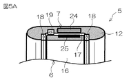
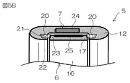
図3は、推進ユニット5の部分断面図である。図4は、推進ユニット5の背面図である。図5Aおよび図5Bは、推進ユニット5の外周部の断面図である。
図3に示すように、推進ユニット5は、前述のプロペラ6および電動モータ7と、プロペラ軸線A2まわりにプロペラ6を取り囲む円筒状のダクト12と、電動モータ7を制御するモータECU13と、電動モータ7の回転角を検出するモータ回転角検出装置14とを含む。ダクト12は、前後方向に延びる姿勢でステアリングシャフト4に連結されている。モータECU13は、ステアリングシャフト4の内部に配置されていてもよいし、船内に配置されていてもよい。モータ回転角検出装置14は、ダクト12の内部に配置されている。プロペラ6は、ダクト12によって保持されている。プロペラ6およびダクト12は、同軸的に配置されている。
FIG. 3 is a partial cross-sectional view of the
As shown in FIG. 3, the
図3に示すように、プロペラ6は、プロペラ軸線A2まわりに回転可能な複数の羽根15(blade)と、複数の羽根15を取り囲む円筒状のリム16とを含む。複数の羽根15は、間隔を空けてプロペラ6の周方向に配列されている。図4に示すように、羽根15は、リム16の内周面からプロペラ軸線A2に向かって延びる略三角形状である。羽根15は、平らなプレートであってもよいし、曲線部を含む湾曲したプレートであってもよい。羽根15の外端部(リム16側の端部)は、リム16に固定されている。したがって、羽根15およびリム16は、プロペラ軸線A2まわりに一体回転可能である。
As shown in FIG. 3, the
図3に示すように、リム16は、ダクト12の内側でプロペラ軸線A2を取り囲んでいる。リム16およびダクト12の中心軸線は、プロペラ軸線A2上に配置されている。図5Aおよび図5Bに示すように、リム16は、ダクト12の内周部に設けられた環状溝17に収容されている。環状溝17は、ダクト12の内周面より凹んでおり、全周に亘って連続している。リム16は、環状溝17内に収容された状態で、ダクト12に対してプロペラ軸線A2まわりに回転可能である。したがって、プロペラ6は、ダクト12に対してプロペラ軸線A2まわりに回転可能である。
As shown in FIG. 3, the
リム16は、複数のベアリングを介してダクト12に保持されている。図5Aに示すように、リム16は、2つのスラストベアリング18とラジアルベアリング19とを介してダクト12に保持されていてもよい。また、図5Bに示すように、リム16は、複数のテーパローラベアリング20を介してダクト12に保持されていてもよい。スラストベアリング18およびラジアルベアリング19は、ボールベアリングであってもよいし、ローラベアリングであってもよいし、その他の形式のベアリングであってもよい。
The
図5Aに示すように、前側のスラストベアリング18は、リム16の前端面とダクト12との間に配置されており、後側のスラストベアリング18は、リム16の後端面とダクト12との間に配置されている。ラジアルベアリング19は、リム16の外周面とダクト12との間に配置されている。2つのスラストベアリング18は、プロペラ軸線A2まわりにリム16を回転可能に支持すると共に、軸方向(プロペラ軸線A2に沿う方向)へのリム16の移動量を規制する。ラジアルベアリング19は、プロペラ軸線A2まわりにリム16を回転可能に支持すると共に、径方向へのリム16の移動量を規制する。したがって、軸方向および径方向へのプロペラ6の移動量は、スラストベアリング18およびラジアルベアリング19によって規制される。
As shown in FIG. 5A, the front thrust bearing 18 is disposed between the front end surface of the
一方、複数のテーパローラベアリング20は、複数の対を構成している。図4および図5Bを併せて参照すると分かるように、対のテーパローラベアリング20は、前後方向から見たときに重なるように前後に間隔を空けて配置されている。図5Bに示すように、前側のテーパローラベアリング20は、リム16の前端面とダクト12との間に配置されており、後側のテーパローラベアリング20は、リム16の後端面とダクト12との間に配置されている。図4に示すように、複数の対のテーパローラベアリング20は、間隔を空けて周方向に配列されている。
On the other hand, the plurality of tapered
図5Bに示すように、テーパローラベアリング20は、ダクト12によって保持された支持軸21と、支持軸21を取り囲む内輪22と、内輪22の周囲に配置された複数のローラ23とを含む。複数のローラ23は、図示しない環状の保持器(retainer)によって保持されている。各ローラ23は、自身の中心軸線まわりに回転しながら(自転しながら)、内輪22まわりに回転可能である。各ローラ23は、リム16の前端面または後端面に接している。テーパローラベアリング20は、プロペラ軸線A2まわりにリム16を回転可能に支持すると共に、軸方向および径方向へのリム16の移動量を規制する。したがって、軸方向および径方向へのプロペラ6の移動量は、テーパローラベアリング20によって規制される。
As shown in FIG. 5B, the tapered
図6Aおよび図6Bは、電動モータ7の一部の断面図である。以下では、図5A〜図6Bを参照して、電動モータ7について説明する。
図5Aおよび図5Bに示すように、電動モータ7は、ダクト12の一部によって構成された環状のステータ24と、リム16の一部によって構成された円筒状のロータ25とを含む。すなわち、ダクト12は、ダクト12の外周面と環状溝17の底面との間に配置されたステータ24を含み、リム16は、リム16の外周部に設けられたロータ25を含む。ステータ24およびロータ25は、プロペラ軸線A2を取り囲んでいる。ステータ24およびロータ25は、間隔を空けてプロペラ6の径方向に対向している。図6Aおよび図6Bに示すように、ステータ24は、電磁鋼板などの軟磁性材料によって形成された環状のステータコア26と、ステータコア26に巻回された複数のコイル27とを含む。
6A and 6B are partial cross-sectional views of the
As shown in FIGS. 5A and 5B, the
図6Aに示すように、ロータ25は、軟磁性材料によって形成された円筒状のロータコア28と、ロータコア28に保持された複数のマグネット29とを含む永久磁石型ロータ(permanent-magnet rotor)であってもよい。すなわち、電動モータ7は、永久磁石型直流モータであってもよい。また、図6Bに示すように、ロータ25は、間隔を空けてプロペラ6の周方向に配列された複数の突極30(salient pole)を含んでおり、軟磁性材料によって形成された円筒状の突極型ロータ(salient poled rotor)であってもよい。すなわち、電動モータ7は、スイッチドリラクタンスモータ(switched reluctance motor)であってもよい。電動モータ7は、これらのモータに限らず、ブラシ付きの直流モータであってもよいし、ブラシレスモータであってもよいし、その他の形式のモータであってもよい。
As shown in FIG. 6A, the
図6Aに示すように、複数のコイル27は、プロペラ6の周方向に配列されている。複数のコイル27は、プロペラ軸線A2を取り囲む環状列を構成している。同様に、複数のマグネット29は、プロペラ6の周方向に配列されており、プロペラ軸線A2を取り囲む環状列を構成している。複数のコイル27は、プロペラ軸線A2を取り囲むと共に、プロペラ6の軸方向に並んだ複数の環状列を構成していてもよい。同様に、複数のマグネット29は、プロペラ軸線A2を取り囲むと共に、プロペラ6の軸方向に並んだ複数の環状列を構成していてもよい。たとえば、巻き数が半分に減らされた複数のコイル27によって、プロペラ6の軸方向に並んだ2つの環状列が構成されていてもよい。この構成によれば、電動モータ7の最大出力の変化を抑制しながら、径方向への電動モータ7の厚みを減少させることができる。
As shown in FIG. 6A, the plurality of
電動モータ7は、ステータ24によってロータ25をプロペラ軸線A2まわりに回転させることにより、ダクト12に対してリム16をプロペラ軸線A2まわりに回転させる。これにより、複数の羽根15が、ダクト12に対してプロペラ軸線A2まわりに回転する。電動モータ7は、正転および逆転可能である。電動モータ7が正転方向にロータ25を回転させると、プロペラ6も正転方向に回転し、前進方向の推力が発生する。これとは反対に、電動モータ7がロータ25を逆転方向に回転させると、プロペラ6も逆転方向に回転し、後進方向の推力が発生する。モータECU13(図3参照)は、出力調整装置10(図1A参照)から入力された出力指令に基づいてステータ24への電力供給を制御する。すなわち、モータECU13は、モータ回転角検出装置14(図3参照)からの出力に基づいてステータ24への電力供給を制御することにより、ロータ25の回転方向および回転速度を制御する。これにより、出力指令に基づく方向および速度で船舶V1が推進される。
The
図7Aおよび図7Bは、推進ユニット5の断面図である。図8Aおよび図8Bは、図4に示すVIII−VIII線に沿う羽根15の断面図である。
図7Aに示すように、ダクト12の前端部の内径は、ダクト12の後端部の内径と等しくてもよい。この場合、図8Aに示すように、羽根15の断面は、直線状であってもよい。この構成によれば、プロペラ6の回転速度が同じであれば、推進ユニット5は、前進方向への推力とほぼ同じ大きさの後進方向への推力を発生できる。
7A and 7B are cross-sectional views of the
As shown in FIG. 7A, the inner diameter of the front end portion of the
一方、図7Bに示すように、ダクト12の前端部の内径IDfは、ダクト12の後端部の内径IDrより大きくてもよい。この場合、図8Bに示すように、羽根15の断面は、前方に凸の円弧状であってもよい。この構成によれば、ダクト12の後端部の流路面積が、ダクト12の前端部の流路面積より小さいので、ダクト12を前から後に通過する水流がダクト12によって加速される。これにより、より大きな前進方向への推力が発生する。さらに、羽根15の断面が、円弧状であるので、推進効率が高まる。
On the other hand, as shown in FIG. 7B, the inner diameter IDf of the front end portion of the
以上のように第1実施形態では、プロペラ6の複数の羽根15が、プロペラ6のリム16によって取り囲まれている。リム16は、ダクト12によって取り囲まれている。ダクト12は、プロペラ6を保持している。ダクト12は、ステアリングシャフト4と共にステアリング軸線A1まわりに回転可能である。ステアリングシャフト4が、ステアリング軸線A1まわりに操舵されると、プロペラ6は、ダクト12と共にステアリング軸線A1まわりに回転する。リム16は、ダクト12に対して複数の羽根15と共にプロペラ軸線A2まわりに回転可能である。したがって、電動モータ7がダクト12に対してリム16を回転させると、複数の羽根15が、ダクト12に対してプロペラ軸線A2まわりに回転する。これにより、水流が形成され、船舶V1が推進される。
As described above, in the first embodiment, the plurality of
電動モータ7は、プロペラ軸線A2に対して複数の羽根15より外方に配置されている。したがって、電動モータ7がプロペラ6の前または後に配置されている場合よりもプロペラ6の有効面積が広く、推進効率が高い。さらに、電動モータ7がプロペラ6の前または後に配置されている場合よりも、水中に配置される船舶推進装置1の水中部分の前後方向への長さが小さいので、操舵時に水中部分が水から受ける抵抗が小さい。そのため、操舵荷重を低減でき、高出力のモータを電動モータ7として用いることができる。しかも、電動モータ7全体が水中に配置されるので、モータ音が乗船者に伝わり難い。そのため、船舶推進装置1の静粛性を高めることができる。
The
さらに、電動モータがプロペラの前または後に配置されている従来の船舶推進装置よりも推進効率が高まるので、電動モータ7の消費電力を低減できる。さらに、電動モータ7全体が水中に配置されるので、電動モータ7が空中に配置されている場合よりも、電動モータ7の温度上昇を抑制できる。したがって、温度の上昇に伴う電動モータ7の電気抵抗の上昇を抑制できる。そのため、電動モータ7の消費電力をさらに低減できる。これにより、船舶推進装置1の稼働時間および船舶V1の航走距離を増加させることができる。もしくは、船舶推進装置1の稼働時間および船舶V1の航走距離を減少させずに、バッテリー9の容量を低減できる。これにより、船舶V1に積載される積載物の重量を低減できる。
Furthermore, since the propulsion efficiency is higher than that of the conventional marine vessel propulsion device in which the electric motor is disposed before or after the propeller, the power consumption of the
[第2実施形態]
次に、この発明の第2実施形態について説明する。
この第2実施形態と前述の第1実施形態との主要な相違点は、プロペラの中心部に回転軸が設けられていることである。
図9は、この発明の第2実施形態に係る推進ユニット205の背面図である。図10Aおよび図10Bは、図9に示すX−X線に沿う推進ユニット205の断面図である。図9〜図10Bにおいて、前述の図1〜図8Bに示された各部と同等の構成部分については、図1等と同一の参照符号を付してその説明を省略する。
[Second Embodiment]
Next explained is the second embodiment of the invention.
The main difference between the second embodiment and the first embodiment described above is that a rotating shaft is provided at the center of the propeller.
FIG. 9 is a rear view of the
第2実施形態に係る推進ユニット205は、プロペラ6を除き、第1実施形態に係る推進ユニット5と同様の構成を備えている。すなわち、推進ユニット205は、第1実施形態に係るプロペラ6に代えて、プロペラ206を含む。
図9に示すように、プロペラ206は、ダクト12によって保持されている。プロペラ206およびダクト12は、同軸的に配置されている。プロペラ206は、複数の羽根15と、リム16とを含む。図10Aおよび図10Bに示すように、プロペラ206は、さらに、プロペラ軸線A2に沿って前後方向に延びる筒状の回転軸231と、回転軸231を前後方向に貫通する中心軸232とを含む。羽根15の内端部(リム16とは反対側の端部)は、回転軸231に固定されている。回転軸231は、一体回転可能に中心軸232に連結されている。回転軸231は、中心軸232と共にプロペラ軸線A2まわりに回転する。したがって、回転軸231は、羽根15、リム16、および中心軸232と共にプロペラ軸線A2まわりに一体回転可能である。中心軸232は、プロペラ軸線A2に沿って前後方向に延びている。中心軸232の前端部および後端部は、回転軸231から突出している。
The
As shown in FIG. 9, the
図10Aおよび図10Bに示すように、推進ユニット205は、さらに、複数のベアリングを介して中心軸232の前端部および後端部をそれぞれ支持する前側固定軸233および後側固定軸234と、前側固定軸233および後側固定軸234とダクト12とを連結する複数の固定羽根235とを含む。プロペラ206は、前側固定軸233、後側固定軸234、および固定羽根235を介して、プロペラ軸線A2まわりに回転可能にダクト12に保持されている。したがって、リム16は、図5Aおよび図5Bに示すベアリング18、19、20を介してダクト12に保持されていてもよいし、ベアリング18、19、20を介してダクト12に保持されていなくてもよい。
As shown in FIGS. 10A and 10B, the
前側固定軸233および後側固定軸234は、プロペラ軸線A2に沿って前後方向に延びている。前側固定軸233および後側固定軸234は、回転軸231と概ね等しい外径を有する円柱状である。前側固定軸233の前端部は、前方に凸の半球状であり、後側固定軸234の後端部は、後方に凸の半球状である。固定羽根235は、前側固定軸233または後側固定軸234から径方向外方に延びている。固定羽根235は、径方向に延びる平らなプレートであってもよいし、曲線部を含む湾曲したプレートであってもよい。図9に示すように、固定羽根235の外端部は、ダクト12に固定されており、固定羽根235の内端部は、前側固定軸233または後側固定軸234に固定されている。したがって、前側固定軸233および後側固定軸234は、ダクト12に固定されており、ダクト12に対して回転不能である。
The front fixed
図10Aおよび図10Bに示すように、中心軸232の前端部および後端部は、それぞれ、前側固定軸233および後側固定軸234の内部に配置されている。図10Aに示すように、中心軸232は、2つのスラストベアリング218と2つのラジアルベアリング219とを介して前側固定軸233および後側固定軸234に支持されていてもよい。また、図10Bに示すように、中心軸232は、2つのテーパローラベアリング220を介して前側固定軸233および後側固定軸234に支持されていてもよい。
As shown in FIGS. 10A and 10B, the front end portion and the rear end portion of the
図10Aに示すように、スラストベアリング218およびラジアルベアリング219は、前側固定軸233または後側固定軸234の内部に配置されている。前側固定軸233および後側固定軸234の内部には、潤滑油などの潤滑剤が充填されている。中心軸232と前側固定軸233および後側固定軸234と間は、前側固定軸233または後側固定軸234に保持された環状のシール236によって密閉されている。前側のシール236は、前側のスラストベアリング218およびラジアルベアリング219より後方に配置されており、後側のシール236は、後側のスラストベアリング218およびラジアルベアリング219より前方に配置されている。前側のスラストベアリング218およびラジアルベアリング219は、中心軸232の前端部と前側固定軸233との間に配置されており、後側のスラストベアリング218およびラジアルベアリング219は、中心軸232の後端部と後側固定軸234との間に配置されている。
As shown in FIG. 10A, the
図10Aに示すように、2つのスラストベアリング218は、中心軸232の前後に配置されており、2つのラジアルベアリング219は、プロペラ軸線A2まわりに中心軸232を取り囲んでいる。2つのスラストベアリング218は、プロペラ軸線A2まわりに中心軸232を回転可能に支持すると共に、軸方向への中心軸232の移動量を規制する。ラジアルベアリング219は、プロペラ軸線A2まわりに中心軸232を回転可能に支持すると共に、径方向への中心軸232の移動量を規制する。したがって、軸方向および径方向へのプロペラ206の移動量は、スラストベアリング218およびラジアルベアリング219によって規制される。
As shown in FIG. 10A, the two
一方、図10Bに示すように、2つのテーパローラベアリング220は、それぞれ、前側固定軸233および後側固定軸234の内部に配置されている。前側固定軸233および後側固定軸234の内部には、潤滑剤が充填されている。中心軸232と前側固定軸233および後側固定軸234と間は、中心軸232に保持された環状のシール237によって密閉されている。前側のシール237は、前側のテーパローラベアリング220より後方に配置されており、後側のシール237は、後側のテーパローラベアリング220より前方に配置されている。前側のテーパローラベアリング220は、前側固定軸233の内部で中心軸232を取り囲んでおり、後側のテーパローラベアリング220は、後側固定軸234の内部で中心軸232を取り囲んでいる。さらに、前側のテーパローラベアリング220は、軸方向に関して、前側固定軸233と回転軸231との間に配置されており、後側のテーパローラベアリング220は、軸方向に関して、後側固定軸234と回転軸231との間に配置されている。
On the other hand, as shown in FIG. 10B, the two tapered
図10Bに示すように、テーパローラベアリング20は、中心軸232を取り囲む内輪22と、内輪22の周囲に配置された複数のローラ23と、複数のローラ23の周囲に配置された外輪238とを含む。外輪238は、中心軸232に保持されている。外輪238は、中心軸232と共にプロペラ軸線A2まわりに回転する。各ローラ23は、外輪238に接している。テーパローラベアリング220は、プロペラ軸線A2まわりに中心軸232を回転可能に支持すると共に、軸方向および径方向への中心軸232の移動量を規制する。したがって、軸方向および径方向へのプロペラ206の移動量は、テーパローラベアリング220によって規制される。
As shown in FIG. 10B, the tapered
この推進ユニット205では、プロペラ206が正転方向に回転すると、前方からダクト12内に水が吸い込まれると共に、ダクト12内に吸い込まれた水が、プロペラ206から後方に送られる。プロペラ206から後方に送られた水は、プロペラ206の後方に配置されている複数の固定羽根235の間を通過した後、ダクト12から後方に排出される。水流が複数の固定羽根235の間を通過することにより、プロペラ6の回転によって生じた水流のねじれが低減され、水流が整えられる。プロペラ206が逆転方向に回転した場合も同様に、水流が、プロペラ206の前方に配置されている複数の固定羽根235の間を通過することにより、水流のねじれが低減される。このように、ダクト12内を流れる水は、複数の固定羽根235によって整流される。すなわち、複数の羽根15は、動翼として機能し、複数の固定羽根235は、静翼として機能する。
In this
[第3実施形態]
次に、この発明の第3実施形態について説明する。
この第3実施形態と前述の第1実施形態との主要な相違点は、電動モータの動力が、歯車伝達機構を介してリムに伝達されることである。
図11は、この発明の第3実施形態に係る推進ユニット305の部分断面図である。図12は、この発明の第3実施形態に係る推進ユニット305の外周部の断面図である。図11〜図12において、前述の図1〜図10Bに示された各部と同等の構成部分については、図1等と同一の参照符号を付してその説明を省略する。
[Third Embodiment]
Next explained is the third embodiment of the invention.
The main difference between the third embodiment and the first embodiment described above is that the power of the electric motor is transmitted to the rim via a gear transmission mechanism.
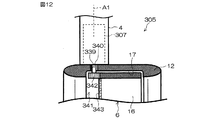
FIG. 11 is a partial cross-sectional view of a
第3実施形態に係る推進ユニット305は、電動モータ7を除き、第1実施形態に係る推進ユニット5と同様の構成を備えている。すなわち、推進ユニット305は、第1実施形態に係る電動モータ7に代えて、ステアリングシャフト4の内部に配置された電動モータ307を含む。電動モータ307は、ダクト12の上方に配置されている。電動モータ307は、モータECU13によって制御される。図12に示すように、電動モータ307は、ダクト12を径方向に貫通する貫通孔339に挿入されたモータ軸340を含む。モータ軸340の先端部は、環状溝17内に配置されている。
The
推進ユニット305は、さらに、電動モータ307の動力をリム16に伝達する歯車伝達機構341を含む。歯車伝達機構341は、モータ軸340に連結された駆動ギヤ342と、リム16の前端面に形成された従動ギヤ343とを含む。駆動ギヤ342は、平歯車または斜歯歯車であり、従動ギヤ343は、正面歯車(face gear)である。駆動ギヤ342および従動ギヤ343は、互いに噛み合っていてもよいし、共通の中間ギヤに噛み合っていてもよい。図11および図12では、駆動ギヤ342が、従動ギヤ343に噛み合っている状態が示されている。駆動ギヤ342は、モータ軸340と共に回転し、従動ギヤ343は、リム16と共に回転する。電動モータ307の回転は、歯車伝達機構341によって減速された状態でリム16に伝達される。これにより、電動モータ307の動力が増幅された状態でリム16に伝達され、プロペラ6が、ダクト12に対してプロペラ軸線A2まわりに回転する。
The
[第4実施形態]
次に、この発明の第4実施形態について説明する。
この第4実施形態と前述の第1実施形態との主要な相違点は、プロペラが、二重反転プロペラであることである。
図13は、この発明の第4実施形態に係る推進ユニット405の部分断面図である。図14は、この発明の第4実施形態に係る推進ユニット405の外周部の断面図である。図13〜図14において、前述の図1〜図12に示された各部と同等の構成部分については、図1等と同一の参照符号を付してその説明を省略する。
[Fourth Embodiment]
Next explained is the fourth embodiment of the invention.
The main difference between the fourth embodiment and the first embodiment described above is that the propeller is a counter-rotating propeller.
FIG. 13 is a partial sectional view of a
第4実施形態に係る推進ユニット405は、推力を発生するプロペラ406と、プロペラ軸線A2まわりにプロペラ406を回転させる電動モータ407とを含む。さらに、推進ユニット405は、プロペラ軸線A2まわりにプロペラ406を取り囲む円筒状のダクト12と、電動モータ407を制御するモータECU13と、電動モータ407の回転角を検出するモータ回転角検出装置14とを含む。プロペラ406は、ダクト12によって保持されている。プロペラ406およびダクト12は、同軸的に配置されている。
The
図13に示すように、プロペラ406は、前後に配置された前側プロペラ444および後側プロペラ445を含む。前側プロペラ444および後側プロペラ445は、ダクト12と同軸である。前側プロペラ444および後側プロペラ445は、共通の軸線(プロペラ軸線A2)まわりに回転可能にダクト12に保持されている。前側プロペラ444および後側プロペラ445は、二重反転プロペラを構成している。すなわち、前側プロペラ444は、正転方向に回転することにより前進方向への推力を発生し、逆転方向に回転することにより後進方向への推力を発生する。一方、後側プロペラ445は、逆転方向に回転することにより前進方向への推力を発生し、正転方向に回転することにより後進方向への推力を発生する。
As shown in FIG. 13, the
図13に示すように、前側プロペラ444は、プロペラ軸線A2まわりに回転可能な複数の前側羽根446と、複数の前側羽根446を取り囲んでおり複数の前側羽根446と共にプロペラ軸線A2まわりに回転可能な筒状の前側リム447とを含む。同様に、後側プロペラ445は、プロペラ軸線A2まわりに回転可能な複数の後側羽根448と、複数の後側羽根448を取り囲んでおり複数の後側羽根448と共にプロペラ軸線A2まわりに回転可能な筒状の後側リム449とを含む。前側リム447および後側リム449は、前後に配置されている。前側リム447および後側リム449は、互いに等しい形状を有している。すなわち、前側リム447の外径は、後側リム449の外径と等しく、前側リム447の内径は、後側リム449の内径の外径と等しい。さらに、前側リム447の軸長(前後方向への長さ)は、後側リム449の軸長と等しい。
As shown in FIG. 13, the
図13に示すように、複数の前側羽根446は、間隔を空けてプロペラ406の周方向に配列されている。前側羽根446は、前側リム447の内周面からプロペラ軸線A2に向かって延びる略三角形状である。前側羽根446の外端部は、前側リム447に固定されている。したがって、前側羽根446および前側リム447は、プロペラ軸線A2まわりに一体回転可能である。前側リム447は、ダクト12の内側でプロペラ軸線A2を取り囲んでいる。前側リム447およびダクト12の中心軸線は、プロペラ軸線A2上に配置されている。
As shown in FIG. 13, the plurality of
図14に示すように、前側リム447は、ダクト12の内周部に設けられた前側環状溝450に収容されている。前側環状溝450は、ダクト12の内周面より凹んでおり、全周に亘って連続している。前側リム447は、前側環状溝450内に収容された状態で、ダクト12に対してプロペラ軸線A2まわりに回転可能である。したがって、前側プロペラ444は、ダクト12に対してプロペラ軸線A2まわりに回転可能である。
As shown in FIG. 14, the
一方、図13に示すように、複数の後側羽根448は、間隔を空けてプロペラ406の周方向に配列されている。後側羽根448は、後側リム449の内周面からプロペラ軸線A2に向かって延びる略三角形状である。後側羽根448の外端部は、後側リム449に固定されている。したがって、後側羽根448および後側リム449は、プロペラ軸線A2まわりに一体回転可能である。後側リム449は、ダクト12の内側でプロペラ軸線A2を取り囲んでいる。後側リム449およびダクト12の中心軸線は、プロペラ軸線A2上に配置されている。
On the other hand, as shown in FIG. 13, the plurality of
図14に示すように、後側リム449は、ダクト12の内周部に設けられた後側環状溝451に収容されている。後側環状溝451は、ダクト12の内周面より凹んでおり、全周に亘って連続している。後側リム449は、後側環状溝451内に収容された状態で、ダクト12に対してプロペラ軸線A2まわりに回転可能である。したがって、後側プロペラ445は、ダクト12に対してプロペラ軸線A2まわりに回転可能である。
As shown in FIG. 14, the
図14に示すように、電動モータ407は、プロペラ軸線A2まわりに前側リム447を回転させる前側電動モータ452と、プロペラ軸線A2まわりに後側リム449を回転させる後側電動モータ453とを含む。前側電動モータ452および後側電動モータ453は、モータECU13によって制御される。前側電動モータ452および後側電動モータ453は、同種のモータであってもよいし、異なる種類のモータであってもよい。
As shown in FIG. 14, the
図14に示すように、前側電動モータ452は、ダクト12の一部によって構成された環状の前側ステータ454と、前側リム447の一部によって構成された円筒状の前側ロータ455とを含む。すなわち、ダクト12は、ダクト12の外周面と前側環状溝450の底面との間に配置された前側ステータ454を含み、前側リム447は、前側リム447の外周部に設けられた前側ロータ455を含む。前側ステータ454および前側ロータ455は、プロペラ軸線A2を取り囲んでいる。前側ステータ454および前側ロータ455は、間隔を空けてプロペラ406の径方向に対向している。前側ステータ454に対する前側ロータ455の回転角は、モータ回転角検出装置14によって検出される。
As shown in FIG. 14, the front
同様に、図14に示すように、後側電動モータ453は、ダクト12の一部によって構成された環状の後側ステータ456と、後側リム449の一部によって構成された円筒状の後側ロータ457とを含む。すなわち、ダクト12は、ダクト12の外周面と後側環状溝451の底面との間に配置された後側ステータ456を含み、後側リム449は、後側リム449の外周部に設けられた後側ロータ457を含む。後側ステータ456および後側ロータ457は、プロペラ軸線A2を取り囲んでいる。後側ステータ456および後側ロータ457は、間隔を空けてプロペラ406の径方向に対向している。前側ステータ454に対する前側ロータ455の回転角は、モータ回転角検出装置14によって検出される。
Similarly, as shown in FIG. 14, the rear
前側電動モータ452は、ダクト12に対して前側リム447をプロペラ軸線A2まわりに回転させることにより、複数の前側羽根446をプロペラ軸線A2まわりに回転させる。同様に、後側電動モータ453は、ダクト12に対して後側リム449をプロペラ軸線A2まわりに回転させることにより、複数の後側羽根448をプロペラ軸線A2まわりに回転させる。モータECU13は、前側電動モータ452および後側電動モータ453を制御することにより、前側プロペラ444を正転方向に回転させると共に、前側プロペラ444と同じ回転速度で後側プロペラ445を逆転方向に回転させる。これにより、前進方向への推力が発生する。同様に、モータECU13は、前側電動モータ452および後側電動モータ453を制御することにより、前側プロペラ444を逆転方向に回転させると共に、前側プロペラ444と同じ回転速度で後側プロペラ445を正転方向に回転させる。これにより、後進方向への推力が発生する。
The front
[第5実施形態]
次に、この発明の第5実施形態について説明する。
この第5実施形態と前述の第4実施形態との主要な相違点は、電動モータの動力が、歯車伝達機構を介してリムに伝達されることである。
図15は、この発明の第5実施形態に係る推進ユニット505の部分断面図である。図16は、この発明の第5実施形態に係る推進ユニット505の外周部の断面図である。図15〜図16において、前述の図1〜図14に示された各部と同等の構成部分については、図1等と同一の参照符号を付してその説明を省略する。
[Fifth Embodiment]
Next explained is the fifth embodiment of the invention.
The main difference between the fifth embodiment and the fourth embodiment described above is that the power of the electric motor is transmitted to the rim via the gear transmission mechanism.
FIG. 15 is a partial sectional view of a
第5実施形態に係る推進ユニット505は、電動モータ407を除き、第4実施形態に係る推進ユニット405と同様の構成を備えている。すなわち、推進ユニット505は、第4実施形態に係る電動モータ407に代えて、ステアリングシャフト4の内部に配置された電動モータ307を含む。さらに、推進ユニット505は、電動モータ307の動力をリム16に伝達する歯車伝達機構541を含む。
The
図16に示すように、歯車伝達機構541は、電動モータ307のモータ軸340に連結された駆動ギヤ342と、前側リム447の後端面に形成された前側従動ギヤ558と、後側リム449の前端面に形成された後側従動ギヤ559とを含む。駆動ギヤ342は、平歯車または斜歯歯車であり、前側従動ギヤ558および後側従動ギヤ559は、正面歯車である。駆動ギヤ342および前側従動ギヤ558は、互いに噛み合っていてもよいし、共通の中間ギヤに噛み合っていてもよい。駆動ギヤ342および後側従動ギヤ559についても同様である。図15および図16では、駆動ギヤ342が、前側リム447と後側リム449との間に配置されており、前側従動ギヤ558および後側従動ギヤ559の両方に噛み合っている状態が示されている。
As shown in FIG. 16, the
駆動ギヤ342は、モータ軸340と共に回転する。前側従動ギヤ558および後側従動ギヤ559は、それぞれ、前側リム447および後側リム449と共に回転する。駆動ギヤ342および前側従動ギヤ558の減速比は、駆動ギヤ342および後側従動ギヤ559の減速比と等しい。したがって、駆動ギヤ342が回転すると、前側リム447および後側リム449は、互いに反対の方向に同じ回転速度で回転する。電動モータ307の回転は、歯車伝達機構541によって減速された状態で前側リム447および後側リム449に伝達される。これにより、電動モータ307の動力が増幅された状態で前側リム447および後側リム449に伝達され、前側プロペラ444および後側プロペラ445が、ダクト12に対して互いに反対の方向に回転する。
The
[第6実施形態]
次に、この発明の第6実施形態について説明する。
この第6実施形態と前述の第4実施形態との主要な相違点は、プロペラのピッチ(プロペラが一回転して進む距離)が変更可能であり、プロペラの外周部で前側リムおよび後側リムの相対回転量を規制する外周側規制部が設けられていることである。
[Sixth Embodiment]
Next, a sixth embodiment of the invention will be described.
The main difference between the sixth embodiment and the fourth embodiment described above is that the pitch of the propeller (the distance traveled by one rotation of the propeller) can be changed, and the front rim and the rear rim at the outer periphery of the propeller. The outer peripheral side restricting part for restricting the relative rotation amount is provided.
図17は、この発明の第6実施形態に係る推進ユニット605の断面図である。図18Aおよび図18Bは、プロペラ軸線A2に対する羽根15の傾き角度について説明するための図である。図17〜図18Bにおいて、前述の図1〜図16に示された各部と同等の構成部分については、図1等と同一の参照符号を付してその説明を省略する。
第6実施形態に係る推進ユニット605は、プロペラ406を除き、第4実施形態に係る推進ユニット405と同様の構成を備えている。すなわち、推進ユニット605は、第4実施形態に係るプロペラ406に代えて、プロペラ606を含む。
FIG. 17 is a sectional view of a
The
図17に示すように、プロペラ606は、プロペラ軸線A2まわりに回転可能な複数の羽根15と、複数の羽根15を取り囲む円筒状の前側リム447と、前側リム447の後方で複数の羽根15を取り囲む後側リム449とを含む。図17〜図18Bでは、1つの羽根15だけを図示しており、他の羽根15の図示を省略している。各羽根15は、前側リム447および後側リム449によって支持されている。前側リム447および後側リム449は、プロペラ軸線A2まわりに相対回転可能にダクト12に保持されている。
As shown in FIG. 17, the
図17に示すように、推進ユニット605は、前側リム447および後側リム449の相対回転量を規制する外周側規制部660をさらに含む。外周側規制部660は、羽根15の前端部に設けられた前側被支持部661と、前側リム447に設けられた前側支持部662とを含む。さらに、外周側規制部660は、羽根15の後端部に設けられた後側被支持部663と、後側リム449に設けられた後側支持部664とを含む。前側支持部662は、前側リム447の内周面に配置されており、後側支持部664は、後側リム449の内周面に配置されている。前側支持部662は、前側リム447の内周面から突出する棒状の突起であり、後側支持部664は、後側リム449の内周面から突出する棒状の突起である。前側支持部662は、前側被支持部661によって区画された前側挿入孔665内に挿入されている。同様に、後側支持部664は、後側被支持部663によって区画された後側挿入孔666内に挿入されている。
As shown in FIG. 17, the
図17に示すように、前側挿入孔665は、プロペラ軸線A2に対して傾いた方向(長手方向)に延びる長孔であり、後側挿入孔666は、概ね円形である。前側被支持部661は、前側支持部662まわりに回転可能に前側支持部662に支持されている。同様に、後側被支持部663は、後側支持部664まわりに回転可能に後側支持部664に支持されている。さらに、前側挿入孔665が長孔であるから、前側被支持部661は、前側支持部662に対して、前側挿入孔665の長手方向に移動可能である。前側支持部662に対する前側被支持部661の移動量は、前側支持部662と前側被支持部661(前側挿入孔665の内面)との接触によって規制される。
As shown in FIG. 17, the
図18Aおよび図18Bにおいて黒と白の矢印で示すように、前側リム447および後側リム449がプロペラ軸線A2まわりに相対回転すると、前側被支持部661が、前側支持部662に対して前側挿入孔665の長手方向に移動する。このとき、後側被支持部663は、後側支持部664に対して後側支持部664まわりに回転する。そのため、プロペラ軸線A2に対する羽根15の傾き角度が変化する。羽根15の傾き角度の変化量は、前側リム447および後側リム449の相対回転量の増加に伴って増加する。そして、前側リム447および後側リム449の相対回転量が所定値に達すると、前側挿入孔665の内面が、前側支持部662に接触し、前側リム447および後側リム449の相対回転が規制される。これにより、前側リム447および後側リム449の相対回転量が規制される。
When the
前側リム447は、前側電動モータ452(図17参照)によってプロペラ軸線A2まわりに回転駆動され、後側リム449は、後側電動モータ453(図17参照)によってプロペラ軸線A2まわりに回転駆動される。図18Aにおいて黒と白の矢印で示すように、モータECU13は、前側電動モータ452および後側電動モータ453を制御することにより、前側リム447および後側リム449の位相が一致した状態で(同位相の状態で)、前側リム447および後側リム449を回転させる。また、図18Bにおいて黒と白の矢印で示すように、モータECU13は、前側電動モータ452および後側電動モータ453を制御することにより、前側リム447の位相が後側リム449の位相より進んだ状態で(前側リム447が進角した状態で)、前側リム447および後側リム449を回転させる。
The
図18Aに示すように、前側リム447および後側リム449の位相が一致した状態で、前側リム447および後側リム449が回転すると、前側支持部662が前側被支持部661に対して後側に偏った状態で、各羽根15が、前側リム447および後側リム449と共にプロペラ軸線A2まわりに回転する。また、図18Bに示すように、前側リム447の位相が後側リム449の位相より進んだ状態で、前側リム447および後側リム449が回転すると、前側支持部662が前側被支持部661に対して前側に偏った状態で、各羽根15が、前側リム447および後側リム449と共にプロペラ軸線A2まわりに回転する。
As shown in FIG. 18A, when the
図18Aおよび図18Bを比較すると分かるように、前側リム447および後側リム449の位相が一致している状態と、前側リム447の位相が後側リム449の位相より進んでいる状態とでは、プロペラ軸線A2に対する羽根15の傾き角度が異なっている。プロペラ606のピッチは、プロペラ軸線A2に対する羽根15の傾き角度に応じて変化する。したがって、モータECU13は、前側リム447および後側リム449の位相を制御することにより、前側リム447および後側リム449が相対回転できる範囲内でプロペラ606のピッチを調整できる。そのため、モータECU13は、プロペラ606の特性を高トルク型と高出力型との間で変化させることができる。
As can be seen by comparing FIG. 18A and FIG. 18B, in the state where the phases of the
[第7実施形態]
次に、この発明の第7実施形態について説明する。
この第7実施形態と前述の第4実施形態との主要な相違点は、プロペラのピッチが変更可能であり、プロペラの中心部で前側リムおよび後側リムの相対回転量を規制する中心側規制部が設けられていることである。
[Seventh Embodiment]
Next explained is the seventh embodiment of the invention.
The main difference between the seventh embodiment and the fourth embodiment described above is that the pitch of the propeller can be changed, and the center side regulation that regulates the relative rotation amount of the front rim and the rear rim at the center of the propeller. Part is provided.
図19は、この発明の第7実施形態に係る推進ユニット705の断面図である。図20Aおよび図20Bは、プロペラ軸線A2に対する羽根15の傾き角度について説明するための図である。図19〜図20Bにおいて、前述の図1〜図18Bに示された各部と同等の構成部分については、図1等と同一の参照符号を付してその説明を省略する。
第7実施形態に係る推進ユニット705は、プロペラ406を除き、第4実施形態に係る推進ユニット405と同様の構成を備えている。すなわち、推進ユニット705は、第4実施形態に係るプロペラ406に代えて、プロペラ706を含む。
FIG. 19 is a sectional view of a
The
図19に示すように、プロペラ706は、複数の羽根15と、リム16と、中心軸232とを含む。プロペラ706は、さらに、プロペラ軸線A2に沿って前後方向に延びる筒状の回転軸731を含む。中心軸232は、前後方向に回転軸731を貫通している。中心軸232の前端部および後端部は、回転軸731から突出している。推進ユニット705は、複数のベアリング218、219を介して中心軸232の前端部および後端部をそれぞれ支持する前側固定軸233および後側固定軸234と、前側固定軸233および後側固定軸234とダクト12とを連結する複数の固定羽根235とをさらに含む。
As shown in FIG. 19, the
図19に示すように、プロペラ706の回転軸731は、プロペラ軸線A2に沿って前後方向に延びる筒状の前側回転軸767および後側回転軸768を含む。前側回転軸767および後側回転軸768は、互いに等しい外径を有している。前側回転軸767は、前側回転軸767と中心軸232との間に配置された複数のベアリング769を介して中心軸232に支持されている。したがって、前側回転軸767は、中心軸232に対してプロペラ軸線A2まわりに相対回転可能である。前側回転軸767は、図示しない固定部材によって前側リム447に固定されている。前側回転軸767は、前側リム447と共にプロペラ軸線A2まわりに回転する。後側回転軸768は、前側回転軸767の後方に配置されている。後側回転軸768は、一体回転可能に中心軸232に連結されている。後側回転軸768は、中心軸232と共にプロペラ軸線A2まわりに回転する。したがって、後側回転軸768は、前側回転軸767に対してプロペラ軸線A2まわりに相対回転可能である。後述するように、後側回転軸768は、複数の羽根15を介して後側リム449に連結されている。後側回転軸768は、羽根15および後側リム449と共にプロペラ軸線A2まわりに回転可能である。
As shown in FIG. 19, the
図19に示すように、推進ユニット705は、前側回転軸767および後側回転軸768の相対回転量を規制することにより、前側リム447および後側リム449の相対回転量を規制する中心側規制部770をさらに含む。また、推進ユニット705は、前側リム447および後側リム449の相対回転量を規制する外周側規制部760をさらに含む。中心側規制部770によって許容される前側リム447および後側リム449の相対回転量は、外周側規制部760によって許容される前側リム447および後側リム449の相対回転量と等しくてもよいし、異なっていてもよい。すなわち、前側リム447および後側リム449の相対回転量は、中心側規制部770および外周側規制部760によって規制されてもよいし、中心側規制部770または外周側規制部760によって規制されてもよい。
As shown in FIG. 19, the
図19に示すように、中心側規制部770は、前側回転軸767および後側回転軸768にそれぞれ設けられた前側噛み合い部771および後側噛み合い部772を含む。前側噛み合い部771は、前側回転軸767の後端部に設けられており、後側噛み合い部772は、後側回転軸768の前端部に設けられている。前側噛み合い部771は、後方に突出する複数の凸部を含み、後側噛み合い部772は、前方に突出する複数の凸部を含む。前側噛み合い部771および後側噛み合い部772は、互いに噛み合っている。前側噛み合い部771および後側噛み合い部772は、所定の角度範囲内でプロペラ軸線A2まわりに相対回転可能である。すなわち、前側回転軸767および後側回転軸768の相対回転量が所定値に達すると、前側噛み合い部771の凸部と後側噛み合い部772の凸部とが接触し、前側回転軸767および後側回転軸768の相対回転が規制される。
As shown in FIG. 19, the center
一方、図20Aに示すように、外周側規制部760は、前側被支持部661と、前側支持部662と、後側被支持部663と、後側支持部664とを含む。外周側規制部760は、さらに、羽根15の内端部に設けられた内側被支持部773と、後側回転軸768に設けられた内側支持部774とを含む。図20Aでは、後側回転軸768と内側支持部774とが離れている状態が示されているが、内側支持部774は、後側回転軸768に結合されており、後側回転軸768から外方に突出している。内側支持部774は、後側回転軸768の外周面から突出する棒状の突起である。内側支持部774は、内側被支持部773によって区画された内側挿入孔775内に挿入されている。
On the other hand, as shown in FIG. 20A, the outer peripheral
図20Aに示すように、内側挿入孔775は、プロペラ軸線A2に対して傾いた方向(長手方向)に延びる長孔である。内側被支持部773は、内側支持部774まわりに回転可能に内側支持部774に支持されている。さらに、内側挿入孔775が長孔であるから、内側被支持部773は、内側支持部774に対して内側挿入孔775の長手方向に移動可能である。内側支持部774に対する内側被支持部773の移動量は、内側支持部774と内側被支持部773(内側挿入孔775の内面)との接触によって規制される。
As shown in FIG. 20A, the inner insertion hole 775 is a long hole extending in a direction (longitudinal direction) inclined with respect to the propeller axis A2. The inner supported
図20Aにおいて黒と白の矢印で示すように、モータECU13は、前側電動モータ452および後側電動モータ453を制御することにより、前側リム447および後側リム449の位相が一致した状態で、前側リム447および後側リム449を回転させる。また、図20Bにおいて黒と白の矢印で示すように、モータECU13は、前側電動モータ452および後側電動モータ453を制御することにより、前側リム447の位相が後側リム449の位相より進んだ状態で、前側リム447および後側リム449を回転させる。
As shown by the black and white arrows in FIG. 20A, the
図20Aおよび図20Bを比較すると分かるように、前側リム447および後側リム449の位相が一致している状態と、前側リム447の位相が後側リム449の位相より進んでいる状態とでは、プロペラ軸線A2に対する羽根15の傾き角度が異なっている。プロペラ706のピッチは、プロペラ軸線A2に対する羽根15の傾き角度に応じて変化する。したがって、モータECU13は、前側リム447および後側リム449の位相を制御することにより、前側リム447および後側リム449が相対回転できる範囲内でプロペラ706のピッチを調整できる。そのため、モータECU13は、プロペラ706の特性を高トルク型と高出力型との間で変化させることができる。
As can be seen by comparing FIG. 20A and FIG. 20B, in the state where the phases of the
[第8実施形態]
次に、この発明の第8実施形態について説明する。
この第8実施形態と前述の第1実施形態との主要な相違点は、ダクトの内周面とリムの外周面との間への異物の進入を防止する防塵構造が設けられていることである。
図21Aおよび図21Bは、この発明の第8実施形態に係る推進ユニット805の外周部の断面図である。図22は、図21Bに示す推進ユニット805の一部を拡大した斜視図である。図21A〜図22において、前述の図1〜図20Bに示された各部と同等の構成部分については、図1等と同一の参照符号を付してその説明を省略する。
[Eighth Embodiment]
Next, an eighth embodiment of the invention will be described.
The main difference between the eighth embodiment and the first embodiment described above is that a dustproof structure is provided to prevent foreign matter from entering between the inner peripheral surface of the duct and the outer peripheral surface of the rim. is there.
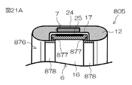
21A and 21B are cross-sectional views of the outer peripheral portion of the
第8実施形態に係る推進ユニット805は、第1実施形態に係る推進ユニット5と同様の構成を備えている。すなわち、推進ユニット805は、第1実施形態に係る推進ユニット5の構成に加えて、ダクト12の内周面とリム16の外周面との間への異物の進入を防止する防塵構造876を備えている。防塵構造876は、図21Aに示すシール877を含む構成であってもよいし、図21Bに示す防塵リング879を含む構成であってもよい。
The
具体的には、図21Aに示す防塵構造876は、前後方向に間隔を空けて配置された二対のシール877および固定リング878を含む。シール877は、全周に亘って連続した環状である。前側のシール877は、リム16の前端部に配置されており、後側のシール877は、リム16の後端部に配置されている。シール877は、全周に亘ってリム16に接している。シール877は、対の固定リング878を取り囲んでいる。シール877は、対の固定リング878に保持されている。シール877は、固定リング878によってリム16に押し付けられている。これにより、シール877がリム16に密着している。固定リング878は、シール877の内側からダクト12の内側に延びている。固定リング878は、ダクト12に固定されている。したがって、シール877は、対の固定リング878を介してダクト12に固定されている。リム16がダクト12に対してプロペラ軸線A2まわりに回転すると、リム16およびシール877は、シール877がリム16に密着した状態で、プロペラ軸線A2まわりに相対回転する。
Specifically, the dust-
ダクト12の内周面とリム16の外周面との間の空間には、潤滑剤が充填されている。前側の対のシール877および固定リング878は、リム16の前端部とダクト12との間の軸方向への隙間を塞いでおり、後側の対のシール877および固定リング878は、リム16の後端部とダクト12との間の軸方向への隙間を塞いでいる。したがって、ダクト12の内周面とリム16の外周面との間の空間は、防塵構造876によって密閉されている。そのため、ダクト12とリム16との間から潤滑剤が漏れることが防止される。さらに、小石や水などの異物が、ダクト12とリム16との間に進入することが防止される。
A space between the inner peripheral surface of the
一方、図21Bに示す防塵構造876は、前後方向に間隔を空けて配置された2つの防塵リング879を含む。防塵リング879は、ダクト12に固定されている。前側の防塵リング879は、ダクト12の前端部の内側から後方に延びている。前側の防塵リング879の後端部とダクト12の前端部との間には、軸方向への隙間G1が設けられている。同様に、後側の防塵リング879は、ダクト12の後端部の内側から前方に延びている。後側の防塵リング879の前端部とダクト12の後端部との間には、軸方向への隙間G1が設けられている。
On the other hand, the dust-
図21Bに示すように、前側の防塵リング879は、後端部から前方に延びる複数のスリット880を含む。同様に、後側の防塵リング879は、前端部から後方に延びる複数のスリット880を含む。複数のスリット880は、周方向に等間隔で配列されている。図22に示すように、スリット880は、周方向に対向する2つの傾斜面881の間に設けられている。スリット880は、ダクト12の内周面とリム16の外周面との間の空間に通じている。防塵リング879の最小隙間G2(スリット880の最小幅)は、防塵リング879とリム16との間の軸方向への最小隙間G1より狭い。さらに、防塵リング879とリム16との間の軸方向への最小隙間G1は、ダクト12とリム16との間の最小隙間G3より狭い。
As shown in FIG. 21B, the front dust-
ダクト12内に進入した水は、一方の防塵リング879とリム16との間の隙間G1や、一方の防塵リング879の隙間G2を通過して、ダクト12の内周面とリム16の外周面との間の空間に流入する。そして、この水は、他方の防塵リング879とリム16との間の隙間G1や、他方の防塵リング879の隙間G2を通過して、ダクト12の内周面とリム16の外周面との間の空間から流出する。隙間G1および隙間G2より大きな異物は、防塵リング879およびリム16によって、ダクト12の内周面とリム16の外周面との間の空間への進入が防止される。さらに、隙間G1および隙間G2が、ダクト12とリム16との間の隙間G3より狭いので、隙間G3より大きな異物が、ダクト12とリム16との間に進入して、リム16の回転が阻害されることを防止できる。しかも、水が、ダクト12とリム16との間を流れるので、ダクト12とリム16との間に存在する微小な異物を水流によって排出できる。
The water that has entered the
[第9実施形態]
次に、この発明の第9実施形態について説明する。
この第9実施形態と前述の第1実施形態との主要な相違点は、光を発する発光体が、プロペラに配置されていることである。
図23は、この発明の第9実施形態に係る推進ユニット905の背面図である。図24Aおよび図24Bは、この発明の第9実施形態に係る推進ユニット905の一部の断面図である。図23〜図24Bにおいて、前述の図1〜図22に示された各部と同等の構成部分については、図1等と同一の参照符号を付してその説明を省略する。
[Ninth Embodiment]
Next, a ninth embodiment of the invention will be described.
The main difference between the ninth embodiment and the first embodiment described above is that a light emitter that emits light is disposed on a propeller.
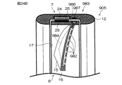
FIG. 23 is a rear view of the
第9実施形態に係る推進ユニット905は、第1実施形態に係る推進ユニット5と同様の構成を備えている。すなわち、推進ユニット905は、第1実施形態に係る推進ユニット5の構成に加えて、光を発する複数の発光体982と、電力を発生する発電装置983と、発電装置983から発光体982に電力を供給する複数の基板984(フレキシブルプリント基板)とを含む。発光体982は、電灯であってもよいし、LED(発光体ダイオード)であってもよい。図23に示すように、各羽根15は、複数の発光体982を保持している。共通の羽根15に保持されている複数の発光体982は、径方向に延びる直線状の列を構成している。
The
図24Aおよび図24Bに示すように、発光体982は、羽根15に埋め込まれており、その一部が、羽根15の背面から露出している。複数の基板984は、それぞれ、複数の羽根15に埋め込まれている。基板984は、共通の羽根15に保持されている複数の発光体982に電気的に接続されている。さらに、基板984は、発電装置983に電気的に接続されている。発光体982に供給される電力を制御する電気回路は、基板984に実装されている。基板984は、発電装置983から発光体982に電力を供給することにより、発光体982を発光させる。発電装置983は、図24Aに示す発電用コイル985を含む構成であってもよいし、図24Bに示す発電用コイル986および発電用マグネット987を含む構成であってもよい。
As shown in FIGS. 24A and 24B, the
具体的には、図24Aに示す発電装置983は、リム16に取り付けられた複数の発電用コイル985を含む。発電用コイル985は、ステータ24に対向する位置でリム16に取り付けられている。発電用コイル985は、リム16と共にプロペラ軸線A2まわりに回転する。電動モータ7がプロペラ6を回転させると、ステータ24および発電用コイル985が相対回転し、発電用コイル985を通過する磁束が変化する。そのため、発電用コイル985に電流(誘導電流)が発生する。したがって、電動モータ7がプロペラ6を回転させると、発光体982が発光する。
Specifically, the
基板984は、発電用コイル985で発生する電流値に応じて発光体982の発光状態を変化させる。発電用コイル985で発生する電流は、プロペラ6の回転速度に応じて変化する。さらに、プロペラ6の回転速度が同じであっても、高トルクでプロペラ6を回転させる場合には、ステータ24に供給される電力が低トルクの場合よりも大きいので、発電用コイル985で発生する電流が増加する。したがって、発光体982の発光状態は、回転速度およびトルクを含むプロペラ6の回転状態に応じて変化する。
The
一方、図24Bに示す発電装置983は、リム16に取り付けられた複数の発電用コイル986と、ダクト12に取り付けられた複数の発電用マグネット987とを含む。発電用コイル986および発電用マグネット987は、径方向に対向している。発電用コイル986は、リム16と共にプロペラ軸線A2まわりに回転する。電動モータ7がプロペラ6を回転させると、発電用コイル986および発電用マグネット987が相対回転し、発電用コイル986を通過する磁束が変化する。そのため、発電用コイル986に電流が発生する。したがって、電動モータ7がプロペラ6を回転させると、発光体982が発光する。発光体982の発光状態は、プロペラ6の回転状態に応じて変化する。
On the other hand, the
[第10実施形態]
次に、この発明の第10実施形態について説明する。
この第10実施形態と前述の第2実施形態との主要な相違点は、光を発する発光体が、ダクトおよび固定羽根に配置されていることである。
図25は、この発明の第10実施形態に係る推進ユニット1005の背面図である。図26Aおよび図26Bは、この発明の第10実施形態に係る推進ユニット1005の外周部の断面図である。図25〜図26Bにおいて、前述の図1〜図24Bに示された各部と同等の構成部分については、図1等と同一の参照符号を付してその説明を省略する。
[Tenth embodiment]
Next, a tenth embodiment of the invention is described.
The main difference between the tenth embodiment and the second embodiment described above is that a light emitter that emits light is disposed in a duct and a fixed blade.
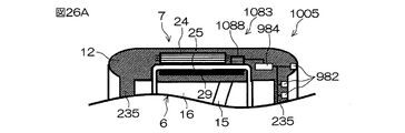
FIG. 25 is a rear view of the
第10実施形態に係る推進ユニット1005は、第2実施形態に係る推進ユニット205と同様の構成を備えている。すなわち、推進ユニット1005は、第2実施形態に係る推進ユニット205の構成に加えて、光を発する複数の発光体982と、電力を発生する発電装置1083と、発電装置1083から発光体982に電力を供給する複数の基板984とを含む。図25に示すように、ダクト12および固定羽根235は、複数の発光体982を保持している。ダクト12に保持されている複数の発光体982は、ダクト12の背面に沿って環状に配置されている。固定羽根235に保持されている複数の発光体982は、径方向に延びる直線状の列を構成している。
The
図26Aおよび図26Bに示すように、発光体982は、ダクト12および固定羽根235に埋め込まれており、その一部が、ダクト12および固定羽根235の背面から露出している。複数の基板984は、ダクト12および固定羽根235に埋め込まれている。基板984は、複数の発光体982に電気的に接続されている。さらに、基板984は、発電装置1083に電気的に接続されている。基板984は、発電装置1083から発光体982に電力を供給することにより、発光体982を発光させる。発電装置1083は、図26Aに示す発電用コイル1088を含む構成であってもよいし、図26Bに示す発電用コイル1089および発電用マグネット1090を含む構成であってもよい。
As shown in FIGS. 26A and 26B, the
具体的には、図26Aに示す発電装置1083は、ダクト12に取り付けられた複数の発電用コイル1088を含む。発電用コイル1088は、ロータ25のマグネット29に対向する位置でダクト12に取り付けられている。電動モータ7がプロペラ6を回転させると、マグネット29および発電用コイル1088が相対回転し、発電用コイル1088を通過する磁束が変化する。そのため、発電用コイル1088に電流が発生する。したがって、電動モータ7がプロペラ6を回転させると、発光体982が発光する。発光体982の発光状態は、プロペラ6の回転状態に応じて変化する。
Specifically, the
一方、図26Bに示す発電装置1083は、ダクト12に取り付けられた複数の発電用コイル1089と、リム16に取り付けられた複数の発電用マグネット1090とを含む。発電用コイル1089および発電用マグネット1090は、径方向に対向している。発電用マグネット1090は、リム16と共にプロペラ軸線A2まわりに回転する。電動モータ7がプロペラ6を回転させると、発電用コイル1089および発電用マグネット1090が相対回転し、発電用コイル1089を通過する磁束が変化する。そのため、発電用コイル1089に電流が発生する。したがって、電動モータ7がプロペラ6を回転させると、発光体982が発光する。発光体982の発光状態は、プロペラ6の回転状態に応じて変化する。
On the other hand, the
[他の実施形態]
この発明の第1〜第10実施形態の説明は以上であるが、この発明は、前述の第1〜第10実施形態の内容に限定されるものではなく、請求項記載の範囲内において種々の変更が可能である。
たとえば、前述の第1〜第10実施形態では、電動モータが、ラジアル方向に対向するステータおよびロータを含むラジアルギャップモータである場合について説明した。しかし、電動モータは、アキシャル方向に対向するステータおよびロータを含むアキシャルギャップモータであってもよい。
[Other Embodiments]
Although the description of the first to tenth embodiments of the present invention has been described above, the present invention is not limited to the contents of the first to tenth embodiments described above, and various modifications can be made within the scope of the claims. It can be changed.
For example, in the above-described first to tenth embodiments, the case where the electric motor is a radial gap motor including a stator and a rotor facing in the radial direction has been described. However, the electric motor may be an axial gap motor including a stator and a rotor facing in the axial direction.
また、前述の第1〜第10実施形態のうちの少なくとも2つの構成が組み合わされてもよい。たとえば、前述の第3実施形態では、プロペラの中心部に回転軸が設けられていない場合について説明した。しかし、第2実施形態に係るプロペラの回転軸が、第3実施形態に係るプロペラの中心部に設けられていてもよい。すなわち、第2実施形態に係る構成と、第3実施形態に係る構成とが組み合わされてもよい。また、前述の第3〜8実施形態では、発光体が設けられていない場合について説明した。しかし、第9および第10実施形態に係る発光体が、第3〜8実施形態に係る推進ユニットに設けられていてもよい。 Further, at least two configurations of the first to tenth embodiments described above may be combined. For example, in the above-described third embodiment, the case where the rotation shaft is not provided at the center of the propeller has been described. However, the rotating shaft of the propeller according to the second embodiment may be provided at the center of the propeller according to the third embodiment. That is, the configuration according to the second embodiment and the configuration according to the third embodiment may be combined. In the above-described third to eighth embodiments, the case where the light emitter is not provided has been described. However, the light emitters according to the ninth and tenth embodiments may be provided in the propulsion unit according to the third to eighth embodiments.
また、前述の第1〜第10実施形態では、モータECUが、モータ回転角検出装置の検出値に基づいて電動モータの回転角(ロータの位置)を検出する場合について説明した。しかし、モータECUは、電動モータの誘起電圧から電動モータの回転角を検出してもよい。すなわち、電動モータの誘起電圧から電動モータの回転角を検出するモータ回転角検出部が、モータECUに設けられていてもよい。この場合、モータ回転角検出装置は設けられていなくてもよい。 In the first to tenth embodiments described above, the case where the motor ECU detects the rotation angle (rotor position) of the electric motor based on the detection value of the motor rotation angle detection device has been described. However, the motor ECU may detect the rotation angle of the electric motor from the induced voltage of the electric motor. That is, the motor ECU may be provided with a motor rotation angle detector that detects the rotation angle of the electric motor from the induced voltage of the electric motor. In this case, the motor rotation angle detection device may not be provided.
また、前述の第1〜第10実施形態では、ステアリングシャフトおよびダクトが、ブラケットに対してステアリング軸線まわりに回転する場合について説明した。しかし、ダクトだけがブラケットに対してステアリング軸線まわりに回転してもよい。すなわち、ステアリングシャフトが、ブラケットに固定されており、ダクトが、ステアリングシャフトに対してステアリング軸線まわりに回転可能にステアリングシャフトに連結されていてもよい。 In the first to tenth embodiments, the case where the steering shaft and the duct rotate around the steering axis with respect to the bracket has been described. However, only the duct may rotate about the steering axis relative to the bracket. That is, the steering shaft may be fixed to the bracket, and the duct may be connected to the steering shaft so as to be rotatable around the steering axis with respect to the steering shaft.
また、前述の第10実施形態では、プロペラの回転に伴って電力を発生する発電装置からの電力が、発光体に供給される場合について説明した。しかし、第10実施形態のように、発光体が、固定部分(ダクト)に配置されている場合、発電装置が設けられていなくてもよい。すなわち、電動モータに電力を供給するモータ電力源(バッテリー)からの電力が発光体に供給されてもよい。この場合、モータECUが、発光体への電力供給を制御することにより、発光体の発光状態を制御してもよい。 Further, in the above-described tenth embodiment, the case has been described in which the power from the power generation device that generates power with the rotation of the propeller is supplied to the light emitter. However, as in the tenth embodiment, when the light emitter is disposed in the fixed portion (duct), the power generation device may not be provided. That is, power from a motor power source (battery) that supplies power to the electric motor may be supplied to the light emitter. In this case, the motor ECU may control the light emission state of the light emitter by controlling the power supply to the light emitter.
その他、特許請求の範囲に記載された事項の範囲で種々の設計変更を施すことが可能である。
以下に、特許請求の範囲に記載された構成要素と前述の実施形態における構成要素との対応関係を示す。
船舶:船舶V1
ブラケット:ブラケット2
ステアリング軸線:ステアリング軸線A1
ステアリングシャフト:ステアリングシャフト4
ダクト:ダクト12
プロペラ軸線:プロペラ軸線A2
羽根:羽根15
リム:リム16
プロペラ:プロペラ6、206、406、606、706
電動モータ:電動モータ7、307、407
船舶推進装置:船舶推進装置1
ステータ:ステータ24
ロータ:ロータ25
マグネット:マグネット29
駆動ギヤ:駆動ギヤ342
従動ギヤ:従動ギヤ343
歯車伝達機構:歯車伝達機構341
前側プロペラ:前側プロペラ444
後側プロペラ:後側プロペラ445
前側羽根:前側羽根446
前側リム:前側リム447
後側羽根:後側羽根448
後側リム:後側リム449
前側電動モータ:前側電動モータ452
後側電動モータ:後側電動モータ453
前側ステータ:前側ステータ454
前側ロータ:前側ロータ455
後側ステータ:後側ステータ456
後側ロータ:後側ロータ457
前側従動ギヤ:前側従動ギヤ558
後側従動ギヤ:後側従動ギヤ559
歯車伝達機構:歯車伝達機構541
制御装置:モータECU13
回転量規制部:外周側規制部660、760、中心側規制部770
被支持部:前側被支持部661
長孔:前側挿入孔665
支持部:前側支持部662
前側回転軸:前側回転軸767
後側回転軸:後側回転軸768
前側噛み合い部:前側噛み合い部771
後側噛み合い部:後側噛み合い部772
発光体:発光体982
発電用コイル:発電用コイル985、986、1088、1089
発電用マグネット:発電用マグネット987、1090
In addition, various design changes can be made within the scope of matters described in the claims.
The correspondence between the constituent elements described in the claims and the constituent elements in the above-described embodiment will be shown below.
Ship: Ship V1
Bracket:
Steering axis: Steering axis A1
Steering shaft:
Duct:
Propeller axis: Propeller axis A2
Feather:
Rim:
Propeller:
Electric motor:
Ship propulsion device:
Stator:
Rotor:
Magnet:
Drive gear:
Driven gear: driven
Gear transmission mechanism:
Front propeller:
Rear propeller:
Front blade:
Front rim:
Rear blade:
Rear rim:
Front electric motor: Front
Rear electric motor: rear
Front stator:
Front rotor:
Rear stator:
Rear rotor:
Front driven gear: Front driven
Rear driven gear: rear driven
Gear transmission mechanism:
Control device:
Rotation amount regulation part: outer circumference
Supported part: front supported
Long hole:
Support part:
Front rotary shaft: Front
Rear rotating shaft:
Front meshing portion:
Rear meshing portion:
Light emitter:
Power generation coil:
Magnet for power generation: Magnets for
1 船舶推進装置
2 ブラケット
4 ステアリングシャフト
6 プロペラ
7 電動モータ
12 ダクト
13 モータECU
15 羽根
16 リム
24 ステータ
25 ロータ
29 マグネット
206 プロペラ
307 電動モータ
341 歯車伝達機構
342 駆動ギヤ
343 従動ギヤ
406 プロペラ
407 電動モータ
444 前側プロペラ
445 後側プロペラ
446 前側羽根
447 前側リム
448 後側羽根
449 後側リム
452 前側電動モータ
453 後側電動モータ
454 前側ステータ
455 前側ロータ
456 後側ステータ
457 後側ロータ
541 歯車伝達機構
558 前側従動ギヤ
559 後側従動ギヤ
606 プロペラ
660 外周側規制部
661 前側被支持部
662 前側支持部
665 前側挿入孔
706 プロペラ
760 外周側規制部
767 前側回転軸
768 後側回転軸
770 中心側規制部
771 前側噛み合い部
772 後側噛み合い部
982 発光体
985 発電用コイル
986 発電用コイル
987 発電用マグネット
1088 発電用コイル
1089 発電用コイル
1090 発電用マグネット
A1 ステアリング軸線
A2 プロペラ軸線
V1 船舶
DESCRIPTION OF
15
Claims (18)
略鉛直なステアリング軸線まわりに前記ブラケットに対して回転可能なダクトと、
複数の羽根と、前記複数の羽根を取り囲む筒状のリムとを含み、前記ダクトによって取り囲まれており、水平方向に延びるプロペラ軸線まわりに前記ダクトに対して回転可能なプロペラと、
前記ダクトに対して前記リムを回転させることにより、前記プロペラを回転させる電動モータとを含む、船舶推進装置。 A bracket attachable to the stern of the ship,
A duct rotatable relative to the bracket about a substantially vertical steering axis;
A propeller that includes a plurality of blades and a cylindrical rim that surrounds the plurality of blades, is surrounded by the duct, and is rotatable with respect to the duct about a propeller axis extending in a horizontal direction;
A marine vessel propulsion apparatus comprising: an electric motor that rotates the propeller by rotating the rim with respect to the duct.
前記前側プロペラは、複数の前側羽根と、前記複数の前側羽根を取り囲む筒状の前側リムとを含み、
前記後側プロペラは、複数の後側羽根と、前記複数の後側羽根を取り囲む筒状の後側リムとを含む、請求項1に記載の船舶推進装置。 The propellers are arranged in a direction along the propeller axis, and include a front propeller and a rear propeller that are rotationally driven in opposite directions by the electric motor,
The front propeller includes a plurality of front blades and a cylindrical front rim that surrounds the plurality of front blades,
The marine vessel propulsion device according to claim 1, wherein the rear propeller includes a plurality of rear blades and a cylindrical rear rim that surrounds the plurality of rear blades.
前記前側電動モータは、前記ダクトの少なくとも一部によって構成された前側ステータと、前記前側リムの少なくとも一部によって構成された前側ロータとを含み、
前記後側電動モータは、前記ダクトの少なくとも一部によって構成された後側ステータと、前記後側リムの少なくとも一部によって構成された後側ロータとを含む、請求項6に記載の船舶推進装置。 The electric motor rotates the front rim relative to the duct to rotate the front propeller, and rotates the rear rim relative to the duct to rotate the rear propeller. A rear electric motor that rotates,
The front electric motor includes a front stator constituted by at least a part of the duct, and a front rotor constituted by at least a part of the front rim,
The marine vessel propulsion device according to claim 6, wherein the rear electric motor includes a rear stator constituted by at least a part of the duct and a rear rotor constituted by at least a part of the rear rim. .
前記電動モータは、前記前側リムを前記プロペラ軸線まわりに回転させる前側電動モータと、前記後側リムを前記プロペラ軸線まわりに回転させる後側電動モータとを含み、前記前側リムおよび後側リムを前記プロペラ軸線まわりに相対回転させることにより、前記プロペラのピッチを変更する、請求項1に記載の船舶推進装置。 The rim includes a front rim and a rear rim that support the blade such that an inclination angle of the blade with respect to the propeller axis changes with relative rotation around the propeller axis,
The electric motor includes a front electric motor that rotates the front rim around the propeller axis, and a rear electric motor that rotates the rear rim around the propeller axis, and the front rim and the rear rim are The marine vessel propulsion apparatus according to claim 1, wherein the propeller pitch is changed by relative rotation about a propeller axis.
前記回転量規制部は、前記前側回転軸および後側回転軸にそれぞれ設けられており、所定の角度範囲内で前記プロペラ軸線まわりに相対回転可能に噛み合う前側噛み合い部および後側噛み合い部を含む、請求項11または12に記載の船舶推進装置。 The propeller extends along the propeller axis, extends along the propeller axis together with the front rim, extends along the propeller axis, and around the propeller axis together with the rear rim. And a rear rotating shaft that rotates,
The rotation amount restricting portion is provided on each of the front rotation shaft and the rear rotation shaft, and includes a front meshing portion and a rear meshing portion that mesh with each other so as to be relatively rotatable around the propeller axis within a predetermined angle range. The ship propulsion device according to claim 11 or 12.
前記ダクトは、前記ステアリングシャフトの下部に取り付けられており、前記ステアリングシャフトと共に前記ステアリング軸線まわりに回転可能である、請求項1〜13のいずれか一項に記載の船舶推進装置。 A steering shaft extending along the steering axis and rotatable about the steering axis relative to the bracket;
The marine vessel propulsion device according to any one of claims 1 to 13, wherein the duct is attached to a lower portion of the steering shaft and is rotatable around the steering axis along with the steering shaft.
前記船舶推進装置は、少なくとも一部が前記ステータに対向する位置で前記リムに取り付けられており、前記リムと共に前記プロペラ軸線まわりに回転する発電用コイルをさらに含み、
前記発光体は、前記発電用コイルに接続されており、前記プロペラに配置されている、請求項15または16に記載の船舶推進装置。 The electric motor includes a stator constituted by at least a part of the duct, and a rotor constituted by at least a part of the rim,
The marine vessel propulsion device further includes a power generation coil that is attached to the rim at a position at least partially facing the stator, and that rotates about the propeller axis together with the rim.
The marine vessel propulsion device according to claim 15 or 16, wherein the light emitter is connected to the power generation coil and disposed on the propeller.
前記ダクトに取り付けられており、前記発電用コイルに対向する発電用マグネットとをさらに含み、
前記発光体は、前記発電用コイルに接続されており、前記プロペラに配置されている、請求項15または16に記載の船舶推進装置。 A power generating coil attached to the rim and rotating about the propeller axis together with the rim;
A power generation magnet attached to the duct and facing the power generation coil;
The marine vessel propulsion device according to claim 15 or 16, wherein the light emitter is connected to the power generation coil and disposed on the propeller.
Priority Applications (4)
| Application Number | Priority Date | Filing Date | Title |
|---|---|---|---|
| JP2011244661A JP5872255B2 (en) | 2011-11-08 | 2011-11-08 | Ship propulsion device |
| EP12190355.3A EP2591993B1 (en) | 2011-11-08 | 2012-10-29 | Marine vessel propulsion device |
| CN201210439459.2A CN103085959B (en) | 2011-11-08 | 2012-10-30 | Marine propulsion |
| US13/670,610 US8956195B2 (en) | 2011-11-08 | 2012-11-07 | Marine vessel propulsion device |
Applications Claiming Priority (1)
| Application Number | Priority Date | Filing Date | Title |
|---|---|---|---|
| JP2011244661A JP5872255B2 (en) | 2011-11-08 | 2011-11-08 | Ship propulsion device |
Publications (2)
| Publication Number | Publication Date |
|---|---|
| JP2013100013A true JP2013100013A (en) | 2013-05-23 |
| JP5872255B2 JP5872255B2 (en) | 2016-03-01 |
Family
ID=47143598
Family Applications (1)
| Application Number | Title | Priority Date | Filing Date |
|---|---|---|---|
| JP2011244661A Active JP5872255B2 (en) | 2011-11-08 | 2011-11-08 | Ship propulsion device |
Country Status (4)
| Country | Link |
|---|---|
| US (1) | US8956195B2 (en) |
| EP (1) | EP2591993B1 (en) |
| JP (1) | JP5872255B2 (en) |
| CN (1) | CN103085959B (en) |
Cited By (24)
| Publication number | Priority date | Publication date | Assignee | Title |
|---|---|---|---|---|
| KR101523913B1 (en) * | 2013-09-25 | 2015-05-29 | 삼성중공업 주식회사 | Propulsion apparatus for vessel |
| JP2015214898A (en) * | 2014-05-08 | 2015-12-03 | ナカシマプロペラ株式会社 | Power generation device |
| EP3000718A1 (en) | 2014-09-26 | 2016-03-30 | Yamaha Hatsudoki Kabushiki Kaisha | Outboard motor provided with an electrical propulsion device |
| EP3037341A1 (en) | 2014-12-24 | 2016-06-29 | Yamaha Hatsudoki Kabushiki Kaisha | Rotating electrical machine apparatus and boat body with rotating electrical machine apparatus |
| JP2016531784A (en) * | 2013-09-24 | 2016-10-13 | ロールス − ロイス マーリン エーエス | Modular azimuth thruster |
| WO2017082248A1 (en) * | 2015-11-11 | 2017-05-18 | ヤマハ発動機株式会社 | Ship propulsion device |
| JP2017525613A (en) * | 2014-08-22 | 2017-09-07 | ロールスロイス マリン アクティーゼルスカブ | Ship with propulsion device |
| CN107786032A (en) * | 2017-11-03 | 2018-03-09 | 合肥倍豪海洋装备技术有限公司 | A kind of magnetic bearing device applied to ship Shaftless propeller |
| US10167067B2 (en) | 2016-11-14 | 2019-01-01 | Yamaha Hatsudoki Kabushiki Kaisha | Vessel propulsion apparatus and vessel including the same |
| US10435127B2 (en) | 2016-11-14 | 2019-10-08 | Yamaha Hatsudoki Kabushiki Kaisha | Vessel propulsion system and vessel including the same |
| KR20220082321A (en) * | 2020-12-10 | 2022-06-17 | 강현욱 | Life Boat Using Water Jet Module |
| DE102022101872A1 (en) | 2021-02-25 | 2022-08-25 | Brunswick Corporation | Marine propulsion device and method of manufacturing a marine propulsion device with impact protection |
| EP4067220A1 (en) | 2021-03-30 | 2022-10-05 | Mitsubishi Heavy Industries, Ltd. | Propulsor for marine vessel, and marine vessel |
| DE102022205599A1 (en) | 2021-06-24 | 2022-12-29 | Mitsubishi Heavy Industries, Ltd. | fluid machine |
| JP7199585B1 (en) | 2022-05-10 | 2023-01-05 | 勉 桐山 | ocean current trimaran |
| DE102022115286A1 (en) | 2021-07-15 | 2023-01-19 | Brunswick Corporation | DEVICES AND METHOD FOR THE MANUFACTURE OF DEVICES FOR MOUNTING A PROPULSOR ON A VESSEL |
| US11572146B2 (en) | 2021-02-25 | 2023-02-07 | Brunswick Corporation | Stowable marine propulsion systems |
| US11591057B2 (en) | 2021-02-25 | 2023-02-28 | Brunswick Corporation | Propulsion devices and methods of making propulsion devices that align propeller blades for marine vessels |
| USD983838S1 (en) | 2021-06-14 | 2023-04-18 | Brunswick Corporation | Cowling for an outboard motor |
| US11801926B2 (en) | 2021-02-25 | 2023-10-31 | Brunswick Corporation | Devices and methods for making devices for supporting a propulsor on a marine vessel |
| US11851150B2 (en) | 2021-02-25 | 2023-12-26 | Brunswick Corporation | Propulsion devices with lock devices and methods of making propulsion devices with lock devices for marine vessels |
| US11873071B2 (en) | 2021-02-25 | 2024-01-16 | Brunswick Corporation | Stowable propulsion devices for marine vessels and methods for making stowable propulsion devices for marine vessels |
| US11939036B2 (en) | 2021-07-15 | 2024-03-26 | Brunswick Corporation | Devices and methods for coupling propulsion devices to marine vessels |
| USD1023888S1 (en) | 2022-01-14 | 2024-04-23 | Brunswick Corporation | Cowling on a deployable thruster for a marine vessel |
Families Citing this family (29)
| Publication number | Priority date | Publication date | Assignee | Title |
|---|---|---|---|---|
| JP5844617B2 (en) * | 2011-11-08 | 2016-01-20 | ヤマハ発動機株式会社 | Ship propulsion device |
| US8976043B2 (en) * | 2012-08-20 | 2015-03-10 | Textron Innovations, Inc. | Illuminated sidestick controller, such as an illuminated sidestick controller for use in aircraft |
| ITTO20130045A1 (en) * | 2013-01-18 | 2014-07-19 | P Gevs Srl | OUTBOARD PROPULSION SYSTEM FOR VESSELS |
| CN103818537A (en) * | 2013-10-23 | 2014-05-28 | 李继东 | Aircraft carrier, large ship, submarine and tail-rudder-free super-power turbine assembly |
| CN104210635B (en) * | 2014-09-15 | 2016-08-24 | 沈路平 | A kind of electromagnetic power propeller group, propeller and structure thereof |
| FR3029499B1 (en) * | 2014-12-08 | 2018-04-13 | Hy-Generation | CIRCUMFERENTIAL DRIVE PROPELLER AND SELF-PROPELLED BLADES |
| CN105035293A (en) * | 2015-07-24 | 2015-11-11 | 苏州金业船用机械厂 | Guide-tube type double-flow-direction propeller |
| US20170030368A1 (en) * | 2015-07-29 | 2017-02-02 | John McIntyre | Monoblock axial pump |
| WO2017060341A1 (en) * | 2015-10-09 | 2017-04-13 | Hochschule Flensburg | Position changing device, in particular for a watercraft |
| DE102015219657A1 (en) * | 2015-10-09 | 2017-04-13 | Hochschule Flensburg | Drive device, in particular for a watercraft |
| DE102016204304A1 (en) * | 2016-03-16 | 2017-09-21 | Voith Patent Gmbh | Jet propulsion in particular for a watercraft and method for retrofitting a jet propulsion system |
| JP2018079742A (en) | 2016-11-14 | 2018-05-24 | ヤマハ発動機株式会社 | Ship propulsion unit and ship with the same |
| CN106672186B (en) * | 2017-02-09 | 2018-07-06 | 中国科学院电工研究所 | A kind of full open model binary is to turning underwater propulsion system |
| US10384754B2 (en) * | 2017-11-14 | 2019-08-20 | Sangha Cho | Azimuth thruster system driven by cooperating prime movers and control method |
| CN108791791A (en) * | 2018-06-11 | 2018-11-13 | 陈杰明 | A kind of remote control electric machine outside propeller |
| CN109178268B (en) * | 2018-09-13 | 2021-02-26 | 上海船舶研究设计院(中国船舶工业集团公司第六0四研究院) | External drive type marine propulsion system |
| CN109378910A (en) * | 2018-10-23 | 2019-02-22 | 中船天力(天津)科技股份有限公司 | Magnetcisuspension suspension propeller |
| CN109501988A (en) * | 2018-12-12 | 2019-03-22 | 方晓毅 | The shaftless co-axial contra rotating propeller of magnetic suspension wheel rim drive-type |
| FR3092822B1 (en) * | 2019-02-18 | 2022-06-10 | Safran | Electric thruster for aircraft and method of using such a thruster |
| CN111102148A (en) * | 2019-12-24 | 2020-05-05 | 青岛度丘新能源技术有限公司 | Rotary motion subsidiary power generation device and application thereof |
| JP2021104715A (en) * | 2019-12-26 | 2021-07-26 | ヤマハ発動機株式会社 | Ship propulsion device and ship |
| JP2021104714A (en) | 2019-12-26 | 2021-07-26 | ヤマハ発動機株式会社 | Ship propulsion device and ship |
| DE102020107038A1 (en) * | 2020-03-13 | 2021-09-16 | Torqeedo Gmbh | Method and device for adjusting the flow properties of a propeller |
| JP2022018646A (en) * | 2020-07-16 | 2022-01-27 | ヤマハ発動機株式会社 | Outboard motor |
| CN112498643B (en) * | 2020-12-15 | 2021-09-28 | 上海瀚星船舶科技有限公司 | Marine retractable air hub propulsion device |
| CN112498644B (en) * | 2020-12-15 | 2021-12-03 | 上海瀚星船舶科技有限公司 | Inland river ship electric propulsion system and inland river ship navigation control method comprising same |
| CN112910173B (en) * | 2021-01-29 | 2022-08-02 | 广船国际有限公司 | Power generation facility and boats and ships for boats and ships |
| CN113949178A (en) * | 2021-09-29 | 2022-01-18 | 西安交通大学 | Coaxial double-paddle rotor salient pole motor propulsion power system structure |
| CN114735176B (en) * | 2022-04-15 | 2023-05-02 | 武汉理工大学 | Shaftless propeller and control method thereof |
Citations (20)
| Publication number | Priority date | Publication date | Assignee | Title |
|---|---|---|---|---|
| DE1781332A1 (en) * | 1968-09-28 | 1970-12-03 | Carl Liebau | Propulsion device for ships |
| US3914629A (en) * | 1974-12-13 | 1975-10-21 | William P Gardiner | Centerless brushless DC motor |
| JPS5992297A (en) * | 1982-11-18 | 1984-05-28 | Mitsubishi Heavy Ind Ltd | Dual inverting nozzle propeller |
| JPS59179293U (en) * | 1983-05-18 | 1984-11-30 | 石川島播磨重工業株式会社 | propeller device |
| DE3912910A1 (en) * | 1989-04-20 | 1990-10-25 | Gabriel Reinhard | Jet-propulsion unit for boat or aircraft - comprises rotary jet pipe with internal auger or blades forming driving members |
| JPH0429492U (en) * | 1990-07-04 | 1992-03-10 | ||
| US5185545A (en) * | 1990-08-23 | 1993-02-09 | Westinghouse Electric Corp. | Dual propeller shock resistant submersible propulsor unit |
| US5289068A (en) * | 1990-08-23 | 1994-02-22 | Westinghouse Electric Corp. | Two-stage submersible propulsor unit for water vehicles |
| JPH1047371A (en) * | 1996-08-02 | 1998-02-17 | Exedy Corp | Damper disk assembly unit |
| JPH11128588A (en) * | 1997-10-30 | 1999-05-18 | Mitsubishi Electric Corp | Motor for washing use |
| JPH11245889A (en) * | 1998-01-08 | 1999-09-14 | Electric Boat Corp | Variable pitch propeller device |
| JP2002081366A (en) * | 2000-05-10 | 2002-03-22 | Oriental Trade:Kk | Power generating and light emitting device utilizing wind force |
| US6416368B1 (en) * | 2000-03-31 | 2002-07-09 | Bombardier Motor Corporation Of America | Unitary inboard electric marine propulsion system |
| FR2829101A1 (en) * | 2001-08-30 | 2003-03-07 | Marie Aude Viala | Outboard motor torque multiplier comprises casing supporting engine and screw free on shaft center serving as receptor pulley for engine torque transmitted by pulley and belt |
| JP2003214122A (en) * | 2001-11-14 | 2003-07-30 | Aisin Seiki Co Ltd | Valve opening/closing timing control device |
| KR100726291B1 (en) * | 2005-10-06 | 2007-06-11 | 삼성중공업 주식회사 | Silent and Anti-vibration underwater driving system |
| JP2007153240A (en) * | 2005-12-07 | 2007-06-21 | Honda Motor Co Ltd | Outboard motor |
| JP2007210549A (en) * | 2006-02-13 | 2007-08-23 | Honda Motor Co Ltd | Outboard motor |
| JP2008224007A (en) * | 2007-03-15 | 2008-09-25 | Aisin Aw Co Ltd | Spring damper |
| JP2009161003A (en) * | 2007-12-28 | 2009-07-23 | Kawasaki Heavy Ind Ltd | Thrust generating device |
Family Cites Families (12)
| Publication number | Priority date | Publication date | Assignee | Title |
|---|---|---|---|---|
| ATE115929T1 (en) * | 1990-02-06 | 1995-01-15 | Reinhard Gabriel | JET DRIVE FOR WATERCRAFT AND AIRCRAFT AND CIRCULATION PUMPS. |
| US5306183A (en) * | 1993-02-25 | 1994-04-26 | Harbor Branch Oceanographic Institute Inc. | Propulsion systems for submarine vessels |
| US5522335A (en) * | 1995-01-30 | 1996-06-04 | Westinghouse Electric Corporation | Combined azimuthing and tunnel auxillary thruster powered by integral and canned electric motor and marine vessel powered thereby |
| US7052341B2 (en) * | 2003-10-22 | 2006-05-30 | Yamaha Hatsudoki Kabushiki Kaisha | Method and apparatus for controlling a propulsive force of a marine vessel |
| DE10353566A1 (en) * | 2003-11-14 | 2005-06-23 | Reinhard Gabriel | jet propulsion |
| JP4337522B2 (en) | 2003-11-26 | 2009-09-30 | スズキ株式会社 | Electric outboard motor |
| EP1876094A3 (en) * | 2006-07-06 | 2008-03-19 | Neta N.V. | Retractable thruster for vessels |
| CN201082760Y (en) * | 2007-09-12 | 2008-07-09 | 汪素珍 | Propeller for ship |
| US8146369B2 (en) * | 2007-11-06 | 2012-04-03 | Borealis Technical Limited | Integrated direct drive starter/generator for turbines |
| JP5088959B2 (en) | 2008-03-28 | 2012-12-05 | ヤマハモーターエレクトロニクス株式会社 | Ship propulsion device |
| DE102009040471B4 (en) * | 2009-09-08 | 2016-07-21 | Tutech Innovation Gmbh | Mechanically propelled ship propulsor with high efficiency |
| US8299669B2 (en) * | 2010-10-18 | 2012-10-30 | Hamilton Sundstrand Corporation | Rim driven thruster having transverse flux motor |
-
2011
- 2011-11-08 JP JP2011244661A patent/JP5872255B2/en active Active
-
2012
- 2012-10-29 EP EP12190355.3A patent/EP2591993B1/en active Active
- 2012-10-30 CN CN201210439459.2A patent/CN103085959B/en active Active
- 2012-11-07 US US13/670,610 patent/US8956195B2/en active Active
Patent Citations (20)
| Publication number | Priority date | Publication date | Assignee | Title |
|---|---|---|---|---|
| DE1781332A1 (en) * | 1968-09-28 | 1970-12-03 | Carl Liebau | Propulsion device for ships |
| US3914629A (en) * | 1974-12-13 | 1975-10-21 | William P Gardiner | Centerless brushless DC motor |
| JPS5992297A (en) * | 1982-11-18 | 1984-05-28 | Mitsubishi Heavy Ind Ltd | Dual inverting nozzle propeller |
| JPS59179293U (en) * | 1983-05-18 | 1984-11-30 | 石川島播磨重工業株式会社 | propeller device |
| DE3912910A1 (en) * | 1989-04-20 | 1990-10-25 | Gabriel Reinhard | Jet-propulsion unit for boat or aircraft - comprises rotary jet pipe with internal auger or blades forming driving members |
| JPH0429492U (en) * | 1990-07-04 | 1992-03-10 | ||
| US5185545A (en) * | 1990-08-23 | 1993-02-09 | Westinghouse Electric Corp. | Dual propeller shock resistant submersible propulsor unit |
| US5289068A (en) * | 1990-08-23 | 1994-02-22 | Westinghouse Electric Corp. | Two-stage submersible propulsor unit for water vehicles |
| JPH1047371A (en) * | 1996-08-02 | 1998-02-17 | Exedy Corp | Damper disk assembly unit |
| JPH11128588A (en) * | 1997-10-30 | 1999-05-18 | Mitsubishi Electric Corp | Motor for washing use |
| JPH11245889A (en) * | 1998-01-08 | 1999-09-14 | Electric Boat Corp | Variable pitch propeller device |
| US6416368B1 (en) * | 2000-03-31 | 2002-07-09 | Bombardier Motor Corporation Of America | Unitary inboard electric marine propulsion system |
| JP2002081366A (en) * | 2000-05-10 | 2002-03-22 | Oriental Trade:Kk | Power generating and light emitting device utilizing wind force |
| FR2829101A1 (en) * | 2001-08-30 | 2003-03-07 | Marie Aude Viala | Outboard motor torque multiplier comprises casing supporting engine and screw free on shaft center serving as receptor pulley for engine torque transmitted by pulley and belt |
| JP2003214122A (en) * | 2001-11-14 | 2003-07-30 | Aisin Seiki Co Ltd | Valve opening/closing timing control device |
| KR100726291B1 (en) * | 2005-10-06 | 2007-06-11 | 삼성중공업 주식회사 | Silent and Anti-vibration underwater driving system |
| JP2007153240A (en) * | 2005-12-07 | 2007-06-21 | Honda Motor Co Ltd | Outboard motor |
| JP2007210549A (en) * | 2006-02-13 | 2007-08-23 | Honda Motor Co Ltd | Outboard motor |
| JP2008224007A (en) * | 2007-03-15 | 2008-09-25 | Aisin Aw Co Ltd | Spring damper |
| JP2009161003A (en) * | 2007-12-28 | 2009-07-23 | Kawasaki Heavy Ind Ltd | Thrust generating device |
Cited By (39)
| Publication number | Priority date | Publication date | Assignee | Title |
|---|---|---|---|---|
| US10618617B2 (en) | 2005-11-11 | 2020-04-14 | Yamaha Hatsudoki Kabushiki Kaisha | Marine propulsion unit |
| JP2016531784A (en) * | 2013-09-24 | 2016-10-13 | ロールス − ロイス マーリン エーエス | Modular azimuth thruster |
| US10549830B2 (en) | 2013-09-24 | 2020-02-04 | Kongsberg Maritime CM AS | Modular azimuth thruster |
| KR101523913B1 (en) * | 2013-09-25 | 2015-05-29 | 삼성중공업 주식회사 | Propulsion apparatus for vessel |
| JP2015214898A (en) * | 2014-05-08 | 2015-12-03 | ナカシマプロペラ株式会社 | Power generation device |
| JP2017525613A (en) * | 2014-08-22 | 2017-09-07 | ロールスロイス マリン アクティーゼルスカブ | Ship with propulsion device |
| US10202181B2 (en) | 2014-09-26 | 2019-02-12 | Yamaha Hatsudoki Kabushiki Kaisha | Electric propulsion device |
| EP3000718A1 (en) | 2014-09-26 | 2016-03-30 | Yamaha Hatsudoki Kabushiki Kaisha | Outboard motor provided with an electrical propulsion device |
| US10486784B2 (en) | 2014-12-24 | 2019-11-26 | Yamaha Hatsudoki Kabushiki Kaisha | Rotating electrical machine apparatus |
| US10840769B2 (en) | 2014-12-24 | 2020-11-17 | Yamaha Hatsudoki Kabushiki Kaisha | Rotating electrical machine apparatus |
| EP3037341A1 (en) | 2014-12-24 | 2016-06-29 | Yamaha Hatsudoki Kabushiki Kaisha | Rotating electrical machine apparatus and boat body with rotating electrical machine apparatus |
| JPWO2017082248A1 (en) * | 2015-11-11 | 2018-08-30 | ヤマハ発動機株式会社 | Ship propulsion device |
| WO2017082248A1 (en) * | 2015-11-11 | 2017-05-18 | ヤマハ発動機株式会社 | Ship propulsion device |
| EP3705393A1 (en) | 2015-11-11 | 2020-09-09 | Yamaha Hatsudoki Kabushiki Kaisha | Marine propulsion unit |
| US10167067B2 (en) | 2016-11-14 | 2019-01-01 | Yamaha Hatsudoki Kabushiki Kaisha | Vessel propulsion apparatus and vessel including the same |
| US10435127B2 (en) | 2016-11-14 | 2019-10-08 | Yamaha Hatsudoki Kabushiki Kaisha | Vessel propulsion system and vessel including the same |
| CN107786032A (en) * | 2017-11-03 | 2018-03-09 | 合肥倍豪海洋装备技术有限公司 | A kind of magnetic bearing device applied to ship Shaftless propeller |
| KR102484390B1 (en) * | 2020-12-10 | 2023-01-03 | 주식회사 새솔기술 | Life Boat Using Water Jet Module |
| KR20220082321A (en) * | 2020-12-10 | 2022-06-17 | 강현욱 | Life Boat Using Water Jet Module |
| DE102022101872A1 (en) | 2021-02-25 | 2022-08-25 | Brunswick Corporation | Marine propulsion device and method of manufacturing a marine propulsion device with impact protection |
| US11801926B2 (en) | 2021-02-25 | 2023-10-31 | Brunswick Corporation | Devices and methods for making devices for supporting a propulsor on a marine vessel |
| US11932369B1 (en) | 2021-02-25 | 2024-03-19 | Brunswick Corporation | Devices and methods of making devices for coupling propulsors to marine vessels |
| US11873071B2 (en) | 2021-02-25 | 2024-01-16 | Brunswick Corporation | Stowable propulsion devices for marine vessels and methods for making stowable propulsion devices for marine vessels |
| US11572146B2 (en) | 2021-02-25 | 2023-02-07 | Brunswick Corporation | Stowable marine propulsion systems |
| US11591057B2 (en) | 2021-02-25 | 2023-02-28 | Brunswick Corporation | Propulsion devices and methods of making propulsion devices that align propeller blades for marine vessels |
| US11603179B2 (en) | 2021-02-25 | 2023-03-14 | Brunswick Corporation | Marine propulsion device and methods of making marine propulsion device having impact protection |
| US11866144B2 (en) | 2021-02-25 | 2024-01-09 | Brunswick Corporation | Propulsion devices and methods of making propulsion devices that align propeller blades for marine vessels |
| US11851150B2 (en) | 2021-02-25 | 2023-12-26 | Brunswick Corporation | Propulsion devices with lock devices and methods of making propulsion devices with lock devices for marine vessels |
| EP4067220A1 (en) | 2021-03-30 | 2022-10-05 | Mitsubishi Heavy Industries, Ltd. | Propulsor for marine vessel, and marine vessel |
| USD1006828S1 (en) | 2021-06-14 | 2023-12-05 | Brunswick Corporation | Cowling for an outboard motor |
| USD983838S1 (en) | 2021-06-14 | 2023-04-18 | Brunswick Corporation | Cowling for an outboard motor |
| DE102022205599A1 (en) | 2021-06-24 | 2022-12-29 | Mitsubishi Heavy Industries, Ltd. | fluid machine |
| US11691708B2 (en) | 2021-06-24 | 2023-07-04 | Mitsubishi Heavy Industries, Ltd. | Fluid machine |
| DE102022115286A1 (en) | 2021-07-15 | 2023-01-19 | Brunswick Corporation | DEVICES AND METHOD FOR THE MANUFACTURE OF DEVICES FOR MOUNTING A PROPULSOR ON A VESSEL |
| US11939036B2 (en) | 2021-07-15 | 2024-03-26 | Brunswick Corporation | Devices and methods for coupling propulsion devices to marine vessels |
| USD1023888S1 (en) | 2022-01-14 | 2024-04-23 | Brunswick Corporation | Cowling on a deployable thruster for a marine vessel |
| WO2023218750A1 (en) * | 2022-05-10 | 2023-11-16 | 桐山 勉 | Trimaman for ocean current power generation |
| JP2023166671A (en) * | 2022-05-10 | 2023-11-22 | 勉 桐山 | Three-hull vessel for ocean current power generation |
| JP7199585B1 (en) | 2022-05-10 | 2023-01-05 | 勉 桐山 | ocean current trimaran |
Also Published As
| Publication number | Publication date |
|---|---|
| EP2591993A1 (en) | 2013-05-15 |
| CN103085959A (en) | 2013-05-08 |
| CN103085959B (en) | 2016-11-09 |
| US8956195B2 (en) | 2015-02-17 |
| US20130115833A1 (en) | 2013-05-09 |
| JP5872255B2 (en) | 2016-03-01 |
| EP2591993B1 (en) | 2020-05-13 |
Similar Documents
| Publication | Publication Date | Title |
|---|---|---|
| JP5872255B2 (en) | Ship propulsion device | |
| JP5844617B2 (en) | Ship propulsion device | |
| CN107040087B (en) | Propeller type thrust generating device | |
| US8074592B2 (en) | Submarine with a propulsion drive with an electric motor ring | |
| JP6783243B2 (en) | Ship propulsion device | |
| EP3000718B1 (en) | Electrical propulsion device | |
| US9216804B2 (en) | Pod drive comprising a reduction gearing | |
| JP5913558B2 (en) | Ship propulsion device and ship including the same | |
| KR101215619B1 (en) | Propulsion apparatus for ship and ship including the same | |
| JP2014505621A (en) | Propulsion system | |
| US20080293312A1 (en) | Marine propulsion device | |
| KR101363514B1 (en) | Propulsion apparatus for ship and ship having the same | |
| KR101225179B1 (en) | Propulsion apparatus and ship including the same | |
| JP2013522119A (en) | Ship propulsion device and ship equipped with the same | |
| EP2987719B1 (en) | A vessel comprising a propulsion unit | |
| KR20170116719A (en) | Driving system with hybrid | |
| US20210024191A1 (en) | Marine propulsion unit | |
| CN212099307U (en) | Coaxial propeller power system, coaxial double-propeller underwater propeller and aircraft | |
| US20230202635A1 (en) | Outboard motor | |
| KR101430159B1 (en) | Propulsion apparatus for ship |
Legal Events
| Date | Code | Title | Description |
|---|---|---|---|
| A621 | Written request for application examination |
Free format text: JAPANESE INTERMEDIATE CODE: A621 Effective date: 20140606 |
|
| A977 | Report on retrieval |
Free format text: JAPANESE INTERMEDIATE CODE: A971007 Effective date: 20150227 |
|
| A131 | Notification of reasons for refusal |
Free format text: JAPANESE INTERMEDIATE CODE: A131 Effective date: 20150305 |
|
| A521 | Request for written amendment filed |
Free format text: JAPANESE INTERMEDIATE CODE: A523 Effective date: 20150422 |
|
| A02 | Decision of refusal |
Free format text: JAPANESE INTERMEDIATE CODE: A02 Effective date: 20150910 |
|
| A521 | Request for written amendment filed |
Free format text: JAPANESE INTERMEDIATE CODE: A523 Effective date: 20151126 |
|
| A911 | Transfer to examiner for re-examination before appeal (zenchi) |
Free format text: JAPANESE INTERMEDIATE CODE: A911 Effective date: 20151204 |
|
| TRDD | Decision of grant or rejection written | ||
| A01 | Written decision to grant a patent or to grant a registration (utility model) |
Free format text: JAPANESE INTERMEDIATE CODE: A01 Effective date: 20160107 |
|
| A61 | First payment of annual fees (during grant procedure) |
Free format text: JAPANESE INTERMEDIATE CODE: A61 Effective date: 20160113 |
|
| R150 | Certificate of patent or registration of utility model |
Ref document number: 5872255 Country of ref document: JP Free format text: JAPANESE INTERMEDIATE CODE: R150 |
|
| R250 | Receipt of annual fees |
Free format text: JAPANESE INTERMEDIATE CODE: R250 |
|
| R250 | Receipt of annual fees |
Free format text: JAPANESE INTERMEDIATE CODE: R250 |
|
| R250 | Receipt of annual fees |
Free format text: JAPANESE INTERMEDIATE CODE: R250 |
|
| R250 | Receipt of annual fees |
Free format text: JAPANESE INTERMEDIATE CODE: R250 |
|
| R250 | Receipt of annual fees |
Free format text: JAPANESE INTERMEDIATE CODE: R250 |
|
| R250 | Receipt of annual fees |
Free format text: JAPANESE INTERMEDIATE CODE: R250 |