EP3000718A1 - Outboard motor provided with an electrical propulsion device - Google Patents
Outboard motor provided with an electrical propulsion device Download PDFInfo
- Publication number
- EP3000718A1 EP3000718A1 EP15186829.6A EP15186829A EP3000718A1 EP 3000718 A1 EP3000718 A1 EP 3000718A1 EP 15186829 A EP15186829 A EP 15186829A EP 3000718 A1 EP3000718 A1 EP 3000718A1
- Authority
- EP
- European Patent Office
- Prior art keywords
- duct
- propulsion device
- electric propulsion
- rim
- bracket
- Prior art date
- Legal status (The legal status is an assumption and is not a legal conclusion. Google has not performed a legal analysis and makes no representation as to the accuracy of the status listed.)
- Granted
Links
- 125000006850 spacer group Chemical group 0.000 claims description 6
- 238000010586 diagram Methods 0.000 description 18
- 230000001141 propulsive effect Effects 0.000 description 18
- 230000008878 coupling Effects 0.000 description 11
- 238000010168 coupling process Methods 0.000 description 11
- 238000005859 coupling reaction Methods 0.000 description 11
- 230000008859 change Effects 0.000 description 6
- 230000004048 modification Effects 0.000 description 6
- 238000012986 modification Methods 0.000 description 6
- 230000007246 mechanism Effects 0.000 description 5
- 230000000694 effects Effects 0.000 description 2
- 230000002093 peripheral effect Effects 0.000 description 2
- 239000011347 resin Substances 0.000 description 2
- 229920005989 resin Polymers 0.000 description 2
- XLYOFNOQVPJJNP-UHFFFAOYSA-N water Substances O XLYOFNOQVPJJNP-UHFFFAOYSA-N 0.000 description 2
- 230000005540 biological transmission Effects 0.000 description 1
- 230000001419 dependent effect Effects 0.000 description 1
- 239000012212 insulator Substances 0.000 description 1
Images


Classifications
-
- B—PERFORMING OPERATIONS; TRANSPORTING
- B63—SHIPS OR OTHER WATERBORNE VESSELS; RELATED EQUIPMENT
- B63H—MARINE PROPULSION OR STEERING
- B63H21/00—Use of propulsion power plant or units on vessels
- B63H21/12—Use of propulsion power plant or units on vessels the vessels being motor-driven
- B63H21/17—Use of propulsion power plant or units on vessels the vessels being motor-driven by electric motor
-
- B—PERFORMING OPERATIONS; TRANSPORTING
- B63—SHIPS OR OTHER WATERBORNE VESSELS; RELATED EQUIPMENT
- B63H—MARINE PROPULSION OR STEERING
- B63H23/00—Transmitting power from propulsion power plant to propulsive elements
- B63H23/22—Transmitting power from propulsion power plant to propulsive elements with non-mechanical gearing
- B63H23/24—Transmitting power from propulsion power plant to propulsive elements with non-mechanical gearing electric
-
- B—PERFORMING OPERATIONS; TRANSPORTING
- B63—SHIPS OR OTHER WATERBORNE VESSELS; RELATED EQUIPMENT
- B63H—MARINE PROPULSION OR STEERING
- B63H20/00—Outboard propulsion units, e.g. outboard motors or Z-drives; Arrangements thereof on vessels
-
- B—PERFORMING OPERATIONS; TRANSPORTING
- B63—SHIPS OR OTHER WATERBORNE VESSELS; RELATED EQUIPMENT
- B63H—MARINE PROPULSION OR STEERING
- B63H5/00—Arrangements on vessels of propulsion elements directly acting on water
- B63H5/07—Arrangements on vessels of propulsion elements directly acting on water of propellers
- B63H5/14—Arrangements on vessels of propulsion elements directly acting on water of propellers characterised by being mounted in non-rotating ducts or rings, e.g. adjustable for steering purpose
- B63H5/15—Nozzles, e.g. Kort-type
-
- B—PERFORMING OPERATIONS; TRANSPORTING
- B63—SHIPS OR OTHER WATERBORNE VESSELS; RELATED EQUIPMENT
- B63H—MARINE PROPULSION OR STEERING
- B63H23/00—Transmitting power from propulsion power plant to propulsive elements
- B63H2023/005—Transmitting power from propulsion power plant to propulsive elements using a drive acting on the periphery of a rotating propulsive element, e.g. on a dented circumferential ring on a propeller, or a propeller acting as rotor of an electric motor
Definitions
- the present invention relates to an electric propulsion device, and more particularly, it relates to an electric propulsion device including a duct and a rim.
- An electric propulsion device including a duct and a rim is known in general. Such an electric propulsion device is disclosed in U.S. Patent Application Publication No. 2012/0251353 and Japanese Patent Laying-Open No. 2013-100013 , for example.
- the aforementioned U.S. Patent Application Publication No. 2012/0251353 discloses an electric propulsion device including a motor and two propellers.
- One propeller generates propulsive force in a front-back direction, and the other propeller generates propulsive force in a right-left direction.
- the two propellers are arranged such that the rotation axes thereof are orthogonal to each other.
- the aforementioned Japanese Patent Laying-Open No. 2013-100013 discloses an electric propulsion device including a duct that defines a stator and a rim that defines a rotor rotatable relative to the duct.
- This electric propulsion device includes a steering shaft that supports the duct so as to turn the duct about a turning axis that intersects with the rotation axis of the rim and a turning actuator that is fixed to the duct and rotates the steering shaft.
- the turning actuator integrally turns the duct and the rim through the steering shaft.
- the direction of generated propulsive force can be changed by integrally turning the duct and the rim, but it is necessary to provide the steering shaft. Therefore, the electric propulsion device is increased in size, and hence it is preferable to remedy this problem.
- the present invention has been proposed in order to solve the aforementioned problems, and an object of the present invention is to provide an electric propulsion device that changes the direction of generated propulsive force while significantly reducing an increase in size.
- An electric propulsion device includes a duct of a cylindrical shape that defines a stator, a rim that defines a rotor rotatable relative to the duct and includes a plurality of fins, a bracket that supports the duct so as to allow the duct to turn about a turning axis that intersects with the rotation axis of the rim, and a turning actuator that integrally turns the duct and the rim.
- the turning actuator is fixed to the bracket, and the duct is turned relative to the bracket.
- the electric propulsion device is configured as hereinabove described, whereby the turning actuator integrally turns the duct and the rim so as to change the direction of generated propulsive force without providing a plurality of propellers. Furthermore, the duct is turned relative to the bracket (the duct is turned independently of the bracket) so as to change the direction of generated propulsive force. In addition, the turning actuator fixed to the bracket turns the duct relative to the bracket, and hence the height of the electric propulsion device in a vertical direction is significantly reduced, unlike the case where a steering shaft is provided so as to integrally turn the duct and the rim. Consequently, the direction of generated propulsive force is changed while significantly reducing an increase in the size of the electric propulsion device.
- the bracket is a wide concept including a portion (a spacer case, for example) of an outboard motor, a portion of a boat body, etc.
- the aforementioned electric propulsion device preferably further includes a driven gear mounted on the duct and a drive gear that drives the driven gear, and the turning actuator preferably drives the drive gear so as to integrally turn the duct and the rim.
- the turning actuator integrally turns the duct and the rim through the drive gear and the driven gear, and hence the height of the electric propulsion device in the vertical direction is significantly reduced.
- the turning axis of the duct and the rotation axis of the turning actuator are preferably arranged coaxially with each other.
- the duct and the turning actuator are arranged coaxially with each other and are aligned close to each other in the vertical direction. Consequently, the duct and the rim are integrally turned while significantly reducing an increase in the size of the electric propulsion device.
- the bracket preferably supports the duct at two or more different positions of the duct. According to this structure, the bracket stably supports the duct, and hence the duct is stably turned about the turning axis.
- the rotation axis of the rim is preferably orthogonal to the turning axis of the duct. According to this structure, the structures of the rim and the duct are simplified.
- the turning actuator preferably includes an electric motor. According to this structure, the electric propulsion device is more compactly formed.
- the duct preferably includes a coil
- the electric propulsion device preferably further includes a wire to carry electrical current to the coil. According to this structure, electrical current is easily carried to the coil of the duct.
- the duct preferably includes a connector to carry electrical current, and the wire is preferably arranged between the connector and the coil. According to this structure, electrical current is more easily carried to the coil of the duct by the connector.
- the duct is preferably asymmetric about a plane that is perpendicular to the extensional direction of the rotation axis of the rim and passes through a center position of the duct.
- the duct has directivity such that propulsive force is efficiently generated, and hence propulsive force is efficiently generated while significantly reducing an increase in the size of the electric propulsion device and integrally turning the duct and the rim.
- the duct preferably turns within an angular range of 180 degrees or more about the turning axis in a plan view.
- the duct turns by at least 180 degrees about the turning axis, and hence the orientations of the duct and the rim are properly adjusted while integrally turning the duct and the rim.
- the duct preferably includes a coil
- the bracket preferably includes a connector to carry electrical current
- the electric propulsion device preferably further includes a wire arranged between the connector and the coil to carry electrical current to the coil and a wire connected to the connector, arranged above the connector, and the duct preferably turns within an angular range of 720 degrees or less about the turning axis in the plan view.
- the duct and the rim are preferably stored in a boat body in a state where the duct and the rim are mounted on the bracket. According to this structure, when the duct and the rim are stored in the boat body, arrangement of the duct and the rim below the waterline is prevented during planing operation, and hence the resistance of the duct and the rim is significantly reduced during planing operation.
- the duct and the rim are preferably mounted on an outboard motor through the bracket. According to this structure, the duct and the rim are easily mounted on the outboard motor by the bracket to mount the turning actuator without providing another bracket separately.
- the duct and the rim are preferably integrally mounted on an outboard motor. According to this structure, the duct and the rim are mounted, utilizing a portion of the outboard motor as the bracket, and hence the number of components is reduced.
- the duct and the rim are preferably arranged above a cavitation plate of the outboard motor. According to this structure, arrangement of the duct and the rim below the waterline is prevented during planing operation, and hence the resistance of the duct and the rim is significantly reduced during planing operation.
- arrow FWD represents the forward movement direction of a boat body
- arrow BWD represents the reverse movement direction of the boat body
- one electric propulsion device 1 is arranged on each of the front and back sides of a boat body 200.
- the electric propulsion device 1 on the back side is hereinafter referred to as the electric propulsion device 1a
- the electric propulsion device 1 on the front side is hereinafter referred to as the electric propulsion device 1 b.
- the electric propulsion device 1 a is mounted on an outboard motor 150 (a bracket 155 of the boat body 150) arranged on the back side of the boat body 200.
- the electric propulsion device 1 b is mounted on a keel portion 220 on the front side of the boat body 200.
- the boat body 200 is provided with an operation portion 250 including a joystick or the like to operate the electric propulsion devices 1 a and 1 b.
- the operation portion 250 controls the start and stop of the operation of the electric propulsion devices 1 a and 1 b and controls turning angle adjustment.
- the outboard motor 150 includes a case portion 151, a power source 152, a propeller 153, and an ECU (electronic control unit) 154. Electric power is supplied from a battery 210 arranged in the boat body 200 to the power source 152 and the ECU 154 through a wire (not shown).
- the outboard motor 150 is mounted on the boat body 200 through the bracket 155 including a clamp bracket 155a and a swivel bracket 155b. More specifically, the outboard motor 150 is mounted on the swivel bracket 155b.
- the clamp bracket 155a is fixed to the boat body 200, and the swivel bracket 155b is tilted with respect to the clamp bracket 155a. Thus, the outboard motor 150 is tilted with respect to the clamp bracket 155a.
- the outboard motor 150 is mounted on the swivel bracket 155b so as to turn with respect to the swivel bracket 155b.
- the power source 152 rotates the propeller 153 through a driving force transmission mechanism (not shown) (a drive shaft, a propeller shaft, or the like).
- the power source 152 includes a motor, for example.
- the power source 152 may be an engine.
- the ECU 154 includes a CPU, a storage portion, etc.
- the ECU 154 controls the operation of the outboard motor 150.
- the electric propulsion device 1 a includes a duct 2, a rim 3, and a bracket 4 (see Fig. 2 ).
- the electric propulsion device 1a is a radial gap motor including the duct 2 that defines a stator and the rim 3 that defines a rotor.
- the rim 3 and the duct 2 are arranged above a cavitation plate 160 (see Fig. 2 ) of the outboard motor 150.
- the duct 2 has a cylindrical shape opened to two sides of a first side and a second side opposite to the first side. Furthermore, the duct 2 has a cylindrical shape having an opening reduced in size from the first side toward the second side.
- the duct 2 is annularly formed, as viewed in an open direction.
- the duct 2 is asymmetric about a plane S (see Fig. 4 ) that is perpendicular (direction Z) to the extensional direction of the rotation axis Ar of the rim 3 and passes through a center position of the duct 2.
- the duct 2 includes a stator portion 21, a turning shaft 22, and a connector 23 to carry electrical current.
- the stator portion 21 is annularly (see Figs. 8 and 9 ) arranged inside a housing 2a of the duct 2.
- the stator portion 21 includes a coil 211.
- the turning shaft 22 has turning shafts 22a and 22b.
- the turning shaft 22a is provided so as to protrude upward (along arrow Z1) from the outer surface of an upper portion of the housing 2a.
- the turning shaft 22a is a hollow shaft internally having a space where a wire 441 described later is arranged.
- the turning shaft 22b is provided so as to protrude downward (along arrow Z2) from the outer surface of a lower portion of the housing 2a.
- the turning shafts 22a and 22b are arranged such that the axes thereof are coaxial with each other (on a turning axis As).
- the turning shafts 22a and 22b are arranged at a substantially central position of the duct 2 in the front-back direction of the electric propulsion device 1 a.
- the connector 23 is provided inside the housing 2a of the duct 2.
- the connector 23 is arranged inside the turning shaft 22a.
- the connector 23 is arranged above (along arrow Z1) the stator portion 21.
- the connector 23 includes a wire connection portion 231 connected with wires 441 and 442 described later.
- the connector 23 also includes a wire connection portion 232. A wire to carry electrical current to parts provided in the duct 2 depending on the intended use is connectable to the wire connection portion 232.
- the rim 3 is arranged in an inner peripheral portion of the annular duct 2 and is rotatably held by the duct 2 so as to be integrally turnable or simultaneously turnable with the rim 3.
- the rim 3 rotates about a rotation axis Ar with respect to the duct 2.
- the rotation axis Ar of the rim 3 is orthogonal to the turning axis As of the duct 2.
- the rim 3 has a circular outer frame (rotor portion 31), as viewed along the rotation axis Ar.
- the rim 3 includes the rotor portion 31 and fins 32.
- the rim 3 and the duct 2 are mounted on the swivel bracket 155b (bracket 155) through the bracket 4 (see Fig. 2 ).
- the rotor portion 31 includes a plurality of magnets 31 a internally annularly arranged.
- the rim 3 defines a rotor rotatable by the rotor portion 31, relative to the duct 2 that defines a stator.
- a plurality of fins 32 are provided. A clearance is formed between adjacent fins 32.
- the fins 32 are formed integrally with the rim 3 (rotor portion 31).
- the bracket 4 holds the duct 2 from above (along arrow Z1) and from below (along arrow Z2) to support the duct 2 at two different positions.
- the bracket 4 includes an upper portion 4a, a lower portion 4b, and mounting portions 4c.
- a lower surface portion of the upper portion 4a includes a bearing portion 41 a (see Fig. 8 ) made of resin.
- the upper portion 4a rotatably supports the turning shaft 22a of the duct 2 from above by the bearing portion 41a.
- the upper portion 4a is provided with a turning actuator 41, a drive gear 42, a driven gear 43, a connection portion 44, an ECU 45, and a seal portion 46 (see Fig. 8 ).
- the turning actuator 41 includes an electric motor such as a servomotor, for example.
- the turning actuator 41 is arranged such that the rotation axis thereof is parallel to a horizontal direction.
- the turning actuator 41 is fixed to the bracket 4 and is arranged immediately above the duct 2.
- the turning actuator 41 is arranged at a substantially central position of the duct 2 in the right-left direction of the electric propulsion device 1 a (in the right-left direction as viewed in the front-back direction of the electric propulsion device 1a).
- the turning actuator 41 is arranged such that the rotation axis of an output shaft is substantially parallel to the horizontal direction, as shown in Fig. 8 .
- the drive gear 42 is mounted on the turning actuator 41.
- the turning actuator 41 drives the drive gear 42 so as to integrally turn the duct 2 and the rim 3. That is, "integrally turn” means that the duct 2 and the rim 3 are simultaneously turned by the same amount in the same direction.
- the driven gear 43 is mounted on the duct 2. Specifically, the driven gear 43 is mounted on the duct 2 through the connection portion 44.
- the driven gear 43 is arranged above (along arrow Z1) the duct 2 in the vicinity of the duct 2.
- the driving force of the turning actuator 41 is transmitted to the driven gear 43 through the drive gear 42.
- the drive gear 42 and the driven gear 43 convert the driving force of the turning actuator 41 about the rotation axis parallel to the horizontal direction into driving force about the turning axis As (in a vertical direction).
- the connection portion 44 is fixed to the driven gear 43 at a center position (see Fig. 5 ) thereof in a plan view.
- the driven gear 43 rotates together with the connection portion 44 about the turning axis As.
- connection portion 44 An upper portion of the connection portion 44 is fixed to the driven gear 43, and a lower portion of the connection portion 44 is fixed to the turning shaft 22a.
- An unshown O-ring and an unshown gel insulator are provided between the connection portion 44 and the turning shaft 22a, and entry of external water through a clearance between the connection portion 44 and the turning shaft 22a is significantly reduced or prevented.
- the upper portion and the lower portion of the connection portion 44 have hollow shaft shapes whose outer diameters are different from each other.
- the connection portion 44 is formed such that the outer diameter of the upper portion is smaller than the outer diameter of the lower portion.
- the connection portion 44 is supported by the bracket 4 (upper portion 4a) so as to be rotatable about the turning axis As.
- the wire 441 to drive the rim is provided inside the connection portion 44.
- the wire 441 is connected to the connector 23 and is arranged above the connector 23.
- the wire 441 connects the ECU 45 and the connector 23.
- the wire 442 is arranged between the connector 23 and the coil 211. Electrical current is carried to the coil 211 of the stator portion 21 through the wires 441 and 442 such that the rim 3 rotates with respect to the duct 2.
- the seal portion 46 is arranged in the upper portion 4a so as to surround the upper portion of the connection portion 44. In Figs. 3 and 8 , the wire 442 is simplified.
- the ECU 45 is connected to the operation portion 250 through a wire 250a.
- the ECU 45 controls electrical current applied to the wires 441 and 442 and controls the turning actuator 41 on the basis of the operation of the operation portion 250 of the boat body 200 by a user.
- the ECU 45 integrally turns the duct 2 and the rim 3 clockwise or counterclockwise in the plan view on the basis of the operation of the operation portion 250 of the boat body 200 by the user.
- the duct 2 and the rim 3 rotate by up to 720 degrees.
- the lower portion 4b includes a bearing portion 41b made of resin.
- the lower portion 4b rotatably supports the turning shaft 22b of the duct 2 from below by the bearing portion 41 b.
- the lower portion 4b and the upper portion 4a (see Fig. 8 ) support the duct 2 so as to allow the duct 2 to turn about the turning axis As that intersects with the rotation axis Ar of the rim 3.
- the duct 2 is turned relative to the bracket 4.
- a pair of mounting portions 4c are provided. As shown in Fig. 2 , respective back portions of the mounting portions 4c are connected to the upper portion 4a and the lower portion 4b. Front portions of the mounting portions 4c are mounted on the bracket 155 (swivel bracket 155b, see Fig. 2 ). Thus, the duct 2 and the rim 3 (electric propulsion device 1 a) are tilted with respect to the clamp bracket 155a together with the outboard motor 150.
- the pair of mounting portions 4c each have such a width that the mounting portions 4c do not interfere with the outboard motor 150 when the outboard motor 150 is turned with respect to the swivel bracket 155b, as viewed from above. Thus, hindrance of the electric propulsion device 1 a including the bracket 4 to tilting and turning the outboard motor 150 is reduced.
- the electric propulsion device 1 b includes a duct 2, a rim 3, and a bracket 104.
- the electric propulsion device 1b is a radial gap motor including the duct 2 and the rim 3.
- the electric propulsion device 1 b basically has a structure similar to that of the electric propulsion device 1 a (see Fig. 2 ), except for the different shape of the bracket 104.
- portions of the electric propulsion device 1 b similar to those of the electric propulsion device 1a are denoted by the same reference numerals, to omit the description.
- the bracket 104 holds the duct 2 from above and from below so as to support the duct 2 at two different positions, similarly to the bracket 4.
- the bracket 104 includes an upper portion 104a, a lower portion 104b, and mounting portions 104c.
- the upper portion 104a and the lower portion 104b have structures similar to those of the upper portion 4a and the lower portion 4b of the electric propulsion device 1 a on the back side, respectively,
- portions of the upper portion 104a similar to those of the upper portion 4a are denoted by the same reference numerals, to omit the description.
- Portions of the lower portion 104b similar to those of the upper portion 4b are denoted by the same reference numerals, to omit the description.
- a pair of mounting portions 104c (see Fig. 13 ) are provided. As shown in Fig. 12 , respective front portions of the mounting portions 104c are connected to the upper portion 104a and the lower portion 104b. Back portions of the mounting portions 104c are fixed to an electric propulsion device mounting portion 280 provided in the keel portion 220 of the boat body 200 by unshown screws.
- the wire 250a connects the ECU 45 (see Fig. 5 ) and the operation portion 250 through a hole 250b (see Fig. 14 ) provided in the boat body 200.
- the electric propulsion device 1 b is mounted by the mounting portion 104c at a position where the rim 3 and the duct 2 are located below the waterline of the boat body 200 during non-planing operation (when the outboard motor 150 is not driven) and are located above a water surface during planing operation (when the outboard motor 150 is driven).
- the duct 2 turns within an angular range of 180 degrees or more about the turning axis As in the plan view by control of the ECU 45 based on the operation of the operation portion 250 (see Fig. 1 ) of the boat body 200 by the user.
- the duct 2 turns within an angular range of 360 degrees or more about the turning axis As in the plan view. More specifically, the duct 2 turns by 180 degrees clockwise and counterclockwise with respect to a reference position where the turning angle is 0 degrees.
- the duct 2 at the reference position is shown by a solid line
- the duct 2 having turned by 180 degrees clockwise is shown by a dotted line
- the duct 2 having turned by 180 degrees counterclockwise is shown by a one-dot chain line.
- the duct 2 turns within an angular range of 720 degrees or less about the turning axis As in the plan view by control of the ECU 45 based on the operation of the operation portion 250 (see Fig. 1 ) of the boat body 200 by the user. More specifically, the duct 2 turns by 360 degrees clockwise and counterclockwise with respect to the reference position where the turning angle is 0 degrees.
- the duct 2 at the reference position is shown by a solid line
- the duct 2 having turned by 360 degrees clockwise is shown by a dotted line
- the duct 2 having turned by 360 degrees counterclockwise is shown by a one-dot chain line.
- the electric propulsion device 1 is configured as hereinabove described, whereby the turning actuator 41 integrally turns the duct 2 and the rim 3 so as to change the direction of generated propulsive force without providing a plurality of propellers. Furthermore, the duct 2 is turnable relative to the bracket 4 (the duct 2 is turned independently of the bracket 4) so as to change the direction of generated propulsive force. In addition, the turning actuator 41 fixed to the bracket 4 turns the duct 2 relative to the bracket 4, and hence the heights of the electric propulsion devices 1 a and 1 b in the vertical direction are significantly reduced, unlike the case where a steering shaft is provided so as to integrally turn the duct 2 and the rim 3. Consequently, the direction of generated propulsive force is changed while significantly reducing an increase in the sizes of the electric propulsion devices 1 a and 1 b.
- the electric propulsion device 1 is provided with the driven gear 43, the drive gear 42, and the turning actuator 41 that drives the drive gear 42 so as to integrally turn the duct 2 and the rim 3.
- the turning actuator 41 integrally turns the duct 2 and the rim 3 through the drive gear 42 and the driven gear 43, and hence the heights of the electric propulsion devices 1 a and 1 b in the vertical direction are significantly reduced.
- the bracket 4 supports the duct 2 at the two different positions of the duct 2.
- the bracket 4 stably supports the duct 2, and hence the duct 2 is stably turned about the turning axis As.
- the rotation axis Ar of the rim 3 is orthogonal to the turning axis As of the duct 2.
- the structures of the rim 3 and the duct 2 are simplified.
- the turning actuator 41 includes the electric motor.
- the electric propulsion devices 1 a and 1 b are more compactly formed.
- the coil 211 is provided in the duct 2, and the wire 442 is provided so as to carry electrical current to the coil 211.
- electrical current is easily carried to the coil 211 of the duct 2.
- the connector 23 to carry electrical current is provided in the duct 2, and the wire 442 is arranged between the connector 23 and the coil 211.
- electrical current is more easily carried to the coil 211 of the duct 2 by the connector 23.
- the duct 2 is asymmetric about the plane that is perpendicular to the extensional direction of the rotation axis Ar of the rim 3 and passes through the center position of the duct 2.
- the duct 2 has directivity such that propulsive force is efficiently generated, and hence propulsive force is efficiently generated while significantly reducing an increase in the sizes of the electric propulsion devices 1 a and 1 b and integrally turning the duct 2 and the rim 3.
- the duct 2 turns within the angular range of 180 degrees or more about the turning axis As in the plan view.
- the duct 2 turns by at least 180 degrees about the turning axis As, and hence the orientations of the duct 2 and the rim 3 are properly adjusted while integrally turning the duct 2 and the rim 3.
- the duct 2 turns within the angular range of 720 degrees or less about the turning axis As in the plan view.
- the orientations of the duct 2 and the rim 3 are more freely adjusted, and torsion of the wire 441 that is connected to the connector 23 and is arranged above the connector 23, resulting from rotation of the duct 2 is significantly reduced or prevented.
- the duct 2 and the rim 3 are mounted on the outboard motor 150 through the bracket 4.
- the duct 2 and the rim 3 are easily mounted on the outboard motor 150 by the bracket 4 to mount the turning actuator 41 without providing another bracket separately.
- the duct 2 and the rim 3 are arranged above the cavitation plate 160 of the outboard motor 150.
- arrangement of the duct 2 and the rim 3 below the waterline is prevented during planing operation, and hence the resistance of the duct 2 and the rim 3 is significantly reduced during planing operation.
- the electric propulsion device 100 in which no driven gear 43 or drive gear 42 is provided is described, unlike the first embodiment in which the duct 2 and the rim 3 are turned through the driven gear 43 and the drive gear 42. Portions of the electric propulsion device 100 similar to those of the electric propulsion device 1 according to the aforementioned first embodiment are denoted by the same reference numerals, to omit the description.
- One electric propulsion device 100 is arranged on each of the front and back sides of a boat body 200, similarly to the first embodiment.
- the electric propulsion device 100 on the back side is hereinafter referred to as the electric propulsion device 100a
- the electric propulsion device 100 on the front side is hereinafter referred to as the electric propulsion device 100b.
- the structure of the electric propulsion device 100a on the back side is described.
- an upper portion 204a of a bracket 204 includes a turning actuator 241 and a coupling portion 242.
- the upper portion 204a includes a connection portion 44, an ECU 45, and a seal portion 46.
- the turning actuator 241 includes an electric motor such as a servomotor, for example.
- the turning actuator 241 is an axial gap motor.
- the turning actuator 241 includes a lower housing 243, an upper housing 244, a stator portion 245, a rotor portion 246, and a magnet 247.
- the turning actuator 241 is fixed to the bracket 204 and is arranged immediately above the duct 2.
- the turning actuator 241 is arranged such that the rotation axis thereof is parallel to a substantially vertical direction.
- the rotation axis of the turning actuator 241 is arranged substantially coaxially with the turning axis As of the duct 2 (see Fig. 2 ).
- the lower housing 243 is a casing having a bottom, opened upward.
- the upper housing 244 is arranged on an upper portion of the lower housing 243.
- the stator portion 245, the rotor portion 246, etc. are stored in a space defined by the upper housing 244 and the lower housing 243.
- the stator portion 245 is arranged on the upper surface of the lower housing 243.
- the stator portion 245 is annularly provided so as to surround the turning axis As.
- the stator portion 245 includes an unshown coil.
- the rotor portion 246 is arranged at a prescribed interval in a vertical direction (direction Z) from the stator portion 245.
- the rotor portion 246 is annularly arranged so as to surround the turning axis As.
- the rotor portion 246 is plate-like.
- the magnet 247 is provided on the lower surface of the rotor portion 246.
- a coupling portion 248 is mounted on an inner peripheral portion 246a of the rotor portion 246.
- the coupling portion 242 is mounted on the duct 2 through the connection portion 44.
- the coupling portion 242 is coupled (splined, see Fig. 16 ) to the coupling portion 248 of the rotor portion 246.
- the connection portion 44 is fixed to the coupling portion 242 at a center position in a plan view.
- the driving force of the turning actuator 241 is transmitted to the coupling portion 242 through the coupling portion 248.
- the coupling portion 242 rotates together with the connection portion 44 about the turning axis As.
- An upper portion of the connection portion 44 is fixed to the coupling portion 242, and a lower portion of the connection portion 44 is fixed to a turning shaft 22a.
- the turning actuator 241 integrally turns the duct 2 and the rim 3 through the coupling portions 242 and 248.
- the remaining structure of the electric propulsion device 100 according to the second embodiment is similar to that of the electric propulsion device 1 according to the aforementioned first embodiment.
- the electric propulsion device 100 is configured as hereinabove described, whereby the turning actuator 241 integrally turns the duct 2 and the rim 3 so as to change the direction of generated propulsive force without providing a plurality of propellers. Furthermore, the duct 2 is turned relative to the bracket 204 (the duct 2 is turned independently of the bracket 204) so as to change the direction of generated propulsive force. In addition, the turning actuator 241 fixed to the bracket 204 turns the duct 2 relative to the bracket 204, and hence the heights of the electric propulsion devices 100a and 100b in the vertical direction are significantly reduced, unlike the case where a steering shaft is provided so as to integrally turn the duct 2 and the rim 3. Consequently, the direction of generated propulsive force is changed while significantly reducing an increase in the sizes of the electric propulsion devices 100a and 100b.
- the turning axis As of the duct 2 and the rotation axis of the turning actuator 241 are arranged substantially coaxially with each other.
- the duct 2 and the turning actuator 241 are arranged coaxially with each other and are aligned close to each other in the vertical direction. Consequently, the duct 2 and the rim 3 are integrally turned while significantly reducing an increase in the sizes of the electric propulsion devices 100a and 100b.
- an electric propulsion device 1 including an SR (Switched Reluctance) motor including a duct and a rim may alternatively be employed.
- SR Switchched Reluctance
- brackets 4 and 104 or the bracket 204 supports the duct 2 at the two different positions in each of the aforementioned first and second embodiments
- the present teaching is not restricted to this.
- the bracket may alternatively support the duct at one or three or more positions.
- the present teaching is not restricted to this. According to the present teaching, the duct may alternatively turn only by less than 180 degrees about the turning axis.
- the present teaching is not restricted to this. According to the present teaching, the duct may alternatively turn within an angular range of more than 720 degrees about the turning axis.
- the present teaching is not restricted to this. According to the present teaching, the duct and the rim may alternatively be mounted on the boat body in a state where the same are mounted on the bracket 4, as shown in Fig. 17 .
- the present teaching is not restricted to this.
- the duct and the rim may alternatively be integrally mounted on the outboard motor. More specifically, the duct and the rim may alternatively be mounted on a spacer case 170 of the outboard motor 150 that defines the bracket, as shown in Figs. 18 and 19 .
- the duct and the rim are arranged in a through-hole 170a of the spacer case 170 so as to be turnable.
- the duct and the rim are mounted, utilizing a portion of the outboard motor as the bracket, and hence the number of components is reduced. Furthermore, the duct and the rim are arranged, utilizing an empty space of the spacer case 170 of the outboard motor.
- the present teaching is not restricted to this. According to the present teaching, the duct and the rim may alternatively be mounted on a flap of the outboard motor that serves as the bracket.
- the present teaching is not restricted to this.
- the duct and the rim may alternatively be stored in the boat body in a state where the same are mounted on the bracket.
- the duct 2 and the rim 3 may be stored in the boat body 200 in a state where the same are mounted on the bracket 104 by a rotary storage mechanism 301 or a retractable storage mechanism 302, as shown in a modification in each of Figs. 20 and 21 .
Landscapes
- Chemical & Material Sciences (AREA)
- Engineering & Computer Science (AREA)
- Combustion & Propulsion (AREA)
- Mechanical Engineering (AREA)
- Ocean & Marine Engineering (AREA)
- Connection Of Motors, Electrical Generators, Mechanical Devices, And The Like (AREA)
Abstract
Description
- The present invention relates to an electric propulsion device, and more particularly, it relates to an electric propulsion device including a duct and a rim.
- An electric propulsion device including a duct and a rim is known in general. Such an electric propulsion device is disclosed in
U.S. Patent Application Publication No. 2012/0251353 and Japanese Patent Laying-Open No.2013-100013 - The aforementioned
U.S. Patent Application Publication No. 2012/0251353 discloses an electric propulsion device including a motor and two propellers. One propeller generates propulsive force in a front-back direction, and the other propeller generates propulsive force in a right-left direction. The two propellers are arranged such that the rotation axes thereof are orthogonal to each other. - The aforementioned Japanese Patent Laying-Open No.
2013-100013 - In the electric propulsion device described in the aforementioned
U.S. Patent Application Publication No. 2012/0251353 , the direction of generated propulsive force can be changed, but it is necessary to provide at least the two propellers. Therefore, the electric propulsion device is disadvantageously increased in size. - In the electric propulsion device described in the aforementioned Japanese Patent Laying-Open No.
2013-100013 - The present invention has been proposed in order to solve the aforementioned problems, and an object of the present invention is to provide an electric propulsion device that changes the direction of generated propulsive force while significantly reducing an increase in size.
- According to the present invention said object is solved by an electric propulsion device having the features of
independent claim 1. Preferred embodiments are laid down in the dependent claims. - An electric propulsion device according to an aspect of the present teaching includes a duct of a cylindrical shape that defines a stator, a rim that defines a rotor rotatable relative to the duct and includes a plurality of fins, a bracket that supports the duct so as to allow the duct to turn about a turning axis that intersects with the rotation axis of the rim, and a turning actuator that integrally turns the duct and the rim. The turning actuator is fixed to the bracket, and the duct is turned relative to the bracket.
- The electric propulsion device according to the aspect of the present teaching is configured as hereinabove described, whereby the turning actuator integrally turns the duct and the rim so as to change the direction of generated propulsive force without providing a plurality of propellers. Furthermore, the duct is turned relative to the bracket (the duct is turned independently of the bracket) so as to change the direction of generated propulsive force. In addition, the turning actuator fixed to the bracket turns the duct relative to the bracket, and hence the height of the electric propulsion device in a vertical direction is significantly reduced, unlike the case where a steering shaft is provided so as to integrally turn the duct and the rim. Consequently, the direction of generated propulsive force is changed while significantly reducing an increase in the size of the electric propulsion device.
- According to the present teaching, the bracket is a wide concept including a portion (a spacer case, for example) of an outboard motor, a portion of a boat body, etc.
- The aforementioned electric propulsion device according to this aspect preferably further includes a driven gear mounted on the duct and a drive gear that drives the driven gear, and the turning actuator preferably drives the drive gear so as to integrally turn the duct and the rim. According to this structure, unlike the case where a steering shaft is provided, the turning actuator integrally turns the duct and the rim through the drive gear and the driven gear, and hence the height of the electric propulsion device in the vertical direction is significantly reduced.
- In the aforementioned electric propulsion device according to this aspect, the turning axis of the duct and the rotation axis of the turning actuator are preferably arranged coaxially with each other. According to this structure, the duct and the turning actuator are arranged coaxially with each other and are aligned close to each other in the vertical direction. Consequently, the duct and the rim are integrally turned while significantly reducing an increase in the size of the electric propulsion device.
- In the aforementioned electric propulsion device according to this aspect, the bracket preferably supports the duct at two or more different positions of the duct. According to this structure, the bracket stably supports the duct, and hence the duct is stably turned about the turning axis.
- In the aforementioned electric propulsion device according to this aspect, the rotation axis of the rim is preferably orthogonal to the turning axis of the duct. According to this structure, the structures of the rim and the duct are simplified.
- In the aforementioned electric propulsion device according to this aspect, the turning actuator preferably includes an electric motor. According to this structure, the electric propulsion device is more compactly formed.
- In the aforementioned electric propulsion device according to this aspect, the duct preferably includes a coil, and the electric propulsion device preferably further includes a wire to carry electrical current to the coil. According to this structure, electrical current is easily carried to the coil of the duct.
- In this case, the duct preferably includes a connector to carry electrical current, and the wire is preferably arranged between the connector and the coil. According to this structure, electrical current is more easily carried to the coil of the duct by the connector.
- In the aforementioned electric propulsion device according to this aspect, the duct is preferably asymmetric about a plane that is perpendicular to the extensional direction of the rotation axis of the rim and passes through a center position of the duct. According to this structure, the duct has directivity such that propulsive force is efficiently generated, and hence propulsive force is efficiently generated while significantly reducing an increase in the size of the electric propulsion device and integrally turning the duct and the rim.
- In this case, the duct preferably turns within an angular range of 180 degrees or more about the turning axis in a plan view. According to this structure, the duct turns by at least 180 degrees about the turning axis, and hence the orientations of the duct and the rim are properly adjusted while integrally turning the duct and the rim.
- In the aforementioned structure in which the duct turns within the angular range of 180 degrees or more about the turning axis in the plan view, the duct preferably includes a coil, and the bracket preferably includes a connector to carry electrical current. In addition, the electric propulsion device preferably further includes a wire arranged between the connector and the coil to carry electrical current to the coil and a wire connected to the connector, arranged above the connector, and the duct preferably turns within an angular range of 720 degrees or less about the turning axis in the plan view. According to this structure, the orientations of the duct and the rim are more freely adjusted, and torsion of the wire that is connected to the connector and is arranged above the connector, resulting from rotation of the duct is significantly reduced or prevented.
- In the aforementioned electric propulsion device according to this aspect, the duct and the rim are preferably stored in a boat body in a state where the duct and the rim are mounted on the bracket. According to this structure, when the duct and the rim are stored in the boat body, arrangement of the duct and the rim below the waterline is prevented during planing operation, and hence the resistance of the duct and the rim is significantly reduced during planing operation.
- In the aforementioned electric propulsion device according to this aspect, the duct and the rim are preferably mounted on an outboard motor through the bracket. According to this structure, the duct and the rim are easily mounted on the outboard motor by the bracket to mount the turning actuator without providing another bracket separately.
- In the aforementioned electric propulsion device according to this aspect, the duct and the rim are preferably integrally mounted on an outboard motor. According to this structure, the duct and the rim are mounted, utilizing a portion of the outboard motor as the bracket, and hence the number of components is reduced.
- In the aforementioned structure in which the duct and the rim are mounted on the outboard motor through the bracket, the duct and the rim are preferably arranged above a cavitation plate of the outboard motor. According to this structure, arrangement of the duct and the rim below the waterline is prevented during planing operation, and hence the resistance of the duct and the rim is significantly reduced during planing operation.
- The foregoing and other objects, features, aspects, and advantages of the present teaching will become more apparent from the following detailed description of the present teaching when taken in conjunction with the accompanying drawings.
-
-
Fig. 1 is a diagram showing a boat body mounted with electric propulsion devices according to a first embodiment of the present teaching; -
Fig. 2 is a diagram showing a state where an electric propulsion device according to the first embodiment of the present teaching is mounted on an outboard motor; -
Fig. 3 is a perspective sectional view showing a duct and a rim of the electric propulsion device according to the first embodiment of the present teaching; -
Fig. 4 is a diagram showing a connector of the electric propulsion device according to the first embodiment of the present teaching; -
Fig. 5 is a diagram showing the inside of an upper portion of a bracket in an electric propulsion device on the back side according to the first embodiment of the present teaching; -
Fig. 6 is a plan view of the bracket of the electric propulsion device on the back side according to the first embodiment of the present teaching; -
Fig. 7 is a diagram of the bracket of the electric propulsion device on the back side according to the first embodiment of the present teaching, as viewed from the back; -
Fig. 8 is a diagram showing a turning shaft and a bearing portion in an upper portion of the electric propulsion device on the back side according to the first embodiment of the present teaching; -
Fig. 9 is a diagram showing the turning shaft and the bearing portion in a lower portion of the electric propulsion device on the back side according to the first embodiment of the present teaching; -
Fig. 10 is a diagram for illustrating a state where the electric propulsion device according to the first embodiment of the present teaching has turned by 360 degrees about a turning axis; -
Fig. 11 is a diagram for illustrating a state where the electric propulsion device according to the first embodiment of the present teaching has turned by 720 degrees about the turning axis; -
Fig. 12 is a diagram showing a state where an electric propulsion device on the front side according to the first embodiment of the present teaching is mounted on a keel portion of the boat body; -
Fig. 13 is a diagram of the electric propulsion device on the front side according to the first embodiment of the present teaching, as viewed from the front; -
Fig. 14 is a diagram showing an electric propulsion device mounting portion to mount the electric propulsion device on the front side according to the first embodiment of the present teaching; -
Fig. 15 is a diagram showing a turning actuator of an electric propulsion device according to a second embodiment of the present teaching; -
Fig. 16 is a diagram of the turning actuator of the electric propulsion device according to the second embodiment of the present teaching, as viewed from above; -
Fig. 17 is a diagram showing a state where an electric propulsion device on the back side according to a modification of the first embodiment of the present teaching is mounted on a boat body; -
Fig. 18 is a diagram showing a state where an electric propulsion device on the back side according to another modification of the first embodiment of the present teaching is mounted on a spacer case of an outboard motor; -
Fig. 19 is a schematic view taken along the line 19-19 inFig. 18 ; -
Fig. 20 is a diagram showing a rotary storage mechanism to store an electric propulsion device according to still another modification of the first embodiment of the present teaching in a boat body; and -
Fig. 21 is a diagram showing a retractable storage mechanism to store an electric propulsion device according to yet another modification of the first embodiment of the present teaching in a boat body. - Embodiments of the present teaching are hereinafter described with reference to the drawings.
- The structure of an
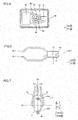
electric propulsion device 1 according to a first embodiment of the present teaching is described with reference toFigs. 1 to 14 . In the figures, arrow FWD represents the forward movement direction of a boat body, and arrow BWD represents the reverse movement direction of the boat body. - As shown in
Fig. 1 , oneelectric propulsion device 1 is arranged on each of the front and back sides of aboat body 200. Theelectric propulsion device 1 on the back side is hereinafter referred to as theelectric propulsion device 1a, and theelectric propulsion device 1 on the front side is hereinafter referred to as theelectric propulsion device 1 b. Theelectric propulsion device 1 a is mounted on an outboard motor 150 (abracket 155 of the boat body 150) arranged on the back side of theboat body 200. Theelectric propulsion device 1 b is mounted on akeel portion 220 on the front side of theboat body 200. Theboat body 200 is provided with anoperation portion 250 including a joystick or the like to operate theelectric propulsion devices operation portion 250 controls the start and stop of the operation of theelectric propulsion devices - As shown in
Fig. 2 , theoutboard motor 150 includes acase portion 151, apower source 152, apropeller 153, and an ECU (electronic control unit) 154. Electric power is supplied from abattery 210 arranged in theboat body 200 to thepower source 152 and theECU 154 through a wire (not shown). Theoutboard motor 150 is mounted on theboat body 200 through thebracket 155 including aclamp bracket 155a and aswivel bracket 155b. More specifically, theoutboard motor 150 is mounted on theswivel bracket 155b. Theclamp bracket 155a is fixed to theboat body 200, and theswivel bracket 155b is tilted with respect to theclamp bracket 155a. Thus, theoutboard motor 150 is tilted with respect to theclamp bracket 155a. Theoutboard motor 150 is mounted on theswivel bracket 155b so as to turn with respect to theswivel bracket 155b. - The
power source 152 rotates thepropeller 153 through a driving force transmission mechanism (not shown) (a drive shaft, a propeller shaft, or the like). Thepower source 152 includes a motor, for example. Alternatively, thepower source 152 may be an engine. - The
ECU 154 includes a CPU, a storage portion, etc. TheECU 154 controls the operation of theoutboard motor 150. - The structure of the
electric propulsion device 1a on the back side is now described. - As shown in
Fig. 3 , theelectric propulsion device 1 a includes aduct 2, arim 3, and a bracket 4 (seeFig. 2 ). Theelectric propulsion device 1a is a radial gap motor including theduct 2 that defines a stator and therim 3 that defines a rotor. Therim 3 and theduct 2 are arranged above a cavitation plate 160 (seeFig. 2 ) of theoutboard motor 150. - The
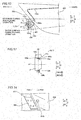
duct 2 has a cylindrical shape opened to two sides of a first side and a second side opposite to the first side. Furthermore, theduct 2 has a cylindrical shape having an opening reduced in size from the first side toward the second side. Theduct 2 is annularly formed, as viewed in an open direction. Theduct 2 is asymmetric about a plane S (seeFig. 4 ) that is perpendicular (direction Z) to the extensional direction of the rotation axis Ar of therim 3 and passes through a center position of theduct 2. Theduct 2 includes astator portion 21, a turningshaft 22, and aconnector 23 to carry electrical current. - The
stator portion 21 is annularly (seeFigs. 8 and 9 ) arranged inside ahousing 2a of theduct 2. Thestator portion 21 includes acoil 211. - The turning
shaft 22 has turningshafts shaft 22a is provided so as to protrude upward (along arrow Z1) from the outer surface of an upper portion of thehousing 2a. The turningshaft 22a is a hollow shaft internally having a space where awire 441 described later is arranged. The turningshaft 22b is provided so as to protrude downward (along arrow Z2) from the outer surface of a lower portion of thehousing 2a. Theturning shafts turning shafts duct 2 in the front-back direction of theelectric propulsion device 1 a. - The
connector 23 is provided inside thehousing 2a of theduct 2. Theconnector 23 is arranged inside the turningshaft 22a. Theconnector 23 is arranged above (along arrow Z1) thestator portion 21. As shown inFig. 4 , theconnector 23 includes awire connection portion 231 connected withwires connector 23 also includes awire connection portion 232. A wire to carry electrical current to parts provided in theduct 2 depending on the intended use is connectable to thewire connection portion 232. - As shown in
Fig. 3 , therim 3 is arranged in an inner peripheral portion of theannular duct 2 and is rotatably held by theduct 2 so as to be integrally turnable or simultaneously turnable with therim 3. Therim 3 rotates about a rotation axis Ar with respect to theduct 2. The rotation axis Ar of therim 3 is orthogonal to the turning axis As of theduct 2. Therim 3 has a circular outer frame (rotor portion 31), as viewed along the rotation axis Ar. Therim 3 includes therotor portion 31 andfins 32. Therim 3 and theduct 2 are mounted on theswivel bracket 155b (bracket 155) through the bracket 4 (seeFig. 2 ). - The
rotor portion 31 includes a plurality ofmagnets 31 a internally annularly arranged. Therim 3 defines a rotor rotatable by therotor portion 31, relative to theduct 2 that defines a stator. - A plurality of
fins 32 are provided. A clearance is formed betweenadjacent fins 32. Thefins 32 are formed integrally with the rim 3 (rotor portion 31). - As shown in
Fig. 2 , thebracket 4 holds theduct 2 from above (along arrow Z1) and from below (along arrow Z2) to support theduct 2 at two different positions. Thebracket 4 includes anupper portion 4a, alower portion 4b, and mountingportions 4c. - A lower surface portion of the
upper portion 4a includes a bearingportion 41 a (seeFig. 8 ) made of resin. Theupper portion 4a rotatably supports the turningshaft 22a of theduct 2 from above by the bearingportion 41a. As shown inFig. 5 , theupper portion 4a is provided with a turningactuator 41, adrive gear 42, a drivengear 43, aconnection portion 44, anECU 45, and a seal portion 46 (seeFig. 8 ). - The turning
actuator 41 includes an electric motor such as a servomotor, for example. The turningactuator 41 is arranged such that the rotation axis thereof is parallel to a horizontal direction. As shown inFig. 6 , the turningactuator 41 is fixed to thebracket 4 and is arranged immediately above theduct 2. As shown inFig. 7 , the turningactuator 41 is arranged at a substantially central position of theduct 2 in the right-left direction of theelectric propulsion device 1 a (in the right-left direction as viewed in the front-back direction of theelectric propulsion device 1a). The turningactuator 41 is arranged such that the rotation axis of an output shaft is substantially parallel to the horizontal direction, as shown inFig. 8 . - As shown in
Fig. 8 , thedrive gear 42 is mounted on the turningactuator 41. The turningactuator 41 drives thedrive gear 42 so as to integrally turn theduct 2 and therim 3. That is, "integrally turn" means that theduct 2 and therim 3 are simultaneously turned by the same amount in the same direction. - The driven
gear 43 is mounted on theduct 2. Specifically, the drivengear 43 is mounted on theduct 2 through theconnection portion 44. The drivengear 43 is arranged above (along arrow Z1) theduct 2 in the vicinity of theduct 2. The driving force of the turningactuator 41 is transmitted to the drivengear 43 through thedrive gear 42. Thedrive gear 42 and the drivengear 43 convert the driving force of the turningactuator 41 about the rotation axis parallel to the horizontal direction into driving force about the turning axis As (in a vertical direction). Theconnection portion 44 is fixed to the drivengear 43 at a center position (seeFig. 5 ) thereof in a plan view. The drivengear 43 rotates together with theconnection portion 44 about the turning axis As. - An upper portion of the
connection portion 44 is fixed to the drivengear 43, and a lower portion of theconnection portion 44 is fixed to the turningshaft 22a. An unshown O-ring and an unshown gel insulator are provided between theconnection portion 44 and the turningshaft 22a, and entry of external water through a clearance between theconnection portion 44 and the turningshaft 22a is significantly reduced or prevented. The upper portion and the lower portion of theconnection portion 44 have hollow shaft shapes whose outer diameters are different from each other. Theconnection portion 44 is formed such that the outer diameter of the upper portion is smaller than the outer diameter of the lower portion. Theconnection portion 44 is supported by the bracket 4 (upper portion 4a) so as to be rotatable about the turning axis As. Thewire 441 to drive the rim is provided inside theconnection portion 44. Thewire 441 is connected to theconnector 23 and is arranged above theconnector 23. Thewire 441 connects theECU 45 and theconnector 23. Thewire 442 is arranged between theconnector 23 and thecoil 211. Electrical current is carried to thecoil 211 of thestator portion 21 through thewires rim 3 rotates with respect to theduct 2. Theseal portion 46 is arranged in theupper portion 4a so as to surround the upper portion of theconnection portion 44. InFigs. 3 and8 , thewire 442 is simplified. - As shown in
Figs. 2 and8 , theECU 45 is connected to theoperation portion 250 through awire 250a. TheECU 45 controls electrical current applied to thewires actuator 41 on the basis of the operation of theoperation portion 250 of theboat body 200 by a user. TheECU 45 integrally turns theduct 2 and therim 3 clockwise or counterclockwise in the plan view on the basis of the operation of theoperation portion 250 of theboat body 200 by the user. Theduct 2 and therim 3 rotate by up to 720 degrees. - As shown in
Fig. 9 , thelower portion 4b includes a bearingportion 41b made of resin. Thelower portion 4b rotatably supports the turningshaft 22b of theduct 2 from below by the bearingportion 41 b. Thelower portion 4b and theupper portion 4a (seeFig. 8 ) support theduct 2 so as to allow theduct 2 to turn about the turning axis As that intersects with the rotation axis Ar of therim 3. Thus, theduct 2 is turned relative to thebracket 4. - As shown in
Figs. 6 and 7 , a pair of mountingportions 4c are provided. As shown inFig. 2 , respective back portions of the mountingportions 4c are connected to theupper portion 4a and thelower portion 4b. Front portions of the mountingportions 4c are mounted on the bracket 155 (swivelbracket 155b, seeFig. 2 ). Thus, theduct 2 and the rim 3 (electric propulsion device 1 a) are tilted with respect to theclamp bracket 155a together with theoutboard motor 150. The pair of mountingportions 4c each have such a width that the mountingportions 4c do not interfere with theoutboard motor 150 when theoutboard motor 150 is turned with respect to theswivel bracket 155b, as viewed from above. Thus, hindrance of theelectric propulsion device 1 a including thebracket 4 to tilting and turning theoutboard motor 150 is reduced. - The structure of the
electric propulsion device 1 b on the front side is now described. - As shown in
Fig. 12 , theelectric propulsion device 1 b includes aduct 2, arim 3, and abracket 104. Theelectric propulsion device 1b is a radial gap motor including theduct 2 and therim 3. Theelectric propulsion device 1 b basically has a structure similar to that of theelectric propulsion device 1 a (seeFig. 2 ), except for the different shape of thebracket 104. Thus, portions of theelectric propulsion device 1 b similar to those of theelectric propulsion device 1a are denoted by the same reference numerals, to omit the description. - As shown in
Fig. 12 , thebracket 104 holds theduct 2 from above and from below so as to support theduct 2 at two different positions, similarly to thebracket 4. Thebracket 104 includes anupper portion 104a, alower portion 104b, and mountingportions 104c. Theupper portion 104a and thelower portion 104b have structures similar to those of theupper portion 4a and thelower portion 4b of theelectric propulsion device 1 a on the back side, respectively, Thus, portions of theupper portion 104a similar to those of theupper portion 4a are denoted by the same reference numerals, to omit the description. Portions of thelower portion 104b similar to those of theupper portion 4b are denoted by the same reference numerals, to omit the description. - A pair of mounting
portions 104c (seeFig. 13 ) are provided. As shown inFig. 12 , respective front portions of the mountingportions 104c are connected to theupper portion 104a and thelower portion 104b. Back portions of the mountingportions 104c are fixed to an electric propulsiondevice mounting portion 280 provided in thekeel portion 220 of theboat body 200 by unshown screws. Thewire 250a connects the ECU 45 (seeFig. 5 ) and theoperation portion 250 through ahole 250b (seeFig. 14 ) provided in theboat body 200. Theelectric propulsion device 1 b is mounted by the mountingportion 104c at a position where therim 3 and theduct 2 are located below the waterline of theboat body 200 during non-planing operation (when theoutboard motor 150 is not driven) and are located above a water surface during planing operation (when theoutboard motor 150 is driven). - The turning operation of the
duct 2 is now described. - As shown in
Fig. 10 , theduct 2 turns within an angular range of 180 degrees or more about the turning axis As in the plan view by control of theECU 45 based on the operation of the operation portion 250 (seeFig. 1 ) of theboat body 200 by the user. Preferably, theduct 2 turns within an angular range of 360 degrees or more about the turning axis As in the plan view. More specifically, theduct 2 turns by 180 degrees clockwise and counterclockwise with respect to a reference position where the turning angle is 0 degrees. InFig. 10 , theduct 2 at the reference position is shown by a solid line, theduct 2 having turned by 180 degrees clockwise is shown by a dotted line, and theduct 2 having turned by 180 degrees counterclockwise is shown by a one-dot chain line. - As shown in
Fig. 11 , theduct 2 turns within an angular range of 720 degrees or less about the turning axis As in the plan view by control of theECU 45 based on the operation of the operation portion 250 (seeFig. 1 ) of theboat body 200 by the user. More specifically, theduct 2 turns by 360 degrees clockwise and counterclockwise with respect to the reference position where the turning angle is 0 degrees. InFig. 11 , theduct 2 at the reference position is shown by a solid line, theduct 2 having turned by 360 degrees clockwise is shown by a dotted line, and theduct 2 having turned by 360 degrees counterclockwise is shown by a one-dot chain line. - According to the first embodiment, the following effects are obtained.
- According to the first embodiment, the
electric propulsion device 1 is configured as hereinabove described, whereby the turningactuator 41 integrally turns theduct 2 and therim 3 so as to change the direction of generated propulsive force without providing a plurality of propellers. Furthermore, theduct 2 is turnable relative to the bracket 4 (theduct 2 is turned independently of the bracket 4) so as to change the direction of generated propulsive force. In addition, the turningactuator 41 fixed to thebracket 4 turns theduct 2 relative to thebracket 4, and hence the heights of theelectric propulsion devices duct 2 and therim 3. Consequently, the direction of generated propulsive force is changed while significantly reducing an increase in the sizes of theelectric propulsion devices - According to the first embodiment, the
electric propulsion device 1 is provided with the drivengear 43, thedrive gear 42, and the turningactuator 41 that drives thedrive gear 42 so as to integrally turn theduct 2 and therim 3. Thus, unlike the case where a steering shaft is provided, the turningactuator 41 integrally turns theduct 2 and therim 3 through thedrive gear 42 and the drivengear 43, and hence the heights of theelectric propulsion devices - According to the first embodiment, the
bracket 4 supports theduct 2 at the two different positions of theduct 2. Thus, thebracket 4 stably supports theduct 2, and hence theduct 2 is stably turned about the turning axis As. - According to the first embodiment, the rotation axis Ar of the
rim 3 is orthogonal to the turning axis As of theduct 2. Thus, the structures of therim 3 and theduct 2 are simplified. - According to the first embodiment, the turning
actuator 41 includes the electric motor. Thus, theelectric propulsion devices - According to the first embodiment, the
coil 211 is provided in theduct 2, and thewire 442 is provided so as to carry electrical current to thecoil 211. Thus, electrical current is easily carried to thecoil 211 of theduct 2. - According to the first embodiment, the
connector 23 to carry electrical current is provided in theduct 2, and thewire 442 is arranged between theconnector 23 and thecoil 211. Thus, electrical current is more easily carried to thecoil 211 of theduct 2 by theconnector 23. - According to the first embodiment, the
duct 2 is asymmetric about the plane that is perpendicular to the extensional direction of the rotation axis Ar of therim 3 and passes through the center position of theduct 2. Thus, theduct 2 has directivity such that propulsive force is efficiently generated, and hence propulsive force is efficiently generated while significantly reducing an increase in the sizes of theelectric propulsion devices duct 2 and therim 3. - According to the first embodiment, the
duct 2 turns within the angular range of 180 degrees or more about the turning axis As in the plan view. Thus, theduct 2 turns by at least 180 degrees about the turning axis As, and hence the orientations of theduct 2 and therim 3 are properly adjusted while integrally turning theduct 2 and therim 3. - According to the first embodiment, the
duct 2 turns within the angular range of 720 degrees or less about the turning axis As in the plan view. Thus, the orientations of theduct 2 and therim 3 are more freely adjusted, and torsion of thewire 441 that is connected to theconnector 23 and is arranged above theconnector 23, resulting from rotation of theduct 2 is significantly reduced or prevented. - According to the first embodiment, the
duct 2 and therim 3 are mounted on theoutboard motor 150 through thebracket 4. Thus, theduct 2 and therim 3 are easily mounted on theoutboard motor 150 by thebracket 4 to mount the turningactuator 41 without providing another bracket separately. - According to the first embodiment, the
duct 2 and therim 3 are arranged above thecavitation plate 160 of theoutboard motor 150. Thus, arrangement of theduct 2 and therim 3 below the waterline is prevented during planing operation, and hence the resistance of theduct 2 and therim 3 is significantly reduced during planing operation. - The structure of an
electric propulsion device 100 according to a second embodiment of the present teaching is now described with reference toFigs. 15 and 16 . - In the second embodiment, the
electric propulsion device 100 in which no drivengear 43 or drivegear 42 is provided is described, unlike the first embodiment in which theduct 2 and therim 3 are turned through the drivengear 43 and thedrive gear 42. Portions of theelectric propulsion device 100 similar to those of theelectric propulsion device 1 according to the aforementioned first embodiment are denoted by the same reference numerals, to omit the description. - One
electric propulsion device 100 is arranged on each of the front and back sides of aboat body 200, similarly to the first embodiment. Theelectric propulsion device 100 on the back side is hereinafter referred to as theelectric propulsion device 100a, and theelectric propulsion device 100 on the front side is hereinafter referred to as theelectric propulsion device 100b. - The structure of the
electric propulsion device 100a on the back side is described. - As shown in
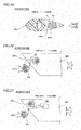
Fig. 15 , anupper portion 204a of abracket 204 includes a turningactuator 241 and acoupling portion 242. Theupper portion 204a includes aconnection portion 44, anECU 45, and aseal portion 46. - The turning
actuator 241 includes an electric motor such as a servomotor, for example. The turningactuator 241 is an axial gap motor. The turningactuator 241 includes alower housing 243, anupper housing 244, astator portion 245, arotor portion 246, and amagnet 247. The turningactuator 241 is fixed to thebracket 204 and is arranged immediately above theduct 2. The turningactuator 241 is arranged such that the rotation axis thereof is parallel to a substantially vertical direction. The rotation axis of the turningactuator 241 is arranged substantially coaxially with the turning axis As of the duct 2 (seeFig. 2 ). - The
lower housing 243 is a casing having a bottom, opened upward. - The
upper housing 244 is arranged on an upper portion of thelower housing 243. Thestator portion 245, therotor portion 246, etc. are stored in a space defined by theupper housing 244 and thelower housing 243. - The
stator portion 245 is arranged on the upper surface of thelower housing 243. Thestator portion 245 is annularly provided so as to surround the turning axis As. Thestator portion 245 includes an unshown coil. - The
rotor portion 246 is arranged at a prescribed interval in a vertical direction (direction Z) from thestator portion 245. Therotor portion 246 is annularly arranged so as to surround the turning axis As. Therotor portion 246 is plate-like. Themagnet 247 is provided on the lower surface of therotor portion 246. Acoupling portion 248 is mounted on an innerperipheral portion 246a of therotor portion 246. - The
coupling portion 242 is mounted on theduct 2 through theconnection portion 44. Thecoupling portion 242 is coupled (splined, seeFig. 16 ) to thecoupling portion 248 of therotor portion 246. Theconnection portion 44 is fixed to thecoupling portion 242 at a center position in a plan view. The driving force of the turningactuator 241 is transmitted to thecoupling portion 242 through thecoupling portion 248. Thecoupling portion 242 rotates together with theconnection portion 44 about the turning axis As. An upper portion of theconnection portion 44 is fixed to thecoupling portion 242, and a lower portion of theconnection portion 44 is fixed to a turningshaft 22a. Thus, the turningactuator 241 integrally turns theduct 2 and therim 3 through thecoupling portions - The remaining structure of the
electric propulsion device 100 according to the second embodiment is similar to that of theelectric propulsion device 1 according to the aforementioned first embodiment. - According to the second embodiment, the following effects are obtained.
- According to the second embodiment, the
electric propulsion device 100 is configured as hereinabove described, whereby the turningactuator 241 integrally turns theduct 2 and therim 3 so as to change the direction of generated propulsive force without providing a plurality of propellers. Furthermore, theduct 2 is turned relative to the bracket 204 (theduct 2 is turned independently of the bracket 204) so as to change the direction of generated propulsive force. In addition, the turningactuator 241 fixed to thebracket 204 turns theduct 2 relative to thebracket 204, and hence the heights of theelectric propulsion devices duct 2 and therim 3. Consequently, the direction of generated propulsive force is changed while significantly reducing an increase in the sizes of theelectric propulsion devices - According to the second embodiment, as hereinabove described, the turning axis As of the
duct 2 and the rotation axis of the turningactuator 241 are arranged substantially coaxially with each other. Thus, theduct 2 and the turningactuator 241 are arranged coaxially with each other and are aligned close to each other in the vertical direction. Consequently, theduct 2 and therim 3 are integrally turned while significantly reducing an increase in the sizes of theelectric propulsion devices - The embodiments disclosed this time must be considered as illustrative and modifications are further included.
- For example, while the electric propulsion device 1 (1 a, 1 b) or 100 (100a, 100b) including the radial gap motor including the
duct 2 that defines a stator and therim 3 that defines a rotor is shown in each of the aforementioned first and second embodiments, the present teaching is not restricted to this. According to the present teaching, an electric propulsion device including an SR (Switched Reluctance) motor including a duct and a rim may alternatively be employed. - While the
brackets bracket 204 supports theduct 2 at the two different positions in each of the aforementioned first and second embodiments, the present teaching is not restricted to this. According to the present teaching, the bracket may alternatively support the duct at one or three or more positions. - While the
duct 2 turns within the angular range of 180 degrees or more about the turning axis As in each of the aforementioned first and second embodiments, the present teaching is not restricted to this. According to the present teaching, the duct may alternatively turn only by less than 180 degrees about the turning axis. - While the
duct 2 turns within the angular range of 720 degrees or less about the turning axis As in each of the aforementioned first and second embodiments, the present teaching is not restricted to this. According to the present teaching, the duct may alternatively turn within an angular range of more than 720 degrees about the turning axis. - While the
duct 2 and therim 3 of theelectric propulsion device bracket 155 of the outboard motor 150) through thebracket bracket 4, as shown inFig. 17 . - While the
duct 2 and therim 3 of theelectric propulsion device bracket 155 of the outboard motor 150) in each of the aforementioned first and second embodiments, the present teaching is not restricted to this. According to the present teaching, the duct and the rim may alternatively be integrally mounted on the outboard motor. More specifically, the duct and the rim may alternatively be mounted on aspacer case 170 of theoutboard motor 150 that defines the bracket, as shown inFigs. 18 and19 . The duct and the rim are arranged in a through-hole 170a of thespacer case 170 so as to be turnable. Thus, the duct and the rim are mounted, utilizing a portion of the outboard motor as the bracket, and hence the number of components is reduced. Furthermore, the duct and the rim are arranged, utilizing an empty space of thespacer case 170 of the outboard motor. - While the
duct 2 and therim 3 of theelectric propulsion device bracket 155 of the outboard motor 150) in each of the aforementioned first and second embodiments, the present teaching is not restricted to this. According to the present teaching, the duct and the rim may alternatively be mounted on a flap of the outboard motor that serves as the bracket. - While the
duct 2 and therim 3 of theelectric propulsion device keel portion 220 of theboat body 200 in each of the aforementioned first and second embodiments, the present teaching is not restricted to this. According to the present teaching, the duct and the rim may alternatively be stored in the boat body in a state where the same are mounted on the bracket. In this case, theduct 2 and therim 3 may be stored in theboat body 200 in a state where the same are mounted on thebracket 104 by arotary storage mechanism 301 or aretractable storage mechanism 302, as shown in a modification in each ofFigs. 20 and 21 . When theduct 2 and therim 3 are stored in theboat body 200, arrangement of theduct 2 and therim 3 below the waterline is prevented during planing operation, and hence the resistance of theduct 2 and therim 3 is significantly reduced during planing operation.
Claims (15)
- An electric propulsion device comprising:a duct (2) having a cylindrical shape and that includes a stator (21);a rim (3) including a rotor (31) rotatable relative to the duct (2) and a plurality of fins (32);a bracket (4, 104, 204) that supports the duct (2) so as to allow the duct (2) to turn about a turning axis (As) that intersects with a rotation axis (Ar) of the rim (3); anda turning actuator (41, 241) configured to simultaneously turn the duct (2) and the rim (3), the turning actuator (41, 241) being fixed to the bracket (4, 104, 204), wherein the duct (2) is turnable relative to the bracket (4, 104, 204).
- An electric propulsion device according to claim 1, further comprising:a driven gear (43) mounted on the duct (2); anda drive gear (42) configured to drive the driven gear (43), whereinthe turning actuator (41) is configured to drive the drive gear (42) so as to simultaneously turn the duct (2) and the rim (3).
- An electric propulsion device according to claim 1, wherein the turning axis (As) of the duct (2) and a rotation axis (Ar) of the turning actuator (41, 241) are arranged coaxially with each other.
- An electric propulsion device according to any of claims 1 to 3, wherein the bracket (4, 104, 204) supports the duct (2) at two or more different positions of the duct (2) that are on at least two opposite sides from each other.
- An electric propulsion device according to any of claims 1 to 4, wherein the rotation axis (Ar) of the rim (3) is orthogonal to the turning axis (As) of the duct (2).
- An electric propulsion device according to any of claims 1 to 5, wherein the turning actuator (41, 241) includes an electric motor.
- An electric propulsion device according to any of claims 1 to 6, wherein the duct (2) includes a coil (211),
the electric propulsion device further comprising a wire (442) to carry electrical current to the coil (211). - An electric propulsion device according to claim 7, wherein the duct (2) includes a connector (23) to carry electrical current, and
the wire (422) is arranged between the connector (23) and the coil (211). - An electric propulsion device according to any of claims 1 to 8, wherein the duct (2) is asymmetric about a plane that is perpendicular to an extensional direction of the rotation axis (Ar) of the rim (3) and passes through a center position of the duct (2).
- An electric propulsion device according to claim 9, wherein the duct (2) is configured to be turned within an angular range of 180 degrees or more about the turning axis (As) in a plan view.
- An electric propulsion device according to claim 10, wherein the duct (2) includes a coil, and
the bracket (4, 104, 204) includes a connector (23) to carry electrical current,
the electric propulsion device further comprising a first wire (442) arranged between the connector (23) and the coil (221) to carry electrical current to the coil (211) and a second wire (441) connected to the connector (23), arranged above the connector (23), the second wire (441) is configured to provide the electrical current to the connector (23), wherein
the duct (2) is configured to be turned within an angular range of 720 degrees or less about the turning axis (As) in the plan view. - A boat with a boat body (200) and an electric propulsion device according to any of claims 1 to 11, wherein the duct (2) and the rim (3) are stored in the boat body (200) in a state where the duct (2) and the rim (3) are mounted on the bracket (4, 104, 204).
- An outboard motor with an electric propulsion device according to any of claims 1 to 12, wherein the duct (2) and the rim (3) are mounted on the outboard motor (150) through the bracket (4, 104, 204).
- An outboard motor with an electric propulsion device according to any of claims 1 to 12, wherein the duct (2) and the rim (3) are mounted in a through hole of an integrally formed spacer case of the outboard motor.
- An outboard motor according to claim 13 or 14, wherein the duct (2) and the rim (3) are arranged above a cavitation plate (160) of the outboard motor.
Applications Claiming Priority (1)
| Application Number | Priority Date | Filing Date | Title |
|---|---|---|---|
| JP2014196964A JP2016068610A (en) | 2014-09-26 | 2014-09-26 | Electric propulsion unit |
Publications (2)
| Publication Number | Publication Date |
|---|---|
| EP3000718A1 true EP3000718A1 (en) | 2016-03-30 |
| EP3000718B1 EP3000718B1 (en) | 2018-11-07 |
Family
ID=54199090
Family Applications (1)
| Application Number | Title | Priority Date | Filing Date |
|---|---|---|---|
| EP15186829.6A Active EP3000718B1 (en) | 2014-09-26 | 2015-09-25 | Electrical propulsion device |
Country Status (3)
| Country | Link |
|---|---|
| US (1) | US10202181B2 (en) |
| EP (1) | EP3000718B1 (en) |
| JP (1) | JP2016068610A (en) |
Cited By (5)
| Publication number | Priority date | Publication date | Assignee | Title |
|---|---|---|---|---|
| EP3722201A1 (en) * | 2019-04-02 | 2020-10-14 | Yamaha Hatsudoki Kabushiki Kaisha | Vessel propulsion system and vessel |
| EP3826916A4 (en) * | 2018-07-25 | 2022-04-27 | Sideshift Inc. | Stern-mounted lateral marine thruster |
| EP4177150A1 (en) * | 2021-11-04 | 2023-05-10 | Yamaha Hatsudoki Kabushiki Kaisha | Marine propulsion system and marine vessel |
| EP4177155A1 (en) * | 2021-11-04 | 2023-05-10 | Yamaha Hatsudoki Kabushiki Kaisha | Marine propulsion system |
| EP4177154A1 (en) * | 2021-11-04 | 2023-05-10 | Yamaha Hatsudoki Kabushiki Kaisha | Marine propulsion system |
Families Citing this family (7)
| Publication number | Priority date | Publication date | Assignee | Title |
|---|---|---|---|---|
| JP2018079743A (en) | 2016-11-14 | 2018-05-24 | ヤマハ発動機株式会社 | Ship propulsion unit and ship with the same |
| US11338894B1 (en) | 2019-04-10 | 2022-05-24 | Jonathan A. Bay | Auxiliary low-speed marine steering associated with inverted snorkel for underwater engine exhaust |
| US12006015B2 (en) | 2020-05-13 | 2024-06-11 | Liquid Propulsion, Llc | Thrust system for steering marine vessels |
| WO2021231809A1 (en) * | 2020-05-13 | 2021-11-18 | Liquid Propulsion, Llc | Thrust system for steering marine vessels |
| JP2022068615A (en) | 2020-10-22 | 2022-05-10 | ヤマハ発動機株式会社 | Ship operating system and ship |
| KR102611633B1 (en) * | 2022-01-17 | 2023-12-08 | (주)한국알앤드디 | Outboard unit with auxiliary propeller |
| JP2024110473A (en) | 2023-02-03 | 2024-08-16 | ヤマハ発動機株式会社 | Marine propulsion unit, ship, and plate |
Citations (7)
| Publication number | Priority date | Publication date | Assignee | Title |
|---|---|---|---|---|
| FR1529806A (en) * | 1967-05-09 | 1968-06-21 | Brissonneau & Lotz | Group formed by the combination of an electric machine and a fluid machine |
| EP0111908A2 (en) * | 1982-12-17 | 1984-06-27 | Licentia Patent-Verwaltungs-GmbH | Electrically driven ship's propeller and its use |
| US5016553A (en) * | 1989-12-04 | 1991-05-21 | Spencer William P | Vector steering control system |
| US7357687B1 (en) * | 2006-12-29 | 2008-04-15 | Navatek, Ltd. | Marine propulsion steering system |
| WO2012062699A1 (en) * | 2010-11-10 | 2012-05-18 | Siemens Aktiengesellschaft | Watercraft having a lateral-jet drive |
| US20120251353A1 (en) | 2008-11-17 | 2012-10-04 | Marinno -- Maritime Innovations Gmbh & Co. Kg | Lateral thruster for a vessel |
| JP2013100013A (en) | 2011-11-08 | 2013-05-23 | Yamaha Motor Co Ltd | Marine vessel propulsion device |
Family Cites Families (6)
| Publication number | Priority date | Publication date | Assignee | Title |
|---|---|---|---|---|
| US4200055A (en) * | 1978-04-25 | 1980-04-29 | Hydra-Troll, Inc. | Trolling driving means for boat |
| US5306183A (en) * | 1993-02-25 | 1994-04-26 | Harbor Branch Oceanographic Institute Inc. | Propulsion systems for submarine vessels |
| US5522335A (en) * | 1995-01-30 | 1996-06-04 | Westinghouse Electric Corporation | Combined azimuthing and tunnel auxillary thruster powered by integral and canned electric motor and marine vessel powered thereby |
| US6579133B1 (en) * | 2002-06-06 | 2003-06-17 | Bill Harris | Boat positioning apparatus and system |
| US6964590B1 (en) | 2004-11-06 | 2005-11-15 | Don Dongcho Ha | Lateral thrust drive unit for marine vessels |
| US7530319B1 (en) | 2008-02-29 | 2009-05-12 | Don Dongcho Ha | Lateral thruster unit for marine vessels |
-
2014
- 2014-09-26 JP JP2014196964A patent/JP2016068610A/en active Pending
-
2015
- 2015-06-22 US US14/746,167 patent/US10202181B2/en active Active
- 2015-09-25 EP EP15186829.6A patent/EP3000718B1/en active Active
Patent Citations (7)
| Publication number | Priority date | Publication date | Assignee | Title |
|---|---|---|---|---|
| FR1529806A (en) * | 1967-05-09 | 1968-06-21 | Brissonneau & Lotz | Group formed by the combination of an electric machine and a fluid machine |
| EP0111908A2 (en) * | 1982-12-17 | 1984-06-27 | Licentia Patent-Verwaltungs-GmbH | Electrically driven ship's propeller and its use |
| US5016553A (en) * | 1989-12-04 | 1991-05-21 | Spencer William P | Vector steering control system |
| US7357687B1 (en) * | 2006-12-29 | 2008-04-15 | Navatek, Ltd. | Marine propulsion steering system |
| US20120251353A1 (en) | 2008-11-17 | 2012-10-04 | Marinno -- Maritime Innovations Gmbh & Co. Kg | Lateral thruster for a vessel |
| WO2012062699A1 (en) * | 2010-11-10 | 2012-05-18 | Siemens Aktiengesellschaft | Watercraft having a lateral-jet drive |
| JP2013100013A (en) | 2011-11-08 | 2013-05-23 | Yamaha Motor Co Ltd | Marine vessel propulsion device |
Cited By (7)
| Publication number | Priority date | Publication date | Assignee | Title |
|---|---|---|---|---|
| EP3826916A4 (en) * | 2018-07-25 | 2022-04-27 | Sideshift Inc. | Stern-mounted lateral marine thruster |
| AU2019312084B2 (en) * | 2018-07-25 | 2023-06-29 | Sideshift Inc. | Stern-mounted lateral marine thruster |
| EP3722201A1 (en) * | 2019-04-02 | 2020-10-14 | Yamaha Hatsudoki Kabushiki Kaisha | Vessel propulsion system and vessel |
| US11117643B2 (en) | 2019-04-02 | 2021-09-14 | Yamaha Hatsudoki Kabushiki Kaisha | Vessel propulsion system and vessel |
| EP4177150A1 (en) * | 2021-11-04 | 2023-05-10 | Yamaha Hatsudoki Kabushiki Kaisha | Marine propulsion system and marine vessel |
| EP4177155A1 (en) * | 2021-11-04 | 2023-05-10 | Yamaha Hatsudoki Kabushiki Kaisha | Marine propulsion system |
| EP4177154A1 (en) * | 2021-11-04 | 2023-05-10 | Yamaha Hatsudoki Kabushiki Kaisha | Marine propulsion system |
Also Published As
| Publication number | Publication date |
|---|---|
| US10202181B2 (en) | 2019-02-12 |
| EP3000718B1 (en) | 2018-11-07 |
| US20160090166A1 (en) | 2016-03-31 |
| JP2016068610A (en) | 2016-05-09 |
Similar Documents
| Publication | Publication Date | Title |
|---|---|---|
| EP3000718B1 (en) | Electrical propulsion device | |
| JP5872255B2 (en) | Ship propulsion device | |
| JP3174444U (en) | Electric outboard motor | |
| JP5521708B2 (en) | Electric outboard motor | |
| US9772014B2 (en) | Steering apparatus of outboard motor and outboard motor boat | |
| JPWO2017082248A1 (en) | Ship propulsion device | |
| JP2020032871A (en) | Electric propulsion device and electric propulsion ship | |
| JP7163744B2 (en) | Robot drive mechanism and robot | |
| US8690618B2 (en) | Marine vessel propulsion apparatus | |
| KR101261867B1 (en) | Pod type propulsion device and ship with the same | |
| US9475563B2 (en) | Electric outboard motor | |
| KR101523729B1 (en) | Rudder assembly | |
| JP2006290198A (en) | Outboard motor | |
| CN110576968A (en) | aircraft and control method of aircraft | |
| EP1676612B1 (en) | Toy boat | |
| JP2011213241A (en) | Electric outboard motor | |
| JP5454309B2 (en) | Electric outboard motor | |
| KR101609195B1 (en) | Marine outboard remote steering and engine adjustment device | |
| KR20220116417A (en) | Drpm with better propulsion ability | |
| KR101422239B1 (en) | Propulsion apparatus for vessel | |
| US20220355913A1 (en) | A worm gear actuator for a marine steering apparatus | |
| KR101168280B1 (en) | Power transmitting apparatus of ship and ship using the same | |
| KR101404442B1 (en) | Auto lever device by vertical arranged gear drive | |
| JP2020006829A (en) | Outboard engine | |
| KR20200066453A (en) | Removable Coaxial Reversal Drones |
Legal Events
| Date | Code | Title | Description |
|---|---|---|---|
| PUAI | Public reference made under article 153(3) epc to a published international application that has entered the european phase |
Free format text: ORIGINAL CODE: 0009012 |
|
| AK | Designated contracting states |
Kind code of ref document: A1 Designated state(s): AL AT BE BG CH CY CZ DE DK EE ES FI FR GB GR HR HU IE IS IT LI LT LU LV MC MK MT NL NO PL PT RO RS SE SI SK SM TR |
|
| AX | Request for extension of the european patent |
Extension state: BA ME |
|
| 17P | Request for examination filed |
Effective date: 20160915 |
|
| RBV | Designated contracting states (corrected) |
Designated state(s): AL AT BE BG CH CY CZ DE DK EE ES FI FR GB GR HR HU IE IS IT LI LT LU LV MC MK MT NL NO PL PT RO RS SE SI SK SM TR |
|
| STAA | Information on the status of an ep patent application or granted ep patent |
Free format text: STATUS: EXAMINATION IS IN PROGRESS |
|
| 17Q | First examination report despatched |
Effective date: 20171024 |
|
| GRAP | Despatch of communication of intention to grant a patent |
Free format text: ORIGINAL CODE: EPIDOSNIGR1 |
|
| STAA | Information on the status of an ep patent application or granted ep patent |
Free format text: STATUS: GRANT OF PATENT IS INTENDED |
|
| INTG | Intention to grant announced |
Effective date: 20180605 |
|
| GRAS | Grant fee paid |
Free format text: ORIGINAL CODE: EPIDOSNIGR3 |
|
| GRAA | (expected) grant |
Free format text: ORIGINAL CODE: 0009210 |
|
| STAA | Information on the status of an ep patent application or granted ep patent |
Free format text: STATUS: THE PATENT HAS BEEN GRANTED |
|
| AK | Designated contracting states |
Kind code of ref document: B1 Designated state(s): AL AT BE BG CH CY CZ DE DK EE ES FI FR GB GR HR HU IE IS IT LI LT LU LV MC MK MT NL NO PL PT RO RS SE SI SK SM TR |
|
| REG | Reference to a national code |
Ref country code: GB Ref legal event code: FG4D |
|
| REG | Reference to a national code |
Ref country code: CH Ref legal event code: EP Ref country code: AT Ref legal event code: REF Ref document number: 1061738 Country of ref document: AT Kind code of ref document: T Effective date: 20181115 |
|
| REG | Reference to a national code |
Ref country code: DE Ref legal event code: R096 Ref document number: 602015019417 Country of ref document: DE |
|
| REG | Reference to a national code |
Ref country code: IE Ref legal event code: FG4D |
|
| REG | Reference to a national code |
Ref country code: NL Ref legal event code: FP |
|
| REG | Reference to a national code |
Ref country code: LT Ref legal event code: MG4D |
|
| REG | Reference to a national code |
Ref country code: AT Ref legal event code: MK05 Ref document number: 1061738 Country of ref document: AT Kind code of ref document: T Effective date: 20181107 |
|
| PG25 | Lapsed in a contracting state [announced via postgrant information from national office to epo] |
Ref country code: IS Free format text: LAPSE BECAUSE OF FAILURE TO SUBMIT A TRANSLATION OF THE DESCRIPTION OR TO PAY THE FEE WITHIN THE PRESCRIBED TIME-LIMIT Effective date: 20190307 Ref country code: FI Free format text: LAPSE BECAUSE OF FAILURE TO SUBMIT A TRANSLATION OF THE DESCRIPTION OR TO PAY THE FEE WITHIN THE PRESCRIBED TIME-LIMIT Effective date: 20181107 Ref country code: HR Free format text: LAPSE BECAUSE OF FAILURE TO SUBMIT A TRANSLATION OF THE DESCRIPTION OR TO PAY THE FEE WITHIN THE PRESCRIBED TIME-LIMIT Effective date: 20181107 Ref country code: AT Free format text: LAPSE BECAUSE OF FAILURE TO SUBMIT A TRANSLATION OF THE DESCRIPTION OR TO PAY THE FEE WITHIN THE PRESCRIBED TIME-LIMIT Effective date: 20181107 Ref country code: NO Free format text: LAPSE BECAUSE OF FAILURE TO SUBMIT A TRANSLATION OF THE DESCRIPTION OR TO PAY THE FEE WITHIN THE PRESCRIBED TIME-LIMIT Effective date: 20190207 Ref country code: LV Free format text: LAPSE BECAUSE OF FAILURE TO SUBMIT A TRANSLATION OF THE DESCRIPTION OR TO PAY THE FEE WITHIN THE PRESCRIBED TIME-LIMIT Effective date: 20181107 Ref country code: BG Free format text: LAPSE BECAUSE OF FAILURE TO SUBMIT A TRANSLATION OF THE DESCRIPTION OR TO PAY THE FEE WITHIN THE PRESCRIBED TIME-LIMIT Effective date: 20190207 Ref country code: LT Free format text: LAPSE BECAUSE OF FAILURE TO SUBMIT A TRANSLATION OF THE DESCRIPTION OR TO PAY THE FEE WITHIN THE PRESCRIBED TIME-LIMIT Effective date: 20181107 Ref country code: ES Free format text: LAPSE BECAUSE OF FAILURE TO SUBMIT A TRANSLATION OF THE DESCRIPTION OR TO PAY THE FEE WITHIN THE PRESCRIBED TIME-LIMIT Effective date: 20181107 |
|
| PG25 | Lapsed in a contracting state [announced via postgrant information from national office to epo] |
Ref country code: PT Free format text: LAPSE BECAUSE OF FAILURE TO SUBMIT A TRANSLATION OF THE DESCRIPTION OR TO PAY THE FEE WITHIN THE PRESCRIBED TIME-LIMIT Effective date: 20190307 Ref country code: AL Free format text: LAPSE BECAUSE OF FAILURE TO SUBMIT A TRANSLATION OF THE DESCRIPTION OR TO PAY THE FEE WITHIN THE PRESCRIBED TIME-LIMIT Effective date: 20181107 Ref country code: GR Free format text: LAPSE BECAUSE OF FAILURE TO SUBMIT A TRANSLATION OF THE DESCRIPTION OR TO PAY THE FEE WITHIN THE PRESCRIBED TIME-LIMIT Effective date: 20190208 Ref country code: SE Free format text: LAPSE BECAUSE OF FAILURE TO SUBMIT A TRANSLATION OF THE DESCRIPTION OR TO PAY THE FEE WITHIN THE PRESCRIBED TIME-LIMIT Effective date: 20181107 Ref country code: RS Free format text: LAPSE BECAUSE OF FAILURE TO SUBMIT A TRANSLATION OF THE DESCRIPTION OR TO PAY THE FEE WITHIN THE PRESCRIBED TIME-LIMIT Effective date: 20181107 |
|
| PG25 | Lapsed in a contracting state [announced via postgrant information from national office to epo] |
Ref country code: CZ Free format text: LAPSE BECAUSE OF FAILURE TO SUBMIT A TRANSLATION OF THE DESCRIPTION OR TO PAY THE FEE WITHIN THE PRESCRIBED TIME-LIMIT Effective date: 20181107 Ref country code: IT Free format text: LAPSE BECAUSE OF FAILURE TO SUBMIT A TRANSLATION OF THE DESCRIPTION OR TO PAY THE FEE WITHIN THE PRESCRIBED TIME-LIMIT Effective date: 20181107 Ref country code: PL Free format text: LAPSE BECAUSE OF FAILURE TO SUBMIT A TRANSLATION OF THE DESCRIPTION OR TO PAY THE FEE WITHIN THE PRESCRIBED TIME-LIMIT Effective date: 20181107 Ref country code: DK Free format text: LAPSE BECAUSE OF FAILURE TO SUBMIT A TRANSLATION OF THE DESCRIPTION OR TO PAY THE FEE WITHIN THE PRESCRIBED TIME-LIMIT Effective date: 20181107 |
|
| REG | Reference to a national code |
Ref country code: DE Ref legal event code: R097 Ref document number: 602015019417 Country of ref document: DE |
|
| PG25 | Lapsed in a contracting state [announced via postgrant information from national office to epo] |
Ref country code: EE Free format text: LAPSE BECAUSE OF FAILURE TO SUBMIT A TRANSLATION OF THE DESCRIPTION OR TO PAY THE FEE WITHIN THE PRESCRIBED TIME-LIMIT Effective date: 20181107 Ref country code: SM Free format text: LAPSE BECAUSE OF FAILURE TO SUBMIT A TRANSLATION OF THE DESCRIPTION OR TO PAY THE FEE WITHIN THE PRESCRIBED TIME-LIMIT Effective date: 20181107 Ref country code: SK Free format text: LAPSE BECAUSE OF FAILURE TO SUBMIT A TRANSLATION OF THE DESCRIPTION OR TO PAY THE FEE WITHIN THE PRESCRIBED TIME-LIMIT Effective date: 20181107 Ref country code: RO Free format text: LAPSE BECAUSE OF FAILURE TO SUBMIT A TRANSLATION OF THE DESCRIPTION OR TO PAY THE FEE WITHIN THE PRESCRIBED TIME-LIMIT Effective date: 20181107 |
|
| PLBE | No opposition filed within time limit |
Free format text: ORIGINAL CODE: 0009261 |
|
| STAA | Information on the status of an ep patent application or granted ep patent |
Free format text: STATUS: NO OPPOSITION FILED WITHIN TIME LIMIT |
|
| 26N | No opposition filed |
Effective date: 20190808 |
|
| PG25 | Lapsed in a contracting state [announced via postgrant information from national office to epo] |
Ref country code: SI Free format text: LAPSE BECAUSE OF FAILURE TO SUBMIT A TRANSLATION OF THE DESCRIPTION OR TO PAY THE FEE WITHIN THE PRESCRIBED TIME-LIMIT Effective date: 20181107 |
|
| PG25 | Lapsed in a contracting state [announced via postgrant information from national office to epo] |
Ref country code: TR Free format text: LAPSE BECAUSE OF FAILURE TO SUBMIT A TRANSLATION OF THE DESCRIPTION OR TO PAY THE FEE WITHIN THE PRESCRIBED TIME-LIMIT Effective date: 20181107 |
|
| PG25 | Lapsed in a contracting state [announced via postgrant information from national office to epo] |
Ref country code: MC Free format text: LAPSE BECAUSE OF FAILURE TO SUBMIT A TRANSLATION OF THE DESCRIPTION OR TO PAY THE FEE WITHIN THE PRESCRIBED TIME-LIMIT Effective date: 20181107 |
|
| REG | Reference to a national code |
Ref country code: CH Ref legal event code: PL |
|
| PG25 | Lapsed in a contracting state [announced via postgrant information from national office to epo] |
Ref country code: IE Free format text: LAPSE BECAUSE OF NON-PAYMENT OF DUE FEES Effective date: 20190925 Ref country code: CH Free format text: LAPSE BECAUSE OF NON-PAYMENT OF DUE FEES Effective date: 20190930 Ref country code: LU Free format text: LAPSE BECAUSE OF NON-PAYMENT OF DUE FEES Effective date: 20190925 Ref country code: LI Free format text: LAPSE BECAUSE OF NON-PAYMENT OF DUE FEES Effective date: 20190930 |
|
| REG | Reference to a national code |
Ref country code: BE Ref legal event code: MM Effective date: 20190930 |
|
| PG25 | Lapsed in a contracting state [announced via postgrant information from national office to epo] |
Ref country code: BE Free format text: LAPSE BECAUSE OF NON-PAYMENT OF DUE FEES Effective date: 20190930 |
|
| GBPC | Gb: european patent ceased through non-payment of renewal fee |
Effective date: 20190925 |
|
| PG25 | Lapsed in a contracting state [announced via postgrant information from national office to epo] |
Ref country code: GB Free format text: LAPSE BECAUSE OF NON-PAYMENT OF DUE FEES Effective date: 20190925 |
|
| PG25 | Lapsed in a contracting state [announced via postgrant information from national office to epo] |
Ref country code: CY Free format text: LAPSE BECAUSE OF FAILURE TO SUBMIT A TRANSLATION OF THE DESCRIPTION OR TO PAY THE FEE WITHIN THE PRESCRIBED TIME-LIMIT Effective date: 20181107 |
|
| PG25 | Lapsed in a contracting state [announced via postgrant information from national office to epo] |
Ref country code: MT Free format text: LAPSE BECAUSE OF FAILURE TO SUBMIT A TRANSLATION OF THE DESCRIPTION OR TO PAY THE FEE WITHIN THE PRESCRIBED TIME-LIMIT Effective date: 20181107 Ref country code: HU Free format text: LAPSE BECAUSE OF FAILURE TO SUBMIT A TRANSLATION OF THE DESCRIPTION OR TO PAY THE FEE WITHIN THE PRESCRIBED TIME-LIMIT; INVALID AB INITIO Effective date: 20150925 |
|
| PG25 | Lapsed in a contracting state [announced via postgrant information from national office to epo] |
Ref country code: MK Free format text: LAPSE BECAUSE OF FAILURE TO SUBMIT A TRANSLATION OF THE DESCRIPTION OR TO PAY THE FEE WITHIN THE PRESCRIBED TIME-LIMIT Effective date: 20181107 |
|
| P01 | Opt-out of the competence of the unified patent court (upc) registered |
Effective date: 20230527 |
|
| PGFP | Annual fee paid to national office [announced via postgrant information from national office to epo] |
Ref country code: NL Payment date: 20230920 Year of fee payment: 9 |
|
| PGFP | Annual fee paid to national office [announced via postgrant information from national office to epo] |
Ref country code: FR Payment date: 20230928 Year of fee payment: 9 Ref country code: DE Payment date: 20230920 Year of fee payment: 9 |