JP2013010679A - Method and apparatus for purifying argon gas - Google Patents
Method and apparatus for purifying argon gas Download PDFInfo
- Publication number
- JP2013010679A JP2013010679A JP2011173935A JP2011173935A JP2013010679A JP 2013010679 A JP2013010679 A JP 2013010679A JP 2011173935 A JP2011173935 A JP 2011173935A JP 2011173935 A JP2011173935 A JP 2011173935A JP 2013010679 A JP2013010679 A JP 2013010679A
- Authority
- JP
- Japan
- Prior art keywords
- argon gas
- oxygen
- carbon monoxide
- adsorption
- reactor
- Prior art date
- Legal status (The legal status is an assumption and is not a legal conclusion. Google has not performed a legal analysis and makes no representation as to the accuracy of the status listed.)
- Granted
Links
Images


Classifications
-
- C—CHEMISTRY; METALLURGY
- C01—INORGANIC CHEMISTRY
- C01B—NON-METALLIC ELEMENTS; COMPOUNDS THEREOF; METALLOIDS OR COMPOUNDS THEREOF NOT COVERED BY SUBCLASS C01C
- C01B23/00—Noble gases; Compounds thereof
- C01B23/001—Purification or separation processes of noble gases
- C01B23/0036—Physical processing only
- C01B23/0052—Physical processing only by adsorption in solids
- C01B23/0057—Physical processing only by adsorption in solids characterised by the adsorbent
- C01B23/0063—Carbon based materials
-
- B—PERFORMING OPERATIONS; TRANSPORTING
- B01—PHYSICAL OR CHEMICAL PROCESSES OR APPARATUS IN GENERAL
- B01D—SEPARATION
- B01D53/00—Separation of gases or vapours; Recovering vapours of volatile solvents from gases; Chemical or biological purification of waste gases, e.g. engine exhaust gases, smoke, fumes, flue gases, aerosols
- B01D53/02—Separation of gases or vapours; Recovering vapours of volatile solvents from gases; Chemical or biological purification of waste gases, e.g. engine exhaust gases, smoke, fumes, flue gases, aerosols by adsorption, e.g. preparative gas chromatography
- B01D53/04—Separation of gases or vapours; Recovering vapours of volatile solvents from gases; Chemical or biological purification of waste gases, e.g. engine exhaust gases, smoke, fumes, flue gases, aerosols by adsorption, e.g. preparative gas chromatography with stationary adsorbents
- B01D53/0454—Controlling adsorption
-
- B—PERFORMING OPERATIONS; TRANSPORTING
- B01—PHYSICAL OR CHEMICAL PROCESSES OR APPARATUS IN GENERAL
- B01J—CHEMICAL OR PHYSICAL PROCESSES, e.g. CATALYSIS OR COLLOID CHEMISTRY; THEIR RELEVANT APPARATUS
- B01J23/00—Catalysts comprising metals or metal oxides or hydroxides, not provided for in group B01J21/00
- B01J23/38—Catalysts comprising metals or metal oxides or hydroxides, not provided for in group B01J21/00 of noble metals
- B01J23/40—Catalysts comprising metals or metal oxides or hydroxides, not provided for in group B01J21/00 of noble metals of the platinum group metals
- B01J23/44—Palladium
-
- B—PERFORMING OPERATIONS; TRANSPORTING
- B01—PHYSICAL OR CHEMICAL PROCESSES OR APPARATUS IN GENERAL
- B01J—CHEMICAL OR PHYSICAL PROCESSES, e.g. CATALYSIS OR COLLOID CHEMISTRY; THEIR RELEVANT APPARATUS
- B01J23/00—Catalysts comprising metals or metal oxides or hydroxides, not provided for in group B01J21/00
- B01J23/38—Catalysts comprising metals or metal oxides or hydroxides, not provided for in group B01J21/00 of noble metals
- B01J23/40—Catalysts comprising metals or metal oxides or hydroxides, not provided for in group B01J21/00 of noble metals of the platinum group metals
- B01J23/46—Ruthenium, rhodium, osmium or iridium
- B01J23/462—Ruthenium
-
- B—PERFORMING OPERATIONS; TRANSPORTING
- B01—PHYSICAL OR CHEMICAL PROCESSES OR APPARATUS IN GENERAL
- B01D—SEPARATION
- B01D2253/00—Adsorbents used in seperation treatment of gases and vapours
- B01D2253/10—Inorganic adsorbents
- B01D2253/102—Carbon
-
- B—PERFORMING OPERATIONS; TRANSPORTING
- B01—PHYSICAL OR CHEMICAL PROCESSES OR APPARATUS IN GENERAL
- B01D—SEPARATION
- B01D2253/00—Adsorbents used in seperation treatment of gases and vapours
- B01D2253/10—Inorganic adsorbents
- B01D2253/104—Alumina
-
- B—PERFORMING OPERATIONS; TRANSPORTING
- B01—PHYSICAL OR CHEMICAL PROCESSES OR APPARATUS IN GENERAL
- B01D—SEPARATION
- B01D2253/00—Adsorbents used in seperation treatment of gases and vapours
- B01D2253/10—Inorganic adsorbents
- B01D2253/106—Silica or silicates
- B01D2253/108—Zeolites
-
- B—PERFORMING OPERATIONS; TRANSPORTING
- B01—PHYSICAL OR CHEMICAL PROCESSES OR APPARATUS IN GENERAL
- B01D—SEPARATION
- B01D2256/00—Main component in the product gas stream after treatment
- B01D2256/18—Noble gases
-
- B—PERFORMING OPERATIONS; TRANSPORTING
- B01—PHYSICAL OR CHEMICAL PROCESSES OR APPARATUS IN GENERAL
- B01D—SEPARATION
- B01D2257/00—Components to be removed
- B01D2257/10—Single element gases other than halogens
- B01D2257/102—Nitrogen
-
- B—PERFORMING OPERATIONS; TRANSPORTING
- B01—PHYSICAL OR CHEMICAL PROCESSES OR APPARATUS IN GENERAL
- B01D—SEPARATION
- B01D2257/00—Components to be removed
- B01D2257/50—Carbon oxides
- B01D2257/502—Carbon monoxide
-
- B—PERFORMING OPERATIONS; TRANSPORTING
- B01—PHYSICAL OR CHEMICAL PROCESSES OR APPARATUS IN GENERAL
- B01D—SEPARATION
- B01D2257/00—Components to be removed
- B01D2257/50—Carbon oxides
- B01D2257/504—Carbon dioxide
-
- Y—GENERAL TAGGING OF NEW TECHNOLOGICAL DEVELOPMENTS; GENERAL TAGGING OF CROSS-SECTIONAL TECHNOLOGIES SPANNING OVER SEVERAL SECTIONS OF THE IPC; TECHNICAL SUBJECTS COVERED BY FORMER USPC CROSS-REFERENCE ART COLLECTIONS [XRACs] AND DIGESTS
- Y02—TECHNOLOGIES OR APPLICATIONS FOR MITIGATION OR ADAPTATION AGAINST CLIMATE CHANGE
- Y02C—CAPTURE, STORAGE, SEQUESTRATION OR DISPOSAL OF GREENHOUSE GASES [GHG]
- Y02C20/00—Capture or disposal of greenhouse gases
- Y02C20/40—Capture or disposal of greenhouse gases of CO2
-
- Y—GENERAL TAGGING OF NEW TECHNOLOGICAL DEVELOPMENTS; GENERAL TAGGING OF CROSS-SECTIONAL TECHNOLOGIES SPANNING OVER SEVERAL SECTIONS OF THE IPC; TECHNICAL SUBJECTS COVERED BY FORMER USPC CROSS-REFERENCE ART COLLECTIONS [XRACs] AND DIGESTS
- Y02—TECHNOLOGIES OR APPLICATIONS FOR MITIGATION OR ADAPTATION AGAINST CLIMATE CHANGE
- Y02P—CLIMATE CHANGE MITIGATION TECHNOLOGIES IN THE PRODUCTION OR PROCESSING OF GOODS
- Y02P20/00—Technologies relating to chemical industry
- Y02P20/151—Reduction of greenhouse gas [GHG] emissions, e.g. CO2
-
- Y—GENERAL TAGGING OF NEW TECHNOLOGICAL DEVELOPMENTS; GENERAL TAGGING OF CROSS-SECTIONAL TECHNOLOGIES SPANNING OVER SEVERAL SECTIONS OF THE IPC; TECHNICAL SUBJECTS COVERED BY FORMER USPC CROSS-REFERENCE ART COLLECTIONS [XRACs] AND DIGESTS
- Y02—TECHNOLOGIES OR APPLICATIONS FOR MITIGATION OR ADAPTATION AGAINST CLIMATE CHANGE
- Y02P—CLIMATE CHANGE MITIGATION TECHNOLOGIES IN THE PRODUCTION OR PROCESSING OF GOODS
- Y02P20/00—Technologies relating to chemical industry
- Y02P20/50—Improvements relating to the production of bulk chemicals
Abstract
Description
本発明は、不純物として少なくとも酸素、水素、一酸化炭素、炭化水素、油分および窒素を含有するアルゴンガスを精製する方法と装置に関する。 The present invention relates to a method and apparatus for purifying argon gas containing at least oxygen, hydrogen, carbon monoxide, hydrocarbons, oil and nitrogen as impurities.
例えば、シリコン単結晶引上げ炉、セラミック焼結炉、製鋼用真空脱ガス設備、太陽電池用シリコンプラズマ溶解装置、多結晶シリコン鋳造炉のような設備においては、アルゴンガスが炉内雰囲気ガス等として使用されている。そのような設備から再利用のため回収されたアルゴンガスは、水素、一酸化炭素、空気などの混入により純度が低下している。そこで、回収されたアルゴンガスの純度を高めるため、混入した不純物を吸着剤に吸着させることが行われている。さらに、そのような不純物の吸着を効率良く行うため、吸着処理の前処理として、不純物中の酸素と可燃成分とを反応させて二酸化炭素と水に変性させることが提案されている(特許文献1、2参照)。 For example, in equipment such as silicon single crystal pulling furnace, ceramic sintering furnace, vacuum degassing equipment for steel making, silicon plasma melting equipment for solar cells, polycrystalline silicon casting furnace, argon gas is used as atmosphere gas in the furnace Has been. The purity of argon gas collected for reuse from such facilities is reduced due to the incorporation of hydrogen, carbon monoxide, air, and the like. Therefore, in order to increase the purity of the recovered argon gas, the admixed impurities are adsorbed on the adsorbent. Furthermore, in order to efficiently adsorb such impurities, it has been proposed to react oxygen in the impurities and combustible components to denature them into carbon dioxide and water as a pretreatment of the adsorption treatment (Patent Document 1). 2).
特許文献1に開示された方法においては、アルゴンガスにおける酸素の量を、水素、一酸化炭素等の可燃成分を完全燃焼させるのに必要な化学量論量よりも僅かに少なくなるよう調節し、次に、一酸化炭素と酸素との反応よりも水素と酸素との反応を優先させるパラジウムまたは金を触媒として、アルゴンガスにおける酸素を一酸化炭素、水素等と反応させ、これにより、一酸化炭素のみが残留された状態で二酸化炭素と水を生成している。次に、アルゴンガスに含有される二酸化炭素と水を常温で吸着剤に吸着させ、しかる後に、アルゴンガスに含有される一酸化炭素と窒素を−10℃〜−50℃の温度で吸着剤に吸着させている。
In the method disclosed in
特許文献2に開示された方法においては、アルゴンガスにおける酸素の量を、水素、一酸化炭素等の可燃成分を完全燃焼させるのに十分な量とし、次に、パラジウム系の触媒を用いてアルゴンガスにおける酸素を一酸化炭素、水素等と反応させることで、酸素が残留された状態で二酸化炭素と水を生成している。次に、アルゴンガスに含有される二酸化炭素と水を常温で吸着剤に吸着させ、しかる後に、アルゴンガスに含有される酸素と窒素を−170℃程度の温度で吸着剤に吸着させている。
In the method disclosed in
特許文献3に開示された方法においては、単結晶製造炉等から排出されるアルゴンガスに油分が含有される場合、その油分を活性炭等が入った油除去筒、油除去フィルターを用いて除去している。次に、触媒筒に導入されたアルゴンガス中の酸素を添加水素と反応させて水に転化している。次に、吸着筒に導入されたアルゴンガス中の水と二酸化炭素を吸着除去し、しかる後に精留操作によって精製している。
In the method disclosed in
特許文献4に開示された方法においては、一酸化炭素、水素、酸素、窒素を不純物として含むアルゴンガスを精製するため、アルゴンガスにおける一酸化炭素と水素を酸素と反応させることで、一酸化炭素を残存させた状態で二酸化炭素と水を生成している。次に、アルゴンガスにおける二酸化炭素、水、窒素および一酸化炭素を10〜50℃で吸着剤に吸着させ、その吸着剤を150〜400℃で再生している。また、アルゴンガスにおける窒素を吸着するため、吸着剤として銅イオン交換ZSM−5型ゼオライト(銅イオン交換率121%)を用いている。 In the method disclosed in Patent Document 4, in order to purify an argon gas containing carbon monoxide, hydrogen, oxygen, and nitrogen as impurities, carbon monoxide and hydrogen in the argon gas are reacted with oxygen to obtain carbon monoxide. Carbon dioxide and water are produced in a state where the water remains. Next, carbon dioxide, water, nitrogen and carbon monoxide in argon gas are adsorbed on the adsorbent at 10 to 50 ° C., and the adsorbent is regenerated at 150 to 400 ° C. Moreover, in order to adsorb | suck nitrogen in argon gas, the copper ion exchange ZSM-5 type zeolite (copper ion exchange rate 121%) is used as an adsorbent.
特許文献1に記載の方法では、前処理の第1段階の反応においてアルゴンガス中に一酸化炭素が残留された状態で二酸化炭素と水を生成している。しかし、アルゴンガスに含有される炭化水素が多い場合、反応温度を高くする必要があるため一酸化炭素も酸素と反応してしまい、一酸化炭素を残留させることが困難である。そのため、後の常温下での吸着処理では水素を吸着除去できないため、アルゴンガス中に水素が残留し、アルゴンガスを高純度に精製できないという問題がある。
In the method described in
特許文献2に記載の方法では、前処理の段階でアルゴンガスに不純物として含まれる酸素の量を水素、一酸化炭素等を完全燃焼させるのに十分な量とすることで、酸素が残留された状態で二酸化炭素と水を生成している。しかし、その後に、この残留した酸素を吸着するには吸着時の温度を−170℃程度まで低下させる必要がある。すなわち、吸着処理の前処理の段階で酸素を残留させるため、吸着処理の際の冷却エネルギーが増大し、精製負荷が大きくなるという問題がある。
In the method described in
特許文献3に記載の方法では、アルゴンガスに含有される油分を活性炭に吸着させることで除去している。しかし、アルゴンガスを回収する際に、例えば気密性保持等のためにオイルを用いる油回転真空ポンプのような機器を使用する場合、オイルが熱分解した炭化水素成分が発生し、オイル除去用ミストセパレーターがあっても、ミストセパレーターを抜けてしまう。そうすると、アルゴンガスに含有される油分に由来する炭化水素は、メタンが数十ppm以上、炭素数2〜5の炭化水素(C2〜C5)が炭素数1の炭化水素(C1)換算で数百ppm以上と非常に多くなる。メタンは活性炭に吸着されず、炭素数2〜5の炭化水素も殆ど活性炭に吸着されることなく触媒筒を抜けることから、その後の精留負荷が増大するという欠点がある。
In the method described in
特許文献4は、アルゴンガスに含有される油分や油分の分解により副生される炭化水素の除去については何ら開示していない。 Patent Document 4 does not disclose any oil contained in argon gas or removal of by-product hydrocarbons by decomposition of the oil.
本発明は、上記のような従来技術の問題を解決できるアルゴンガスの精製方法および精製装置を提供することを目的とする。 An object of the present invention is to provide an argon gas refining method and a refining apparatus that can solve the above-described problems of the prior art.
本発明方法は、少なくとも酸素、水素、一酸化炭素、炭化水素、油分および窒素を不純物として含有するアルゴンガスを精製する方法であって、前記アルゴンガスにおける炭化水素の一部と油分とを活性炭に吸着させ、次に、前記アルゴンガスにおける酸素量が、前記アルゴンガスにおける水素、一酸化炭素、および炭化水素の全てと反応するのに必要な設定量を超えるか否かを判定し、前記アルゴンガスにおける酸素量が前記設定量以下である場合、前記設定量を超えるように酸素を添加し、次に、前記アルゴンガスにおける一酸化炭素、水素、および炭化水素と酸素とを触媒を用いて反応させることで、酸素が残留された状態で二酸化炭素と水を生成し、次に、前記アルゴンガス中に残留した酸素の全てと反応するのに必要な設定量を超えるように、一酸化炭素を添加し、次に、前記アルゴンガスにおける酸素と一酸化炭素とをルテニウム触媒、パラジウム触媒、又はこれらの混合触媒を用いて反応させることで、一酸化炭素が残留された状態で二酸化炭素を生成し、次に、前記アルゴンガスにおける少なくとも一酸化炭素、二酸化炭素、水、および窒素を、圧力スイング吸着法により吸着剤に吸着させることを特徴とする。
本発明によれば、アルゴンガスに含有される油分は活性炭により吸着され、さらに、油分に由来する炭化水素の一部も活性炭により吸着され、特に炭素数が1 〜5以外の炭化水素が活性炭により効果的に吸着される。これにより、アルゴンガスにおける炭化水素量を低減することで、後の炭化水素と酸素との反応により生成される水と二酸化炭素の量を低減し、後の吸着負荷を軽減できる。また、アルゴンガス中の水素、一酸化炭素、および炭化水素を酸素と反応させ、過剰な酸素を残留させた状態で二酸化炭素と水を生成した後に、その酸素残留を除くため、新たに一酸化炭素を添加して二酸化炭素を生成させる。その反応触媒としてルテニウム触媒、パラジウム触媒、又はこれらの混合触媒を用いることで、水と一酸化炭素との反応により水素が生じるのを防止できる。これにより、吸着装置による吸着処理の前処理の段階において、吸着処理では除去困難な水素がアルゴンガスに残留するのを防止できるので、アルゴンガスを高純度に精製することが可能になる。さらに、その残留酸素を添加一酸化炭素と反応させることで、吸着装置による吸着処理の前処理の段階でアルゴンガスから酸素を除去できるので、精製負荷を低減できる。
The method of the present invention is a method for purifying an argon gas containing at least oxygen, hydrogen, carbon monoxide, hydrocarbon, oil and nitrogen as impurities, wherein a part of the hydrocarbon and the oil in the argon gas are converted into activated carbon. Adsorb and then determine whether the amount of oxygen in the argon gas exceeds a set amount necessary to react with all of hydrogen, carbon monoxide, and hydrocarbons in the argon gas; When the amount of oxygen in the gas is less than or equal to the set amount, oxygen is added so as to exceed the set amount, and then carbon monoxide, hydrogen, and hydrocarbon in the argon gas are reacted with oxygen using a catalyst. This produces carbon dioxide and water with oxygen remaining, and then exceeds the set amount necessary to react with all of the oxygen remaining in the argon gas. Then, carbon monoxide is added, and then oxygen and carbon monoxide in the argon gas are reacted using a ruthenium catalyst, a palladium catalyst, or a mixed catalyst thereof, so that carbon monoxide remains. Then, carbon dioxide is produced in the state, and then at least carbon monoxide, carbon dioxide, water, and nitrogen in the argon gas are adsorbed on the adsorbent by a pressure swing adsorption method.
According to the present invention, the oil contained in the argon gas is adsorbed by the activated carbon, and some of the hydrocarbons derived from the oil are also adsorbed by the activated carbon. Particularly, hydrocarbons other than those having 1 to 5 carbon atoms are adsorbed by the activated carbon. Adsorbed effectively. Thereby, by reducing the amount of hydrocarbon in the argon gas, the amount of water and carbon dioxide produced by the subsequent reaction of hydrocarbon and oxygen can be reduced, and the subsequent adsorption load can be reduced. In addition, after reacting hydrogen, carbon monoxide, and hydrocarbons in argon gas with oxygen to produce carbon dioxide and water with excess oxygen remaining, new oxygen monoxide is removed to remove the residual oxygen. Carbon is added to produce carbon dioxide. By using a ruthenium catalyst, a palladium catalyst, or a mixed catalyst thereof as the reaction catalyst, hydrogen can be prevented from being generated by the reaction between water and carbon monoxide. Thereby, in the pretreatment stage of the adsorption treatment by the adsorption device, hydrogen that is difficult to remove by the adsorption treatment can be prevented from remaining in the argon gas, so that the argon gas can be purified with high purity. Furthermore, by reacting the residual oxygen with the added carbon monoxide, oxygen can be removed from the argon gas at the pretreatment stage of the adsorption treatment by the adsorption device, so that the purification load can be reduced.
本発明においては、前記アルゴンガスにおける一酸化炭素、水素、および炭化水素と酸素とを反応させるための前記触媒として、パラジウムを用いるのが好ましい。これにより、パラジウムは耐熱性が良く反応性が高いので、アルゴンガスがメタンのような低級炭化水素を多く含む場合、反応温度を高くして十分に反応を進行させ、アルゴンガスにおける炭化水素を効果的に低減できる。 In the present invention, it is preferable to use palladium as the catalyst for reacting carbon monoxide, hydrogen, and hydrocarbon with oxygen in the argon gas. As a result, palladium has high heat resistance and high reactivity. Therefore, when the argon gas contains a large amount of lower hydrocarbons such as methane, the reaction is sufficiently performed by increasing the reaction temperature, and the hydrocarbons in the argon gas are effective. Can be reduced.
本発明においては、前記圧力スイング吸着法のために用いる前記吸着剤としてX型ゼオライトを用いるのが好ましい。X型ゼオライトの使用により、一酸化炭素、二酸化炭素、水、および窒素だけでなく炭化水素の吸着効果が高くなる。よって、吸着装置による吸着処理の前段階においてアルゴンガスに炭化水素が残留したとしても、その炭化水素を圧力スイング吸着法により吸着剤に効果的に吸着させることができる。 In the present invention, X-type zeolite is preferably used as the adsorbent used for the pressure swing adsorption method. The use of X-type zeolite increases the adsorption effect of hydrocarbons as well as carbon monoxide, carbon dioxide, water and nitrogen. Therefore, even if hydrocarbons remain in the argon gas in the previous stage of the adsorption process by the adsorption device, the hydrocarbons can be effectively adsorbed by the adsorbent by the pressure swing adsorption method.
あるいは本発明においては、前記圧力スイング吸着法のために用いる前記吸着剤として活性アルミナとX型ゼオライトとを用いるのが好ましい。吸着剤として活性アルミナを用いることで水分および二酸化炭素の吸着および脱着ができるので、X型ゼオライトによる一酸化炭素、窒素および炭化水素の吸着効果を高くできる。すなわち、二酸化炭素はX型ゼオライトからの脱着が比較的困難であり、X型ゼオライトの吸着効果を低減させる。吸着効果を高めるためにPSAユニットに充填するX型ゼオライトを増やすと、昇圧用の圧縮機等の能力も大きくしなければならないことから、PSAユニットが大型化して効率が低下するという問題がある。これに対し、活性アルミナにより二酸化炭素を吸着することで、X型ゼオライトの吸着効果を高くできる。これにより、吸着装置による吸着処理の前段階においてアルゴンガスに炭化水素が残留したとしても、PSAユニットを大型することなく炭化水素を圧力スイング吸着法により吸着剤に効果的に吸着させることができる。しかも、圧力スイング吸着法による一酸化炭素と窒素の吸着効果を高くできるので、TSAユニットを用いることなく、アルゴンガスを低エネルギーで高純度に精製できる。
この場合、活性アルミナのX型ゼオライトに対する重量比が小さくなると窒素、炭化水素の吸着破過時間が短くなり、大きくなると吸着破過時間が長くなる。好ましくは、前記活性アルミナと前記X型ゼオライトとを、層状にして配置し、前記活性アルミナと前記X型ゼオライトとの重量比を5/95〜30/70にする。これにより、前記アルゴンガスにおける炭化水素を前記圧力スイング吸着法により前記吸着剤に効果的に吸着させることができる。活性アルミナとしては、脱湿用として使用されるもので、比表面積270m2 /g以上であるものが好ましい。X型ゼオライトとしては、例えばLi−X型、Ca−X型を用いることができるが、Li−X型が好ましい。
Alternatively, in the present invention, it is preferable to use activated alumina and X-type zeolite as the adsorbent used for the pressure swing adsorption method. By using activated alumina as the adsorbent, moisture and carbon dioxide can be adsorbed and desorbed, so that the adsorption effect of carbon monoxide, nitrogen and hydrocarbons by the X-type zeolite can be enhanced. That is, carbon dioxide is relatively difficult to desorb from the X-type zeolite and reduces the adsorption effect of the X-type zeolite. If the X-type zeolite charged in the PSA unit is increased in order to enhance the adsorption effect, there is a problem that the capacity of the pressurizing compressor and the like has to be increased, resulting in an increase in the size of the PSA unit and a decrease in efficiency. On the other hand, the adsorption effect of X-type zeolite can be enhanced by adsorbing carbon dioxide with activated alumina. Thereby, even if hydrocarbons remain in the argon gas in the stage before the adsorption process by the adsorption device, the hydrocarbons can be effectively adsorbed to the adsorbent by the pressure swing adsorption method without increasing the size of the PSA unit. In addition, since the adsorption effect of carbon monoxide and nitrogen by the pressure swing adsorption method can be enhanced, argon gas can be purified with low energy and high purity without using a TSA unit.
In this case, when the weight ratio of activated alumina to X-type zeolite is reduced, the adsorption breakthrough time of nitrogen and hydrocarbon is shortened, and when it is increased, the adsorption breakthrough time is lengthened. Preferably, the activated alumina and the X-type zeolite are arranged in layers, and the weight ratio of the activated alumina and the X-type zeolite is 5/95 to 30/70. Thereby, the hydrocarbon in the argon gas can be effectively adsorbed to the adsorbent by the pressure swing adsorption method. The activated alumina is preferably used for dehumidification and has a specific surface area of 270 m 2 / g or more. As the X-type zeolite, for example, Li-X type and Ca-X type can be used, but Li-X type is preferable.
本発明においては、前記圧力スイング吸着法による吸着の後に、前記アルゴンガスにおける窒素を、−10℃〜−50℃でのサーマルスイング吸着法により吸着剤に吸着させるのが好ましい。アルゴンガスにおける窒素濃度は圧力スイング吸着法による吸着のみで低減可能であるが、サーマルスイング吸着法による吸着を併用することで、圧力スイング吸着法を実施するためのPSAユニットの負荷を低減し、精製前のアルゴンガスにおける不純物濃度の変動に対応し、確実に不純物を除去できる。これにより、精製後におけるアルゴンガスの純度をより高めることができる。また、サーマルスイング吸着法による吸着処理の前処理段階においてアルゴンガスから酸素を除去でき、さらに圧力スイング吸着法で一酸化炭素を除去できるので、サーマルスイング吸着法による吸着処理の際の冷却エネルギーを低減できる。さらに、サーマルスイング吸着法による吸着処理の前処理段階においてアルゴンガスから炭化水素を除去できるので、サーマルスイング吸着法のために用いる吸着剤の再生時に、窒素以外のものを吸着剤から脱離させる必要がなく、再生エネルギーを低減できる。 In the present invention, after the adsorption by the pressure swing adsorption method, nitrogen in the argon gas is preferably adsorbed on the adsorbent by a thermal swing adsorption method at −10 ° C. to −50 ° C. The nitrogen concentration in the argon gas can be reduced only by adsorption using the pressure swing adsorption method, but by using the adsorption by the thermal swing adsorption method, the load on the PSA unit for performing the pressure swing adsorption method can be reduced and purified. Responding to the fluctuation of the impurity concentration in the previous argon gas, impurities can be removed reliably. Thereby, the purity of the argon gas after purification can be further increased. In addition, oxygen can be removed from the argon gas at the pretreatment stage of the adsorption treatment by the thermal swing adsorption method, and carbon monoxide can be removed by the pressure swing adsorption method, thereby reducing the cooling energy during the adsorption treatment by the thermal swing adsorption method. it can. In addition, hydrocarbons can be removed from the argon gas in the pretreatment stage of the thermal swing adsorption method, so it is necessary to desorb other than nitrogen during regeneration of the adsorbent used for the thermal swing adsorption method. There is no, and regenerative energy can be reduced.
本発明装置は、少なくとも酸素、水素、一酸化炭素、炭化水素、油分および窒素を不純物として含有するアルゴンガスを精製する装置であって、前記アルゴンガスが導入される活性炭吸着塔と、前記活性炭吸着塔から流出するアルゴンガスが導入される第1反応器と、前記第1反応器に導入されるアルゴンガスに酸素を添加可能な酸素供給器と、前記第1反応器から流出するアルゴンガスが導入される第2反応器と、前記第2反応器に導入されるアルゴンガスに一酸化炭素を添加可能な一酸化炭素供給器と、前記第2反応器から流出するアルゴンガスが導入される吸着装置とを備え、前記活性炭吸着塔に、前記アルゴンガスにおける炭化水素の一部と油分を吸着する活性炭が収容され、前記第1反応器に、前記アルゴンガスにおける一酸化炭素、水素、および炭化水素と酸素とを反応させる触媒が収容され、前記第2反応器に、前記アルゴンガスにおける酸素と一酸化炭素とを反応させるルテニウム触媒、パラジウム触媒、又はこれらの混合触媒が収容され、前記吸着装置は、前記アルゴンガスにおける少なくとも一酸化炭素、二酸化炭素、水、および窒素を圧力スイング吸着法により吸着するPSAユニットを有することを特徴とする。さらに前記吸着装置は、前記PSAユニットから流出する前記アルゴンガスにおける窒素を−10℃〜−50℃でのサーマルスイング吸着法により吸着するTSAユニットを有するのが好ましい。
本発明装置によれば本発明方法を実施できる。
The apparatus of the present invention is an apparatus for purifying argon gas containing at least oxygen, hydrogen, carbon monoxide, hydrocarbons, oil and nitrogen as impurities, the activated carbon adsorption tower into which the argon gas is introduced, and the activated carbon adsorption A first reactor into which argon gas flowing out from the tower is introduced, an oxygen supply device capable of adding oxygen to the argon gas introduced into the first reactor, and argon gas flowing out from the first reactor are introduced Second reactor, carbon monoxide supplier capable of adding carbon monoxide to the argon gas introduced into the second reactor, and adsorption device into which the argon gas flowing out from the second reactor is introduced The activated carbon adsorption tower contains activated carbon that adsorbs a part of hydrocarbons and oil in the argon gas, and the first reactor contains carbon monoxide in the argon gas. , Hydrogen, and a catalyst for reacting hydrocarbon with oxygen are accommodated, and the second reactor accommodates a ruthenium catalyst, a palladium catalyst for reacting oxygen and carbon monoxide in the argon gas, or a mixed catalyst thereof. The adsorption apparatus has a PSA unit that adsorbs at least carbon monoxide, carbon dioxide, water, and nitrogen in the argon gas by a pressure swing adsorption method. Furthermore, it is preferable that the adsorption device has a TSA unit that adsorbs nitrogen in the argon gas flowing out from the PSA unit by a thermal swing adsorption method at −10 ° C. to −50 ° C.
According to the apparatus of the present invention, the method of the present invention can be carried out.
本発明によれば、アルゴンガスの不純物含有率を吸着処理の前処理段階で低減することにより、吸着処理の負荷を低減し、精製に要するエネルギーを少なくし、回収したアルゴンガスを高純度に精製でき、さらに、アルゴンガスが炭化水素および油分を含む場合にも効果的に対応できる実用的な方法と装置を提供できる。 According to the present invention, by reducing the impurity content of argon gas at the pretreatment stage of the adsorption treatment, the load of the adsorption treatment is reduced, the energy required for purification is reduced, and the recovered argon gas is purified to a high purity. Furthermore, it is possible to provide a practical method and apparatus that can effectively cope with the case where the argon gas contains hydrocarbon and oil.
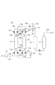
図1に示す第1実施形態に係るアルゴンガスの精製装置αは、例えば単結晶シリコン、多結晶シリコン鋳造炉のようなアルゴンガス供給源1から供給される使用済アルゴンガスを、回収して再利用できるように精製する。精製装置αは、フィルター2、活性炭吸着塔3、加熱器4、第1反応器5aと第2反応器5bを有する反応装置5、冷却器6、吸着装置7、酸素供給器8、一酸化炭素供給器9および製品タンクTを備える。
The argon gas purification apparatus α according to the first embodiment shown in FIG. 1 recovers and reuses spent argon gas supplied from an argon
精製前のアルゴンガスに含有される微量の不純物は、少なくとも酸素、水素、一酸化炭素、炭化水素、油分および窒素とされるが、二酸化炭素、水等の他の不純物を含有していてもよい。精製前のアルゴンガスにおける不純物の濃度は特に限定されず、例えば5モルppm〜80000モルppm程度とされる。 The trace amount of impurities contained in the argon gas before purification is at least oxygen, hydrogen, carbon monoxide, hydrocarbons, oil and nitrogen, but may contain other impurities such as carbon dioxide and water. . The concentration of impurities in the argon gas before purification is not particularly limited, and is, for example, about 5 mol ppm to 80000 mol ppm.
供給源1から供給されるアルゴンガスは、例えば油回転真空ポンプ(図示省略)により回収され、フィルター2(例えばCKD社製AF1000P )によって除塵された後に、先ず活性炭吸着塔3に導入される。活性炭吸着塔3に、アルゴンガスにおける炭化水素の一部と油分を吸着する活性炭が収容される。
Argon gas supplied from the
炭化水素の一部と油分が活性炭に吸着された後のアルゴンガスにおける酸素量が、そのアルゴンガスにおける水素、一酸化炭素、および炭化水素の全てと反応するのに必要な酸素の設定量を超えるか否かが判定される。その酸素の設定量は、本実施形態では、そのアルゴンガスにおける水素、一酸化炭素、および炭化水素の全てと反応するのに必要な酸素の化学量論量とされる。
アルゴンガスに含有される炭化水素の種類に応じて炭化水素を完全燃焼させるのに必要な酸素量は異なることから、上記判定はアルゴンガスに含有される不純物の組成と濃度を予め実験により求めた上で行うのが好ましい。例えば、アルゴンガスに含有される炭化水素がメタンである場合、アルゴンガスにおける水素、一酸化炭素、およびメタンが酸素と反応して水と二酸化炭素を生成する反応式は以下の通りである。
H2 +1/2 O2 →H2 O
CO+1/2 O2 →CO2
CH4 +2O2 →CO2 +2H2 O
この場合、アルゴンガスにおける酸素モル濃度が水素モル濃度の1/2と一酸化炭素モル濃度の1/2とメタンモル濃度の2倍との和に等しい値を超えるか否かにより、アルゴンガスにおける酸素量が上記化学量論量を超えるか否かを判定すればよい。もちろん、アルゴンガスに含有される炭化水素はメタンに限定されるものではなく、また、2種類以上の炭化水素が含有されていてもよい。
その酸素の設定量は、上記化学量論量である必要はなく、上記化学量論量以上であればよい。例えば、上記化学量論量の1.05倍〜2.0倍の値にするのが好ましく、1.05倍以上とすることでアルゴンガスにおける酸素を水素、一酸化炭素、および炭化水素と確実に反応させることができ、2.0倍以下とすることで酸素濃度が必要以上に高くなるのを防止できる。
The amount of oxygen in the argon gas after some of the hydrocarbons and oil are adsorbed on the activated carbon exceeds the set amount of oxygen required to react with all of the hydrogen, carbon monoxide, and hydrocarbons in the argon gas. It is determined whether or not. In this embodiment, the set amount of oxygen is the stoichiometric amount of oxygen necessary to react with all of hydrogen, carbon monoxide, and hydrocarbon in the argon gas.
Since the amount of oxygen required for complete combustion of the hydrocarbons differs depending on the type of hydrocarbons contained in the argon gas, the above determination was performed by previously determining the composition and concentration of the impurities contained in the argon gas. It is preferable to perform the above. For example, when the hydrocarbon contained in the argon gas is methane, the reaction formula in which hydrogen, carbon monoxide, and methane in the argon gas react with oxygen to produce water and carbon dioxide is as follows.
H 2 +1/2 O 2 → H 2 O
CO + 1/2 O 2 → CO 2
CH 4 + 2O 2 → CO 2 + 2H 2 O
In this case, the oxygen concentration in the argon gas depends on whether the oxygen molar concentration in the argon gas exceeds a value equal to the sum of 1/2 the hydrogen molar concentration, 1/2 the carbon monoxide molar concentration and twice the methane molar concentration. What is necessary is just to determine whether the quantity exceeds the said stoichiometric quantity. Of course, the hydrocarbon contained in the argon gas is not limited to methane, and two or more kinds of hydrocarbons may be contained.
The set amount of oxygen does not have to be the stoichiometric amount, and may be more than the stoichiometric amount. For example, the value is preferably 1.05 to 2.0 times the stoichiometric amount, and 1.05 times or more ensures that the oxygen in the argon gas is hydrogen, carbon monoxide, and hydrocarbon. The oxygen concentration can be prevented from becoming unnecessarily high by setting it to 2.0 times or less.
アルゴンガスにおける酸素量が上記設定量以下である場合、上記設定量を超えるようにアルゴンガスに酸素が添加される。アルゴンガスにおける酸素量が上記設定量を超える場合、酸素添加を行う必要はない。すなわち本実施形態の精製装置αは、アルゴンガスにおける酸素量が上記設定量を超える場合は、そのアルゴンガスを直接に精製し、また、その酸素量が上記設定量以下の場合は、その設定量を超えるように酸素が添加された後のアルゴンガスを精製する。第1反応器5aに導入されるアルゴンガスに酸素を添加可能な酸素供給器8を設けることで、アルゴンガスにおける酸素量が上記設定量以下である場合、上記設定量を超えるようにアルゴンガスに酸素を添加できる。
酸素供給器8は、例えば流量制御弁を有する高圧酸素容器のような、第1反応器5aへのアルゴンガスの導入流量に応じた流量で酸素を添加可能なものにより構成できる。なお、その酸素供給前に、第1反応器5aに導入されるアルゴンガスをサンプリングするためのサンプリングラインを設け、そのサンプリングラインに酸素分析計(例えばGEセンシング&インスペクション・テクノロジーズ(株)製DE―150ε)、水素分析ガスクロマトグラフィー(例えばGLscience社製PDD)、一酸化炭素分析計(例えば富士電機システムズ社製ZRE)および全炭化水素分析計(例えば堀場社製FIA−510)
を設け、また、第1反応器5aから流出して第2反応器5bに導入される前のアルゴンガスのサンプリングラインに酸素分析計を設けるのが好ましい。これにより、アルゴンガスにおける不純物組成を連続的に監視することで、より確実に微過剰の酸素を添加できる。
When the amount of oxygen in the argon gas is less than or equal to the set amount, oxygen is added to the argon gas so as to exceed the set amount. When the amount of oxygen in the argon gas exceeds the set amount, it is not necessary to add oxygen. That is, the purification apparatus α of the present embodiment directly purifies the argon gas when the oxygen amount in the argon gas exceeds the set amount, and the set amount when the oxygen amount is equal to or less than the set amount. The argon gas after the oxygen is added so as to exceed is purified. By providing the oxygen supply device 8 capable of adding oxygen to the argon gas introduced into the
The oxygen supply device 8 can be constituted by a device capable of adding oxygen at a flow rate corresponding to the flow rate of argon gas introduced into the
It is preferable to provide an oxygen analyzer in the sampling line for argon gas before flowing out from the
活性炭吸着塔3から流出するアルゴンガスは加熱器4を介して第1反応器5aに導入される。加熱器4によるアルゴンガスの加熱温度は、第1反応器5aにおける反応を完結するためには200℃以上にするのが好ましく、触媒の寿命短縮を防止する観点から400℃以下とするのが好ましい。
Argon gas flowing out from the activated
第1反応器5a内でアルゴンガスにおける一酸化炭素、水素、および炭化水素と酸素とが反応することで、酸素が残留された状態で二酸化炭素と水が生成されるように、第1反応器5aに触媒が収容される。第1反応器5aに収容される触媒は、酸素を一酸化炭素、水素、および炭化水素と反応させるものであれば特に限定されない。例えば、白金、白金合金、パラジウム、ルテニウム、又はこれらの混合物等を、アルミナに担持した触媒を用いることができる。アルゴンガスがメタンのような低級炭化水素を多く含む場合、十分に反応が進行するように反応温度を300℃以上にするのが好ましい。よって、耐熱性が良く、反応性の高いパラジウムをアルミナに担持した触媒を用いるのが好ましい。そのようなパラジウム触媒を用いることで、アルゴンガスにおける炭化水素を第1反応器5aにおいて効果的に低減できる。
The first reactor is configured such that carbon monoxide, hydrogen, and hydrocarbons in the argon gas react with oxygen in the
第1反応器5aから流出するアルゴンガスは第2反応器5bに導入される。一酸化炭素供給器9により、第1反応器5aから流出後に第2反応器5bに導入されるアルゴンガスに一酸化炭素が添加され、アルゴンガスと共に第2反応器5bに導入される。この一酸化炭素の添加により、第2反応器5bに導入されるアルゴンガスにおける一酸化炭素量が、そのアルゴンガスにおける残留された酸素の全てと反応するのに必要な設定量を超えるものとされる。
その一酸化炭素の設定量は、本実施形態では、そのアルゴンガスにおける酸素の全てと反応するのに必要な一酸化炭素の化学量論量とされる。この場合、アルゴンガスにおける一酸化炭素モル濃度が、第1反応器5a出口で計測される酸素モル濃度の2倍を超えることにより、アルゴンガスにおける一酸化炭素量が上記化学量論量を超える。
その一酸化炭素の設定量は、上記化学量論量である必要はなく、上記化学量論量以上であればよい。例えば、上記化学量論量の1.05倍〜2.0倍の値にするのが好ましく、1.05倍以上とすることでアルゴンガスにおける一酸化炭素を残留酸素と確実に反応させて残留酸素を消費でき、2.0倍以下とすることで残留する一酸化炭素濃度が必要以上に高くなるのを防止できる。
一酸化炭素供給器9は、例えば流量制御弁を有する高圧一酸化炭素容器のような、第2反応器5bへのアルゴンガスの導入流量に応じた流量で一酸化炭素を添加可能なものにより構成できる。なお、その一酸化炭素の供給前に、第2反応器5bに導入されるアルゴンガスをサンプリングするためのサンプリングラインを設け、そのサンプリングラインに酸素分析計および一酸化炭素分析計を設け、また、第2反応器5bから流出して吸着装置7に導入される前のアルゴンガスのサンプリングラインに一酸化炭素分析計を設けるのが好ましい。これにより、アルゴンガスにおける不純物組成を連続的に監視することで、より確実に微過剰の一酸化炭素を添加できる。
Argon gas flowing out from the
In this embodiment, the set amount of carbon monoxide is the stoichiometric amount of carbon monoxide necessary to react with all of the oxygen in the argon gas. In this case, the carbon monoxide molar concentration in the argon gas exceeds twice the oxygen molar concentration measured at the outlet of the
The set amount of the carbon monoxide does not need to be the stoichiometric amount, and may be more than the stoichiometric amount. For example, the value is preferably 1.05 to 2.0 times the stoichiometric amount, and by making the value 1.05 times or more, the carbon monoxide in the argon gas is reliably reacted with the residual oxygen to remain. Oxygen can be consumed, and by making it 2.0 times or less, it is possible to prevent the residual carbon monoxide concentration from becoming higher than necessary.
The
第2反応器5b内でアルゴンガスにおける酸素と一酸化炭素とが反応することで、一酸化炭素が残留された状態で二酸化炭素が生成されるように、第2反応器5bにルテニウム触媒、パラジウム触媒、又はこれらの混合触媒が収容される。そのルテニウム触媒、パラジウム触媒、又はこれらの混合触媒を、アルミナに担持するのが好ましい。また、反応温度は80℃以上、200℃以下にするのが好ましい。80℃未満では反応性が低下し、200℃を超える温度にしても見合った効果は得られずエネルギー的に不利である。
In the
第2反応器5bから流出するアルゴンガスは、冷却器6によって冷却され、水分を低減された後に吸着装置7に到る。本実施形態の吸着装置7はPSAユニット10とTSAユニット20を有する。
The argon gas flowing out from the
PSAユニット10は、アルゴンガスにおける少なくとも一酸化炭素、二酸化炭素、水、および窒素を、常温での圧力スイング吸着法により吸着剤に吸着する。冷却器6によって冷却されたアルゴンガスはPSAユニット10に導入される。これにより、第1反応器5aにおいて生成された二酸化炭素と水、および、第2反応器5bにおいて生成された二酸化炭素と残留する一酸化炭素が、アルゴンガスに当初から含有されていた窒素と共にPSAユニット10において吸着剤に吸着される。また、PSAユニット10に導入されるアルゴンガスに炭化水素が残留する場合、その炭化水素を吸着することもできる。
The
PSAユニット10は公知のものを用いることができる。例えば図2に示すPSAユニット10は2塔式であり、アルゴンガスを圧縮する圧縮機12と、第1、第2吸着塔13を有し、各吸着塔13に吸着剤が充填されている。その吸着剤は、一酸化炭素、二酸化炭素、水、および窒素を吸着できるものとされ、本実施形態では窒素吸着効果を高めるためにX型ゼオライトが用いられ、特にLi−X型、Ca−X型の合成ゼオライトが好ましい。また、各吸着塔13の下部に脱水のためのアルミナを、水分吸着効果を高める吸着剤として充填してもよい。
吸着塔13の入口13aそれぞれは、切替バルブ13bを介して原料配管13fに接続され、切替バルブ13cおよびサイレンサー13eを介して大気中に接続され、切替バルブ13dと下部均圧配管13gを介して互いに接続される。第2反応器5bから流出して冷却器6によって冷却されたアルゴンガスは、圧縮機12により圧縮された後に原料配管13fに到る。
吸着塔13の出口13kそれぞれは、切替バルブ13lを介して流出配管13oに接続され、切替バルブ13mを介して洗浄配管13pに接続され、切替バルブ13nと上部均圧配管13qを介して互いに接続される。
流出配管13oは、並列配置された逆止弁13rと切替バルブ13sを介して均圧槽14の入口に接続される。均圧槽14の出口は、吸着塔13における吸着圧力を制御するための圧力調節バルブ14aを介して貯留槽15の入口に接続される。貯留槽15の出口は、出口配管15aを介してTSAユニット20に接続される。また、流出配管13oと均圧槽14は、流量制御バルブ13u、流量指示調節計13vを介して洗浄配管13pに接続され、吸着塔13から流出した不純物濃度の低減されたアルゴンガスを、洗浄配管13pを介して吸着塔13に一定流量に調節して再び送ることが可能とされている。
As the
Each of the
Each of the
The outflow pipe 13o is connected to the inlet of the
PSAユニット10の第1、第2吸着塔13それぞれにおいて、吸着工程、均圧工程、脱着工程、洗浄工程、均圧工程、昇圧工程が順次行われる。
すなわち、第1吸着塔13において切替バルブ13b、13lのみが開かれることで、圧縮機12により圧縮されたアルゴンガスが、切替バルブ13bを介して第1吸着塔13に導入される。その導入されたアルゴンガス中の少なくとも一酸化炭素、二酸化炭素、窒素、水分が吸着剤に吸着されることで、第1吸着塔13においては吸着工程が行われる。第1吸着塔13において不純物の含有率が低減されたアルゴンガスは、流出配管13oを介して均圧槽14に送られる。この際、第2吸着塔13において、切替バルブ13m、13cのみが開かれることで、第1吸着塔13から流出配管13oに送られたアルゴンガスの一部が、洗浄配管13p、流量制御バルブ13uを介して第2吸着塔13に送られ、第2吸着塔13においては洗浄工程が行われる。
次に、第1吸着塔13において切替バルブ13b、13lが閉じられ、第2吸着塔13において切替バルブ13m、13cが閉じられ、切替バルブ13n、13dが開かれることで、第1吸着塔13と第2吸着塔13において内部圧力の均一化を図る均圧工程が行われる。
次に、切替バルブ13n、13dが閉じられ、第1吸着塔13において切替バルブ13cが開かれることで、吸着剤から不純物を脱着する脱着工程が第1吸着塔13において行われ、脱着された不純物はガスと共にサイレンサー13eを介して大気中に放出される。この際、第2吸着塔13において切替バルブ13b、13lが開かれ、切替バルブ13sが開かれることで、圧縮機12により圧縮されたアルゴンガスが切替バルブ13bを介して、均圧槽14における不純物の含有率が低減されたアルゴンガスが切替バルブ13sと切替バルブ13lを介して導入され、第2吸着塔13において昇圧工程が行われると共に吸着工程が開始される。
次に、第1吸着塔13において切替バルブ13mが開かれ、切替バルブ13sが閉じられ、これにより、吸着工程が行われている第2吸着塔13から流出配管13oに送られたアルゴンガスの一部が、洗浄配管13p、流量制御バルブ13uを介して第1吸着塔13に送られ、第1吸着塔13において洗浄工程が行われる。洗浄工程で用いられたガスは、切替バルブ13c、サイレンサー13eを介して大気中に放出される。
次に、第1吸着塔13において切替バルブ13c、13mが閉じられ、第2吸着塔13において切替バルブ13b、13lが閉じられ、切替バルブ13n、13dが開かれることで、第1吸着塔13と第2吸着塔13において内部圧力の均一化を図る均圧工程が行われる。
次に、切替バルブ13n、13dが閉じられ、第1吸着塔13において切替バルブ13b、13lが開かれ、切替バルブ13sが開かれることで、圧縮機12により圧縮されたアルゴンガスと均圧槽14における不純物の含有率が低減されたアルゴンガスが導入され、第1吸着塔13において昇圧工程が行われると共に吸着工程が開始される。この際、第2吸着塔13において切替バルブ13cが開かれることで、吸着剤から不純物を脱着する脱着工程が第2吸着塔13において行われ、不純物はガスと共にサイレンサー13eを介して大気中に放出される。
上記の各工程が第1、第2吸着塔13それぞれにおいて順次繰り返されることで、不純物含有率を低減されたアルゴンガスが均圧槽14、圧力調節バルブ14a、貯留槽15、出口配管15aを介してTSAユニット20に送られる。
なお、PSAユニット10は図2に示すものに限定されず、例えば塔数は2以外、例えば3でも4でもよい。
In each of the first and second adsorption towers 13 of the
That is, by opening only the switching
Next, the switching
Next, when the switching
Next, the switching
Next, the switching
Next, the switching
The above steps are sequentially repeated in the first and second adsorption towers 13, respectively, so that the argon gas whose impurity content has been reduced passes through the
Note that the
PSAユニット10において吸着剤に吸着されなかった窒素を含むアルゴンガスがTSAユニット20に導入される。TSAユニット20は、アルゴンガスにおける窒素を、−10℃〜−50℃でのサーマルスイング吸着法により吸着剤に吸着する。
Argon gas containing nitrogen that has not been adsorbed by the adsorbent in the
TSAユニット20は公知のものを用いることができる。例えば図3に示すTSAユニット20は2塔式であり、PSAユニット10から送られてくるアルゴンガスを予冷する熱交換型予冷器21と、予冷器21により冷却されたアルゴンガスを更に冷却する熱交換型冷却器22と、第1、第2吸着塔23、各吸着塔23を覆う熱交換部24を有する。熱交換部24は、吸着工程時には冷媒で吸着剤を冷却し、脱着工程時には熱媒で吸着剤を加熱する。各吸着塔23は、吸着剤が充填された多数の内管を有する。その吸着剤としては窒素の吸着に適したものが用いられ、例えばカルシウム(Ca)またはリチウム(Li)でイオン交換されたゼオライト系吸着剤を用いるのが好ましく、さらに、イオン交換率70%以上とするのが特に好ましく、比表面積600m2 以上とするのが特に好ましい。
冷却器22は、各吸着塔23の入口23aに切替バルブ23bを介して接続される。
吸着塔23の入口23aそれぞれは、切替バルブ23cを介して大気中に通じる。
吸着塔23の出口23eそれぞれは、切替バルブ23fを介して流出配管23gに接続され、切替バルブ23hを介して冷却・昇圧用配管23iに接続され、切替バルブ23jを介して洗浄用配管23kに接続される。
流出配管23gは予冷器21の一部を構成し、流出配管23gから流出する精製されたアルゴンガスによりPSAユニット10から送られてくるアルゴンガスが冷却される。流出配管23gから精製されたアルゴンガスが切替バルブ23lを介し流出される。
冷却・昇圧用配管23i、洗浄用配管23kは、流量計23m、流量制御バルブ23o、切替バルブ23nを介して流出配管23gに接続される。
熱交換部24は多管式とされ、吸着塔23を構成する多数の内管を囲む外管24a、冷媒供給源24b、冷媒用ラジエタ24c、熱媒供給源24d、熱媒用ラジエタ24eで構成される。また、冷媒供給源24bから供給される冷媒を外管24a、冷媒用ラジエタ24cを介して循環させる状態と、熱媒供給源24dから供給される熱媒を外管24a、熱媒用ラジエタ24eを介して循環させる状態とに切り換えるための複数の切替バルブ24fが設けられている。さらに、冷媒用ラジエタ24cから分岐する配管により冷却器22の一部が構成され、冷媒供給源24bから供給される冷媒によりアルゴンガスが冷却器22において冷却され、その冷媒はタンク24gに還流される。
A known
The cooler 22 is connected to the
Each of the
Each of the
The
The cooling / pressurizing piping 23i and the cleaning
The
TSAユニット20の第1、第2吸着塔23それぞれにおいて、吸着工程、脱着工程、洗浄工程、冷却工程、昇圧工程が順次行われる。
すなわち、TSAユニット20において、PSAユニット10から供給されるアルゴンガスは予冷器21、冷却器22において冷却された後に、切替バルブ23bを介して第1吸着塔23に導入される。この際、第1吸着塔23は熱交換機24において冷媒が循環することで−10℃〜−50℃に冷却される状態とされ、切替バルブ23c、23h、23jは閉じられ、切替バルブ23fは開かれ、アルゴンガスに含有される少なくとも窒素は吸着剤に吸着される。これにより、第1吸着塔23において吸着工程が行われ、不純物の含有率が低減された精製アルゴンガスが吸着塔23から切替バルブ23lを介して流出され、製品タンクTに送られる。
第1吸着塔23において吸着工程が行われている間に、第2吸着塔23において脱着工程、洗浄工程、冷却工程、昇圧工程が進行する。
すなわち第2吸着塔23においては、吸着工程が終了した後、脱着工程を実施するため、切替バルブ23b、23fが閉じられ、切替バルブ23cが開かれる。これにより第2吸着塔23においては、不純物を含んだアルゴンガスが大気中に放出され、圧力がほぼ大気圧まで低下される。この脱着工程においては、第2吸着塔23で吸着工程時に冷媒を循環させていた熱交換部24の切替バルブ24fを閉状態に切り替えて冷媒の循環を停止させ、冷媒を熱交換部24から抜き出して冷媒供給源24bに戻す切替バルブ24fを開状態に切り替える。
次に、第2吸着塔23において洗浄工程を実施するため、第2吸着塔23の切替バルブ23c、23jと洗浄用配管23kの切替バルブ23nが開状態とされ、熱交換型予冷器21における熱交換により加熱された精製アルゴンガスの一部が、洗浄用配管23kを介して第2吸着塔23に導入される。これにより第2吸着塔23においては、吸着剤からの不純物の脱着と精製アルゴンガスによる洗浄が実施され、その洗浄に用いられたアルゴンガスは切替バルブ23cから不純物と共に大気中に放出される。この洗浄工程においては、第2吸着塔23で熱媒を循環させるための熱交換部24の切替バルブ24fを開状態に切り替える。
次に、第2吸着塔23において冷却工程を実施するため、第2吸着塔23の切替バルブ23jと洗浄用配管23kの切替バルブ23nが閉状態とされ、第2吸着塔23の切替バルブ23hと冷却・昇圧用配管23iの切替バルブ23nが開状態とされ、第1吸着塔23から流出する精製アルゴンガスの一部が冷却・昇圧用配管23iを介して第2吸着塔23に導入される。これにより、第2吸着塔23内を冷却した精製アルゴンガスは切替バルブ23cを介して大気中に放出される。この冷却工程においては、熱媒を循環させるための切替バルブ24fを閉じ状態に切り替えて熱媒循環を停止させ、熱媒を熱交換部24から抜き出して熱媒供給源24dに戻す切替バルブ24fを開状態に切り替える。熱媒の抜き出しの終了後に、第2吸着塔23で冷媒を循環させるための熱交換部24の切替バルブ24fを開状態に切り替え、冷媒循環状態とする。この冷媒循環状態は、次の昇圧工程、それに続く吸着工程の終了まで継続する。
次に、第2吸着塔23において昇圧工程を実施するため、第2吸着塔23の切替バルブ23cが閉じられ、第1吸着塔23から流出する精製アルゴンガスの一部が導入されることで第2吸着塔23の内部が昇圧される。この昇圧工程は、第2吸着塔23の内圧が第1吸着塔23の内圧とほぼ等しくなるまで継続される。昇圧工程が終了すれば、第2吸着塔23の切替バルブ23hと冷却・昇圧用配管23iの切替バルブ23nが閉じられ、これによって第2吸着塔23の全ての切替バルブ23b、23c、23f、23h、23jが閉じた状態となり、第2吸着塔23は次の吸着工程まで待機状態になる。
第2吸着塔23の吸着工程は第1吸着塔23の吸着工程と同様に実施される。第2吸着塔23において吸着工程が行われている間に、第1吸着塔23において脱着工程、洗浄工程、冷却工程、昇圧工程が第2吸着塔23におけると同様に進行される。
なお、TSAユニット20は図3に示すものに限定されず、例えば塔数は2以上、例えば3でも4でもよい。
In each of the first and second adsorption towers 23 of the
That is, in the
While the adsorption process is performed in the
That is, in the
Next, in order to carry out the cleaning process in the
Next, in order to perform the cooling process in the
Next, in order to perform the pressure increasing process in the
The adsorption process of the
The
図4、図5は、本発明の第2実施形態に係るアルゴンガスの精製装置αを示す。第2実施形態における第1実施形態との相違点は吸着装置7の構成にある。すなわち、図4に示すように第2実施形態の吸着装置7はPSAユニット10′を備えるがTSAユニットは備えていない。PSAユニット10′は、アルゴンガスにおける少なくとも一酸化炭素、二酸化炭素、水、および窒素を、常温での圧力スイング吸着法により吸着剤に吸着する。冷却器6によって冷却されたアルゴンガスはPSAユニット10′に導入される。これにより、第1反応器5aにおいて生成された二酸化炭素と水、および、第2反応器5bにおいて生成された二酸化炭素と残留する一酸化炭素が、アルゴンガスに当初から含有されていた窒素と共にPSAユニット10′において吸着剤に吸着される。また、PSAユニット10′に導入されるアルゴンガスに炭化水素が残留する場合、その炭化水素を吸着することもできる。第2実施形態のPSAユニット10′は第1実施形態のPSAユニット10とは異なる構成を有する。
4 and 5 show an argon gas purification apparatus α according to a second embodiment of the present invention. The difference of the second embodiment from the first embodiment is the configuration of the adsorption device 7. That is, as shown in FIG. 4, the adsorption device 7 of the second embodiment includes a PSA unit 10 'but does not include a TSA unit. The PSA unit 10 'adsorbs at least carbon monoxide, carbon dioxide, water, and nitrogen in argon gas to the adsorbent by a pressure swing adsorption method at room temperature. The argon gas cooled by the
PSAユニット10′は公知のものを用いることができる。例えば図5に示すPSAユニット10′は4塔式であり、第2反応器5bから流出するアルゴンガスを圧縮する圧縮機12′と、4つの第1〜第4吸着塔13′を有し、各吸着塔13′に吸着剤が充填されている。その吸着剤は、一酸化炭素、二酸化炭素、水、および窒素を吸着できるものとされ、本実施形態では活性アルミナとX型ゼオライトとが用いられ、X型ゼオライトとしてはLi−X型やCa−X型の合成ゼオライトが好ましい。活性アルミナとX型ゼオライトの各吸着塔13′における配置は特に限定されず、例えば層状にして交互に配置してもよい。活性アルミナとX型ゼオライトとの重量比は5/95〜30/70にするのが好ましい。2層状にして交互に配置する場合、アルゴンガスの流れの上流に活性アルミナを配置し、下流にX型ゼオライトを配置するのが好ましい。
圧縮機12′は、各吸着塔13′の入口13a′に切替バルブ13b′を介して接続される。
吸着塔13′の入口13a′それぞれは、切替バルブ13e′およびサイレンサー13f′を介して大気中に接続される。
吸着塔13′の出口13k′それぞれは、切替バルブ13l′を介して流出配管13m′に接続され、切替バルブ13n′を介して昇圧配管13o′に接続され、切替バルブ13p′を介して均圧・洗浄出側配管13q′に接続され、切替バルブ13r′を介して均圧・洗浄入側配管13s′に接続される。
流出配管13m′は、圧力調節バルブ13t′を介して製品タンクTに接続される。
昇圧配管13o′は、流量制御バルブ13u′、流量指示調節計13v′を介して流出配管13m′に接続され、昇圧配管13o′での流量が一定に調節されることにより、製品タンクTに導入されるアルゴンガスの流量変動が防止される。
均圧・洗浄出側配管13q′と均圧・洗浄入側配管13s′は、一対の連結配管13w′を介して互いに接続され、各連結配管13w′に切替バルブ13x′が設けられている。
A known PSA unit 10 'can be used. For example, the
The compressor 12 'is connected to the
Each
Each of the
The
The booster pipe 13o ′ is connected to the
The pressure equalizing / cleaning
PSAユニット10′の第1〜第4吸着塔13′それぞれにおいて、吸着工程、減圧I工程(洗浄ガス出工程)、減圧II工程(均圧ガス出工程)、脱着工程、洗浄工程(洗浄ガス入工程)、昇圧I工程(均圧ガス入工程)、昇圧II工程が順次行われる。第1吸着塔13′を基準に各工程を以下の通り説明する。
すなわち、第1吸着塔13′において切替バルブ13b′と切替バルブ13l′のみが開かれ、第2反応器5bから供給されるアルゴンガスは圧縮機12′から切替バルブ13b′を介して第1吸着塔13′に導入される。これにより、第1吸着塔13′において導入されたアルゴンガス中の少なくとも窒素、一酸化炭素、二酸化炭素および水分が吸着剤に吸着されることで吸着工程が行われ、不純物の含有率が低減されたアルゴンガスが第1吸着塔13′から流出配管13m′を介して製品タンクTに送られる。この際、流出配管13m′に送られたアルゴンガスの一部は、昇圧配管13o′、流量制御バルブ13u′を介して別の吸着塔(本実施形態では第2吸着塔13′)に送られ、第2吸着塔13′において昇圧II工程が行われる。
次に、第1吸着塔13′の切替バルブ13b′、13l′を閉じ、切替バルブ13p′を開き、別の吸着塔(本実施形態では第4吸着塔13′)の切替バルブ13r′を開き、切替バルブ13x′の中の1つを開く。これにより、第1吸着塔13′の上部の比較的不純物含有率の少ないアルゴンガスが、均圧・洗浄入側配管13s′を介して第4吸着塔13′に送られ、第1吸着塔13′において減圧I工程が行われる。この際、第4吸着塔13′においては切替バルブ13e′が開かれ、洗浄工程が行われる。
次に、第1吸着塔13′の切替バルブ13p′と第4吸着塔13′の切替バルブ13r′を開いたまま、第4吸着塔13′の切替バルブ13e′を閉じる。これにより、第1吸着塔13′と第4吸着塔13′の内部圧力が均一、またはほぼ均一になるまで第4吸着塔13′にガスの回収を実施する減圧II工程が行われる。この際、切替バルブ13x′は場合に応じ2つとも開いてもよい。
次に、第1吸着塔13′の切替バルブ13e′を開き、切替バルブ13p′を閉じることにより、吸着剤から不純物を脱着する脱着工程が行われ、不純物はガスと共にサイレンサー13f′を介して大気中に放出される。
次に、第1吸着塔13′の切替バルブ13r′を開き、吸着工程を終わった状態の第2吸着塔13′の切替バルブ13b′、13l′を閉じ、切替バルブ13p′を開く。これにより、第2吸着塔13′の上部の比較的不純物含有率の少ないアルゴンガスが、均圧・洗浄入側配管13s′を介して第1吸着塔13′に送られ、第1吸着塔13′において洗浄工程が行われる。第1吸着塔13′において洗浄工程で用いられたガスは、切替バルブ13e′、サイレンサー13f′を介して大気中に放出される。この際、第2吸着塔13′では減圧I工程が行われる。
次に第2吸着塔13′の切替バルブ13p′と第1吸着塔13′の切替バルブ13r′を開いたまま、第1吸着塔13′の切替バルブ13e′を閉じることで昇圧I工程が行われる。この際、切替バルブ13x′は場合に応じ2つとも開いてもよい。
しかる後に、第1吸着塔13′の切替バルブ13r′を閉じる。これにより、一旦は工程の無い待機状態になる。この状態は、第4吸着塔13′の昇圧II工程が完了するまで持続する。第4吸着塔13′の昇圧が完了し、吸着工程が第3吸着塔13′から第4吸着塔13′に切り替わると、第1吸着塔の切替バルブ13n′を開く。これにより、吸着工程にある別の吸着塔(本実施形態では第4吸着塔13′)から流出配管13m′に送られたアルゴンガスの一部が、昇圧配管13o′、流量制御バルブ13u′を介して第1吸着塔13′に送られることで、第1吸着塔13′において昇圧II工程が行われる。
上記の各工程が第1〜第4吸着塔13′それぞれにおいて順次繰り返されることで、不純物含有率を低減されたアルゴンガスが製品タンクTに連続して送られる。
なお、PSAユニット10′は図5に示すものに限定されず、例えば塔数は4以外、例えば2でも3でもよい。
第2実施形態における他の構成は第1実施形態と同様である。
In each of the first to fourth adsorption towers 13 ′ of the
That is, only the switching
Next, the switching
Next, the switching
Next, a desorption process for desorbing impurities from the adsorbent is performed by opening the switching
Next, the switching
Next, while the switching
Thereafter, the switching
The above steps are sequentially repeated in each of the first to fourth adsorption towers 13 ′, whereby argon gas with a reduced impurity content is continuously sent to the product tank T.
The PSA unit 10 'is not limited to that shown in FIG. 5, and the number of towers may be other than 4, for example, 2 or 3.
Other configurations in the second embodiment are the same as those in the first embodiment.
上記第1実施形態および第2実施形態の精製装置αによれば、少なくとも酸素、水素、一酸化炭素、炭化水素、油分および窒素を不純物として含有するアルゴンガスを回収して精製する際に、アルゴンガスに含有される油分を活性炭により吸着し、さらに、油分に由来する炭化水素の一部も活性炭により吸着でき、特に炭素数が1 〜5以外の炭化水素を活性炭により効果的に吸着できる。次に、アルゴンガスにおける酸素量が、アルゴンガスにおける水素、一酸化炭素、および炭化水素の全てと反応するのに必要な酸素の設定量を超えるか否かを判定し、その酸素量が前記設定量以下である場合は設定量を超えるように酸素を添加する。しかる後に、アルゴンガスにおける一酸化炭素、水素、および炭化水素と酸素とを触媒を用いて反応させることで、酸素を残留させた状態で二酸化炭素と水を生成できる。これにより、アルゴンガスにおける主な不純物は二酸化炭素、水、酸素、および窒素とされる。次に、アルゴンガスにおける一酸化炭素量が、その残留された酸素の全てと反応するのに必要な設定量を超えるように、一酸化炭素を添加する。しかる後に、アルゴンガスにおける酸素と一酸化炭素とをルテニウム触媒、パラジウム触媒又はこれらの混合触媒を用いて反応させることで、一酸化炭素が残留された状態で二酸化炭素を生成できる。これにより、アルゴンガス中の主な不純物は水、一酸化炭素、二酸化炭素および窒素とされる。ここで、アルゴンガスにおける酸素と一酸化炭素とを反応させる触媒としてルテニウム触媒、パラジウム触媒、又はこれらの混合触媒を用いることで、水と一酸化炭素との反応により水素が生じるのを防止できる。次に、アルゴンガスにおける一酸化炭素、二酸化炭素、水、および窒素を、圧力スイング吸着法により吸着剤に吸着させることができる。
すなわち、油分と炭素数が1 〜5以外の炭化水素を活性炭により効果的に吸着することにより、アルゴンガスにおける炭化水素量を低減し、これにより、後の炭化水素と酸素との反応により生成される水と二酸化炭素の量を低減すると共に、後の吸着装置7における吸着負荷を軽減できる。また、吸着装置7による吸着処理では除去困難な水素がアルゴンガスに残留するのを防止できるので、アルゴンガスを高純度に精製することが可能になる。さらに、吸着装置7による吸着処理の前処理段階においてアルゴンガスから酸素を除去できるので、精製負荷を低減できる。また、圧力スイング吸着法のために用いる吸着剤としてX型ゼオライトを用いることで、一酸化炭素、二酸化炭素、水、および窒素だけでなく炭化水素の吸着効果が高くなる。よって、吸着装置7による吸着処理の前段階でアルゴンガスに炭化水素が残留したとしても、圧力スイング吸着法によりアルゴンガスにおける炭化水素を吸着剤に効果的に吸着させることができる。
According to the purification apparatus α of the first embodiment and the second embodiment, when the argon gas containing at least oxygen, hydrogen, carbon monoxide, hydrocarbon, oil, and nitrogen as impurities is recovered and purified, The oil contained in the gas can be adsorbed by activated carbon, and some of the hydrocarbons derived from the oil can also be adsorbed by activated carbon, and in particular, hydrocarbons other than those having 1 to 5 carbon atoms can be effectively adsorbed by activated carbon. Next, it is determined whether or not the amount of oxygen in the argon gas exceeds the set amount of oxygen necessary to react with all of hydrogen, carbon monoxide, and hydrocarbons in the argon gas, and the amount of oxygen is determined as described above. When the amount is less than the amount, oxygen is added so as to exceed the set amount. Thereafter, carbon monoxide, hydrogen, and hydrocarbon in argon gas are reacted with oxygen using a catalyst, so that carbon dioxide and water can be generated with oxygen remaining. Thereby, main impurities in the argon gas are carbon dioxide, water, oxygen, and nitrogen. Next, carbon monoxide is added so that the amount of carbon monoxide in the argon gas exceeds the set amount necessary to react with all of the remaining oxygen. Thereafter, oxygen and carbon monoxide in the argon gas are reacted with each other using a ruthenium catalyst, a palladium catalyst, or a mixed catalyst thereof, whereby carbon dioxide can be generated with carbon monoxide remaining. Thereby, main impurities in the argon gas are water, carbon monoxide, carbon dioxide, and nitrogen. Here, by using a ruthenium catalyst, a palladium catalyst, or a mixed catalyst thereof as a catalyst for reacting oxygen and carbon monoxide in argon gas, hydrogen can be prevented from being generated due to the reaction between water and carbon monoxide. Next, carbon monoxide, carbon dioxide, water, and nitrogen in the argon gas can be adsorbed on the adsorbent by the pressure swing adsorption method.
That is, by effectively adsorbing hydrocarbons having an oil content and a carbon number other than 1 to 5 with activated carbon, the amount of hydrocarbons in the argon gas is reduced, and thus produced by the subsequent reaction between hydrocarbons and oxygen. It is possible to reduce the amount of water and carbon dioxide and to reduce the adsorption load in the subsequent adsorption device 7. Further, since it is possible to prevent hydrogen that is difficult to be removed by the adsorption treatment by the adsorption device 7 from remaining in the argon gas, the argon gas can be purified with high purity. Furthermore, since oxygen can be removed from the argon gas in the pretreatment stage of the adsorption treatment by the adsorption device 7, the purification load can be reduced. Further, by using X-type zeolite as the adsorbent used for the pressure swing adsorption method, not only carbon monoxide, carbon dioxide, water, and nitrogen, but also a hydrocarbon adsorption effect is enhanced. Therefore, even if hydrocarbons remain in the argon gas in the previous stage of the adsorption process by the adsorption device 7, the hydrocarbons in the argon gas can be effectively adsorbed by the adsorbent by the pressure swing adsorption method.
上記第1実施形態の精製装置αによれば、圧力スイング吸着法による吸着の後に、アルゴンガスにおける窒素を、−10℃〜−50℃でのサーマルスイング吸着法により吸着剤に吸着させることができる。このようにサーマルスイング吸着法による吸着を併用することで、PSAユニット10の負荷を低減し、精製前のアルゴンガスにおける不純物濃度の変動に対応し、確実に不純物を除去できる。よって、精製後におけるアルゴンガスの純度をより高めることができる。また、サーマルスイング吸着法による吸着処理の前処理段階においてアルゴンガスから酸素を除去でき、さらに圧力スイング吸着法で一酸化炭素を除去できるので、サーマルスイング吸着法による吸着処理の際の冷却エネルギーを低減できる。さらに、サーマルスイング吸着法による吸着処理の前処理段階においてアルゴンガスから炭化水素を除去できるので、サーマルスイング吸着法のために用いる吸着剤の再生時に、窒素以外のものを吸着剤から脱離させる必要がなく、再生エネルギーを低減できる。しかも、PSAユニット10における吸着剤としてX型ゼオライトを用いることで窒素の吸着効果を高めることができるので、TSAユニット20における窒素の吸着負荷を低減し、回収されたアルゴンガスをより高純度に精製できる。
According to the purification apparatus α of the first embodiment, after adsorption by the pressure swing adsorption method, nitrogen in the argon gas can be adsorbed to the adsorbent by a thermal swing adsorption method at −10 ° C. to −50 ° C. . Thus, by using the adsorption by the thermal swing adsorption method together, the load on the
上記第2実施形態の精製装置αによれば、PSAユニット10′における吸着剤として活性アルミナとX型ゼオライトとを用いることで、アルゴンガスにおける水分および二酸化炭素の吸着および脱着を活性アルミナにより行い、X型ゼオライトによる一酸化炭素、窒素および炭化水素の吸着効果を高くできる。これにより、吸着装置7による吸着処理の前段階においてアルゴンガスに炭化水素が残留したとしても、PSAユニット10′を大型化することなく炭化水素を圧力スイング吸着法により吸着剤に効果的に吸着させることができる。しかも、圧力スイング吸着法による一酸化炭素と窒素の吸着効果を高くできるので、TSAユニットを用いることなく、アルゴンガスを低エネルギーで高純度に精製できる。
According to the purification apparatus α of the second embodiment, by using activated alumina and X-type zeolite as adsorbents in the PSA unit 10 ', moisture and carbon dioxide are adsorbed and desorbed in argon gas with activated alumina. The adsorption effect of carbon monoxide, nitrogen and hydrocarbons by the X-type zeolite can be enhanced. Thereby, even if hydrocarbons remain in the argon gas in the previous stage of the adsorption process by the adsorption device 7, the hydrocarbons are effectively adsorbed by the adsorbent by the pressure swing adsorption method without increasing the size of the
上記第1実施形態の精製装置αを用いてアルゴンガスの精製を行った。精製前のアルゴンガスは不純物として酸素を300モルppm、水素を30モルppm、一酸化炭素を200モルppm、窒素を1200モルppm、二酸化炭素を10モルppm、水分を10モルppm、炭化水素としてメタンを10モルppm、C2〜C5の炭化水素をC1の炭化水素換算で20モルppm、油分を5g/m3 それぞれ含有した。このアルゴンガスを標準状態で4.2L/minの流量で活性炭吸着塔3に導入した。活性炭吸着塔3は呼び径32Aのパイプ状とし、日本エンバイロケミカルズ製GX6/8成型炭を10L充填した。次に、アルゴンガスを第1反応器5aに導入した。第1反応器5aにおいては、アルミナ担持のパラジウム触媒(NEケムキャット製DASH−220D)を50mL充填し、反応条件は温度350℃、大気圧、空間速度5000/hとした。この場合、アルゴンガスにおいて酸素は、水素、一酸化炭素、および炭化水素と反応させるのに必要な理論値の約1.8倍含まれている。第1反応器5aから流出するアルゴンガスに一酸化炭素供給器9から一酸化炭素を1.0ml/minの流量で添加して第2反応器5bに導入した。この場合、アルゴンガスにおいて一酸化炭素は、残存酸素を消費するのに必要な理論値の約1.2倍含まれる。第2反応器5bにおいては、アルミナ担持のルテニウム触媒(スードケミー社製RUA)を50ml充填し、反応条件は温度150℃、大気圧、空間速度5000/ hとした。
第2反応器5bから流出するアルゴンガスを冷却し、その不純物含有率を吸着装置7により低減した。PSAユニット10は2塔式とし、各塔は呼び径32A、長さ1mのパイプ状とし、各塔に吸着剤としてLi−X型ゼオライト(東ソー製NSA−700)を充填した。PSAユニット10の操作条件は、吸着圧力0.8MPaG、脱着圧力10kPaG、サイクルタイム400sec/塔とし、均圧15secを実施した。TSAユニット20は2塔式とし、各塔に吸着剤としてCa−X型ゼオライト(水澤化学製812B)を1.25L充填し、吸着圧力は0.8MPaG、吸着温度は−35℃、脱着圧力は0.1MPaG、脱着温度は40℃とした。
この場合の第1反応器5aの出口、第2反応器5bの出口、PSAユニット10の出口、およびTSAユニット20の出口におけるアルゴンガスの不純物組成は、後記の表1に示す通りであった。表1における炭化水素の組成は、メタン濃度とC2〜C5炭化水素のC1炭化水素換算濃度との合計を示す。
また、活性炭吸着塔3の出口でのアルゴンガスの組成は以下の通りであった。
・活性炭吸着塔出口
水素:30モルppm、酸素:300モルppm、窒素:1200モルppm、一酸化炭素:200モルppm、二酸化炭素:10モルppm、メタン:10モルppm、C2〜C5炭化水素:C1炭化水素換算で15モルppm、水分:10モルppm、油分:未検出
なお、酸素濃度はDelta F 社製微量酸素濃度計型式DF−150Eにより測定し、一酸化炭素および二酸化炭素の濃度は島津製作所製GC-FIDを用いてメタナイザーを介して測定し、水素濃度についてはGLscience 社製GC-PDD により測定し、窒素濃度はラウンドサイエンス社製微量窒素分析計により測定し、炭化水素濃度は島津製作所製GC-FIDにより測定し、油分についてはCKD 製フィルタVFA1000のフィルタリングの増量からの計算により求め、水分は露点計を用いて測定した。
The argon gas was purified using the purification apparatus α of the first embodiment. Before purification, the argon gas contains 300 molppm of oxygen, 30 molppm of hydrogen, 200 molppm of carbon monoxide, 1200 molppm of nitrogen, 10 molppm of carbon dioxide, 10 molppm of water, and hydrocarbon as impurities. 10 mol ppm of methane, 20 mol ppm of C2-C5 hydrocarbon in terms of C1 hydrocarbon, and 5 g / m 3 of oil were contained. This argon gas was introduced into the activated
The argon gas flowing out from the
In this case, the impurity composition of the argon gas at the outlet of the
The composition of the argon gas at the outlet of the activated
Activated carbon adsorption tower outlet Hydrogen: 30 mol ppm, oxygen: 300 mol ppm, nitrogen: 1200 mol ppm, carbon monoxide: 200 mol ppm, carbon dioxide: 10 mol ppm, methane: 10 mol ppm, C2-C5 hydrocarbon:
精製に用いたアルゴンガスの酸素濃度が50モルppm、窒素濃度が200ppmであり、第1反応器5a前でアルゴンガスに酸素供給器8から酸素を1.1ml/minで添加した(これにより酸素は、水素、一酸化炭素、および炭化水素と反応させるのに必要な理論値の約1.4倍含まれる)。その他は実施例1と同じ条件でアルゴンガスを精製した。
この場合の活性炭吸着塔3の出口、およびTSAユニット20の出口でのアルゴンガスの不純物組成は以下の通りであった。
・活性炭吸着塔出口
水素:30モルppm、酸素:50モルppm、窒素:200モルppm、一酸化炭素:200モルppm、二酸化炭素:10モルppm、水分:10モルppm、メタン:10モルppm、C2〜C5炭化水素:C1炭化水素換算で15モルppm、油分:未検出。
・TSAユニット出口
水素:0.1モルppm未満、酸素:0.3モルppm、窒素:1モルppm未満、一酸化炭素:1モルppm未満、二酸化炭素:1モルppm未満、炭化水素:0.1モルppm未満、水分:1モルppm未満。
The oxygen concentration of the argon gas used for the purification was 50 mol ppm and the nitrogen concentration was 200 ppm, and oxygen was added to the argon gas from the oxygen supply device 8 at 1.1 ml / min before the
The impurity composition of argon gas at the outlet of the activated
Activated carbon adsorption tower outlet Hydrogen: 30 mol ppm, oxygen: 50 mol ppm, nitrogen: 200 mol ppm, carbon monoxide: 200 mol ppm, carbon dioxide: 10 mol ppm, moisture: 10 mol ppm, methane: 10 mol ppm, C2-C5 hydrocarbon: 15 mol ppm in terms of C1 hydrocarbon, oil: not detected.
-TSA unit outlet Hydrogen: Less than 0.1 mol ppm, Oxygen: 0.3 mol ppm, Nitrogen: less than 1 mol ppm, Carbon monoxide: less than 1 mol ppm, Carbon dioxide: less than 1 mol ppm, Hydrocarbon: 0.0. Less than 1 mol ppm, moisture: less than 1 mol ppm.
第2反応器5bにおいて用いる触媒をアルミナ担持のパラジウムとした。その他は実施例1と同じ条件でアルゴンガスを精製した。
この場合の第1反応器5aの出口、第2反応器5bの出口、PSAユニット10の出口、およびTSAユニット20の出口におけるアルゴンガスの不純物組成は、表1に示す通りであった。
The catalyst used in the
In this case, the impurity composition of argon gas at the outlet of the
第1反応器5aにおいて用いる触媒をアルミナ担持の白金(NEケムキャット製DASH−220)とした。その他は実施例1と同じ条件でアルゴンガスを精製した。
この場合の第1反応器5aの出口、第2反応器5bの出口、PSAユニット10の出口、およびTSAユニット20の出口におけるアルゴンガスの不純物組成は、表1に示す通りであった。
The catalyst used in the
In this case, the impurity composition of argon gas at the outlet of the
第2反応器5bにおいて用いる触媒をアルミナ担持の白金とした。その他は実施例1と同じ条件でアルゴンガスを精製した。
この場合の第1反応器5aの出口、第2反応器5bの出口、PSAユニット10の出口、およびTSAユニット20の出口におけるアルゴンガスの不純物組成は、表1に示す通りであった。
The catalyst used in the
In this case, the impurity composition of argon gas at the outlet of the

上記第2実施形態の精製装置αを用いてアルゴンガスの精製を行った。精製前のアルゴンガスは不純物として酸素を300モルppm、水素を30モルppm、一酸化炭素を200モルppm、窒素を1200モルppm、二酸化炭素を10モルppm、水分を10モルppm、炭化水素としてメタンを10モルppm、C2〜C5の炭化水素をC1の炭化水素換算で20モルppm、油分を5g/m3 それぞれ含有した。このアルゴンガスを標準状態で4.2L/minの流量で活性炭吸着塔3に導入した。活性炭吸着塔3は呼び径32Aのパイプ状とし、日本エンバイロケミカルズ製GX6/8成型炭を10L充填した。次に、アルゴンガスを第1反応器5aに導入した。第1反応器5aにおいては、アルミナ担持のパラジウム触媒(NEケムキャット製DASH−220D)を50mL充填し、反応条件は温度350℃、大気圧、空間速度5000/hとした。この場合、アルゴンガスにおいて酸素は、水素、一酸化炭素、および炭化水素と反応させるのに必要な理論値の約1.8倍含まれている。第1反応器5aから流出するアルゴンガスに一酸化炭素供給器9から一酸化炭素を1.0ml/minの流量で添加して第2反応器5bに導入した。この場合、アルゴンガスにおいて一酸化炭素は、残存酸素を消費するのに必要な理論値の約1.2倍含まれる。第2反応器5bにおいては、アルミナ担持のルテニウム触媒(ズードケミー社製RUA)を50ml充填し、反応条件は温度150℃、大気圧、空間速度5000/ hとした。
第2反応器5bから流出するアルゴンガスを冷却し、その不純物含有率を吸着装置7により低減した。PSAユニット10′は4塔式とし、各塔は呼び径32A、長さ1mのパイプ状とし、各塔に吸着剤として活性アルミナ(住友化学製KHD−24)を10wt%、Li−X型ゼオライト(東ソー製NSA−700)を90wt%充填した。PSAユニット10′の操作条件は、吸着圧力0.8MPaG、脱着圧力10kPaG、サイクルタイム450sec/塔とし、均圧15secを実施した。
この場合の第1反応器5aの出口、第2反応器5bの出口、及びPSAユニット10′の出口におけるアルゴンガスの不純物組成は、後記の表2に示す通りであった。表2における炭化水素の組成は、メタン濃度とC2〜C5炭化水素のC1炭化水素換算濃度との合計を示す。
また、活性炭吸着塔3の出口でのアルゴンガスの組成は以下の通りであった。
・活性炭吸着塔出口
水素:30モルppm、酸素:300モルppm、窒素:1200モルppm、一酸化炭素:200モルppm、二酸化炭素:10モルppm、メタン:10モルppm、C2〜C5炭化水素:C1炭化水素換算で15モルppm、水分:10モルppm、油分:未検出
なお、精製されたアルゴンガスにおける酸素濃度は、Delta F 社製微量酸素濃度計型式DF−150Eにより、一酸化炭素および二酸化炭素の濃度は島津製作所製GC-FIDを用いてメタナイザーを介して測定した。水素濃度についてはGLscience 社製GC-PDD 、窒素濃度はラウンドサイエンス社製微量窒素分析計、炭化水素濃度は島津製作所製GC-FID、油分についてはCKD 製フィルタVFA1000のフィルタリングの増量からの計算、水分は露点計を用いて測定した。
Argon gas was purified using the purification apparatus α of the second embodiment. Before purification, the argon gas contains 300 molppm of oxygen, 30 molppm of hydrogen, 200 molppm of carbon monoxide, 1200 molppm of nitrogen, 10 molppm of carbon dioxide, 10 molppm of water, and hydrocarbon as impurities. 10 mol ppm of methane, 20 mol ppm of C2-C5 hydrocarbon in terms of C1 hydrocarbon, and 5 g / m 3 of oil were contained. This argon gas was introduced into the activated
The argon gas flowing out from the
In this case, the impurity composition of the argon gas at the outlet of the
The composition of the argon gas at the outlet of the activated
Activated carbon adsorption tower outlet Hydrogen: 30 mol ppm, oxygen: 300 mol ppm, nitrogen: 1200 mol ppm, carbon monoxide: 200 mol ppm, carbon dioxide: 10 mol ppm, methane: 10 mol ppm, C2-C5 hydrocarbon:
第2反応器5bにおいて用いる触媒をアルミナ担持のパラジウムとした。その他は実施例5と同じ条件でアルゴンガスを精製した。
この場合の第1反応器5aの出口、第2反応器5bの出口、及びPSAユニット10′の出口におけるアルゴンガスの不純物組成は、表2に示す通りであった。
The catalyst used in the
The impurity composition of the argon gas at the outlet of the
本実施例における精製前のアルゴンガスは、二酸化炭素濃度を1モル%含有し、それ以外の不純物の含有量は実施例5と同じである。また、PSAユニット10′の各吸着塔に吸着剤として活性アルミナを30wt%、Li−X型ゼオライトを70wt%充填した。その他は実施例5と同じ条件でアルゴンガスを精製した。
この場合の第1反応器5aの出口、第2反応器5bの出口、及びPSAユニット10′の出口におけるアルゴンガスの不純物組成は、表2に示す通りであった。
The argon gas before purification in this example contains a carbon dioxide concentration of 1 mol%, and the contents of other impurities are the same as in example 5. Further, 30 wt% of activated alumina and 70 wt% of Li—X type zeolite as adsorbents were packed in each adsorption tower of the
The impurity composition of the argon gas at the outlet of the
第1反応器5aにおいて用いる触媒をアルミナ担持の白金(NEケムキャット製DASH−220)とし、PSAユニット10′の操作条件であるサイクルタイムを430sec/塔に変更した。その他は実施例5と同じ条件でアルゴンガスを精製した。
この場合の第1反応器5aの出口、第2反応器5bの出口、PSAユニット10′の出口におけるアルゴンガスの不純物組成は、表2に示す通りであった。
The catalyst used in the
The impurity composition of the argon gas at the outlet of the
第1反応器5aにおいて用いる触媒をアルミナ担持のルテニウム触媒(ズードケミー社製RUA)とし、PSAユニット10′の操作条件であるサイクルタイムを430sec/塔に変更した。その他は実施例5と同じ条件でアルゴンガスを精製した。
この場合の第1反応器5aの出口、第2反応器5bの出口、PSAユニット10′の出口におけるアルゴンガスの不純物組成は、表1に示す通りであった。
The catalyst used in the
The impurity composition of the argon gas at the outlet of the
第2反応器5bにおいて用いる触媒をアルミナ担持の白金とし、PSAユニット10′の各吸着塔に充填される吸着剤をLi- X型ゼオライト100wt%とし、PSAユニット10′の操作条件であるサイクルタイムを400sec/塔に変更した。その他は実施例5と同じ条件でアルゴンガスを精製した。
この場合の第1反応器5aの出口、第2反応器5bの出口、PSAユニット10′の出口におけるアルゴンガスの不純物組成は、表2に示す通りであった。
The catalyst used in the
The impurity composition of the argon gas at the outlet of the
吸着処理の前処理を行うことなく、PSAユニット10′とTSAユニット20を用いて吸着処理のみでアルゴンガスの精製を行った。精製前のアルゴンガスは不純物として一酸化炭素を5000モルppm、窒素を5000モルppm、二酸化炭素を1モル%含有した。PSAユニット10′は4塔式とし、各塔は呼び径32A、長さ1mのパイプ状とし、各塔に吸着剤として活性アルミナ(住友化学製KHD−24)を10wt%とCa−A型ゼオライト(UOP製5A−HP)を90wt%充填した。PSAユニット10′の操作条件は、吸着圧力0.8MPaG、脱着圧力10kPaG、サイクルタイム710sec/塔とし、均圧15secの条件でアルゴンガスを精製した。TSAユニット20は2塔式とし、各塔に吸着剤としてCa−X型ゼオライト(水澤化学製812B)を1.25L充填し、吸着圧力は0.8MPaG、吸着温度は−35℃、脱着圧力は0.1MPaG、脱着温度は40℃とした。
この場合のPSAユニット10′の出口とTSAユニット20の出口におけるアルゴンガスの不純物組成は、表3に示す通りであった。また、PSAユニット10’の出口でのアルゴンガスの回収率は65.3%であった。
Without performing the pretreatment of the adsorption treatment, the argon gas was purified only by the adsorption treatment using the PSA unit 10 'and the
The impurity composition of argon gas at the outlet of the
PSAユニット10′の各吸着塔に吸着剤として活性アルミナ(住友化学製KHD−24)を10wt%とLi−X型ゼオライト(東ソー製NSA−700)を90wt%充填し、サイクルタイムを1000sec/塔とした。その他は比較例3と同じ条件でアルゴンガスを精製した。
この場合のPSAユニット10′の出口とTSAユニット20の出口におけるアルゴンガスの不純物組成は、表3に示す通りであった。また、PSAユニット10′の出口でのアルゴンガスの回収率は75.2%であった。
Each adsorption tower of the
The impurity composition of argon gas at the outlet of the
PSAユニット10′の各吸着塔に吸着剤として活性アルミナ(住友化学製KHD−24)を10wt%とLi−X型ゼオライト(東ソー製NSA−700)を90wt%充填し、サイクルタイムを770sec/塔とした。その他は比較例3と同じ条件でアルゴンガスを精製した。
この場合のPSAユニット10′の出口とTSAユニット20の出口におけるアルゴンガスの不純物組成は、表3に示す通りであった。また、PSAユニット10′の出口でのアルゴンガスの回収率は69%であった。
Each adsorption tower of the
The impurity composition of argon gas at the outlet of the
上記各実施例および各比較例から以下の点を確認できる。
第1反応器5aにおいてパラジウム触媒を用いることで炭化水素を効果的に反応させ、第2反応器5bにおいてルテニウム触媒またはパラジウム触媒を用いることで水素が生じるのを防止できることを確認できる。
圧力スイング吸着法のために用いる吸着剤をX型ゼオライトとすることで、炭化水素を効果的に吸着できることを確認できる。
TSAユニットを用いない実施例5〜9においてもアルゴンガスの窒素濃度が十分に低減され、回収したアルゴンガスを高純度に精製できることを確認できる。また、TSAユニット20を用いる実施例1〜4によれば、アルゴンガスの窒素濃度がより低減されることを確認できる。
比較例5におけるPSAユニット10′の出口でのアルゴンガスの窒素濃度は、比較例4におけるPSAユニット10′の出口でのアルゴンガスの窒素濃度よりも低いが、比較例5では比較例4よりもサイクルタイムが短いため、廃棄されるアルゴンガスが多くアルゴンガスの回収率が低下する。一方、比較例4および比較例5におけるTSAユニット20の出口でのアルゴンガスの窒素濃度は、同じように低減される。よって、TSAユニットを併用することで、PSAユニットの負荷を低減できることを確認できる。
PSAユニット10′における活性アルミナのX型ゼオライトに対する比率が実施例5、6よりも高い実施例7においては、精製前のアルゴンガスにおける二酸化炭素濃度が実施例5、6よりも高いにも関わらず、実施例5、6と同様に不純物濃度が低減されている。このことから、活性アルミナを用いることで水分および二酸化炭素の吸着および脱着ができ、X型ゼオライトによる一酸化炭素、窒素および炭化水素の吸着効果を高く維持できることを確認できる。
比較例3、5から、圧力スイング吸着法のために用いる吸着剤をLi−X型ゼオライトとすることで、Ca−A型ゼオライトを用いる場合よりも、精製後におけるアルゴンガスの窒素濃度を低減できることを確認できる。さらに比較例4、5から、吸着処理のみで精製を行った場合でも、アルゴンガスの窒素濃度を十分に低減できることを確認できる。
The following points can be confirmed from the respective examples and comparative examples.
It can be confirmed that hydrocarbons can be effectively reacted by using a palladium catalyst in the
It can be confirmed that hydrocarbons can be effectively adsorbed by using X-type zeolite as the adsorbent used for the pressure swing adsorption method.
Also in Examples 5 to 9 that do not use the TSA unit, it can be confirmed that the nitrogen concentration of the argon gas is sufficiently reduced, and the recovered argon gas can be purified with high purity. Moreover, according to Examples 1-4 using the
The nitrogen concentration of argon gas at the outlet of the
In Example 7, where the ratio of activated alumina to X-type zeolite in the
From Comparative Examples 3 and 5, when the adsorbent used for the pressure swing adsorption method is Li-X type zeolite, the nitrogen concentration of the argon gas after purification can be reduced as compared with the case of using Ca-A type zeolite. Can be confirmed. Further, it can be confirmed from Comparative Examples 4 and 5 that the nitrogen concentration of the argon gas can be sufficiently reduced even when purification is performed only by the adsorption treatment.
本発明は上記の実施形態や実施例に限定されるものではない。例えば、アルゴンガスの回収に使用される機器は、油回転真空ポンプのようなオイルを用いる機器に限定されず、例えばオイルレス真空ポンプを用いてもよい。 The present invention is not limited to the above-described embodiments and examples. For example, equipment used for the recovery of argon gas is not limited to equipment using oil such as an oil rotary vacuum pump, and for example, an oilless vacuum pump may be used.
α…精製装置、3…活性炭吸着塔、5a…第1反応器、5b…第2反応器、7…吸着装置、8…酸素供給器、9…一酸化炭素供給器、10、10′…PSAユニット、20…TSAユニット、T…製品タンク α ... purification device, 3 ... activated carbon adsorption tower, 5a ... first reactor, 5b ... second reactor, 7 ... adsorption device, 8 ... oxygen feeder, 9 ... carbon monoxide feeder, 10, 10 '... PSA Unit, 20 ... TSA unit, T ... Product tank
Claims (8)
前記アルゴンガスにおける炭化水素の一部と油分とを活性炭に吸着させ、
次に、前記アルゴンガスにおける酸素量が、前記アルゴンガスにおける水素、一酸化炭素、および炭化水素の全てと反応するのに必要な設定量を超えるか否かを判定し、
前記アルゴンガスにおける酸素量が前記設定量以下である場合、前記設定量を超えるように酸素を添加し、
次に、前記アルゴンガスにおける一酸化炭素、水素、および炭化水素と酸素とを触媒を用いて反応させることで、酸素が残留された状態で二酸化炭素と水を生成し、
次に、前記アルゴンガスにおける一酸化炭素量が、その残留された酸素の全てと反応するのに必要な設定量を超えるように、一酸化炭素を添加し、
次に、前記アルゴンガスにおける酸素と一酸化炭素とをルテニウム触媒、パラジウム触媒、又はこれらの混合触媒を用いて反応させることで、一酸化炭素が残留された状態で二酸化炭素を生成し、
次に、前記アルゴンガスにおける少なくとも一酸化炭素、二酸化炭素、水、および窒素を、圧力スイング吸着法により吸着剤に吸着させるアルゴンガスの精製方法。 A method for purifying argon gas containing at least oxygen, hydrogen, carbon monoxide, hydrocarbons, oil and nitrogen as impurities,
Adsorbing a part of hydrocarbons and oil in the argon gas to activated carbon,
Next, it is determined whether the amount of oxygen in the argon gas exceeds a set amount necessary to react with all of hydrogen, carbon monoxide, and hydrocarbons in the argon gas,
When the amount of oxygen in the argon gas is less than or equal to the set amount, oxygen is added to exceed the set amount,
Next, carbon monoxide, hydrogen, and hydrocarbon and oxygen in the argon gas are reacted using a catalyst to generate carbon dioxide and water in a state where oxygen remains,
Next, carbon monoxide is added so that the amount of carbon monoxide in the argon gas exceeds the set amount necessary to react with all of the remaining oxygen,
Next, by reacting oxygen and carbon monoxide in the argon gas using a ruthenium catalyst, a palladium catalyst, or a mixed catalyst thereof, carbon dioxide is generated in a state where carbon monoxide remains,
Next, a method for purifying argon gas, wherein at least carbon monoxide, carbon dioxide, water, and nitrogen in the argon gas are adsorbed on an adsorbent by a pressure swing adsorption method.
前記アルゴンガスが導入される活性炭吸着塔と、
前記活性炭吸着塔から流出するアルゴンガスが導入される第1反応器と、
前記第1反応器に導入されるアルゴンガスに酸素を添加可能な酸素供給器と、
前記第1反応器から流出するアルゴンガスが導入される第2反応器と、
前記第2反応器に導入されるアルゴンガスに一酸化炭素を添加可能な一酸化炭素供給器と、
前記第2反応器から流出するアルゴンガスが導入される吸着装置とを備え、
前記活性炭吸着塔に、前記アルゴンガスにおける炭化水素の一部と油分を吸着する活性炭が収容され、
前記第1反応器に、前記アルゴンガスにおける一酸化炭素、水素、および炭化水素と酸素とを反応させる触媒が収容され、
前記第2反応器に、前記アルゴンガスにおける酸素と一酸化炭素とを反応させるルテニウム触媒、パラジウム触媒、又はこれらの混合触媒が収容され、
前記吸着装置は、前記アルゴンガスにおける少なくとも一酸化炭素、二酸化炭素、水、および窒素を圧力スイング吸着法により吸着するPSAユニットを有することを特徴とするアルゴンガスの精製装置。 An apparatus for purifying argon gas containing at least oxygen, hydrogen, carbon monoxide, hydrocarbons, oil and nitrogen as impurities,
An activated carbon adsorption tower into which the argon gas is introduced;
A first reactor into which argon gas flowing out from the activated carbon adsorption tower is introduced;
An oxygen supplier capable of adding oxygen to the argon gas introduced into the first reactor;
A second reactor into which argon gas flowing out of the first reactor is introduced;
A carbon monoxide supplier capable of adding carbon monoxide to the argon gas introduced into the second reactor;
An adsorption device into which argon gas flowing out from the second reactor is introduced,
In the activated carbon adsorption tower, activated carbon that adsorbs a part of hydrocarbons and oil in the argon gas is accommodated,
The first reactor contains carbon monoxide, hydrogen, and a catalyst for reacting hydrocarbons with oxygen in the argon gas,
The second reactor contains a ruthenium catalyst, a palladium catalyst, or a mixed catalyst thereof for reacting oxygen and carbon monoxide in the argon gas,
The said adsorption | suction apparatus has a PSA unit which adsorb | sucks at least carbon monoxide, carbon dioxide, water, and nitrogen in the said argon gas by a pressure swing adsorption method, The refinement | purification apparatus of the argon gas characterized by the above-mentioned.
Priority Applications (4)
| Application Number | Priority Date | Filing Date | Title |
|---|---|---|---|
| JP2011173935A JP5761751B2 (en) | 2011-05-30 | 2011-08-09 | Argon gas purification method and purification apparatus |
| TW100131970A TWI504559B (en) | 2011-05-30 | 2011-09-05 | Purifying method and purifying apparatus for argon gas |
| CN201110308094.5A CN102807199B (en) | 2011-05-30 | 2011-09-29 | Purifying method and purifying device for argon gas |
| KR1020110101178A KR101823154B1 (en) | 2011-05-30 | 2011-10-05 | Purifying method and purifying apparatus for argon gas |
Applications Claiming Priority (3)
| Application Number | Priority Date | Filing Date | Title |
|---|---|---|---|
| JP2011120405 | 2011-05-30 | ||
| JP2011120405 | 2011-05-30 | ||
| JP2011173935A JP5761751B2 (en) | 2011-05-30 | 2011-08-09 | Argon gas purification method and purification apparatus |
Publications (2)
| Publication Number | Publication Date |
|---|---|
| JP2013010679A true JP2013010679A (en) | 2013-01-17 |
| JP5761751B2 JP5761751B2 (en) | 2015-08-12 |
Family
ID=47684916
Family Applications (1)
| Application Number | Title | Priority Date | Filing Date |
|---|---|---|---|
| JP2011173935A Active JP5761751B2 (en) | 2011-05-30 | 2011-08-09 | Argon gas purification method and purification apparatus |
Country Status (3)
| Country | Link |
|---|---|
| JP (1) | JP5761751B2 (en) |
| KR (1) | KR101823154B1 (en) |
| TW (1) | TWI504559B (en) |
Families Citing this family (1)
| Publication number | Priority date | Publication date | Assignee | Title |
|---|---|---|---|---|
| KR101477184B1 (en) * | 2013-03-18 | 2014-12-29 | 임덕준 | Reactor for purifying ammonia, and process for purifying ammonia using the same |
Citations (11)
| Publication number | Priority date | Publication date | Assignee | Title |
|---|---|---|---|---|
| JPS60122709A (en) * | 1983-12-07 | 1985-07-01 | Hitachi Ltd | Method for recovering argon |
| JPS61163106A (en) * | 1985-01-11 | 1986-07-23 | Hitachi Ltd | Process and device for recovering inert gas |
| JPH02275707A (en) * | 1989-04-15 | 1990-11-09 | Nippon Sanso Kk | Method for recovering argon by pressure swing method |
| JPH04170309A (en) * | 1990-11-02 | 1992-06-18 | Kawasakishi | Method for recovering argon |
| JP2000088455A (en) * | 1998-09-14 | 2000-03-31 | Nippon Sanso Kk | Method and apparatus for recovering and refining argon |
| JP2003033618A (en) * | 2002-06-03 | 2003-02-04 | Nippon Sanso Corp | Adsorption cylinder for pressure swing adsorption and separation, and pressure swing adsorption separator |
| JP3496079B2 (en) * | 1993-11-17 | 2004-02-09 | 日本酸素株式会社 | Method and apparatus for purifying argon gas |
| JP3737900B2 (en) * | 1999-02-10 | 2006-01-25 | エア・ウォーター株式会社 | Purification method of exhaust gas argon from single crystal production furnace |
| JP2006111506A (en) * | 2004-10-18 | 2006-04-27 | Taiyo Nippon Sanso Corp | Method and apparatus for purifying argon gas containing impurities |
| US20090193967A1 (en) * | 2008-02-01 | 2009-08-06 | Air Products And Chemicals, Inc. | Removal Of Gaseous Contaminants From Argon |
| JP2010285317A (en) * | 2009-06-12 | 2010-12-24 | Sumitomo Seika Chem Co Ltd | Argon purification method, argon purification apparatus, purification method for target gas, and purification apparatus for target gas |
Family Cites Families (3)
| Publication number | Priority date | Publication date | Assignee | Title |
|---|---|---|---|---|
| US5518526A (en) * | 1994-10-07 | 1996-05-21 | Praxair Technology, Inc. | Pressure swing adsorption process |
| JPH1183309A (en) * | 1997-09-04 | 1999-03-26 | Nippon Air Rikiide Kk | Argon refining method and argon refining device |
| US6500235B2 (en) * | 2000-12-29 | 2002-12-31 | Praxair Technology, Inc. | Pressure swing adsorption process for high recovery of high purity gas |
-
2011
- 2011-08-09 JP JP2011173935A patent/JP5761751B2/en active Active
- 2011-09-05 TW TW100131970A patent/TWI504559B/en active
- 2011-10-05 KR KR1020110101178A patent/KR101823154B1/en active IP Right Grant
Patent Citations (11)
| Publication number | Priority date | Publication date | Assignee | Title |
|---|---|---|---|---|
| JPS60122709A (en) * | 1983-12-07 | 1985-07-01 | Hitachi Ltd | Method for recovering argon |
| JPS61163106A (en) * | 1985-01-11 | 1986-07-23 | Hitachi Ltd | Process and device for recovering inert gas |
| JPH02275707A (en) * | 1989-04-15 | 1990-11-09 | Nippon Sanso Kk | Method for recovering argon by pressure swing method |
| JPH04170309A (en) * | 1990-11-02 | 1992-06-18 | Kawasakishi | Method for recovering argon |
| JP3496079B2 (en) * | 1993-11-17 | 2004-02-09 | 日本酸素株式会社 | Method and apparatus for purifying argon gas |
| JP2000088455A (en) * | 1998-09-14 | 2000-03-31 | Nippon Sanso Kk | Method and apparatus for recovering and refining argon |
| JP3737900B2 (en) * | 1999-02-10 | 2006-01-25 | エア・ウォーター株式会社 | Purification method of exhaust gas argon from single crystal production furnace |
| JP2003033618A (en) * | 2002-06-03 | 2003-02-04 | Nippon Sanso Corp | Adsorption cylinder for pressure swing adsorption and separation, and pressure swing adsorption separator |
| JP2006111506A (en) * | 2004-10-18 | 2006-04-27 | Taiyo Nippon Sanso Corp | Method and apparatus for purifying argon gas containing impurities |
| US20090193967A1 (en) * | 2008-02-01 | 2009-08-06 | Air Products And Chemicals, Inc. | Removal Of Gaseous Contaminants From Argon |
| JP2010285317A (en) * | 2009-06-12 | 2010-12-24 | Sumitomo Seika Chem Co Ltd | Argon purification method, argon purification apparatus, purification method for target gas, and purification apparatus for target gas |
Also Published As
| Publication number | Publication date |
|---|---|
| TWI504559B (en) | 2015-10-21 |
| KR20120133971A (en) | 2012-12-11 |
| JP5761751B2 (en) | 2015-08-12 |
| TW201247530A (en) | 2012-12-01 |
| KR101823154B1 (en) | 2018-01-29 |
Similar Documents
| Publication | Publication Date | Title |
|---|---|---|
| JP5743215B2 (en) | Helium gas purification method and purification apparatus | |
| JP5614808B2 (en) | Helium gas purification method and purification apparatus | |
| JP5896467B2 (en) | Argon gas purification method and purification apparatus | |
| JP5679433B2 (en) | Argon gas purification method and purification apparatus | |
| JP5846641B2 (en) | Helium gas purification method and purification apparatus | |
| JP5791113B2 (en) | Argon gas purification method and purification apparatus | |
| JP5683390B2 (en) | Helium gas purification method and purification apparatus | |
| JP5748272B2 (en) | Helium gas purification method and purification apparatus | |
| JP5729765B2 (en) | Helium gas purification method and purification apparatus | |
| JP5665120B2 (en) | Argon gas purification method and purification apparatus | |
| JP5745434B2 (en) | Argon gas purification method and purification apparatus | |
| JP5403685B2 (en) | Argon gas purification method and purification apparatus | |
| TWI507352B (en) | Purifying method and purifying apparatus for argon gas | |
| JP5761751B2 (en) | Argon gas purification method and purification apparatus | |
| JP5500650B2 (en) | Argon gas purification method and purification apparatus | |
| KR101800031B1 (en) | Purifying method and purifying apparatus for argon gas | |
| KR20120046008A (en) | Purifying method and purifying apparatus for argon gas | |
| JP2012082080A (en) | Argon refining method and argon refining apparatus | |
| JP2012096932A (en) | Method and device for refining argon gas |
Legal Events
| Date | Code | Title | Description |
|---|---|---|---|
| A621 | Written request for application examination |
Free format text: JAPANESE INTERMEDIATE CODE: A621 Effective date: 20140528 |
|
| A977 | Report on retrieval |
Free format text: JAPANESE INTERMEDIATE CODE: A971007 Effective date: 20150212 |
|
| A131 | Notification of reasons for refusal |
Free format text: JAPANESE INTERMEDIATE CODE: A131 Effective date: 20150218 |
|
| A521 | Request for written amendment filed |
Free format text: JAPANESE INTERMEDIATE CODE: A523 Effective date: 20150415 |
|
| A131 | Notification of reasons for refusal |
Free format text: JAPANESE INTERMEDIATE CODE: A131 Effective date: 20150428 |
|
| A521 | Request for written amendment filed |
Free format text: JAPANESE INTERMEDIATE CODE: A523 Effective date: 20150525 |
|
| TRDD | Decision of grant or rejection written | ||
| A01 | Written decision to grant a patent or to grant a registration (utility model) |
Free format text: JAPANESE INTERMEDIATE CODE: A01 Effective date: 20150603 |
|
| A61 | First payment of annual fees (during grant procedure) |
Free format text: JAPANESE INTERMEDIATE CODE: A61 Effective date: 20150604 |
|
| R150 | Certificate of patent or registration of utility model |
Ref document number: 5761751 Country of ref document: JP Free format text: JAPANESE INTERMEDIATE CODE: R150 |
|
| R250 | Receipt of annual fees |
Free format text: JAPANESE INTERMEDIATE CODE: R250 |
|
| R250 | Receipt of annual fees |
Free format text: JAPANESE INTERMEDIATE CODE: R250 |
|
| R250 | Receipt of annual fees |
Free format text: JAPANESE INTERMEDIATE CODE: R250 |
|
| R250 | Receipt of annual fees |
Free format text: JAPANESE INTERMEDIATE CODE: R250 |
|
| R250 | Receipt of annual fees |
Free format text: JAPANESE INTERMEDIATE CODE: R250 |
|
| R250 | Receipt of annual fees |
Free format text: JAPANESE INTERMEDIATE CODE: R250 |