JP2012500457A - Convection heat radiation type LED lighting lamp - Google Patents
Convection heat radiation type LED lighting lamp Download PDFInfo
- Publication number
- JP2012500457A JP2012500457A JP2011523291A JP2011523291A JP2012500457A JP 2012500457 A JP2012500457 A JP 2012500457A JP 2011523291 A JP2011523291 A JP 2011523291A JP 2011523291 A JP2011523291 A JP 2011523291A JP 2012500457 A JP2012500457 A JP 2012500457A
- Authority
- JP
- Japan
- Prior art keywords
- base
- led light
- lighting lamp
- heat radiation
- led
- Prior art date
- Legal status (The legal status is an assumption and is not a legal conclusion. Google has not performed a legal analysis and makes no representation as to the accuracy of the status listed.)
- Granted
Links
Images


Classifications
-
- F—MECHANICAL ENGINEERING; LIGHTING; HEATING; WEAPONS; BLASTING
- F21—LIGHTING
- F21V—FUNCTIONAL FEATURES OR DETAILS OF LIGHTING DEVICES OR SYSTEMS THEREOF; STRUCTURAL COMBINATIONS OF LIGHTING DEVICES WITH OTHER ARTICLES, NOT OTHERWISE PROVIDED FOR
- F21V29/00—Protecting lighting devices from thermal damage; Cooling or heating arrangements specially adapted for lighting devices or systems
- F21V29/50—Cooling arrangements
- F21V29/70—Cooling arrangements characterised by passive heat-dissipating elements, e.g. heat-sinks
- F21V29/83—Cooling arrangements characterised by passive heat-dissipating elements, e.g. heat-sinks the elements having apertures, ducts or channels, e.g. heat radiation holes
-
- F—MECHANICAL ENGINEERING; LIGHTING; HEATING; WEAPONS; BLASTING
- F21—LIGHTING
- F21K—NON-ELECTRIC LIGHT SOURCES USING LUMINESCENCE; LIGHT SOURCES USING ELECTROCHEMILUMINESCENCE; LIGHT SOURCES USING CHARGES OF COMBUSTIBLE MATERIAL; LIGHT SOURCES USING SEMICONDUCTOR DEVICES AS LIGHT-GENERATING ELEMENTS; LIGHT SOURCES NOT OTHERWISE PROVIDED FOR
- F21K9/00—Light sources using semiconductor devices as light-generating elements, e.g. using light-emitting diodes [LED] or lasers
-
- F—MECHANICAL ENGINEERING; LIGHTING; HEATING; WEAPONS; BLASTING
- F21—LIGHTING
- F21V—FUNCTIONAL FEATURES OR DETAILS OF LIGHTING DEVICES OR SYSTEMS THEREOF; STRUCTURAL COMBINATIONS OF LIGHTING DEVICES WITH OTHER ARTICLES, NOT OTHERWISE PROVIDED FOR
- F21V29/00—Protecting lighting devices from thermal damage; Cooling or heating arrangements specially adapted for lighting devices or systems
- F21V29/50—Cooling arrangements
- F21V29/70—Cooling arrangements characterised by passive heat-dissipating elements, e.g. heat-sinks
- F21V29/71—Cooling arrangements characterised by passive heat-dissipating elements, e.g. heat-sinks using a combination of separate elements interconnected by heat-conducting means, e.g. with heat pipes or thermally conductive bars between separate heat-sink elements
- F21V29/713—Cooling arrangements characterised by passive heat-dissipating elements, e.g. heat-sinks using a combination of separate elements interconnected by heat-conducting means, e.g. with heat pipes or thermally conductive bars between separate heat-sink elements in direct thermal and mechanical contact of each other to form a single system
-
- F—MECHANICAL ENGINEERING; LIGHTING; HEATING; WEAPONS; BLASTING
- F21—LIGHTING
- F21V—FUNCTIONAL FEATURES OR DETAILS OF LIGHTING DEVICES OR SYSTEMS THEREOF; STRUCTURAL COMBINATIONS OF LIGHTING DEVICES WITH OTHER ARTICLES, NOT OTHERWISE PROVIDED FOR
- F21V29/00—Protecting lighting devices from thermal damage; Cooling or heating arrangements specially adapted for lighting devices or systems
- F21V29/50—Cooling arrangements
- F21V29/70—Cooling arrangements characterised by passive heat-dissipating elements, e.g. heat-sinks
- F21V29/74—Cooling arrangements characterised by passive heat-dissipating elements, e.g. heat-sinks with fins or blades
- F21V29/76—Cooling arrangements characterised by passive heat-dissipating elements, e.g. heat-sinks with fins or blades with essentially identical parallel planar fins or blades, e.g. with comb-like cross-section
-
- F—MECHANICAL ENGINEERING; LIGHTING; HEATING; WEAPONS; BLASTING
- F21—LIGHTING
- F21V—FUNCTIONAL FEATURES OR DETAILS OF LIGHTING DEVICES OR SYSTEMS THEREOF; STRUCTURAL COMBINATIONS OF LIGHTING DEVICES WITH OTHER ARTICLES, NOT OTHERWISE PROVIDED FOR
- F21V23/00—Arrangement of electric circuit elements in or on lighting devices
- F21V23/001—Arrangement of electric circuit elements in or on lighting devices the elements being electrical wires or cables
- F21V23/002—Arrangements of cables or conductors inside a lighting device, e.g. means for guiding along parts of the housing or in a pivoting arm
-
- F—MECHANICAL ENGINEERING; LIGHTING; HEATING; WEAPONS; BLASTING
- F21—LIGHTING
- F21V—FUNCTIONAL FEATURES OR DETAILS OF LIGHTING DEVICES OR SYSTEMS THEREOF; STRUCTURAL COMBINATIONS OF LIGHTING DEVICES WITH OTHER ARTICLES, NOT OTHERWISE PROVIDED FOR
- F21V29/00—Protecting lighting devices from thermal damage; Cooling or heating arrangements specially adapted for lighting devices or systems
- F21V29/50—Cooling arrangements
- F21V29/502—Cooling arrangements characterised by the adaptation for cooling of specific components
- F21V29/507—Cooling arrangements characterised by the adaptation for cooling of specific components of means for protecting lighting devices from damage, e.g. housings
-
- F—MECHANICAL ENGINEERING; LIGHTING; HEATING; WEAPONS; BLASTING
- F21—LIGHTING
- F21V—FUNCTIONAL FEATURES OR DETAILS OF LIGHTING DEVICES OR SYSTEMS THEREOF; STRUCTURAL COMBINATIONS OF LIGHTING DEVICES WITH OTHER ARTICLES, NOT OTHERWISE PROVIDED FOR
- F21V31/00—Gas-tight or water-tight arrangements
-
- F—MECHANICAL ENGINEERING; LIGHTING; HEATING; WEAPONS; BLASTING
- F21—LIGHTING
- F21Y—INDEXING SCHEME ASSOCIATED WITH SUBCLASSES F21K, F21L, F21S and F21V, RELATING TO THE FORM OR THE KIND OF THE LIGHT SOURCES OR OF THE COLOUR OF THE LIGHT EMITTED
- F21Y2105/00—Planar light sources
- F21Y2105/10—Planar light sources comprising a two-dimensional array of point-like light-generating elements
-
- F—MECHANICAL ENGINEERING; LIGHTING; HEATING; WEAPONS; BLASTING
- F21—LIGHTING
- F21Y—INDEXING SCHEME ASSOCIATED WITH SUBCLASSES F21K, F21L, F21S and F21V, RELATING TO THE FORM OR THE KIND OF THE LIGHT SOURCES OR OF THE COLOUR OF THE LIGHT EMITTED
- F21Y2115/00—Light-generating elements of semiconductor light sources
- F21Y2115/10—Light-emitting diodes [LED]
-
- H—ELECTRICITY
- H01—ELECTRIC ELEMENTS
- H01L—SEMICONDUCTOR DEVICES NOT COVERED BY CLASS H10
- H01L2924/00—Indexing scheme for arrangements or methods for connecting or disconnecting semiconductor or solid-state bodies as covered by H01L24/00
- H01L2924/0001—Technical content checked by a classifier
- H01L2924/0002—Not covered by any one of groups H01L24/00, H01L24/00 and H01L2224/00
Abstract
対流放熱式LED照明ランプは、複数のLED発光放熱ユニット1と、LED発光放熱ユニット1を取り付ける基部2と、フレーム4とを備え、基部2とフレーム4とが接続固定されている。基部2は、互いに一定の間隔で配列された複数の帯状体又は1つの格子状体であり、透かし彫り状構造を形成している。これによって基部2には外気と直接対流可能な複数の通路が形成されている。帯状体又は格子状構造には間隔を空けてLED発光放熱ユニット1が設けられている。LED発光放熱ユニットは、LEDチップと、回路基板と、回路端子と、対応する放熱器とを備えるとともに、独立した防水密封体を構成している。The convection heat radiation type LED illumination lamp includes a plurality of LED light emission and radiation units 1, a base 2 to which the LED light emission and radiation units 1 are attached, and a frame 4, and the base 2 and the frame 4 are connected and fixed. The base portion 2 is a plurality of strips or one lattice-like body arranged at a constant interval from each other, and forms an openwork structure. As a result, a plurality of passages capable of directly convection with the outside air are formed in the base 2. The LED light emitting / dissipating unit 1 is provided at intervals in the belt-like body or the lattice-like structure. The LED light-emitting and radiating unit includes an LED chip, a circuit board, a circuit terminal, and a corresponding radiator, and constitutes an independent waterproof sealed body.
Description
本発明は、LED照明ランプに関し、特に対流式によって放熱を行うLED照明ランプに関する。 The present invention relates to an LED illumination lamp, and more particularly to an LED illumination lamp that dissipates heat by a convection method.
現在のLED照明ランプにおいては、通常、全体を密封し、全体で放熱を行う技術が採用されている。即ち、複数の低出力LEDが一定の間隔で1枚の回路基板上に直接はんだ固定された後、1枚の放熱板又は照明器具全体の放熱ケーシングに固定されることによって、LEDの放熱が実現されている。防湿及び防水のため、照明器具の正面にはさらにガラス(又は他の透明な材料)カバーが1枚付け加えられている。特許文献1において公開されている「LED照明ランプ」は、防護カバーと1枚のアルミ基板とを備え、アルミ基板上には予めLEDチップが設けられている。 In the current LED illumination lamp, a technique of sealing the whole and radiating heat as a whole is generally employed. In other words, a plurality of low-power LEDs are directly soldered on a single circuit board at regular intervals, and then fixed to a single heat sink or heat dissipation casing of the entire lighting fixture, thereby realizing heat dissipation of the LEDs. Has been. A glass (or other transparent material) cover is further added to the front of the luminaire for moisture and waterproofing. The “LED illumination lamp” disclosed in Patent Document 1 includes a protective cover and one aluminum substrate, and an LED chip is provided on the aluminum substrate in advance.
上記の構造を有するLED照明ランプには、以下の欠陥が存在する。 The LED illumination lamp having the above structure has the following defects.
複数の低出力LEDが1つの放熱器を共用すると、熱が過度に集中し、多量の熱がガラス(又は他の透明な材料)カバー内に閉じ込められてしまうことによって、放熱効果が悪くなり、その結果LEDの発光効率や寿命に影響を与えてしまう。或いは、放熱器をさらに大きくすることで放熱効果を改善した場合、照明器具が重くなりすぎ、コストも高くなってしまう。また、このような全体構造の場合、LED素子や部品の交換も不便で、照明器具の光源部分の製造及びメンテナンスも複雑になり、低効率で高コストなものになってしまう。 When multiple low-power LEDs share a single heatsink, the heat is excessively concentrated and a large amount of heat is trapped in the glass (or other transparent material) cover, resulting in a poor heat dissipation effect. As a result, the luminous efficiency and lifetime of the LED are affected. Alternatively, if the heat dissipation effect is improved by further increasing the size of the radiator, the lighting fixture becomes too heavy and the cost increases. In addition, in the case of such an overall structure, replacement of LED elements and components is inconvenient, and the manufacture and maintenance of the light source portion of the lighting fixture are complicated, resulting in low efficiency and high cost.
本発明の目的は、防湿及び防水性能が良好で、放熱性能に優れ、モジュール化された構造を有し、組立、製造及び現場でのメンテナンスに便利な対流放熱式LED照明ランプを提供することにある。 An object of the present invention is to provide a convection heat radiation type LED lighting lamp that has good moisture proofing and waterproofing performance, excellent heat radiation performance, has a modularized structure, and is convenient for assembly, manufacturing and on-site maintenance. is there.
上記の目的を達成するために、本発明の技術的思想を以下の通りとする。 In order to achieve the above object, the technical idea of the present invention is as follows.
複数のLED発光放熱ユニットと、LED発光放熱ユニットを取り付ける基部と、フレームとを備え、基部とフレームとが接続固定されている対流放熱式LED照明ランプであって、前記基部は、互いに一定の間隔で配列された複数の帯状体又は1つの格子状体で透かし彫り状構造を形成し、これによって基部には外気と直接対流可能な複数の通路が形成され、帯状体又は格子状構造には間隔を空けてLED発光放熱ユニットが設けられており、前記LED発光放熱ユニットは、LEDチップと、回路基板と、回路端子と、対応する放熱器とを備えるとともに、独立した防水密封体を構成している。 A convection heat radiation type LED lighting lamp comprising a plurality of LED light emitting and radiating units, a base to which the LED light emitting and radiating units are attached, and a frame, wherein the base and the frame are connected and fixed. A plurality of strips arranged in the form of an openwork or a single grid-like structure forms an openwork structure, thereby forming a plurality of passages in the base that can convect directly with the outside air, and the strips or grid-like structures are spaced apart. The LED light-emitting / radiating unit is provided with an LED chip, a circuit board, a circuit terminal, and a corresponding heat radiator, and constitutes an independent waterproof sealed body. Yes.
また、前記LED発光放熱ユニットの回路端子は、その底部から引き出された電極リードであり、この電極リードは基部における発光放熱ユニット取付面とは反対の端面に設けられた凹溝を介して電源端子まで引き回されている。 Further, the circuit terminal of the LED light emitting and radiating unit is an electrode lead drawn from the bottom thereof, and this electrode lead is connected to the power terminal through a concave groove provided on the end surface opposite to the light emitting and radiating unit mounting surface in the base portion. Has been routed to.
前記電極リードは、前記凹溝に配置された後、コロイド状物質によって固定密封されている。 The electrode lead is fixedly sealed with a colloidal substance after being disposed in the concave groove.
また、前記凹溝は帯状の凹溝である。 The concave groove is a belt-shaped concave groove.
また、前記LED発光放熱ユニットの放熱器における一方の端面には、LEDチップ及び回路基板を設置するための載置部が設けられている。 Moreover, the mounting part for installing a LED chip and a circuit board is provided in one end surface in the heat radiator of the said LED light emission thermal radiation unit.
また、本発明の前記LEDチップの上方には1つのレンズが設けられており、発光放熱ユニットとともに全体が防水密封されている。 In addition, one lens is provided above the LED chip of the present invention, and the whole is waterproof and sealed together with the light emitting and radiating unit.
前記基部は金属材料からなる。 The base is made of a metal material.
本発明の有益な効果は以下の通りである。 The beneficial effects of the present invention are as follows.
本発明においては、それぞれの発光ユニット回路基板を独立して分布させたこと及び実装基部を間隔の空いた透かし彫り状配列としたことにより、全体を通気性を有する構造にし、防護カバーを設けず、外部との間に効果的な対流放熱通路を形成している。そして、それぞれのLED発光放熱ユニットは全て単独で密封されているので、効果的に防湿及び防水ができる。そして、基部は複数の帯状体であり、モジュール化製造に有利で、組立、製造及び現場でのメンテナンスに便利である。 In the present invention, each light emitting unit circuit board is distributed independently, and the mounting base is arranged in a watermarked pattern with a space therebetween, so that the entire structure is made air permeable and no protective cover is provided. An effective convection heat radiation path is formed between the outside and the outside. And since each LED light emission heat radiating unit is sealed independently, moisture-proofing and waterproofing can be performed effectively. The base is a plurality of strips, which is advantageous for modular production and is convenient for assembly, production, and on-site maintenance.
本発明の各部材は独立して密封されており(各発光放熱ユニットの独立した密封、並びに回路基板及びコードの独立した密封)、それぞれの発光放熱ユニットの表面は、全て外気と直接接触することによって別々に放熱し、これによってLED照明器具全体の放熱を複数のLED発光ユニットの独立した放熱に分解することができ、同じアルミ材を採用した場合でも放熱表面積が増えることになる。 Each member of the present invention is independently sealed (independent sealing of each light emitting / radiating unit, and independent sealing of the circuit board and cord), and the surfaces of the respective light emitting / radiating units are all in direct contact with the outside air. The heat radiation of the entire LED lighting fixture can be decomposed into independent heat radiation of the plurality of LED light emitting units, and even when the same aluminum material is employed, the heat radiation surface area increases.
構造強度が許す限り、ほぼ無数のLED発光放熱ユニットを組み込んで、照明1つあたりの出力が極めて大きいLED照明ランプを組み立てることができる。放熱技術に限度があり、1つのLED出力の上限が大きく制限される場合、さらに高出力の、防水性能を備えたLED照明ランプの実現方法を提供する。 As long as the structural strength allows, it is possible to assemble an LED lighting lamp having an extremely large output per illumination by incorporating almost innumerable LED light emitting / dissipating units. When the heat dissipation technology is limited and the upper limit of one LED output is greatly limited, a method for realizing an LED lighting lamp with higher output and waterproof performance is provided.
以下、本発明の実施形態を図面に基づいて説明する。 Hereinafter, embodiments of the present invention will be described with reference to the drawings.
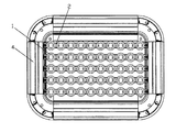
図1〜図4に示すように、本発明の対流放熱式LED照明ランプは、複数のLED発光放熱ユニット1と、LED発光放熱ユニット1を取り付ける基部2と、フレーム4とを備え、基部2とフレーム4とは接続固定されている。
As shown in FIGS. 1 to 4, the convection heat radiation type LED lighting lamp of the present invention includes a plurality of LED light emission heat radiation units 1, a
前記基部2は互いに一定の間隔で配列された複数の帯状体であり、透かし彫り状構造を形成している。これによって、この基部2には外気と直接対流可能な複数の通路が形成されている。前記帯状体には間隔を空けてLED発光放熱ユニット1が設けられている。このLED発光放熱ユニット1は、それぞれ独立して外気と接触可能であり、それによって別々に放熱している。
The
前記LED発光放熱ユニット1は、LEDチップ11と、回路基板3と、回路端子14(本実施形態においては正極及び負極のリード)と、対応する放熱器12とを備えるとともに、独立した防水密封体を構成している。前記回路基板3は独立して防水密封されている。
The LED light-emitting and radiating unit 1 includes an LED chip 11, a circuit board 3, a circuit terminal 14 (positive and negative leads in the present embodiment), and a
前記LED発光放熱ユニット1の回路端子14はその底部から引き出された電極リードであり、この電極リードは基部2におけるLED発光放熱ユニット1の取付面とは反対の端面に設けられた凹溝21を介して電源端子14まで引き回されている。前記電極リードは、前記凹溝21に配置された後、コロイド状物質によって固定密封されている。前記凹溝21は帯状の凹溝である。
The
また、前記LED発光放熱ユニット1の放熱器12における一方の端面には、LEDチップ11及び回路基板3を設置するための載置部121が開口形成されている。前記LEDチップ11の上方には1つのレンズ13が設けられており、LED発光放熱ユニット1とともに全体が防水密封されている。このレンズ13は密封材料によって回路基板3を密封する目的を果たすことができ、LEDの発光分布を効果的に調節することもできる。
Further, a
前記基部2は金属材料からなる。
The
図5に示すように、本発明に係る基部2は、1つの格子状構造を有していてもよい。この格子状構造には、間隔を空けてLED発光放熱ユニット1が設けられる。
As shown in FIG. 5, the
Claims (8)
前記基部(2)は、互いに一定の間隔で配列された複数の帯状体又は1つの格子状体で透かし彫り状構造を形成しており、これによって前記基部(2)には外気と直接対流可能な複数の通路が形成され、
前記LED発光放熱ユニット(1)は、
前記帯状体又は格子状構造に間隔を空けて設けられており、
LEDチップ(11)と、
回路基板(3)と、
回路端子(14)と、
対応する放熱器(12)とを備えるとともに、独立した防水密封体を構成している
ことを特徴とする対流放熱式LED照明ランプ。 A plurality of LED light emitting and radiating units (1), a base (2) for attaching the LED light emitting and radiating units (1), and a frame (4) are provided, and the base (2) and the frame (4) are connected and fixed. A convection heat radiation LED lighting lamp,
The base part (2) forms an openwork structure with a plurality of strips or one lattice-like body arranged at a constant interval from each other, so that the base (2) can directly convect with the outside air. Multiple passages are formed,
The LED light emitting and radiating unit (1)
Are provided at intervals in the strip or lattice structure,
An LED chip (11);
A circuit board (3);
A circuit terminal (14);
A convection heat radiation type LED lighting lamp comprising a corresponding heat radiator (12) and constituting an independent waterproof sealed body.
前記LED発光放熱ユニット(1)は、前記基部(2)においてアレイ状に並べられており、方形、円形、楕円形、台形、六角形又は梅の花形を形成している
ことを特徴とする対流放熱式LED照明ランプ。 In claim 1,
The LED light emitting and radiating units (1) are arranged in an array at the base (2), and form a square, a circle, an ellipse, a trapezoid, a hexagon, or a plum blossom. Heat radiation type LED lighting lamp.
前記LED発光放熱ユニットの回路端子(14)は、その底部から引き出された電極リードであり、
前記電極リードは、前記基部における発光放熱ユニット取付面とは反対の端面に設けられた凹溝(21)を介して電源端子まで引き回されている
ことを特徴とする対流放熱式LED照明ランプ。 In claim 1,
The circuit terminal (14) of the LED light-emitting and radiating unit is an electrode lead drawn from the bottom thereof,
The convection heat radiation type LED lighting lamp, wherein the electrode lead is routed to a power supply terminal through a concave groove (21) provided on an end surface of the base opposite to the light emitting and heat radiation unit mounting surface.
前記電極リードは、前記凹溝(21)に配置された後、コロイド状物質によって固定密封されている
ことを特徴とする対流放熱式LED照明ランプ。 In claim 3,
The electrode lead is disposed in the concave groove (21), and then fixed and sealed with a colloidal substance.
前記凹溝(21)は帯状の凹溝である
ことを特徴とする対流放熱式LED照明ランプ。 In claim 3 or 4,
The convection heat radiation type LED lighting lamp, wherein the groove (21) is a belt-like groove.
前記LED発光放熱ユニット(1)の放熱器(12)における一方の端面には、LEDチップ(11)及び回路基板(3)を設置するための載置部(121)が開口形成されている
ことを特徴とする対流放熱式LED照明ランプ。 In claim 1,
A mounting portion (121) for installing the LED chip (11) and the circuit board (3) is formed in one end face of the radiator (12) of the LED light emitting and radiating unit (1). Convection heat radiation type LED lighting lamp characterized by
前記LEDチップ(11)の上方には、1つのレンズ(13)が覆うように設けられており、前記LED発光放熱ユニット(1)とともに全体が防水密封されている
ことを特徴とする対流放熱式LED照明ランプ。 In claim 1,
A convection heat dissipation type characterized in that a single lens (13) is provided above the LED chip (11) so as to cover the whole and is waterproof and sealed together with the LED light-emitting / radiation unit (1). LED lighting lamp.
前記基部(2)は、金属材料からなる
ことを特徴とする対流放熱式LED照明ランプ。 In claim 1,
The said base (2) consists of metal materials, The convection heat dissipation type | mold LED lighting lamp characterized by the above-mentioned.
Applications Claiming Priority (3)
| Application Number | Priority Date | Filing Date | Title |
|---|---|---|---|
| CN200810204172.5 | 2008-12-08 | ||
| CN2008102041725A CN101482252B (en) | 2008-12-08 | 2008-12-08 | Convection cooling type LED illumination device |
| PCT/CN2009/070109 WO2010066117A1 (en) | 2008-12-08 | 2009-01-12 | Convective heat-dissipating led illumination lamp |
Publications (2)
| Publication Number | Publication Date |
|---|---|
| JP2012500457A true JP2012500457A (en) | 2012-01-05 |
| JP5628805B2 JP5628805B2 (en) | 2014-11-19 |
Family
ID=40879474
Family Applications (1)
| Application Number | Title | Priority Date | Filing Date |
|---|---|---|---|
| JP2011523291A Active JP5628805B2 (en) | 2008-12-08 | 2009-01-12 | Convection heat radiation type LED lighting lamp |
Country Status (7)
| Country | Link |
|---|---|
| US (1) | US20110051415A1 (en) |
| EP (1) | EP2365246B1 (en) |
| JP (1) | JP5628805B2 (en) |
| CN (1) | CN101482252B (en) |
| CY (1) | CY1118155T1 (en) |
| ES (1) | ES2583640T3 (en) |
| WO (1) | WO2010066117A1 (en) |
Cited By (1)
| Publication number | Priority date | Publication date | Assignee | Title |
|---|---|---|---|---|
| WO2014069717A1 (en) * | 2012-10-30 | 2014-05-08 | (주)디엠라이트 | Flat led lighting device |
Families Citing this family (12)
| Publication number | Priority date | Publication date | Assignee | Title |
|---|---|---|---|---|
| CN101706074B (en) * | 2009-11-28 | 2011-08-17 | 滁州恒恩光电科技有限公司 | Modularized assembled LED streetlamp |
| KR101641860B1 (en) * | 2010-05-12 | 2016-07-29 | 엘지이노텍 주식회사 | Light-emitting element array, Backlight apparatus, and Illumination apparatus |
| CN102155716A (en) * | 2011-04-03 | 2011-08-17 | 东莞勤上光电股份有限公司 | LED (light-emitting diode) radiator |
| CN103032704B (en) * | 2011-09-30 | 2016-02-03 | 深圳市邦贝尔电子有限公司 | Led |
| CN102392995B (en) * | 2011-11-18 | 2016-01-27 | 深圳市华星光电技术有限公司 | A kind of backboard, backlight module and liquid crystal indicator |
| US9166133B2 (en) * | 2012-03-15 | 2015-10-20 | Panasonic Intellectual Property Management Co., Ltd. | Substrate for LED, LED module, and LED bulb |
| US9115885B2 (en) * | 2012-04-12 | 2015-08-25 | Amerlux Inc. | Water tight LED assembly with connector through lens |
| CN103527947A (en) * | 2013-07-18 | 2014-01-22 | 邯郸市天之虹光电科技有限公司 | Modularized LED drive circuit |
| USD737501S1 (en) * | 2013-12-30 | 2015-08-25 | Hangzhou Hpwinner Opto Corporation | LED lens |
| USD956308S1 (en) * | 2018-02-01 | 2022-06-28 | Lead Opto-Technology Co., Ltd. | Solar LED wall light |
| US11666045B2 (en) * | 2021-01-04 | 2023-06-06 | Robert Joseph Marques | Submersible illuminating apparatus |
| USD992800S1 (en) * | 2023-02-01 | 2023-07-18 | Yu Chen | Solar flood light |
Citations (9)
| Publication number | Priority date | Publication date | Assignee | Title |
|---|---|---|---|---|
| JP3129417U (en) * | 2006-03-30 | 2007-02-22 | 鴻坤科技股▲ふん▼有限公司 | LED projection light source module |
| JP3142664U (en) * | 2008-04-10 | 2008-06-19 | 林健峯 | LED lighting |
| JP3143732U (en) * | 2008-01-28 | 2008-07-31 | 能▲是▼精密工業股▲分▼有限公司 | Light emitting diode lamp |
| US20080186712A1 (en) * | 2007-02-02 | 2008-08-07 | Lighthouse Technology Co., Ltd. | Light emitting diode |
| CN101251230A (en) * | 2007-12-20 | 2008-08-27 | 和谐光电科技(泉州)有限公司 | Modularized high-power LED road lamp as well as standardization LED light source module group unit thereof |
| JP2008258007A (en) * | 2007-04-05 | 2008-10-23 | Matsushita Electric Ind Co Ltd | Street light |
| JP3146628U (en) * | 2007-09-14 | 2008-11-20 | 安提亞科技股▲ふん▼有限公司 | Light emitting diode lamp |
| US20100085751A1 (en) * | 2008-03-26 | 2010-04-08 | Jeff Shaner | Enclosures for Light Sources |
| JP2010218852A (en) * | 2009-03-16 | 2010-09-30 | Chen Gaoshan | Module structure of heat dispersion unit for led light |
Family Cites Families (10)
| Publication number | Priority date | Publication date | Assignee | Title |
|---|---|---|---|---|
| CN2752889Y (en) * | 2004-11-08 | 2006-01-18 | 北京金立翔真彩科技有限公司 | Permeability LED display screen |
| CN200949803Y (en) * | 2006-08-15 | 2007-09-19 | 上海兴禄科技实业有限公司 | High power LED honeycomb heating radiator |
| US7712926B2 (en) * | 2006-08-17 | 2010-05-11 | Koninklijke Philips Electronics N.V. | Luminaire comprising adjustable light modules |
| JP3927592B1 (en) * | 2006-09-22 | 2007-06-13 | 株式会社コマデン | LED module and LED display device |
| CN101042226B (en) * | 2007-04-20 | 2010-05-19 | 诸建平 | High power LED lighting lamp model set |
| CN101315165B (en) * | 2007-05-28 | 2011-04-20 | 元瑞科技股份有限公司 | Illuminating apparatus |
| CN101089461A (en) * | 2007-06-11 | 2007-12-19 | 安提亚科技股份有限公司 | Twist type LED module and LED device |
| CN201145248Y (en) * | 2007-12-28 | 2008-11-05 | 上海三思电子工程有限公司 | LED lighting lamp with cooling structure |
| CN101566325B (en) * | 2008-04-23 | 2013-06-05 | 富准精密工业(深圳)有限公司 | Light-emitting diode lamp |
| US7857486B2 (en) * | 2008-06-05 | 2010-12-28 | Fu Zhun Precision Industry (Shen Zhen) Co., Ltd. | LED lamp assembly having heat pipes and finned heat sinks |
-
2008
- 2008-12-08 CN CN2008102041725A patent/CN101482252B/en active Active
-
2009
- 2009-01-12 WO PCT/CN2009/070109 patent/WO2010066117A1/en active Application Filing
- 2009-01-12 JP JP2011523291A patent/JP5628805B2/en active Active
- 2009-01-12 ES ES09831394.3T patent/ES2583640T3/en active Active
- 2009-01-12 US US12/934,995 patent/US20110051415A1/en not_active Abandoned
- 2009-01-12 EP EP09831394.3A patent/EP2365246B1/en not_active Not-in-force
-
2016
- 2016-07-20 CY CY20161100714T patent/CY1118155T1/en unknown
Patent Citations (9)
| Publication number | Priority date | Publication date | Assignee | Title |
|---|---|---|---|---|
| JP3129417U (en) * | 2006-03-30 | 2007-02-22 | 鴻坤科技股▲ふん▼有限公司 | LED projection light source module |
| US20080186712A1 (en) * | 2007-02-02 | 2008-08-07 | Lighthouse Technology Co., Ltd. | Light emitting diode |
| JP2008258007A (en) * | 2007-04-05 | 2008-10-23 | Matsushita Electric Ind Co Ltd | Street light |
| JP3146628U (en) * | 2007-09-14 | 2008-11-20 | 安提亞科技股▲ふん▼有限公司 | Light emitting diode lamp |
| CN101251230A (en) * | 2007-12-20 | 2008-08-27 | 和谐光电科技(泉州)有限公司 | Modularized high-power LED road lamp as well as standardization LED light source module group unit thereof |
| JP3143732U (en) * | 2008-01-28 | 2008-07-31 | 能▲是▼精密工業股▲分▼有限公司 | Light emitting diode lamp |
| US20100085751A1 (en) * | 2008-03-26 | 2010-04-08 | Jeff Shaner | Enclosures for Light Sources |
| JP3142664U (en) * | 2008-04-10 | 2008-06-19 | 林健峯 | LED lighting |
| JP2010218852A (en) * | 2009-03-16 | 2010-09-30 | Chen Gaoshan | Module structure of heat dispersion unit for led light |
Cited By (2)
| Publication number | Priority date | Publication date | Assignee | Title |
|---|---|---|---|---|
| WO2014069717A1 (en) * | 2012-10-30 | 2014-05-08 | (주)디엠라이트 | Flat led lighting device |
| US10228121B2 (en) | 2012-10-30 | 2019-03-12 | Dmlite Co., Ltd. | LED flat lighting device |
Also Published As
| Publication number | Publication date |
|---|---|
| JP5628805B2 (en) | 2014-11-19 |
| CN101482252A (en) | 2009-07-15 |
| WO2010066117A1 (en) | 2010-06-17 |
| ES2583640T3 (en) | 2016-09-21 |
| CN101482252B (en) | 2010-10-13 |
| CY1118155T1 (en) | 2017-06-28 |
| US20110051415A1 (en) | 2011-03-03 |
| EP2365246A1 (en) | 2011-09-14 |
| EP2365246B1 (en) | 2016-04-20 |
| EP2365246A4 (en) | 2013-09-11 |
Similar Documents
| Publication | Publication Date | Title |
|---|---|---|
| JP5628805B2 (en) | Convection heat radiation type LED lighting lamp | |
| JP5303319B2 (en) | Assembly type LED lighting equipment | |
| JP5746315B2 (en) | LED illumination module and illumination lamp using the same | |
| KR20110101789A (en) | Lighting cover having air pipe and led lighting apparatus using the same | |
| TWI414717B (en) | Light-emitting diode module with heat dissipating structure and lamp with light-emitting diode module | |
| JP3972056B1 (en) | Lighting device | |
| JP2009032590A (en) | Led lamp attained by multi-stage layer substrate, and diffusing heat instantly | |
| KR101034482B1 (en) | Lamp | |
| US9752770B2 (en) | Light-emitting diode light fixture with channel-type heat dissipation system | |
| JP3166617U (en) | High power LED lighting | |
| JP2011228255A (en) | Optical unit and lighting device | |
| KR101393509B1 (en) | Led lamp for tunnel | |
| JP4944221B2 (en) | LED lamp achieved by multi-layer substrate and dissipating heat instantly | |
| CN201377692Y (en) | Water-proof LED lamp | |
| WO2018133509A1 (en) | Led module and lighting fixture | |
| GB2464518A (en) | Outdoor light emitting diode lamp with sunshade | |
| KR101518749B1 (en) | LED module for ceiling mounting structure of an LED lighting | |
| JP2014143161A (en) | Light projector | |
| JP2012079610A (en) | Fluorescent lamp type led lamp | |
| KR101289700B1 (en) | Light Emitting Diode Module And Light Emitting Diode Streetlight Using The Same | |
| KR20110001430A (en) | The lighting fixture that using led | |
| CN211925493U (en) | LED ceiling spotlight | |
| FI123058B (en) | Led lighting fixture | |
| JP3203682U (en) | Full-angle light-emitting diode lamp | |
| TWI420040B (en) | Led lamp assembly |
Legal Events
| Date | Code | Title | Description |
|---|---|---|---|
| A977 | Report on retrieval |
Free format text: JAPANESE INTERMEDIATE CODE: A971007 Effective date: 20120913 |
|
| A131 | Notification of reasons for refusal |
Free format text: JAPANESE INTERMEDIATE CODE: A131 Effective date: 20121002 |
|
| A601 | Written request for extension of time |
Free format text: JAPANESE INTERMEDIATE CODE: A601 Effective date: 20121226 |
|
| A602 | Written permission of extension of time |
Free format text: JAPANESE INTERMEDIATE CODE: A602 Effective date: 20130108 |
|
| A521 | Request for written amendment filed |
Free format text: JAPANESE INTERMEDIATE CODE: A523 Effective date: 20130123 |
|
| RD02 | Notification of acceptance of power of attorney |
Free format text: JAPANESE INTERMEDIATE CODE: A7422 Effective date: 20130123 |
|
| A521 | Request for written amendment filed |
Free format text: JAPANESE INTERMEDIATE CODE: A821 Effective date: 20130123 |
|
| A131 | Notification of reasons for refusal |
Free format text: JAPANESE INTERMEDIATE CODE: A131 Effective date: 20130806 |
|
| A521 | Request for written amendment filed |
Free format text: JAPANESE INTERMEDIATE CODE: A523 Effective date: 20131031 |
|
| A131 | Notification of reasons for refusal |
Free format text: JAPANESE INTERMEDIATE CODE: A131 Effective date: 20140311 |
|
| A601 | Written request for extension of time |
Free format text: JAPANESE INTERMEDIATE CODE: A601 Effective date: 20140611 |
|
| A602 | Written permission of extension of time |
Free format text: JAPANESE INTERMEDIATE CODE: A602 Effective date: 20140618 |
|
| A521 | Request for written amendment filed |
Free format text: JAPANESE INTERMEDIATE CODE: A523 Effective date: 20140708 |
|
| TRDD | Decision of grant or rejection written | ||
| A01 | Written decision to grant a patent or to grant a registration (utility model) |
Free format text: JAPANESE INTERMEDIATE CODE: A01 Effective date: 20140902 |
|
| A61 | First payment of annual fees (during grant procedure) |
Free format text: JAPANESE INTERMEDIATE CODE: A61 Effective date: 20141002 |
|
| R150 | Certificate of patent or registration of utility model |
Ref document number: 5628805 Country of ref document: JP Free format text: JAPANESE INTERMEDIATE CODE: R150 |
|
| R250 | Receipt of annual fees |
Free format text: JAPANESE INTERMEDIATE CODE: R250 |
|
| R250 | Receipt of annual fees |
Free format text: JAPANESE INTERMEDIATE CODE: R250 |
|
| R250 | Receipt of annual fees |
Free format text: JAPANESE INTERMEDIATE CODE: R250 |
|
| R250 | Receipt of annual fees |
Free format text: JAPANESE INTERMEDIATE CODE: R250 |
|
| R250 | Receipt of annual fees |
Free format text: JAPANESE INTERMEDIATE CODE: R250 |
|
| R250 | Receipt of annual fees |
Free format text: JAPANESE INTERMEDIATE CODE: R250 |
|
| R250 | Receipt of annual fees |
Free format text: JAPANESE INTERMEDIATE CODE: R250 |