JP2012247052A - Fluid dynamic pressure bearing device - Google Patents
Fluid dynamic pressure bearing device Download PDFInfo
- Publication number
- JP2012247052A JP2012247052A JP2011121762A JP2011121762A JP2012247052A JP 2012247052 A JP2012247052 A JP 2012247052A JP 2011121762 A JP2011121762 A JP 2011121762A JP 2011121762 A JP2011121762 A JP 2011121762A JP 2012247052 A JP2012247052 A JP 2012247052A
- Authority
- JP
- Japan
- Prior art keywords
- shaft
- peripheral surface
- flange
- annular
- bearing device
- Prior art date
- Legal status (The legal status is an assumption and is not a legal conclusion. Google has not performed a legal analysis and makes no representation as to the accuracy of the status listed.)
- Withdrawn
Links
Images


Abstract
Description
本発明は、軸受部材の内周面と軸部の外周面との間のラジアル軸受隙間に生じる潤滑油の動圧作用により軸部を回転自在に支持する流体動圧軸受装置に関する。 The present invention relates to a fluid dynamic bearing device that rotatably supports a shaft portion by a dynamic pressure action of lubricating oil generated in a radial bearing gap between an inner peripheral surface of a bearing member and an outer peripheral surface of the shaft portion.
流体動圧軸受装置は、優れた回転精度および静粛性を有するため、例えば、各種ディスク駆動装置(HDDの磁気ディスク駆動装置や、CD−ROM等の光ディスク駆動装置等)のスピンドルモータ用、レーザビームプリンタ(LBP)のポリゴンスキャナモータ用、あるいはプロジェクタのカラーホイールモータ用として好適に使用されている。 Since the fluid dynamic bearing device has excellent rotational accuracy and quietness, for example, for spindle motors of various disk drive devices (such as HDD magnetic disk drive devices and CD-ROM optical disk drive devices), laser beams, etc. It is suitably used for a polygon scanner motor of a printer (LBP) or a color wheel motor of a projector.
例えば特許文献1に示されている流体動圧軸受装置は、軸部と、軸部の上端に設けられたハブと、内周に軸部が挿入された軸受部材(スリーブ)とを備える。ハブは、軸部の外周面の上端に固定された円盤部と、円盤部の外周部から下方に延びた円筒部と、円筒部の下端から外径に張り出した鍔部と、円盤部の径方向略中央部から下方に突出した環状突出部とを備える。軸部が回転すると、軸部の外周面と軸受部材の内周面との間にラジアル軸受隙間が形成されると共に、軸受部材の上端面とハブの円盤部の下側端面との間にスラスト軸受隙間が形成され、これらのラジアル軸受隙間及びスラスト軸受隙間の油膜に生じる動圧作用で、軸部及びハブが回転自在に支持される。また、ハブの環状突出部の内周面と軸受部材の外周面との間には断面楔形のシール空間が形成され、このシール空間の内部に油面を保持することで、軸受部材の内部に満たされた油の外部への漏れ出しを防止している。
For example, a fluid dynamic bearing device disclosed in
近年、HDD等の小型化、薄型化、及び軽量化が進み、HDD等に組み込まれる流体動圧軸受装置にも上記の特性が強く要求されている。例えば、ハブを薄肉化すれば、材料減による軽量化が図られると共に、減じた肉厚の分だけ流体動圧軸受装置の小型化及び薄型化が図られる。しかし、上記の流体動圧軸受装置では、軸部とハブとが別体に形成され、軸部の外周面にハブの円盤部の内周面が嵌合固定されているため、ハブを薄肉化すると軸部とハブとの嵌合面積が減少し、両者の締結強度及び組付精度(直角度等)が低下する恐れがある。 In recent years, HDDs and the like have become smaller, thinner, and lighter, and the above characteristics are strongly demanded for fluid dynamic bearing devices incorporated in HDDs and the like. For example, if the hub is made thinner, the weight can be reduced by reducing the material, and the fluid dynamic bearing device can be made smaller and thinner by the reduced thickness. However, in the above fluid dynamic bearing device, the shaft portion and the hub are formed separately, and the inner peripheral surface of the disc portion of the hub is fitted and fixed to the outer peripheral surface of the shaft portion. Then, the fitting area between the shaft portion and the hub decreases, and the fastening strength and assembly accuracy (perpendicularity, etc.) of both may decrease.
例えば、特許文献2に示されている流体動圧軸受装置のように、軸部とハブとを鍛造により一体成形すれば、これらを別体に形成する場合と比べて両者の締結強度(境界部における強度)や直角度等を高めることができる。これにより、ハブの薄肉化が可能となり、流体動圧軸受装置の小型化、薄型化、及び軽量化が図られる。
For example, as in the fluid dynamic pressure bearing device disclosed in
しかし、上記の流体動圧軸受装置のハブは、円盤部の径方向略中央部に下方に突出した環状突出部が設けられるため、円盤部及び環状突出部を鍛造で一体成形することは極めて困難である。 However, since the hub of the fluid dynamic pressure bearing device described above is provided with an annular projecting portion projecting downward at a substantially central portion in the radial direction of the disc portion, it is extremely difficult to integrally form the disc portion and the annular projecting portion by forging. It is.
また、上記の流体動圧軸受装置では、軸部とその外周を囲む環状突出部とが一体形成されるため、軸部の外周面に研削加工を施す際に様々な不具合が生じる。具体的には、軸部の外周面の一部が環状突出部で囲まれた状態となるため、軸部の外周面への砥石のアクセスが困難となり、生産性が低下する。また、砥石の大きさが、軸部と環状突出部の間の隙間に挿入可能な大きさに制限されるため、非常に小さな砥石しか使用することができず、摩耗により頻繁に交換する必要が生じて生産性がさらに低下する。 Further, in the above fluid dynamic pressure bearing device, the shaft portion and the annular projecting portion surrounding the outer periphery thereof are integrally formed, and thus various problems occur when grinding the outer peripheral surface of the shaft portion. Specifically, since a part of the outer peripheral surface of the shaft portion is surrounded by the annular projecting portion, it becomes difficult to access the grindstone to the outer peripheral surface of the shaft portion, and productivity is reduced. In addition, since the size of the grindstone is limited to a size that can be inserted into the gap between the shaft portion and the annular protrusion, only a very small grindstone can be used, and it is necessary to replace it frequently due to wear. This will further reduce productivity.
本発明は、上記の事情に鑑みてなされたものであり、ハブの円盤部の径方向略中央部に環状突出部を有する流体動圧軸受装置において、ハブと軸部との締結強度及び組付精度を確保すること、及び、製造を容易化して生産性を高めることを解決すべき技術的課題とするものである。 The present invention has been made in view of the above circumstances, and in a fluid dynamic bearing device having an annular projecting portion at a substantially central portion in the radial direction of the disk portion of the hub, the fastening strength and assembly between the hub and the shaft portion are provided. Ensuring accuracy and facilitating manufacturing to increase productivity are technical issues to be solved.
前記課題を解決するためになされた本発明は、研削加工が施された軸受面を外周に有する軸部と、前記軸部の一端から外径側に延びる円盤部、及び、前記円盤部の半径方向中間部から軸方向他端側に突出した環状突出部を有するハブと、内周に前記軸部が挿入された軸受部材と、前記軸部の軸受面と前記軸受部材の内周面との間のラジアル軸受隙間に生じる流体の動圧作用で前記軸部を回転自在に支持するラジアル軸受部と、前記環状突出部の内周面と前記軸受部材の外周面との間に形成され、前記軸受部材の内部に満たされた流体と外気との界面を保持するシール空間とを備えた流体動圧軸受装置において、前記円盤部のうち、少なくとも前記環状突出部よりも内径側の第1領域を前記軸部と一体形成してフランジ一体軸を構成し、該フランジ一体軸にこれと別体に形成した前記環状突出部を固定したことを特徴とするものである。 The present invention made in order to solve the above problems includes a shaft portion having a bearing surface subjected to grinding on the outer periphery, a disk portion extending from one end of the shaft portion to the outer diameter side, and a radius of the disk portion. A hub having an annular projecting portion projecting from the intermediate portion in the axial direction to the other end side in the axial direction, a bearing member in which the shaft portion is inserted into an inner periphery, a bearing surface of the shaft portion, and an inner peripheral surface of the bearing member Formed between a radial bearing portion that rotatably supports the shaft portion by a dynamic pressure action of a fluid generated in a radial bearing gap between the inner peripheral surface of the annular projecting portion and an outer peripheral surface of the bearing member, In the fluid dynamic pressure bearing device including a seal space that holds an interface between the fluid filled in the bearing member and the outside air, at least the first region on the inner diameter side of the annular projecting portion of the disk portion. A flange integrated shaft is formed integrally with the shaft portion, and the flange is formed. It is characterized in that it has fixed the annular protruding portion formed separately from the this-di integral shaft.
このように、本発明に係る流体動圧軸受装置では、ハブの円盤部のうち、少なくとも環状突出部よりも内径側の第1領域を軸部と一体形成してフランジ一体軸を構成し、該フランジ一体軸にこれと別体に形成した環状突出部を固定した。具体的には、例えば、円盤部のうち、環状突出部よりも外径側の第2領域を環状突出部と一体形成して環状部材を構成し、フランジ一体軸のフランジ部(円盤部の第1領域)の外周面に環状部材を嵌合固定した構成とすることができる。このように、円盤部を環状突出部を境界として分割し、環状突出部を第2領域の内径端に設けることにより、円盤部の半径方向中間部から一体に突出させる場合と比べて、ハブの形成を容易化することができる。これにより、例えばフランジ一体軸及び環状部材を、それぞれ塑性加工で形成した素形材に研削加工を施すことにより製作することが可能となる。 As described above, in the fluid dynamic pressure bearing device according to the present invention, at least the first region on the inner diameter side of the annular projecting portion of the disc portion of the hub is integrally formed with the shaft portion to constitute the flange integrated shaft, An annular protrusion formed separately from the flange integrated shaft was fixed. Specifically, for example, in the disk portion, a second region on the outer diameter side of the annular projecting portion is integrally formed with the annular projecting portion to constitute the annular member, and the flange portion of the flange integrated shaft (the first portion of the disc portion). It is possible to adopt a configuration in which an annular member is fitted and fixed to the outer peripheral surface of one region. In this way, by dividing the disk portion with the annular protrusion as a boundary and providing the annular protrusion at the inner diameter end of the second region, compared to the case where the hub portion is integrally protruded from the radial intermediate portion of the disk portion, Formation can be facilitated. Accordingly, for example, the flange-integrated shaft and the annular member can be manufactured by grinding each of the shaped members formed by plastic working.
また、上記のようにフランジ一体軸と環状突出部とを別体に形成することで、フランジ一体軸に環状突出部を組み付ける前に軸部の外周の軸受面に研削加工を施すことができるため、環状突出部により軸受面の研削加工が妨げられず、生産性が向上する。 In addition, since the flange-integrated shaft and the annular protrusion are formed separately as described above, the outer peripheral bearing surface of the shaft portion can be ground before the annular protrusion is assembled to the flange-integrated shaft. The grinding of the bearing surface is not hindered by the annular protrusion, and the productivity is improved.
また、フランジ一体軸のフランジ部の外周面と環状部材の内周面とを嵌合固定することで、例えば軸部の外周にハブを嵌合固定する場合と比べ、嵌合部の径が大きくなって両者の嵌合面積が増大するため、両者の締結強度及び組付精度を高めることができる。 Also, by fitting and fixing the outer peripheral surface of the flange portion of the flange-integrated shaft and the inner peripheral surface of the annular member, for example, the diameter of the fitting portion is larger than when the hub is fitted and fixed to the outer periphery of the shaft portion. Thus, since the fitting area between the two increases, both the fastening strength and the assembling accuracy can be increased.
環状部材とフランジ一体軸との組付精度を考慮すると、環状部材の内周面とフランジ一体軸のフランジ部の外周面とを圧入することが好ましい。 In consideration of the assembly accuracy between the annular member and the flange-integrated shaft, it is preferable to press-fit the inner peripheral surface of the annular member and the outer peripheral surface of the flange portion of the flange-integrated shaft.
環状部材の内周面とフランジ一体軸のフランジ部の外周面との嵌合部をレーザ溶接や接着剤により封止すれば、両者の締結強度がさらに高められると共に、嵌合部からの潤滑流体の漏れ出しを確実に防止できる。 If the fitting portion between the inner peripheral surface of the annular member and the outer peripheral surface of the flange portion of the flange-integrated shaft is sealed with laser welding or an adhesive, the fastening strength between the two can be further increased, and the lubricating fluid from the fitting portion Can be reliably prevented.
環状部材の内周面及びフランジ一体軸のフランジ部の外周面の双方に段部を設け、両者をインロー嵌合させれば、円筒面同士で嵌合させる場合と比べて嵌合面積を大きくして締結強度をさらに高めることができる。また、環状部材の内周面及びフランジ一体軸のフランジ部の外周面に設けた段部(平坦面)同士を軸方向に当接させることで、環状部材と円盤部の第1領域とを軸方向で位置決めすることができるため、組付精度をさらに高めることができる。 If stepped portions are provided on both the inner peripheral surface of the annular member and the outer peripheral surface of the flange portion of the flange-integrated shaft, and the both are fitted with a spigot, the fitting area is increased compared to the case where the cylindrical surfaces are fitted with each other. The fastening strength can be further increased. Further, the annular member and the first region of the disk portion are pivoted by bringing the stepped portions (flat surfaces) provided on the inner peripheral surface of the annular member and the outer peripheral surface of the flange portion of the flange-integrated shaft into axial contact with each other. Since positioning can be performed in the direction, the assembling accuracy can be further increased.
ハブの構成は上記に限らず、例えば、円盤部全体と軸部とを一体形成することによりフランジ一体軸を構成し、このフランジ一体軸のフランジ部を構成する円盤部の端面に環状突出部を固定した構成とすることもできる。このように、円盤部と環状突出部とを別体に形成することで、ハブの形状が単純化されて形成を容易化することができ、例えば塑性加工で形成した素形材に研削加工を施すことによりハブ一体軸を製作することが可能となる。また、このように軸部及びハブの円盤部を一体形成することで、これらを別体に形成する場合と比べて、軸部と円盤部との締結強度(境界部における強度)及び直角度等を高めることができる。 The configuration of the hub is not limited to the above. For example, a flange-integrated shaft is formed by integrally forming the entire disk portion and the shaft portion, and an annular protruding portion is formed on the end surface of the disk portion constituting the flange portion of the flange-integrated shaft. A fixed configuration may also be used. In this way, by forming the disc portion and the annular protrusion separately, the shape of the hub can be simplified and the formation can be facilitated. This makes it possible to produce a hub integrated shaft. Further, by integrally forming the shaft portion and the disk portion of the hub in this way, the fastening strength (strength at the boundary portion) and the squareness of the shaft portion and the disk portion are compared with the case where they are formed separately. Can be increased.
上記の場合、フランジ一体軸に対する環状突出部の固定強度及び固定精度が問題となる。例えば、環状突出部、及び、環状突出部の一端から内径に延びる延在部を有するシール部材を設け、延在部の内周面を軸部の外周面に嵌合すれば、軸部の外周面に対する環状突出部の位置精度(同軸度等)を高めることができる。また、シール部材の延在部の端面をフランジ一体軸のフランジ部の端面に固定すれば、固定面積を十分に確保することができ、固定強度が高められる。 In the above case, the fixing strength and fixing accuracy of the annular protrusion with respect to the flange-integrated shaft become a problem. For example, if a seal member having an annular protruding portion and an extending portion extending from one end of the annular protruding portion to the inner diameter is provided and the inner peripheral surface of the extending portion is fitted to the outer peripheral surface of the shaft portion, the outer periphery of the shaft portion The positional accuracy (coaxiality etc.) of the annular protrusion with respect to the surface can be increased. Further, if the end surface of the extending portion of the seal member is fixed to the end surface of the flange portion of the flange-integrated shaft, a sufficient fixing area can be secured and the fixing strength can be increased.
シール部材の延在部の端面とフランジ一体軸のフランジ部の端面との間に、接着剤で満たされた環状の接着剤溜りを形成すれば、シール部材とフランジ部との固定強度をさらに高めることができると共に、シール部材の延在部とフランジ一体軸のフランジ部との間の隙間を接着剤で封止することができるため、この隙間を伝って潤滑流体が外部へ漏れ出す事態を確実に防止できる。 If an annular adhesive reservoir filled with an adhesive is formed between the end surface of the extending portion of the seal member and the end surface of the flange portion of the flange integral shaft, the fixing strength between the seal member and the flange portion is further increased. In addition, the gap between the extending portion of the seal member and the flange portion of the flange-integrated shaft can be sealed with an adhesive, so that it is ensured that the lubricating fluid leaks outside through this gap. Can be prevented.
シール部材と軸部との固定精度を高めるためには、シール部材の延在部の内周面を軸部の外周面に圧入(軽圧入)することが望ましい。しかし、軸部の一端にはフランジ部(ハブの円盤部)が一体形成されているため、シール部材を軸部の他端側から軸受面と摺動させながら圧入せざるを得ず、軸受面を傷つける恐れがある。そこで、軸部の外周面の一端に、軸受面よりも大径なガイド部を設け、このガイド部にシール部材の延在部の内周面を圧入すれば、シール部材の延在部の内周面と軸部の軸受面との間に隙間を設けることができるため、軸受面の損傷を防止できる。このガイド部に研削加工を施しておけば、軸部に対するシール部材の固定精度がさらに高められる。 In order to increase the fixing accuracy between the seal member and the shaft portion, it is desirable to press-fit (light press-fit) the inner peripheral surface of the extending portion of the seal member to the outer peripheral surface of the shaft portion. However, since the flange portion (the disk portion of the hub) is integrally formed at one end of the shaft portion, the seal member has to be press-fitted while sliding with the bearing surface from the other end side of the shaft portion. There is a risk of hurting. Therefore, if a guide portion having a larger diameter than the bearing surface is provided at one end of the outer peripheral surface of the shaft portion, and the inner peripheral surface of the extending portion of the seal member is press-fitted into this guide portion, the inner portion of the extending portion of the seal member is Since a gap can be provided between the peripheral surface and the bearing surface of the shaft portion, damage to the bearing surface can be prevented. If this guide portion is ground, the accuracy of fixing the seal member to the shaft portion can be further increased.
フランジ一体軸のフランジ部の端面のうち、少なくともシール部材の延在部の端面と対向する領域に研削加工を施しておけば、両者の密着性を高めることができるため、フランジ一体軸に対するシール部材の固定精度が高められる。 Of the end faces of the flange portion of the flange-integrated shaft, if at least the region facing the end surface of the extending portion of the seal member is ground, the adhesion between the two can be improved. The accuracy of fixing is improved.
以上のように、本発明の流体動圧軸受装置によれば、ハブの円盤部のうち、少なくとも環状突出部よりも内径側の第1領域を軸部と一体形成してフランジ一体軸を構成し、該フランジ一体軸にこれと別体に形成した環状突出部を固定することで、円盤部の径方向略中央部に環状突出部を有するハブを一体形成する場合と比べて、ハブと軸部との締結強度及び組付精度を確保することができ、且つ、製造を容易化して生産性を高めることができる。 As described above, according to the fluid dynamic pressure bearing device of the present invention, the flange integrated shaft is configured by integrally forming at least the first region on the inner diameter side of the annular projecting portion of the disc portion of the hub with the shaft portion. By fixing an annular protrusion formed separately from the flange-integrated shaft, the hub and the shaft are compared with a case where a hub having an annular protrusion is formed integrally at a substantially central portion in the radial direction of the disk portion. The fastening strength and the assembling accuracy can be ensured, and the manufacturing can be facilitated to increase the productivity.
以下、本発明の実施形態を図面に基づいて説明する。 Hereinafter, embodiments of the present invention will be described with reference to the drawings.
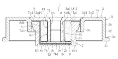
図1に、例えば2.5インチHDDのディスク駆動装置に用いられるスピンドルモータを示す。このスピンドルモータは、本発明の一実施形態に係る流体動圧軸受装置1と、流体動圧軸受装置1が取り付けられたブラケット6と、半径方向のギャップを介して対向させたステータコイル4およびロータマグネット5とを備えている。ステータコイル4はブラケット6に取り付けられ、ロータマグネット5は流体動圧軸受装置1のハブ3に取り付けられる。ハブ3には、回転体としてのディスク(図示省略)が所定の枚数搭載される。ステータコイル4に通電すると、ステータコイル4とロータマグネット5との間の電磁力でロータマグネット5が回転し、これによりハブ3、軸部2、及びディスクが一体となって回転する。
FIG. 1 shows a spindle motor used in, for example, a 2.5-inch HDD disk drive device. The spindle motor includes a fluid dynamic
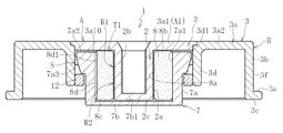
流体動圧軸受装置1は、図2に示すように、軸部2と、軸部2の一端に設けられたハブ3と、軸部2を回転自在に支持する軸受部材とで構成される。本実施形態では、軸受部材が、内周に軸部2を挿入した軸受スリーブ8と、内周に軸受スリーブ8を保持する有底筒状のハウジング7とで構成される。軸部2の下端には、抜け止め部材9が設けられる。尚、以下では、説明の便宜上、軸方向でハウジング7の開口側を上側、閉塞側を下側とする。
As shown in FIG. 2, the fluid dynamic
軸部2は、外径が2〜4mm程度に設定される。軸部2は、凹凸の無いストレートな円筒面状の外周面2aと、軸心に設けられた軸方向穴2bとを有する。軸方向穴2bは、軸部2を軸方向に貫通して設けられ、その内周面にネジ溝が形成される。軸部2の外周面2aはラジアル軸受面として機能する。
The
ハブ3は、軸部2の上端から外径に延びた円盤部3aと、円盤部3aの外周部から軸方向下方に延びた円筒部3bと、円筒部3bの下端部からさらに外径に延びた鍔部3cと、円盤部3aの半径方向中間部(図示例では半径方向略中央部)から下方に延びた円筒状の環状突出部3dとで構成される。鍔部3cの上側端面にはディスク搭載面3eが形成され、円筒部3bの外周面にはディスク嵌合面3fが形成される。ディスクの内孔をディスク嵌合面3fに嵌合させると共に、ディスクをディスク搭載面3eの上に載置し、この状態で図示しないクランパによってディスクの上面を押さえてディスク搭載面3e上に押し付けることにより、ディスクがハブ3に保持される。尚、軸部2の軸方向穴2bの上部は、クランパを固定するためのネジ穴として機能する。
The
本実施形態では、ハブ3の円盤部3aが、環状突出部3dよりも内径側の第1領域3a1と、環状突出部3dよりも外径側の第2領域3a2とに分割して形成される。そして、円盤部3aの第1領域3a1と軸部2とが一体形成されてフランジ一体軸Aを構成すると共に、円盤部3aの第2領域3a2、円筒部3b、鍔部3c、及び環状突出部3dが一体形成されて環状部材Bを構成する。
In the present embodiment, the
このように、円盤部3aの半径方向中間部から環状突出部3dが突出したハブ3を、環状突出部3dを境界として分割して形成することにより、円盤部3aの半径方向中間部から環状突出部3dを一体に突出させる場合と比べて、各部材(フランジ一体軸A及び環状部材B)の形状を簡略化して形成を容易化することができる。これにより、フランジ一体軸A及び環状部材Bを、金属の塑性加工(例えば金属板のプレス加工)で形成した素形材に研削加工を施すことで製造することができる。尚、フランジ一体軸A及び環状部材Bの素形材は、塑性加工に限らず、例えば旋削等の機械加工で形成することもできる。
In this manner, the
フランジ一体軸A及び環状部材Bの金属材料としては、例えば鋼材(ステンレス鋼、一般構造用鋼など)、アルミ合金、あるいはチタン合金等を使用することができる。また、フランジ一体軸A及び環状部材Bを異なる材料で形成することもできる。例えば、フランジ一体軸Aは耐摩耗性に優れた金属(例えばマルテンサイト系ステンレス鋼)で形成し、環状部材Bはロータマグネット5を取り付けるために磁性を有する金属(例えばフェライト系ステンレス鋼)で形成することができる。また、回転トルクの低減を図るために、環状部材Bをフランジ一体軸Aよりも軽い(低密度の)材料で形成してもよい。 As the metal material of the flange integral shaft A and the annular member B, for example, steel (stainless steel, general structural steel, etc.), aluminum alloy, titanium alloy, or the like can be used. Further, the flange-integrated shaft A and the annular member B can be formed of different materials. For example, the flange-integrated shaft A is formed of a metal having excellent wear resistance (for example, martensitic stainless steel), and the annular member B is formed of a magnetic metal (for example, ferritic stainless steel) for mounting the rotor magnet 5. can do. In order to reduce the rotational torque, the annular member B may be formed of a material that is lighter (low density) than the flange-integrated shaft A.
フランジ一体軸Aのうち、ラジアル軸受面として機能する軸部2の外周面2a、スラスト軸受面として機能するフランジ部A1(円盤部3aの第1領域3a1)の下側端面3a10、及び、スラスト軸受面を有する抜け止め部材9のフランジ部9aと当接する軸部2の下端面2cには研削加工(好ましくは1つの砥石による同時研削)が施される。これに加えて、環状部材Bのうち、ディスク搭載面3e及びディスク嵌合面3fに研削加工を施してもよい。
Out of the flange-integrated shaft A, the outer
軸部2の外周面2aには、表面硬化処理又はコーティング処理、あるいはこれらの双方を施してもよい。表面硬化処理としては、例えば真空焼入れ、真空浸炭処理、真空窒化処理、ガス軟窒化処理、あるいはイオン窒化処理等による表面硬化処理が挙げられる。コーティング処理としては、例えば無電解Niめっき、DLC、TiN、TiAlN、あるいはTiCによるコーティング処理が挙げられる。尚、表面処理やコーティング処理は、軸部2の外周面2aだけでなく、他の領域、例えばスラスト軸受隙間に面するハブ3の円盤部3aの下側端面3a10に施しても良い。あるいは、軸部2の外周面2aの耐摩耗性が十分であれば、表面効果処理やコーティング処理を省略してもよい。
The outer
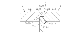
環状部材Bは、フランジ一体軸Aのフランジ部A1(円盤部3aの第1領域3a1)の外周面に嵌合固定(例えば圧入固定)される。本実施形態では、図3に示すように、環状部材Bの内周面及びフランジ一体軸Aのフランジ部の外周面にそれぞれ段部を設け、両者をインロー嵌合させている。詳しくは、フランジ一体軸Aのフランジ部の外周面に、大径外周面3a11、小径外周面3a12、及びこれらの間に設けられ、軸方向と直交する平坦面3a13を形成すると共に、環状部材Bの内周面の上端に、大径内周面3a21、小径内周面3a22、及びこれらの間に設けられ、軸方向と直交する平坦面3a23を形成する。そして、フランジ一体軸Aの大径外周面3a11及び小径外周面3a12がそれぞれ環状部材Bの大径内周面3a21及び小径内周面3a22に圧入され、これによりフランジ一体軸Aと環状部材Bの同軸度、特に、軸部2の外周面2a(軸受面)と環状突出部3dの内周面3d1(シール面)との同軸度が精度良く設定される。また、フランジ一体軸Aの平坦面3a13と環状部材Bの平坦面3a23とが当接し、これによりフランジ一体軸Aに対する環状部材Bの軸方向の位置精度、特に、円盤部3aの第1領域3a1の下側端面3a10(スラスト軸受面)に対するディスク搭載面3eの軸方向の位置精度が精度良く設定される。
The annular member B is fitted and fixed (for example, press-fitted and fixed) to the outer peripheral surface of the flange portion A1 (the first region 3a1 of the
フランジ一体軸Aと環状部材Bとの嵌合部は、レーザ溶接あるいは接着剤により封止される。図示例では、嵌合部の上端を全周にわたって封止する環状の封止部Gが設けられる。これにより、嵌合部の固定強度が高められると共に、嵌合部からの油漏れを確実に防止できる。 The fitting portion between the flange integrated shaft A and the annular member B is sealed by laser welding or an adhesive. In the example of illustration, the cyclic | annular sealing part G which seals the upper end of a fitting part over a perimeter is provided. Thereby, while fixing strength of a fitting part is raised, the oil leak from a fitting part can be prevented reliably.
抜け止め部材9は金属あるいは樹脂で形成され、円盤形状のフランジ部9aと、フランジ部9aの軸心から上方に延びた固定部9bとを有する。固定部9bの外周にはネジ溝が形成され、軸部2の軸方向穴2bの内周面に形成されたネジ穴の下端にネジ固定される。フランジ部9aは軸部2の外周面2aよりも外径に突出し、その上側端面9a1が軸部2の下端面2cと当接している。フランジ部9aは、軸受スリーブ8の下側端面8cとハウジング7の底部7bの上側端面7b1との軸方向間に配され、軸受スリーブ8と軸方向で係合することにより、軸部2の軸受スリーブ8からの抜け止めを行う。
The retaining
フランジ部9aの上側端面9a1は、スラスト軸受面として機能する。軸部2の下端面2cは研削により高精度な平坦面に仕上げられているため、フランジ部9aの上側端面9a1は軸部2の下端面2cの全面と良好に密着し、これにより、軸部2に対してフランジ部9aを高精度に位置決めすることができる。また、フランジ部9aの上側端面9a1と軸部2の下端面2cとを全周で密着させることにより、軸部2の軸方向穴2bへの潤滑油の侵入を抑えることができるため、ハウジング7の内部に満たされた潤滑油が軸方向穴2bを介して外部に漏れだす恐れを低減できる。
The upper end surface 9a1 of the
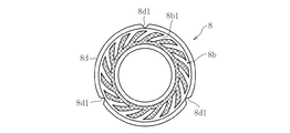
軸受スリーブ8は、金属や樹脂で円筒状に形成され、本実施形態では、例えば銅あるいは銅及び鉄を主成分とする焼結金属で形成される。軸受スリーブ8の内周面8aには、図4に示すように、ラジアル動圧発生部として、例えば軸方向に離隔した2つの領域にヘリングボーン形状の動圧溝8a1,8a2がそれぞれ形成される(クロスハッチングは丘部)。図示例では、上側の動圧溝8a1は軸方向非対称に形成されており、具体的には、軸方向中央部mより上側の領域の軸方向寸法X1が、下側の領域の軸方向寸法X2よりも大きくなっている(X1>X2)。下側の動圧溝8a2は軸方向対称に形成されている。軸受スリーブ8の外周面8dには、軸方向溝8d1が軸方向全長にわたって形成され、例えば3本の軸方向溝8d1が円周方向に等配される。
The
軸受スリーブ8の上側端面8b及び下側端面8cには、図5及び図6に示すように、それぞれスラスト動圧発生部として、例えばポンプインタイプのスパイラル形状の動圧溝8b1,8c1が形成される(クロスハッチングは丘部)。軸受スリーブ8の外周面8dには、軸方向溝8d1が形成される。軸方向溝8d1の本数は任意であり、例えば3本の軸方向溝8d1が円周方向等間隔に配される。
As shown in FIGS. 5 and 6, for example, pump-in type spiral-shaped dynamic pressure grooves 8b1 and 8c1 are formed on the
ハウジング7は、金属や樹脂で形成され、本実施形態では例えば樹脂の射出成形で形成される。ハウジング7は、図2に示すように、側部7a及び底部7bを一体に有する有底円筒状に形成される。側部7aの内周面7a1は、ストレートな円筒面状に形成され、軸受スリーブ8の外周面8dが隙間接着、圧入、接着剤介在下の圧入等により固定される。側部7aの外周面の上端には、図2に示すように、上方に向かって漸次拡径するテーパ状のシール面7a3が形成される。このシール面7a3は、ハブ3の環状突出部3dの円筒面状内周面3d1との間に、上方に向けて半径方向寸法が漸次縮小した環状のシール空間Sを形成する。シール空間Sは、軸部2の回転時、ハブ3の円盤部3aの下側端面3a10とハウジング7の上端面7a2との間の隙間を介して、第1のスラスト軸受部T1のスラスト軸受隙間の外径側、及び、軸方向溝8d1の上端と連通している。このシール空間Sの毛細管力により、ハウジング7の内部に充満された潤滑油の漏れ出しを防止する。
The
上記構成を組み立てた後、軸受スリーブ8の内部気孔を含めたハウジング7の内部の空間に潤滑油を充満させることにより、図2に示す流体動圧軸受装置1が完成する。このとき、油面はシール空間Sの内部に保持される。
After assembling the above-described configuration, the fluid
軸部2が回転すると、軸受スリーブ8の内周面8aと軸部2の外周面2aとの間にラジアル軸受隙間が形成されると共に、ラジアル動圧発生部(動圧溝8a1,8a2)により上記ラジアル軸受隙間に満たされた潤滑油の圧力が高められ、この圧力(動圧作用)により軸部2及びハブ3をラジアル方向に回転自在に非接触支持するラジアル軸受部R1,R2が構成される。
When the
これと同時に、ハブ3の円盤部3aの第1領域3a1の下側端面3a10と軸受スリーブ8の上側端面8bとの間、及び、抜け止め部材9のフランジ部9aの上側端面9a1と軸受スリーブ8の下側端面8cとの間にそれぞれスラスト軸受隙間が形成されると共に、スラスト動圧発生部(動圧溝8b1,8c1)により各スラスト軸受隙間に満たされた潤滑油の圧力が高められ、この圧力(動圧作用)により軸部2及びハブ3をスラスト方向一方(持ち上げる方向)に回転自在に非接触支持する第1のスラスト軸受部T1と、軸部2及びハブ3をスラスト方向他方(押し下げる方向)に回転自在に非接触支持する第2のスラスト軸受部T2とが構成される。
At the same time, between the lower end surface 3a10 of the first region 3a1 of the
このとき、軸受スリーブ8の外周面8dに形成された軸方向溝8d1により、潤滑油が流通可能な連通路が形成される。この連通路により、ハウジング7の内部に満たされた潤滑油に局部的な負圧が発生する事態を防止できる。特に本実施形態では、図4に示すように、軸受スリーブ8の内周面8aに形成された上側の動圧溝8a1が軸方向非対称な形状に形成されているため、軸部2の回転に伴ってラジアル軸受隙間の潤滑油が下方に押し込まれ、上記の連通路を介して潤滑油が循環し、これにより局部的な負圧の発生を確実に防止できる。
At this time, the axial groove 8d1 formed in the outer
本発明は、上記の実施形態に限られない。以下、本発明の他の実施形態を説明するが、上記の実施形態と同様の機能を有する箇所には同一の符号を付して重複説明を省略する。 The present invention is not limited to the above embodiment. Hereinafter, although other embodiment of this invention is described, the same code | symbol is attached | subjected to the location which has the same function as said embodiment, and duplication description is abbreviate | omitted.
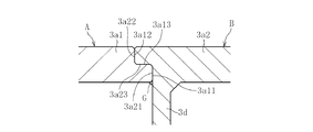
例えば、フランジ一体軸Aと環状部材Bとの嵌合状態は上記の実施形態に限られない。図7に示す実施形態では、大径外周面3a11と大径内周面3a21との嵌合部が、小径外周面3a12と小径内周面3a22との嵌合部よりも下方に位置し、環状部材Bの平坦面3a23がフランジ一体軸Aの平坦面3a13により下方から支持された状態となる。これにより、環状部材Bのディスク搭載面3eに搭載されるディスクの重量を、フランジ一体軸Aの平坦面3a13で支持することができる。
For example, the fitting state between the flange integrated shaft A and the annular member B is not limited to the above embodiment. In the embodiment shown in FIG. 7, the fitting portion between the large-diameter outer peripheral surface 3a11 and the large-diameter inner peripheral surface 3a21 is located below the fitting portion between the small-diameter outer peripheral surface 3a12 and the small-diameter inner peripheral surface 3a22, The flat surface 3a23 of the member B is supported from below by the flat surface 3a13 of the flange integrated shaft A. Thereby, the weight of the disk mounted on the
図8に示す実施形態では、フランジ一体軸Aのフランジ部の外周面3a14、及び、これと対向する環状部材Bの内周面3a24を何れも円筒面とし、これらを嵌合固定(例えば圧入固定)している。 In the embodiment shown in FIG. 8, the outer peripheral surface 3a14 of the flange portion of the flange-integrated shaft A and the inner peripheral surface 3a24 of the annular member B facing this are both cylindrical surfaces, which are fitted and fixed (for example, press-fit fixed). )is doing.
フランジ一体軸Aと環状部材Bとの嵌合部を封止する封止部Gは、図3に示すように嵌合部の上端に設ける場合に限らず、図7に示すようにフランジ一体軸Aのフランジ部A1と環状部材Bとの嵌合部の下端に設けたり、図8に示すように嵌合部の上端及び下端に設けたりすることもできる。 The sealing part G for sealing the fitting part between the flange integrated shaft A and the annular member B is not limited to the case where it is provided at the upper end of the fitting part as shown in FIG. 3, but as shown in FIG. It can also be provided at the lower end of the fitting portion between the A flange portion A1 and the annular member B, or at the upper and lower ends of the fitting portion as shown in FIG.
また、上記の実施形態では、ハブ3の円盤部3aを第1領域3a1と第2領域3a2とに分割した場合を示したが、これに限られない。例えば、図9に示す実施形態では、円盤部3a全体と軸部2とを一体形成してフランジ一体軸Aを構成している。具体的には、軸部2、円盤部3a、円筒部3b、及び鍔部3cが一体形成され、円盤部3aの下側端面3a10に環状突出部3dが固定されている。環状突出部3dの上端からは略円盤状の延在部3gが内径に向けて延び、この環状突出部3d及び延在部3gでシール部材10を構成している。
Moreover, in said embodiment, although the case where the
シール部材10は、例えば金属の機械加工(旋削など)や塑性加工(プレス成形や鍛造など)で一体に形成される。シール部材10は、図10に示すように、延在部3gの内周面3g1を軸部2の外周面2aに嵌合すると共に、延在部3gの上側端面3g2を円盤部3aの下側端面3a10に固定している。図示例では、軸部2の外周面2aに、小径外周面2a1及びその上側に大径外周面2a2を設け、小径外周面2a1がラジアル隙間に面するラジアル軸受面として機能する。大径外周面2a2は、シール部材10の延在部3gの内周面3g1が圧入されるガイド部として機能し、これにより、軸部2に対するシール部材10の位置精度が高められ、具体的には、軸部2の外周面2aの軸受面に対するシール部材10の環状突出部3dの内周面3d1(シール面)の同軸度が精度良く設定されるため、シール空間Sの容積が高精度に設定される。また、シール部材10は、軸部2の下方から外挿されるが、シール部材10の延在部3gの内周面3g1は軸部2の小径外周面2a1よりも大径であるため、シール部材10で軸部2の小径外周面2a1(ラジアル軸受面)を傷つける事態を回避できる。
The
シール部材10の延在部3gの上側端面3g2と円盤部3aの下側端面3a10との間には、接着剤で満たされた環状の接着剤溜り11が設けられる。図示例では、延在部3gの上側端面3g2に設けた凹部3g20と円盤部3aの平坦な下側端面3a10とで接着剤溜り11が構成される。こうして環状の接着剤溜り11を設けることで、シール部材10と円盤部3aとの固定強度が高められると共に、シール部材10の延在部3gと円盤部3aとの間の隙間を全周で封止することができるため、この隙間を介しての油漏れを確実に防止できる。尚、接着剤溜り11を形成するための凹部は、シール部材10の延在部3gに設ける場合に限らず、円盤部3aの下側端面3a10や、これらの双方に形成することもできる。
Between the upper end surface 3g2 of the extending
軸部2の大径外周面2a2には研削加工を施しておくことが好ましく、これにより、軸部2とシール部材10との位置精度がさらに高められる。また、円盤部3aの下側端面3a10のうち、少なくともシール部材10の延在部3gの上側端面3g2と対向する領域には研削加工を施しておくことが好ましく、これにより、円盤部3aに対するシール部材10の位置精度が高められる。特に、図示例では、シール部材10の延在部3gの下側端面3g3がスラスト軸受隙間に面するスラスト軸受面として機能するため、軸部2の外周面2a(軸受面)に対する直角度等の位置精度が重要となる。従って、軸部2の外周面2a(小径外周面2a1及び大径外周面2a2)及び円盤部3aの下側端面3a10の内周部に研削加工(好ましくは1つの砥石による同時研削)を施して、これらの面を高精度に仕上げておくことにより、軸部2に対するシール部材10の位置精度、特に、ラジアル軸受面に対するスラスト軸受面及びシール面の位置精度が高められるため、軸受性能及びシール性能の向上が図られる。
It is preferable to grind the large-diameter outer peripheral surface 2a2 of the
また、ディスク搭載面3eに搭載されるディスクの回転精度を高めるためには、ディスク搭載面3eに対するラジアル軸受面(軸部2の小径外周面2a1)及びスラスト軸受面(シール部材10の延在部3gの下側端面3g3、及び、抜け止め部材9のフランジ部9aの上側端面9a1)の精度が重要となる。このため、ディスク搭載面3e(あるいはこの面と同時研削された面)を基準として支持しながら、ラジアル軸受面となる軸部2の外周面2a、シール部材10が当接する円盤部3aの下側端面3a10、及び、抜け止め部材9のフランジ部9aが当接する軸部2の下端面2cを1つの砥石で同時研削することが好ましい。
Further, in order to increase the rotation accuracy of the disk mounted on the
上記の実施形態では、軸部2の下端面2cにフランジ部9aがネジ固定されているが、これに限らず、例えば溶接や接着、溶着により固定することもできる。この場合、軸部2の下端面2cとフランジ部9aの上側端面9a1との間の隙間を接着剤等で完全に封止すれば、軸部2の軸方向穴2bを介した油漏れを確実に防止できる。
In the above embodiment, the
また、上記の実施形態では、抜け止め部材9を軸部2の下端に固定した場合を示したが、これに限らず、例えば図11に示すように、軸部2の下端の抜け止め部材9を省略し、ハブ3の環状突出部3dの内周に抜け止め部材12を設けることもできる。抜け止め部材12は、環状、あるいは円周方向に離隔した複数箇所に設けることができる。軸部2は、軸方向穴2bの下端が閉塞され、コップ状に形成される。抜け止め部材12とハウジング7の外周が軸方向で係合することにより、軸部2及びハブ3の軸受部材からの抜け止めが行われる。尚、この実施形態では、第2のスラスト軸受部T2は設けられない。
Further, in the above-described embodiment, the case where the retaining
また、上記の実施形態では、軸受スリーブ8の上側端面8bとハブ3の円盤部3aの下側端面3a10との間に第1スラスト軸受部T1のスラスト軸受隙間が形成されているが、これに限られない。例えば、ハウジング7の上端面7a2とハブ3の円盤部3aの下側端面3a10との間に第1スラスト軸受部T1のスラスト軸受隙間を形成してもよい。
In the above embodiment, the thrust bearing gap of the first thrust bearing portion T1 is formed between the
また、上記の実施形態では、ラジアル動圧発生部(動圧溝8a1、8a2)及びスラスト動圧発生部(動圧溝8b1、8c1)がそれぞれ軸受スリーブ8の内周面8a及び上下端面8b、8cに形成される場合を示したが、これに限らず、これらの面と対向する面、すなわち軸部2の外周面2a、ハブ3の円盤部3aの下側端面3a10、及び、抜け止め部材9のフランジ部9aの上側端面9a1に動圧発生部を形成してもよい。
In the above embodiment, the radial dynamic pressure generating portions (dynamic pressure grooves 8a1 and 8a2) and the thrust dynamic pressure generating portions (dynamic pressure grooves 8b1 and 8c1) are respectively provided on the inner
また、上記の実施形態では、潤滑流体が潤滑油である場合を示しているが、これに限らず、例えば磁性流体を使用することも可能である。 In the above embodiment, the lubricating fluid is a lubricating oil. However, the present invention is not limited to this, and for example, a magnetic fluid can be used.
また、上記の実施形態では、本発明に係る流体動圧軸受装置1をHDDのスピンドルモータに組み込んだ例を示しているが、これに限られない。例えば、ポリゴンスキャナモータや、カラーホイールモータに本発明の流体動圧軸受装置1を適用することもできる。
In the above embodiment, an example in which the fluid
1 流体動圧軸受装置
2 軸部
3 ハブ
3a 円盤部
3a1 第1領域
3a2 第2領域
3b 円筒部
3c 鍔部
3d 環状突出部
3e ディスク搭載面
3f ディスク嵌合面
3g 延在部
4 ステータコイル
5 ロータマグネット
6 ブラケット
7 ハウジング
8 軸受スリーブ
10 シール部材
11 抜け止め部材
A フランジ一体軸
A1 フランジ部
B 環状部材
G 封止部
R1,R2 ラジアル軸受部
T1,T2 スラスト軸受部
S シール空間
DESCRIPTION OF
Claims (14)
前記円盤部のうち、少なくとも前記環状突出部よりも内径側の第1領域を前記軸部と一体形成してフランジ一体軸を構成し、該フランジ一体軸にこれと別体に形成した前記環状突出部を固定したことを特徴とする流体動圧軸受装置。 A shaft portion having a bearing surface subjected to grinding on the outer periphery, a disk portion extending from one end of the shaft portion to the outer diameter side, and an annular shape protruding from the radial intermediate portion of the disk portion to the other end side in the axial direction And a hydrodynamic pressure action of fluid generated in a radial bearing gap between a hub having a protruding portion, a bearing member in which the shaft portion is inserted on the inner periphery, and a bearing surface of the shaft portion and an inner peripheral surface of the bearing member. A radial bearing part that rotatably supports the shaft part, a fluid formed between the inner peripheral surface of the annular projecting part and the outer peripheral surface of the bearing member and filled with the fluid and the outside air. In a fluid dynamic pressure bearing device having a seal space for holding an interface,
Of the disk part, at least a first region on the inner diameter side of the annular projecting part is integrally formed with the shaft part to constitute a flange integral shaft, and the annular projecting part formed separately from the flange integral shaft. A fluid dynamic pressure bearing device characterized by fixing a part.
Priority Applications (1)
| Application Number | Priority Date | Filing Date | Title |
|---|---|---|---|
| JP2011121762A JP2012247052A (en) | 2011-05-31 | 2011-05-31 | Fluid dynamic pressure bearing device |
Applications Claiming Priority (1)
| Application Number | Priority Date | Filing Date | Title |
|---|---|---|---|
| JP2011121762A JP2012247052A (en) | 2011-05-31 | 2011-05-31 | Fluid dynamic pressure bearing device |
Publications (1)
| Publication Number | Publication Date |
|---|---|
| JP2012247052A true JP2012247052A (en) | 2012-12-13 |
Family
ID=47467674
Family Applications (1)
| Application Number | Title | Priority Date | Filing Date |
|---|---|---|---|
| JP2011121762A Withdrawn JP2012247052A (en) | 2011-05-31 | 2011-05-31 | Fluid dynamic pressure bearing device |
Country Status (1)
| Country | Link |
|---|---|
| JP (1) | JP2012247052A (en) |
Cited By (3)
| Publication number | Priority date | Publication date | Assignee | Title |
|---|---|---|---|---|
| CN107315096A (en) * | 2017-07-31 | 2017-11-03 | 重庆优摩特科技有限公司 | The motor tested for accelerometer |
| CN107389982A (en) * | 2017-07-31 | 2017-11-24 | 重庆优摩特科技有限公司 | Accelerometer Testing Platform |
| CN107422148A (en) * | 2017-07-31 | 2017-12-01 | 重庆优摩特科技有限公司 | Accelerometer performance test system |
-
2011
- 2011-05-31 JP JP2011121762A patent/JP2012247052A/en not_active Withdrawn
Cited By (3)
| Publication number | Priority date | Publication date | Assignee | Title |
|---|---|---|---|---|
| CN107315096A (en) * | 2017-07-31 | 2017-11-03 | 重庆优摩特科技有限公司 | The motor tested for accelerometer |
| CN107389982A (en) * | 2017-07-31 | 2017-11-24 | 重庆优摩特科技有限公司 | Accelerometer Testing Platform |
| CN107422148A (en) * | 2017-07-31 | 2017-12-01 | 重庆优摩特科技有限公司 | Accelerometer performance test system |
Similar Documents
| Publication | Publication Date | Title |
|---|---|---|
| US8113715B2 (en) | Fluid dynamic bearing device | |
| US8578610B2 (en) | Method for manufacturing fluid dynamic bearing device | |
| JP2003148457A (en) | Dynamic pressure bearing device | |
| JP2012247052A (en) | Fluid dynamic pressure bearing device | |
| JP2016098891A (en) | Manufacturing method of fluid dynamic pressure bearing device | |
| JP2010144858A (en) | Fluid bearing device, spindle motor using the same, and information recording and reproducing apparatus | |
| US20140126846A1 (en) | Fluid dynamic bearing device | |
| KR20130107506A (en) | Fluid hydrodynamic bearing and spindle motor having the same | |
| JP2010281403A (en) | Fluid dynamic pressure bearing, spindle motor having fluid dynamic pressure bering, and recording disc driving device having spindle motor | |
| JP5726687B2 (en) | Fluid dynamic bearing device | |
| JP2011074951A (en) | Fluid dynamic bearing device | |
| JP5784777B2 (en) | Fluid dynamic bearing device | |
| CN104852502A (en) | Motor, disc driving device, electronic equipment including the motor | |
| JP2012225385A (en) | Hub-integrated shaft, fluid dynamic pressure bearing device including same, and spindle motor | |
| JP2013053692A (en) | Fluid dynamic pressure bearing device and method of manufacturing the same | |
| JP4498932B2 (en) | Hydrodynamic bearing device | |
| JP2005337341A (en) | Dynamic pressure bearing device and motor using the same | |
| JP5602535B2 (en) | Fluid dynamic bearing device | |
| JP2012107645A (en) | Fluid dynamic bearing device and method of manufacturing the same | |
| WO2012098797A1 (en) | Motor | |
| JP5687104B2 (en) | Axial fan motor | |
| JP2004125046A (en) | Spindle motor, and disc drive unit using the same spindle motor | |
| JP5172213B2 (en) | Hydrodynamic bearing device and method for manufacturing shaft member thereof | |
| JP4005825B2 (en) | Hydrodynamic bearing, spindle motor, and recording disk drive | |
| JP2007263225A (en) | Fluid bearing device |
Legal Events
| Date | Code | Title | Description |
|---|---|---|---|
| A300 | Withdrawal of application because of no request for examination |
Free format text: JAPANESE INTERMEDIATE CODE: A300 Effective date: 20140805 |