JP2012241273A - High strength linepipe superior in collapse resistance and sour-resistance and method for producing the same - Google Patents
High strength linepipe superior in collapse resistance and sour-resistance and method for producing the same Download PDFInfo
- Publication number
- JP2012241273A JP2012241273A JP2011115449A JP2011115449A JP2012241273A JP 2012241273 A JP2012241273 A JP 2012241273A JP 2011115449 A JP2011115449 A JP 2011115449A JP 2011115449 A JP2011115449 A JP 2011115449A JP 2012241273 A JP2012241273 A JP 2012241273A
- Authority
- JP
- Japan
- Prior art keywords
- less
- pipe
- cooling
- temperature
- resistance
- Prior art date
- Legal status (The legal status is an assumption and is not a legal conclusion. Google has not performed a legal analysis and makes no representation as to the accuracy of the status listed.)
- Granted
Links
Images
Abstract
Description
本発明は、石油や天然ガスの輸送に使用されるラインパイプ用溶接鋼管およびその製造方法に関し、特に厚鋼板を冷間で成型し溶接して製造される圧潰強度に優れた高強度耐サワーラインパイプおよびその製造方法に関する。 The present invention relates to a welded steel pipe for line pipes used for the transportation of oil and natural gas and a method for producing the same, and in particular, a high-strength sour-resistant line having excellent crushing strength produced by cold-forming and welding thick steel plates. The present invention relates to a pipe and a manufacturing method thereof.
一般に、海底に敷設するラインパイプは、敷設時に外部からの高い外圧を受け圧潰する可能性がある。そのため、海底に敷設されるラインパイプには、高い耐圧潰性が求められる。耐圧潰性は、ラインパイプの形状と圧縮降伏応力によって支配され、一般的に、ラインパイプの形状が真円であるほど、圧縮降伏応力が大きいほど耐圧潰性に優れることが知られている。そのため、海底に敷設されるラインパイプは、造管した状態で十分な圧縮降伏応力を有することが望ましいが、UOE鋼管のように厚鋼板を冷間加工した後、拡管することで造管される鋼管の場合、最終工程である拡管で大きな引張負荷を受ける。そのため、鋼管の圧縮降伏応力は、引張負荷時に発生した背応力により鋼管の引張降伏応力よりも低下することになる。 Generally, a line pipe laid on the seabed may be crushed by receiving a high external pressure from the outside during laying. Therefore, the line pipe laid on the seabed is required to have a high pressure crushing property. The crush resistance is governed by the shape of the line pipe and the compressive yield stress. Generally, it is known that the more the shape of the line pipe is a perfect circle and the greater the compressive yield stress, the better the crush resistance. For this reason, it is desirable that the line pipe laid on the seabed has a sufficient compressive yield stress in the piped state, but it is piped by cold-working a thick steel plate like a UOE steel pipe and then expanding it. In the case of steel pipes, a large tensile load is applied in the final process of pipe expansion. Therefore, the compressive yield stress of the steel pipe is lower than the tensile yield stress of the steel pipe due to the back stress generated during the tensile load.
従って、鋼管の耐圧潰性を確保するためには、厚鋼板の設計強度を高く設計する、あるいは管厚を大きくする必要がある。しかしながら、強度を上げるあるいは管厚を大きくするためには、ともに合金コストの増大や母材および溶接熱影響部の靱性劣化を助長するため、過度に強度や管厚を大きくすることなく、耐圧潰性を確保できる溶接鋼管の製造方法を確立することが求められている。 Therefore, in order to ensure the crushing resistance of the steel pipe, it is necessary to design the steel sheet with a high design strength or to increase the pipe thickness. However, to increase the strength or increase the tube thickness, both increase the alloy cost and promote toughness deterioration of the base metal and the weld heat affected zone. Therefore, it is required to establish a method for manufacturing a welded steel pipe that can ensure the property.
また、ラインパイプが輸送する石油や天然ガスに硫化水素が含まれる場合があり、その場合、前述した特性に加えて、優れた耐サワー性能を確保することが求められる。硫化水素による腐食割れとしては、水素誘起割れ(HIC)と硫化水素応力腐食割れ(SSC)があるが、ラインパイプのように加速冷却により強度を確保する鋼管素材を用いる場合、表層でのSSCの発生が問題となる。この表層でのSSCの発生を抑制するには、一般的に表層硬さをビッカース硬さ(HV)248以下に抑えることが有効であることが知られているが、最近、より厳格な基準として表層硬さをビッカース硬さ(HV)230以下に抑えることが需要家より要求されることが多くなっている。 In addition, hydrogen sulfide may be contained in oil and natural gas transported by the line pipe. In that case, in addition to the above-described characteristics, it is required to ensure excellent sour resistance performance. Corrosion cracking due to hydrogen sulfide includes hydrogen induced cracking (HIC) and hydrogen sulfide stress corrosion cracking (SSC). When steel pipe materials that ensure strength by accelerated cooling, such as line pipes, are used, the SSC of the surface layer Occurrence becomes a problem. In order to suppress the occurrence of SSC on the surface layer, it is generally known that it is effective to suppress the surface layer hardness to Vickers hardness (HV) 248 or less, but recently, as a stricter standard, There is an increasing demand for consumers to suppress the surface hardness to Vickers hardness (HV) 230 or less.
このような要求に対し、特許文献1および特許文献2では、造管時のOプレス圧縮率と拡管率をパラメータに、圧縮率/拡管率を最適な範囲まで低減することによって、造管後における鋼管の圧縮降伏応力の低下を抑制する方法が開示されている。たとえば、特許文献2には、O成形時のアプセット率(すなわち圧縮率)αと拡管時の拡管率βとの比をα/β≧0.35とする技術が開示されている。また、特許文献2では、拡管率を極めて大きくすることにより、造管後における鋼管の圧縮降伏応力の低下を抑制する方法も開示されている。特許文献3では、縮管と拡管の順序と程度を最適化することによって、外圧による鋼管の圧潰強度を向上させる方法が開示されている。
In response to such a request, in Patent Document 1 and
特許文献4から8には、造管後に熱処理、もしくはコーティング加熱による低温ひずみ時効により、造管工程で鋼管に付与された背応力を低減することにより、鋼管の圧縮降伏応力の低下を抑制する方法が開示されている。
また、特許文献9および特許文献10では、厚鋼板の組織に含まれる島状マルテンサイト(M−A)を分解し、さらにフェライトとベイナイトの混合組織のベイナイトの硬さを低下させることによりバウシンガー効果による圧縮降伏応力を向上させ、同時に管厚方向の硬さの均一化による真円度の向上により耐圧潰性を向上する方法が開示されている。 Moreover, in patent document 9 and patent document 10, by decomposing the island martensite (MA) contained in the structure of a thick steel plate, and further reducing the hardness of bainite in a mixed structure of ferrite and bainite, A method is disclosed in which the compressive yield stress is improved by improving the roundness by improving the compressive yield stress due to the effect and at the same time making the hardness in the tube thickness direction uniform.
しかし、特許文献1および特許文献2で示されているような最適な圧縮率/拡管率に造管条件を設定するためには、Oプレス圧縮率を通常よりも極めて大きくする必要がある。Oプレスの圧縮率を増大させることは、Oプレス機のプレス能力を増強する必要があり、新規設備導入や設備改修によるコストの増大が問題となる。
However, in order to set the pipe making conditions to the optimum compression ratio / pipe expansion ratio as shown in Patent Document 1 and
さらに、圧縮強度の確保が問題となる海底パイプライン用ラインパイプは、耐座屈性能確保の観点から厚肉で設計されることが多く、このことはOプレスの圧縮率を増大させることとなる。また、拡管率を低下させることにより、最適な範囲にすることもできるが、鋼管の真円度を低下させることとなり、耐圧潰性が劣化してしまう。本発明で耐圧潰性とは、鋼管の敷設時の外圧による座屈破壊に対する抵抗力と言う意味で使用する。 Furthermore, line pipes for submarine pipelines, where securing compressive strength is a problem, are often designed with a thick wall from the viewpoint of securing buckling resistance, which increases the compressibility of the O-press. . Moreover, although it can also be set to an optimal range by reducing a pipe expansion rate, the roundness of a steel pipe will be reduced and a crushing property will deteriorate. In the present invention, the term “crush resistance” is used in the meaning of resistance to buckling failure due to external pressure when laying a steel pipe.
また、特許文献2および3に記載のように、拡管率を極めて大きくすることや縮管と拡管とを行うことは、過度な加工硬化による表面硬さの上昇や、拡管および縮管ダイスによる疵が鋼管表面に残ることが懸念される。
Further, as described in
また、特許文献4から8に記載のように、造管後のコーティング加熱条件を最適化することにより、低温ひずみ時効処理を行うことは、圧縮降伏応力の低下を抑制するという観点では絶大な効果があるが、鋼管の引張の応力−ひずみ曲線が造管後のラウンドハウス型からリューダース型に変わり、曲げ座屈性能などの鋼管の変形能を低下させる。
Moreover, as described in
さらに、コーティング加熱の条件は、使用するコーティング材によって変わり、必ずしも狙いとするコーティング加熱条件に合致させることができるとは限らず、コーティング加熱のかわりに熱処理によって低温ひずみ時効処理を行う場合は、工程が増えることにより生産性を著しく損なうこととなる。 Furthermore, the coating heating conditions vary depending on the coating material used, and may not necessarily match the target coating heating conditions. When performing low-temperature strain aging treatment by heat treatment instead of coating heating, As a result, the productivity will be significantly impaired.
また、特許文献9および特許文献10に記載のように、加速冷却の直後に急速加熱を加えることで鋼材特性、鋼管形状の両面から耐圧潰性を向上させることができるが、加速冷却時に鋼板表面に厚いスケールが生成している場合は、スケールがある部分のみ表層が急速に冷却され硬化するため、板幅方向の表層硬さ分布が平坦にならず、その局所硬化域を起因としたSSCの発生や、造管時の形状不整を助長するなどの問題が残る。さらに、鋼管の所望の強度を確保しつつ、表層硬さを230以下に抑えるためには、通常の加速冷却のあとに急速加熱処理を行うだけでは、たとえ加速冷却時にスケールが十分に剥離したとしても不十分である。 Moreover, as described in Patent Document 9 and Patent Document 10, by applying rapid heating immediately after accelerated cooling, the crush resistance can be improved from both sides of the steel material characteristics and the steel pipe shape. When the scale is thick, the surface layer is rapidly cooled and hardened only in the part where the scale exists, so the surface hardness distribution in the plate width direction does not become flat, and the SSC caused by the local hardening region Problems remain, such as the occurrence of defects and the irregular shape during pipe making. Furthermore, in order to suppress the surface layer hardness to 230 or less while ensuring the desired strength of the steel pipe, it is assumed that the scale is sufficiently peeled off during accelerated cooling only by performing rapid heating treatment after normal accelerated cooling. Is insufficient.
上述したように、従来の技術では外観の劣化、溶接性の低下、生産性の低下や耐サワー性能の低下を生じることなく、耐圧潰性に優れた耐サワーラインパイプを製造することは、困難であった。 As described above, it is difficult to produce a sour-resistant line pipe with excellent crush resistance without causing deterioration in appearance, weldability, productivity, or sour-resistant performance with the conventional technology. Met.
そこで、本発明では、耐圧潰性および耐サワー性能を低下させることなく、高生産性、低コストで製造できる高強度ラインパイプおよびその製造方法を提供することを目的とする。 Therefore, an object of the present invention is to provide a high-strength line pipe that can be manufactured at high productivity and low cost without reducing the crush resistance and sour resistance performance, and a method for manufacturing the same.
本発明者らは、前記の課題を解決するために、鋼板のミクロ組織およびミクロ組織を達成するための方法、特に鋼材成分と制御圧延、加速冷却という製造プロセスについて鋭意検討し、以下の知見を得た。 In order to solve the above-mentioned problems, the present inventors diligently studied the microstructure of the steel sheet and the method for achieving the microstructure, in particular, the manufacturing process of steel material components, controlled rolling, and accelerated cooling, and obtained the following knowledge. Obtained.
まず、優れた耐サワー性能を確保するためには、中央偏析部に生成するMnSを球状化するために、Caを適量添加する必要があることがわかった。その際、後述する式(3)のACRを1.00〜6.00にすることにより、針状のMnSを球状のCaOSに変化させ水素誘起割れ(以下「HIC」と称する)試験時の破壊発生起点になることを抑制することができることがわかった。さらに、Ca、S、Oの含有量に上限を設けることによりCa系介在物の凝集粗大化によるHIC試験時の破壊発生起点になることを抑制することができることがわかった。また、中央偏析部の針状のMnSが生成しない場合も、NbTi−CNやCa−Al系介在物、気泡などを起点にHICが発生することがあるが、式(2)のPHICを1.0以下にすることにより焼入性の高い合金元素が中央偏析に濃化することを防ぎ、さらに管厚中央の組織をベイナイト単相にすることで、2相域変態中のオーステナイトへのCの濃化を抑制し、HICの発生を抑制することができることがわかった。 First, it was found that in order to ensure excellent sour resistance performance, it is necessary to add an appropriate amount of Ca in order to spheroidize MnS generated in the central segregation part. At that time, by changing the ACR of the formula (3) described later to 1.00 to 6.00, the needle-like MnS is changed to spherical CaOS, and the hydrogen-induced cracking (hereinafter referred to as “HIC”) fracture during the test It turned out that it can suppress becoming an origin. Furthermore, it has been found that by providing an upper limit to the contents of Ca, S, and O, it is possible to suppress the occurrence of a fracture starting point in the HIC test due to the aggregation and coarsening of Ca-based inclusions. Even when needle-like MnS in the central segregation part is not generated, HIC may be generated starting from NbTi—CN, Ca—Al inclusions, bubbles, etc., but PHIC of formula (2) is 1. By making it 0 or less, alloy elements with high hardenability are prevented from concentrating in the central segregation, and by making the structure at the center of the tube thickness into a bainite single phase, C of austenite during the two-phase region transformation It was found that concentration can be suppressed and generation of HIC can be suppressed.
一方で、表層からのSSCの発生については、表層硬さを230以下に抑えることにより、割れの発生が抑制できることが従来から知られているが、耐HIC性を確保するために圧延終了後、表層が十分に変態する前に、加速冷却を行うことによって、表層が著しく硬化するといった問題が、以前から指摘されていた。 On the other hand, for the occurrence of SSC from the surface layer, it is conventionally known that the occurrence of cracks can be suppressed by suppressing the surface layer hardness to 230 or less, but after the end of rolling to ensure HIC resistance, It has been pointed out before that the surface layer is significantly hardened by accelerated cooling before the surface layer is sufficiently transformed.
本発明者らは、その原因を調査するために板幅方向の表層硬さ分布を詳細に調査した結果、表層が著しく硬化している個所は管幅方向に局所的に存在し、その位置は圧延後のデスケーリングによって十分にスケールを剥離させることができなかった個所や圧延終了から加速冷却を行う間に厚いスケールが生成した個所に対応することがわかった。そこで、本発明者らは、加速冷却を行う直前に高圧のデスケーリングを行うことにより、鋼板表面のスケールを均一に剥離させ、なおかつデスケーリングから加速冷却に至るまでのスケールの成長を最小化させることにより、板幅方向に局所的に存在していた硬化部をなくすことができた。 As a result of detailed investigation of the surface hardness distribution in the plate width direction in order to investigate the cause, the present inventors have found that the portion where the surface layer is significantly hardened is locally present in the tube width direction, and its position is It was found that the scale could not be peeled off sufficiently by descaling after rolling, and that a thick scale was generated during accelerated cooling from the end of rolling. Therefore, the present inventors perform high-pressure descaling immediately before performing accelerated cooling, thereby uniformly peeling the scale on the surface of the steel sheet and minimizing scale growth from descaling to accelerated cooling. As a result, the hardened portion that existed locally in the plate width direction could be eliminated.
一方で、所望とする管厚が大きい場合や狙い強度が大きい場合については、デスケーリングにより十分にスケールが剥離した部分についても一部表層硬さが230を超える箇所がみられた。そこで、加速冷却条件についての検討を行った結果、表層の冷却速度が100℃/sを超えるような加速冷却を行った際に、スケールがない箇所であっても鋼材化学成分によっては、表層硬さが230を超える可能性があることがわかった。そこで本発明では、加速冷却を2段に分け、表層が変態を完了するまでは、表層が100℃/s以下の冷却速度の低い冷却条件を適用し、表層が変態を完了したのちに、通常の急速冷却を実施するパターンについて詳細に検討した。その結果、1段目の冷却終了後の鋼板平均温度を630℃以上にすることで、鋼板内部の1段目冷却による変態を抑制でき、2段目の強冷却により低温変態させることで、鋼板内部では通常の冷却とほぼ同等の強度を得ることができることがわかった。以上のように、加速冷却前のデスケーリングと最適なパターンに制御した2段階の加速冷却を適用することで、通常の加速冷却に比べてあまり強度低下を起こすことなく、全長全周において鋼管表面の硬さを230以下に抑えることができることがわかった。 On the other hand, when the desired tube thickness was large or the target strength was large, a portion where the surface hardness exceeded 230 was partially observed even in the portion where the scale was sufficiently peeled off by descaling. Therefore, as a result of examining the accelerated cooling conditions, when accelerated cooling is performed such that the cooling rate of the surface layer exceeds 100 ° C./s, depending on the chemical composition of the steel material, even if the scale is not located, Has been found to be over 230. Therefore, in the present invention, accelerated cooling is divided into two stages, and until the surface layer completes transformation, cooling conditions with a low cooling rate of 100 ° C./s or less are applied to the surface layer, and after the surface layer completes transformation, We examined in detail the pattern of rapid cooling. As a result, by setting the average temperature of the steel sheet after the first stage cooling to 630 ° C. or higher, the transformation due to the first stage cooling inside the steel sheet can be suppressed, and by performing the low temperature transformation by the second stage strong cooling, the steel sheet It was found that the inside can obtain almost the same strength as normal cooling. As described above, by applying descaling before accelerated cooling and two-stage accelerated cooling controlled to an optimal pattern, the surface of the steel pipe is not affected by much strength compared to normal accelerated cooling. It was found that the hardness of can be suppressed to 230 or less.
また、加速冷却前にデスケーリングを行い板幅方向の硬度分布を平坦にすることは、鋼管の真円度確保の点からも有利であり、拡管率を過度に上げることなく真円度を確保することができる。このように拡管率を下げることは、鋼管の圧縮降伏応力を上げることにつながり、この真円度と圧縮降伏応力という相反した性能をともに向上させることを可能とし、耐圧潰性を向上させることができることを明らかにした。 In addition, it is advantageous from the viewpoint of securing the roundness of the steel pipe by performing descaling and flattening the hardness distribution in the plate width direction before accelerated cooling, ensuring roundness without excessively increasing the pipe expansion rate. can do. Lowering the tube expansion rate in this way leads to an increase in the compressive yield stress of the steel pipe, making it possible to improve both the roundness and the compressive yield stress, and to improve the crush resistance. Clarified what can be done.
本発明では、加速冷却後の熱処理条件についても検討を行い、再加熱条件を冷却停止温度以上かつ400℃以上にすることで、鋼板に含まれるM−Aがセメンタイトに分解され、バウシンガー効果の発生を低減でき、鋼管の圧縮強度を向上させることができ、その結果、優れた耐圧潰性を確保できることがわかった。また、鋼板を再加熱焼戻しすることは、鋼板の硬さ分布をより平坦にする効果があるため、真円度達成確保の観点でも有利である。 In the present invention, the heat treatment conditions after accelerated cooling are also examined, and by setting the reheating conditions to the cooling stop temperature or higher and 400 ° C. or higher, the MA contained in the steel sheet is decomposed into cementite, and the Bausinger effect is improved. Generation | occurrence | production can be reduced and the compressive strength of a steel pipe can be improved, As a result, it turned out that the outstanding crushing property can be ensured. Moreover, since reheating and tempering the steel sheet has the effect of flattening the hardness distribution of the steel sheet, it is advantageous from the viewpoint of ensuring the roundness.
本発明は、以上の知見をもとに、さらに検討を加えたもので、
[1]厚鋼板からなる母材を管状に成形し、その突合せ部を2層以上の溶接によって接合した溶接鋼管であって、
質量%で、
C: 0.02〜0.08%
Si: 0.01〜0.50%
Mn: 0.5〜1.5%
P: 0.010%以下
S: 0.001%以下
Al: 0.06%以下
Nb: 0.002〜0.100%
Ca: 0.0005〜0.0040%
O: 0.0030%以下
を含有し、さらに、
Cu: 1.0%以下
Ni: 1.0%以下
Cr: 1.0%以下
Mo: 0.5%以下
の中から選ばれる1種以上を含有し、
さらに、式(1)で規定されるCeqが0.30以上、
式(2)で規定されるPHICが1.00以下、
式(3)で規定されるACRが1.00〜6.00であり、
残部Feおよび不可避的不純物からなり、
母材表層部の金属組織が上部ベイナイトであるか、又はフェライト及び上部ベイナイトであり、
母材管厚中心部の金属組織が上部ベイナイト単相であり、
管厚全域で島状マルテンサイト(M−A)の体積分率が1.0%以下、
かつ、管周方向同位置における管厚方向の硬度差の最大値が30以下、
管厚方向同位置における管周方向の硬度差の最大値が30以下、
表層硬さの最大値が230以下である
ことを特徴とする耐圧潰性および耐サワー性に優れた高強度ラインパイプ。
Ceq=C+Mn/6+(Cu+Ni)/15+(Cr+Mo+V)/5 式(1)
PHIC=4.46C+2.37Mn/6+(1.18Cr+1.95Mo+1.74V)/5+(1.74Cu+1.7Ni)/15+22.36P 式(2)
ACR=(Ca−(0.18+130Ca)O)/1.25S 式(3)
ここで、各式の右辺の元素記号はそれぞれの含有量(質量%)を表わし、含有しない場合は0とする。
[2]さらに、質量%で、
V: 0.005〜0.100%
Ti: 0.005〜0.050%
Mg: 0.0005〜0.0040%
の中から選ばれる1種以上を含有することを特徴とする[1]記載の耐圧潰性および耐サワー性に優れた高強度ラインパイプ。
[3]真円度が下記の(4)又は(5)式を満たすことを特徴とする[1]又は[2]記載の耐圧潰性および耐サワー性に優れた高強度ラインパイプ。
D/t0.6≦135の場合 Dmax−Dmin≦3.0 式(4)
D/t0.6>135の場合 Dmax−Dmin≦0.04D/t0.6−1.4 式(5)
ここで、D: 公称外径(mm)、t: 管厚(mm)、Dmax−Dmin: 真円度(mm)、Dmax:測定最大外径(mm)、Dmin:測定最小外径(mm)である。
[4]鋼素材を、900〜1200℃に加熱後、
900℃以下の累積圧下率を30〜90%とし圧延終了温度を(Ar3−10℃)以上とした熱間圧延を行った後、
加速冷却の直前に鋼板表面での噴射流衝突圧が1MPa以上のデスケーリングを行い、
その後、鋼板表層温度が(Ar3−80℃)以上の温度域から、鋼板表層冷却速度が10℃/s以上100℃/s以下で、
鋼板表層温度が300℃以上600℃以下、なおかつ鋼板平均温度が630℃以上の温度域まで、式(6)を満たす条件で1段目の加速冷却を行い、
続いて、鋼板平均冷却速度が10℃/s以上で鋼板平均温度が300℃以上600℃以下の温度域まで2段目の加速冷却を行い
その後、鋼板平均温度を冷却停止温度以上かつ400〜600℃の温度域に再加熱し、室温まで冷却して得られた厚鋼板を、冷間で管状に成形し、
突合せ部を溶接し鋼管とした後、
さらに、0.5〜1.1%の拡管率で拡管を行うことによって製造する
ことを特徴とする[1]及至[3]のいずれか一つに記載の耐圧潰性および耐サワー性に優れた高強度ラインパイプの製造方法。
(700−T)/V≧3 式(6)
ここで、T: 1段目の加速冷却の鋼板表層冷却停止温度(℃)、V: 1段目の加速冷却の鋼板表層冷却速度(℃/s)である。
The present invention is a further study based on the above knowledge,
[1] A welded steel pipe in which a base material made of a thick steel plate is formed into a tubular shape, and a butt portion thereof is joined by welding of two or more layers,
% By mass
C: 0.02 to 0.08%
Si: 0.01 to 0.50%
Mn: 0.5 to 1.5%
P: 0.010% or less S: 0.001% or less Al: 0.06% or less Nb: 0.002 to 0.100%
Ca: 0.0005 to 0.0040%
O: contains 0.0030% or less,
Cu: 1.0% or less Ni: 1.0% or less Cr: 1.0% or less Mo: containing at least one selected from 0.5% or less,
Furthermore, Ceq defined by the formula (1) is 0.30 or more,
PHIC defined by the formula (2) is 1.00 or less,
ACR defined by equation (3) is 1.00 to 6.00,
The balance Fe and inevitable impurities,
The metal structure of the base material surface layer portion is upper bainite, or ferrite and upper bainite,
The metal structure of the base metal tube thickness center is the upper bainite single phase,
The volume fraction of island martensite (MA) is 1.0% or less throughout the tube thickness,
And the maximum value of the hardness difference in the pipe thickness direction at the same position in the pipe circumferential direction is 30 or less,
The maximum value of the hardness difference in the pipe circumferential direction at the same position in the pipe thickness direction is 30 or less,
A high-strength line pipe excellent in crushing resistance and sour resistance, characterized in that the maximum surface hardness is 230 or less.
Ceq = C + Mn / 6 + (Cu + Ni) / 15 + (Cr + Mo + V) / 5 Formula (1)
PHIC = 4.46C + 2.37Mn / 6 + (1.18Cr + 1.95Mo + 1.74V) / 5 + (1.74Cu + 1.7Ni) /15+22.36P Formula (2)
ACR = (Ca− (0.18 + 130Ca) O) /1.25S Formula (3)
Here, the element symbol on the right side of each formula represents the content (% by mass), and is 0 when not contained.
[2] Furthermore, in mass%,
V: 0.005 to 0.100%
Ti: 0.005 to 0.050%
Mg: 0.0005 to 0.0040%
A high-strength line pipe excellent in crushing resistance and sour resistance according to [1], comprising at least one selected from the group consisting of:
[3] The high-strength line pipe excellent in crush resistance and sour resistance according to [1] or [2], wherein the roundness satisfies the following expression (4) or (5):
In the case of D / t 0.6 ≦ 135 Dmax−Dmin ≦ 3.0 Formula (4)
When D / t 0.6 > 135 Dmax−Dmin ≦ 0.04 D / t 0.6 −1.4 Formula (5)
Here, D: nominal outer diameter (mm), t: tube thickness (mm), Dmax-Dmin: roundness (mm), Dmax: maximum measured outer diameter (mm), Dmin: minimum measured outer diameter (mm) It is.
[4] After heating the steel material to 900-1200 ° C,
After performing hot rolling with a cumulative rolling reduction of 900 ° C. or lower at 30 to 90% and a rolling end temperature of (Ar 3 −10 ° C.) or higher,
Immediately before accelerated cooling, descaling with a jet collision pressure on the steel sheet surface of 1 MPa or more,
Thereafter, the steel sheet surface temperature (Ar 3 -80 ℃) above temperature range, the steel sheet surface layer cooling rate is 10 ° C. / s or higher 100 ° C. / s or less,
The steel plate surface layer temperature is 300 ° C. or higher and 600 ° C. or lower, and the steel plate average temperature is 630 ° C. or higher.
Subsequently, the second stage accelerated cooling is performed until the steel sheet average cooling rate is 10 ° C./s or higher and the steel plate average temperature is 300 ° C. or higher and 600 ° C. or lower, and then the steel plate average temperature is set to the cooling stop temperature or higher and 400 to 600. Reheated to a temperature range of ℃, cooled to room temperature, formed into a tubular shape in the cold,
After welding the butt to make a steel pipe,
Furthermore, it excels in the crushing resistance and the sour resistance according to any one of [1] to [3], which is produced by expanding the tube at a tube expansion rate of 0.5 to 1.1%. Manufacturing method of high strength line pipe.
(700-T) / V ≧ 3 Formula (6)
Here, T: steel plate surface layer cooling stop temperature (° C.) for the first stage accelerated cooling, and V: steel sheet surface layer cooling rate (° C./s) for the first stage accelerated cooling.
本発明により、耐圧潰性および耐サワー性に優れる石油や天然ガスの輸送とりわけ海底パイプラインに使用させる厚肉高強度ラインパイプ用として好適な厚鋼板を冷間で成形し溶接して製造される高靱性溶接鋼管の製造が可能となり、産業上極めて有効である。 According to the present invention, a thick steel plate suitable for thick-walled high-strength line pipes used for transportation of oil and natural gas, particularly for submarine pipelines, which has excellent crushing resistance and sour resistance, is produced by cold forming and welding. This makes it possible to produce high toughness welded steel pipes and is extremely effective in the industry.
本発明に係る耐圧潰性および耐サワー性に優れた高強度ラインパイプ用溶接鋼管の成分組成、ミクロ組織を規定する。本発明で対象とする厚鋼板とは、熱間圧延で製造される20mm以上の板厚を有する鋼板をいう。 The component composition and microstructure of the welded steel pipe for high-strength line pipe excellent in crush resistance and sour resistance according to the present invention are defined. The thick steel plate to be used in the present invention refers to a steel plate having a thickness of 20 mm or more manufactured by hot rolling.
1.成分組成
以下に成分組成の限定理由を説明する。なお、成分組成を示す単位は、全て質量%とする。
1. Component composition Reasons for limitation of the component composition will be described below. In addition, the unit which shows a component composition shall be mass% altogether.
C:0.02〜0.08%
Cは焼き入れ性を高め強度確保に重要な元素であるが、0.02%未満では十分な強度が確保できない。また、0.08%を超えて添加すると、硬質第2相の生成が顕著となり、耐サワー性の確保が困難となる。また、硬質第2相が増えることは鋼管の圧縮強度を低下させ、耐圧潰性も低下させることになる。よって、C含有量は、0.02〜0.08%の範囲とする。さらに好適には、0.03〜0.06%である。
C: 0.02 to 0.08%
C is an element that increases the hardenability and is important for securing the strength, but if it is less than 0.02%, sufficient strength cannot be secured. Moreover, when it adds exceeding 0.08%, the production | generation of a hard 2nd phase will become remarkable and it will become difficult to ensure sour resistance. In addition, an increase in the hard second phase reduces the compressive strength of the steel pipe and also reduces the crushing resistance. Therefore, the C content is in the range of 0.02 to 0.08%. More preferably, it is 0.03 to 0.06%.
Si:0.01〜0.50%
Siは脱酸のため添加するが、0.01%未満では脱酸効果が十分でなく、0.50%を超えるとマルテンサイト体積分率の増加による耐サワー性、耐圧潰性、靱性および溶接性の劣化が起こるため、Si含有量は0.01〜0.50%の範囲とする。さらに好適には、0.01〜0.30%の範囲である。
Si: 0.01 to 0.50%
Si is added for deoxidation, but if it is less than 0.01%, the deoxidation effect is not sufficient, and if it exceeds 0.50%, sour resistance, crush resistance, toughness and welding due to an increase in the martensite volume fraction The Si content is in the range of 0.01 to 0.50%. More preferably, it is 0.01 to 0.30% of range.
Mn:0.5〜1.5%
Mnは強度、靭性向上に有効な元素であるが、0.5%未満ではその効果が十分でなく、1.5%を超えると中央偏析部に濃化し、中央偏析部の硬さの増加およびMnSの生成により耐サワー性能を著しく劣化させる。従って、Mn含有量は、0.5〜1.5%の範囲とする。より好ましくは、1.0〜1.5%である。
Mn: 0.5 to 1.5%
Mn is an element effective for improving the strength and toughness, but if it is less than 0.5%, the effect is not sufficient, and if it exceeds 1.5%, it concentrates in the central segregation part, and increases the hardness of the central segregation part and The generation of MnS significantly degrades sour resistance performance. Therefore, the Mn content is in the range of 0.5 to 1.5%. More preferably, it is 1.0 to 1.5%.
P:0.010%以下
Pは偏析しやすく、中央部に濃化する元素であり、少量含まれるだけでも中央偏析部の硬さを顕著に上げ、耐サワー性を劣化させるため、少なければ少ないほどよい。ただし、0.010%までは許容する。
P: 0.010% or less P is an element that is easily segregated and is concentrated in the center, and even if contained in a small amount, the hardness of the center segregation is significantly increased and sour resistance is deteriorated. Moderate. However, 0.010% is allowed.
S:0.001%以下
SはMnを結合し、MnSを生成する。また、SはMnを同じく中央偏析に濃化しやすい元素であるためS量が多いとMnSの中央偏析が多数生成させることになり、耐サワー性を著しく劣化させる。従って、Sは極力低減することが望ましいが、0.001%までは許容することができる。
S: 0.001% or less S binds Mn to generate MnS. In addition, since S is an element that is also likely to concentrate Mn in central segregation, a large amount of S causes a large amount of central segregation of MnS to be generated, and sour resistance is significantly deteriorated. Therefore, it is desirable to reduce S as much as possible, but it is acceptable up to 0.001%.
Al:0.06%以下
Alは脱酸剤として添加されるが、0.06%を超えると鋼の清浄度が低下し、Al系介在物が生成することにより耐サワー性能を劣化させるため、Al含有量は0.06%以下とする。より好ましくは、0.01〜0.05%の範囲である。
Al: 0.06% or less Al is added as a deoxidizer, but if it exceeds 0.06%, the cleanliness of the steel is lowered, and sour resistance is deteriorated due to the formation of Al inclusions. The Al content is 0.06% or less. More preferably, it is 0.01 to 0.05% of range.
Nb:0.002〜0.100%
Nbは制御圧延の効果を高め、組織細粒化により強度、靭性を向上させる元素である。しかし、0.002%未満では効果がなく、0.100%を超えると溶接熱影響部の靭性が著しく劣化するため、Nb含有量は0.002〜0.100%の範囲とする。より好ましくは、0.005〜0.060%である。
Nb: 0.002 to 0.100%
Nb is an element that enhances the effect of controlled rolling and improves strength and toughness by refining the structure. However, if it is less than 0.002%, there is no effect, and if it exceeds 0.100%, the toughness of the weld heat-affected zone is remarkably deteriorated, so the Nb content is in the range of 0.002 to 0.100%. More preferably, it is 0.005 to 0.060%.
Ca:0.0005〜0.0040%
Caは中央偏析部に生成する針状MnSの形態を球状にすることにより、耐HIC性能を向上させる。その効果をえるためには、0.0005%以上添加することが好ましいが、0.0040%を超えて添加するとCaOSクラスタが生成し、耐HIC性能がむしろ劣化することになるため、Ca含有量は0.0005〜0.0040%とする。より好ましくは、0.0015〜0.0040%である。
Ca: 0.0005 to 0.0040%
Ca improves the HIC resistance performance by making the shape of acicular MnS formed in the central segregation part spherical. In order to obtain the effect, it is preferable to add 0.0005% or more. However, if it exceeds 0.0040%, CaOS clusters are formed, and the HIC resistance performance is rather deteriorated. Is 0.0005 to 0.0040%. More preferably, it is 0.0015 to 0.0040%.
O:0.0030%以下
Oは鋼中に不可避的に含まれる元素であり、通常AlやCaと結合した酸化物として存在している。Oが過剰に含まれるとこれらAl、Ca系酸化物の鋼中含有量が多くなりすぎ、クラスタを形成し耐HIC性能を劣化させるため、Oの含有量を0.0030%以下とする。
O: 0.0030% or less O is an element inevitably contained in steel, and usually exists as an oxide combined with Al or Ca. If O is contained excessively, the content of these Al and Ca-based oxides in the steel becomes too large, forming clusters and degrading the HIC resistance, so the content of O is made 0.0030% or less.
さらに、さらに、鋼板の強度を向上させるため、以下に示すCu、Ni、Cr、Moの中から選ばれた1種以上を含有する。すなわち、Cu:1.0%以下、Ni:1.0%以下、Cr:1.0%以下、Mo:0.5%以下の中から選ばれる1種以上を含有することが必要である。以下、各元素毎に限定理由を述べる。 Furthermore, in order to improve the intensity | strength of a steel plate, 1 or more types chosen from Cu, Ni, Cr, and Mo shown below are contained. That is, it is necessary to contain one or more selected from Cu: 1.0% or less, Ni: 1.0% or less, Cr: 1.0% or less, and Mo: 0.5% or less. Hereinafter, the reasons for limitation will be described for each element.
Cu:1.0%以下
Cuは靭性の改善と強度の上昇に有効な元素である。しかしながら、1.0%を超えて添加すると溶接性の劣化や析出脆化による母材、HAZの靱性劣化、さらにはM−A体積分率の増加による圧縮強度の低下が問題になるため、Cuを添加する場合には、上限を1.0%とする。より好ましくは、0.05〜0.45%である。
Cu: 1.0% or less Cu is an element effective for improving toughness and increasing strength. However, if added over 1.0%, the base material due to weldability deterioration or precipitation embrittlement, HAZ toughness deterioration, and further the decrease in compressive strength due to an increase in the MA volume fraction becomes a problem. Is added, the upper limit is made 1.0%. More preferably, it is 0.05 to 0.45%.
Ni:1.0%以下
Niは靭性の改善と強度の上昇に有効な元素である。しかしながら、1.0%を超えて添加すると連続鋳造時にスラブに割れが生じ、表面の手入れが必要となり、著しい生産性の低下を招き、さらにM−A体積分率の増加による圧縮強度の低下が問題になるため、Niを添加する場合には、上限を1.0%とする。より好ましくは、0.05〜0.45%である
Cr:1.0%以下
CrはMnと同様に低Cでも十分な強度を得るために有効な元素である。しかしながら、1.0%を超えて添加すると溶接性の劣化やM−A体積分率の増加による圧縮強度の低下を招くため、Crを添加する場合には、その含有量は1.0%以下とする。より好ましくは0.10〜0.40%である。
Ni: 1.0% or less Ni is an element effective for improving toughness and increasing strength. However, if added over 1.0%, the slab is cracked during continuous casting, requiring surface care, resulting in a significant decrease in productivity, and a decrease in compressive strength due to an increase in the MA volume fraction. Since it becomes a problem, when adding Ni, the upper limit is made 1.0%. More preferably, it is 0.05 to 0.45%. Cr: 1.0% or less Cr is an element effective for obtaining sufficient strength even at low C like Mn. However, if added over 1.0%, the weldability deteriorates and the compressive strength decreases due to an increase in the MA volume fraction. Therefore, when Cr is added, its content is 1.0% or less. And More preferably, it is 0.10 to 0.40%.
Mo:0.5%以下
Moは焼き入れ性を向上し強度上昇に大きく寄与する元素である。しかし、0.5%を超える添加はM−A体積分率の増加による圧縮強度の低下や溶接熱影響部靭性の劣化を招くため、Moを添加する場合は、その含有量は0.5%以下とする。より好ましくは、0.05〜0.30%である。
Ceq:0.30以上
下記式(1)で定義されるCeqは本来は溶接時のHAZ最高硬さを示す指標であるが、同時に母材強度ともよい相関を示すことが知られている。Ceqは0.30未満の場合、所望の母材強度が得られないため、Ceqの下限を0.30とする。
Ceq=C+Mn/6+(Cu+Ni)/15+(Cr+Mo+V)/5 式(1)
ここで、式の右辺の元素記号はそれぞれの含有量(質量%)を表わし、含有しない場合は0とする。
Mo: 0.5% or less Mo is an element that improves hardenability and greatly contributes to an increase in strength. However, addition exceeding 0.5% leads to a decrease in compressive strength due to an increase in the MA volume fraction and a deterioration in weld heat affected zone toughness. Therefore, when Mo is added, the content is 0.5%. The following. More preferably, it is 0.05 to 0.30%.
Ceq: 0.30 or more Ceq defined by the following formula (1) is originally an index indicating the HAZ maximum hardness at the time of welding, but is also known to show a good correlation with the base material strength at the same time. When Ceq is less than 0.30, the desired base material strength cannot be obtained, so the lower limit of Ceq is set to 0.30.
Ceq = C + Mn / 6 + (Cu + Ni) / 15 + (Cr + Mo + V) / 5 Formula (1)
Here, the element symbol on the right side of the formula represents the respective content (mass%), and is 0 when not contained.
PHIC:1.00以下
下記式(2)で定義されるPHICは一般的な炭素等量の式に用いられる合金元素およびPについて、中央偏析部への濃化度を熱力学計算により求めて濃化度合いの係数を加えたもので、中央偏析部の最終凝固部の硬さを間接的に表示することができる。このPHICが1.00を超えると中央偏析に粗大なMnSが生成していなくても、NbTi―CNなどを起点にHIC割れが発生するため、上限を1.00とする。
PHIC=4.46C+2.37Mn/6+(1.18Cr+1.95Mo+1.74V)/5+(1.74Cu+1.7Ni)/15+22.36P 式(2)
ここで、式の右辺の元素記号はそれぞれの含有量(質量%)を表わす。含有しない場合は0とする。
PHIC: 1.00 or less The PHIC defined by the following formula (2) is a concentration obtained by determining the degree of concentration at the central segregation part by thermodynamic calculation for the alloy element and P used in the general carbon equivalent formula. The hardness of the final solidified part of the central segregation part can be indirectly displayed. When this PHIC exceeds 1.00, even if coarse MnS is not generated in the central segregation, HIC cracks are generated starting from NbTi-CN or the like, so the upper limit is set to 1.00.
PHIC = 4.46C + 2.37Mn / 6 + (1.18Cr + 1.95Mo + 1.74V) / 5 + (1.74Cu + 1.7Ni) /15+22.36P Formula (2)
Here, the element symbol on the right side of the formula represents the respective content (% by mass). 0 if not contained.
ACR:1.00〜6.00
下記式(3)で定義されるACRは中央偏析部に生成するMnSをCaによって球状化させえるかを評価する指標であり、1.00未満の場合、中央偏析に粗大なMnSが残留し耐HIC性能を劣化させる。1.00以上の場合は、CaOSが生成し、粗大なMnSの生成はなくなるが、6.00を超えるとCaOSがクラスタを生成し、耐HIC性能を劣化させるため、ACRの範囲を1.00〜6.00の範囲とする。
ACR=(Ca−(0.18+130Ca)O)/1.25S 式(3)
ここで、式の右辺の元素記号はそれぞれの含有量(質量%)を表わす。
ACR: 1.00 to 6.00
ACR defined by the following formula (3) is an index for evaluating whether or not MnS generated in the central segregation part can be spheroidized by Ca. When it is less than 1.00, coarse MnS remains in the central segregation and resistance Degrading HIC performance. In the case of 1.00 or more, CaOS is generated and coarse MnS is not generated. However, when it exceeds 6.00, CaOS generates a cluster and deteriorates the HIC resistance. Therefore, the ACR range is set to 1.00. The range is ˜6.00.
ACR = (Ca− (0.18 + 130Ca) O) /1.25S Formula (3)
Here, the element symbol on the right side of the formula represents the respective content (% by mass).
さらに、鋼板の強度、母材靱性、HAZ靱性を向上させるため、以下に示すV、Ti、Mgの中から選ばれた1種以上を選択的に含有することができる。
V:0.005〜0.100
Vは主に焼入れ性を高めることで母材強度を向上させることができる。その効果は0.005%未満ではあらわれず、一方で0.100%を超える添加により析出脆化を起こし、母材靱性、HAZ靱性を劣化させるため、Vを添加する場合にはその範囲は0.005〜0.100%とすることが好ましい。より好ましくは0.005〜0.050%である。
Furthermore, in order to improve the strength, base metal toughness, and HAZ toughness of the steel sheet, one or more selected from the following V, Ti, and Mg can be selectively contained.
V: 0.005-0.100
V can improve the strength of the base material mainly by improving the hardenability. The effect does not appear at less than 0.005%. On the other hand, the addition of more than 0.100% causes precipitation embrittlement and deteriorates the base metal toughness and HAZ toughness. Therefore, when V is added, the range is 0. 0.005 to 0.100% is preferable. More preferably, it is 0.005 to 0.050%.
Ti:0.005〜0.050%
TiはTiNのピンニング効果により加熱時のオーステナイトの粗大化を抑制し、母材や溶接熱影響部の靭性を改善するために有効な元素である。しかし、0.005%未満では効果が無く、0.050%を超える添加はTiNが粗大化し、逆に溶接熱影響部靭性の劣化を招くため、Tiを添加する場合にはその含有量は、0.005〜0.050%の範囲とすることが好ましい。さらに、Ti含有量を0.005〜0.030%にすると、より優れた靭性を示す。
Ti: 0.005 to 0.050%
Ti is an effective element for suppressing the austenite coarsening during heating due to the pinning effect of TiN and improving the toughness of the base metal and the weld heat affected zone. However, if it is less than 0.005%, there is no effect, and if it exceeds 0.050%, TiN becomes coarse, and conversely, the weld heat affected zone toughness deteriorates. Therefore, when adding Ti, its content is A range of 0.005 to 0.050% is preferable. Furthermore, when the Ti content is 0.005 to 0.030%, more excellent toughness is exhibited.
Mg:0.0005〜0.0040%
Mgはアルミナクラスタ(Al2O3)を、Al−Mg系酸化物として微細分散させることで母材およびHAZ靭性向上に寄与する元素である。その効果を得るためには、0.0005%以上添加することが好ましいが、0.0040%を超える添加で、MgCaOSクラスタを形成し、耐HIC性能を劣化させるため、Mgを添加する場合にはその添加量は0.0005〜0.0040%とすることが好ましい。
Mg: 0.0005 to 0.0040%
Mg is an element that contributes to improvement of the base material and HAZ toughness by finely dispersing alumina clusters (Al 2 O 3 ) as an Al—Mg-based oxide. In order to obtain the effect, it is preferable to add 0.0005% or more, but when adding over 0.0040%, MgCaOS clusters are formed and the HIC resistance is deteriorated. The addition amount is preferably 0.0005 to 0.0040%.
上記の元素以外はFeおよび不避的不純物とし、意図的に添加しない。より好ましくは、不可避的不純物の含有量を、N;0.0060%以下、B;0.0005%以下とする。 Other than the above elements, Fe and unavoidable impurities are not added intentionally. More preferably, the content of inevitable impurities is N: 0.0060% or less, B: 0.0005% or less.
2.金属組織(ミクロ組織)
本発明では、母材の金属組織の形態および体積分率を規定する。ここで、体積分率は各金属組織の面積率を測定し体積分率とみなしている。
2. Metal structure (micro structure)
In the present invention, the shape and volume fraction of the metal structure of the base material are defined. Here, the volume fraction is regarded as the volume fraction by measuring the area ratio of each metal structure.
表層組織
表層組織は耐SSC性を確保するために過度に焼きの入った組織になることを防ぐ必要がある。本発明では、加速冷却の直前にデスケーリングを行うことで、厚いスケールの生成に起因した表層での硬化組織の生成を抑制し、表層組織を上部ベイナイトにするか、フェライト及び上部ベイナイトの混合組織(以下、フェライト+上部ベイナイトとも記す)を主体にすることで、表層硬さの過度な上昇を防ぐ。なお、これらの主体とする組織以外としては、マルテンサイト、M−A、下部ベイナイト、パーライトおよびセメンタイトがあり、いずれも、フェライト、上部ベイナイトにくらべて硬い組織であるため、少ない方がより好ましい。なお、主体とする組織の体積分率を特には規定しないが、より好ましくは85%以上である。このとき、上部ベイナイトのラス間に生成するセメンタイトは上部ベイナイトの一部として測定する。また、表層とは最表層から管厚方向2mmまでの領域のことである。
Surface structure It is necessary to prevent the surface structure from becoming an excessively baked structure in order to secure SSC resistance. In the present invention, by performing descaling immediately before accelerated cooling, the generation of a hardened structure in the surface layer due to the formation of a thick scale is suppressed, and the surface layer structure is made upper bainite or a mixed structure of ferrite and upper bainite. By making the main component (hereinafter also referred to as “ferrite + upper bainite”), an excessive increase in surface hardness is prevented. Other than these main structures, there are martensite, MA, lower bainite, pearlite, and cementite, and since all of them are harder than ferrite and upper bainite, the smaller one is more preferable. The volume fraction of the main tissue is not particularly defined, but is preferably 85% or more. At this time, cementite generated between the laths of the upper bainite is measured as a part of the upper bainite. The surface layer is a region from the outermost layer to the tube thickness direction of 2 mm.
管厚中央組織
管厚中央の組織は、母材強度およびHIC性能を確保する上で重要な因子である。HIC性能確保および圧縮強度確保の観点からは、できるだけ均一な組織であることが望ましく、強度確保の観点からフェライト単相組織では不適格で、下部ベイナイトやマルテンサイト単相組織にすると硬さが大きくなりすぎてHIC試験時に中央偏析部から割れが生じるため、母材強度、耐HIC性能の両立のためには、上部ベイナイト単相組織とする必要がある。ここで、上部ベイナイト単相とは、ベイナイト組織が85%以上をいうものとする。
Central structure of tube thickness The structure of the center of the tube thickness is an important factor in securing the base material strength and the HIC performance. From the viewpoint of ensuring HIC performance and compressive strength, it is desirable that the structure be as uniform as possible. From the viewpoint of ensuring strength, the ferrite single-phase structure is not suitable, and the lower bainite or martensite single-phase structure has high hardness. Since it becomes too much and cracks occur from the central segregation part during the HIC test, it is necessary to have an upper bainite single phase structure in order to achieve both the strength of the base material and the HIC resistance. Here, the upper bainite single phase means that the bainite structure is 85% or more.
上部ベイナイトを主体とする組織以外としては、マルテンサイト、M−A、下部ベイナイト、パーライト、セメンタイトおよびフェライトがあり、いずれも第2相として主体組織との硬度差を生じ、耐HIC性能および圧縮強度を劣化させるため、少ない方が良い。なお、主体組織の体積分率が、95%以上であることがより好ましい。このとき、上部ベイナイトのラス間に生成するセメンタイトは上部ベイナイトの一部として測定する。また、管厚中央とは、管厚中央から管厚方向±2mmの位置でなおかつ中央偏析部を除く位置のことである。 Other than the structure mainly composed of upper bainite, there are martensite, MA, lower bainite, pearlite, cementite, and ferrite, all of which cause a hardness difference from the main structure as the second phase, and have HIC resistance and compressive strength. It is better to use less. The volume fraction of the main tissue is more preferably 95% or more. At this time, cementite generated between the laths of the upper bainite is measured as a part of the upper bainite. The tube thickness center is a position that is ± 2 mm from the tube thickness center and that excludes the central segregation part.
M−A体積分率
M−Aは上述した硬質第2相の中でも、最も硬度が大きい組織であり、耐HIC性能および圧縮強度を顕著に劣化させるため、できるだけ少ない方がよい。本発明では、加速冷却後の再加熱によりM−Aを分解し、実質的に含まない程度まで低減することができる。なお、再加熱によっても若干M−Aが残留することがあるが、M−Aの体積分率は、1.0%までは許容することができる。より好ましくは、0.5%以下である。なお、管厚全域とは、中央偏析部を除く鋼管母材全域のこととする。
The M-A volume fraction M-A is a structure having the highest hardness among the hard second phases described above, and it is preferable that the M-A volume fraction M-A is as small as possible because it significantly deteriorates the HIC resistance and compressive strength. In the present invention, MA can be decomposed by reheating after accelerated cooling and reduced to a level that does not substantially contain it. In addition, although MA may remain a little by reheating, the volume fraction of MA can be tolerated up to 1.0%. More preferably, it is 0.5% or less. The entire pipe thickness is the entire steel pipe base material excluding the central segregation part.
3.硬さ
本発明では、管周方向、管厚方向の硬さ分布および硬さの最大値を規定する。なお、硬さはビッカース硬さ試験機で荷重10kgf(98N)で測定したものとする。
3. Hardness In the present invention, the hardness distribution in the pipe circumferential direction and the pipe thickness direction and the maximum value of the hardness are defined. The hardness is measured with a load of 10 kgf (98 N) using a Vickers hardness tester.
管厚方向同位置における管周方向の硬度差の最大値: 30以下
管厚方向同位置における管周方向の硬度差(単に「管周方向の硬度差」という場合もある。)は、主に加速冷却時の表面性状に起因して発生する。スケールが厚い箇所は過度に冷却されて表層が著しく硬化し、一方スケール厚が薄い箇所では、それほど表層が硬化しないため表層硬さに大きな差が出ることになる。管周方向の硬度差が大きいと、UOE造管時のC−U−O成形における形状の乱れが生じ、その結果、所望の真円度を得るためにより大きな拡管率を必要としてしまう。拡管率が大きくなると、バウシンガー効果により圧縮強度が低下するため、耐圧潰性が低下することになる。一方で、管周方向の硬度差が小さいと、拡管率が小さくても高い真円度を得ることができ、圧縮強度の低下の抑制および真円度の確保の両面から耐圧潰性を向上させることができる。その効果は、管周方向の硬度差をビッカース硬さ(HV)30以下にすることにより顕著に現れるため、上限を30とする。より好ましくは20以下である。
Maximum value of the hardness difference in the pipe circumferential direction at the same position in the pipe thickness direction: 30 or less The difference in hardness in the pipe circumferential direction at the same position in the pipe thickness direction (sometimes simply referred to as “hardness difference in the pipe circumferential direction”) is mainly used. Occurs due to surface properties during accelerated cooling. A portion where the scale is thick is excessively cooled and the surface layer is markedly cured. On the other hand, in a portion where the scale thickness is thin, the surface layer is not hardened so much, resulting in a large difference in surface hardness. When the hardness difference in the pipe circumferential direction is large, the shape is disturbed in the CU-O molding at the time of UOE pipe making, and as a result, a larger pipe expansion rate is required to obtain a desired roundness. When the tube expansion rate is increased, the compressive strength is reduced due to the Bauschinger effect, so that the crushing resistance is reduced. On the other hand, if the hardness difference in the pipe circumferential direction is small, high roundness can be obtained even if the pipe expansion rate is small, and the crush resistance is improved in terms of both suppressing the decrease in compressive strength and ensuring the roundness. be able to. Since the effect is conspicuous when the hardness difference in the pipe circumferential direction is made Vickers hardness (HV) 30 or less, the upper limit is set to 30. More preferably, it is 20 or less.
なお、管周方向の硬度差は管厚方向および管長方向の同じ位置で測定したものについて比較するものとし、上述したように管周方向の硬度差は主に表層部で生じるため、表層から1mmおよび裏層から1mmの2箇所を測定すれば、その鋼管の管周方向の硬度差を代表とみなせる。 In addition, the hardness difference in the pipe circumferential direction is to be compared for those measured at the same position in the pipe thickness direction and the pipe length direction, and as described above, the hardness difference in the pipe circumferential direction mainly occurs in the surface layer portion, so that 1 mm from the surface layer. And if two places of 1 mm from the back layer are measured, the difference in hardness in the pipe circumferential direction of the steel pipe can be regarded as a representative.
管周方向同位置における管厚方向の硬度差の最大値: 30以下
管周方向同位置における管厚方向の硬度差(単に「管厚方向の硬度差」と言う場合もある。)は、主に加速冷却前の表層組織形態、加速冷却の冷却速度、加速冷却時の表面性状に起因して発生し、管周方向の硬度差と同じく、UOE造管時のC−U−O成形における形状の乱れが生じ、その結果、所望の真円度を得るためにより大きな拡管率を必要としてしまう。
Maximum hardness difference in the pipe thickness direction at the same position in the pipe circumferential direction: 30 or less The difference in hardness in the pipe thickness direction at the same position in the pipe circumferential direction (sometimes simply referred to as “hardness difference in the pipe thickness direction”) is mainly. This is caused by the surface layer structure before accelerated cooling, the cooling rate of accelerated cooling, and the surface properties during accelerated cooling, as well as the hardness difference in the circumferential direction of the pipe, and the shape in CU-O forming during UOE pipe forming As a result, a larger tube expansion rate is required to obtain a desired roundness.
拡管率が大きくなると、バウシンガー効果により圧縮強度が低下するため、耐圧潰性が低下することになる。一方で、管厚方向の硬度差が小さいと、拡管率が小さくても高い真円度を得ることができ、圧縮強度の低下の抑制および真円度の確保の両面から耐圧潰性を向上させることができる。その効果は、管周方向の硬度差がビッカース硬さ(HV)30以下にすることにより顕著に現れるため、上限を30とする。より好ましくは20以下である。なお、管厚方向の硬度差は管周方向および管長方向の同じ位置で測定したものについて比較するものとする。 When the tube expansion rate is increased, the compressive strength is reduced due to the Bauschinger effect, so that the crushing resistance is reduced. On the other hand, if the hardness difference in the tube thickness direction is small, a high roundness can be obtained even if the tube expansion rate is small, and the crush resistance is improved in terms of both suppressing the decrease in compressive strength and ensuring the roundness. be able to. The effect appears remarkably when the difference in hardness in the pipe circumferential direction is made Vickers hardness (HV) 30 or less, so the upper limit is set to 30. More preferably, it is 20 or less. In addition, the hardness difference in the pipe thickness direction shall be compared for those measured at the same position in the pipe circumferential direction and the pipe length direction.
表層硬さの最大値: 230以下
前述のように、最近、耐SSC性を保障するために表層硬さをビッカース硬さ(HV)230以下にすることが要求されることが多い。本発明は、この仕様に対応できる鋼管に関するものであるので、表層硬さの最大値を230とする。なお、表層硬さの測定位置は、表層から1mmおよび裏層から1mmとし、前述したように局所的な硬化部はデスケーリング水のかかり方による表層のスケールむらに起因するため、ある管長位置においてミルデスケーリング装置および加速冷却前デスケーリング装置のノズル間隔のうち大きい方の長さの2倍の長さの管周方向位置を最大でも20mmピッチで測定したうちの最大値を用いることとする。
Maximum value of surface hardness: 230 or less As described above, recently, in order to ensure SSC resistance, it is often required that the surface layer hardness is Vickers hardness (HV) 230 or less. Since this invention is related to the steel pipe which can respond to this specification, the maximum value of surface hardness is set to 230. In addition, the measurement position of the surface layer hardness is 1 mm from the surface layer and 1 mm from the back layer. As described above, the local hardened portion is caused by the unevenness of the scale of the surface layer due to the application of the descaling water. It is assumed that the maximum value of the pipe circumference direction position twice as long as the larger nozzle spacing of the mill descaling device and the pre-acceleration cooling descaling device measured at a pitch of 20 mm is used.
4.鋼管の真円度
真円度が高いほど、耐圧潰性が向上する。ここで、真円度とは、Dmax−Dminと定義する。Dmaxは測定最大外径(mm)で、Dminは測定最小外径(mm)である。真円度は、製造された鋼管の任意の管長位置で管周を12等分あるいは24等分して対向する位置での外直径を測定し、それらのうちの最大値と最小値をそれぞれDmax、Dminとすることで求めることができる。
4). The higher the roundness of the steel pipe, the higher the crush resistance. Here, the roundness is defined as Dmax−Dmin. Dmax is the maximum measured outer diameter (mm), and Dmin is the minimum measured outer diameter (mm). The roundness is measured by measuring the outer diameter at the opposite position by dividing the pipe circumference into 12 or 24 parts at an arbitrary pipe length position of the manufactured steel pipe, and the maximum value and the minimum value among them are respectively set to Dmax. , Dmin.
耐圧潰性は、より真円であるほど(すなわち真円度が0に近いほど)高くなるが、UOE造管では完全な真円を達成することができず、また、外径が大きく、板厚が小さくなるほど真円度は悪くなる。本発明では、管周方向の硬度分布を均一にすることにより、下記式(4)、(5)に示す真円度を得ることができる。
D/t0.6≦135の場合 Dmax−Dmin≦3.0 式(4)
D/t0.6>135の場合 Dmax−Dmin≦0.04D/t0.6−1.4 式(5)
ここで、D: 公称外径(mm)、t: 管厚(mm)、Dmax−Dmin: 真円度(mm)、Dmax:測定最大外径(mm)、Dmin:測定最小外径(mm)である。
The crushing resistance becomes higher as the circle becomes more round (that is, the roundness is closer to 0). However, UOE pipe-making cannot achieve a perfect circle, and the outer diameter is large. The roundness worsens as the thickness decreases. In the present invention, roundness shown in the following formulas (4) and (5) can be obtained by making the hardness distribution in the pipe circumferential direction uniform.
In the case of D / t 0.6 ≦ 135 Dmax−Dmin ≦ 3.0 Formula (4)
When D / t 0.6 > 135 Dmax−Dmin ≦ 0.04 D / t 0.6 −1.4 Formula (5)
Here, D: nominal outer diameter (mm), t: tube thickness (mm), Dmax-Dmin: roundness (mm), Dmax: maximum measured outer diameter (mm), Dmin: minimum measured outer diameter (mm) It is.
真円度を3.0以下にすることにより顕著に耐圧潰性を向上させることができるため、特に高い耐圧潰性能が要求される場合には、鋼管寸法であるD/t0.6が135以下の場合にはDmax−Dminは3.0を上限とすることが好ましい。D/t0.6が135を超える場合にはDmax−Dminは0.04D/t0.6−0.4の値以下とすることが好ましい。 When the roundness is 3.0 or less, the crushing property can be remarkably improved. Therefore, when particularly high crushing performance is required, the steel pipe dimension D / t 0.6 is 135. In the following cases, the upper limit of Dmax−Dmin is preferably 3.0. When D / t 0.6 exceeds 135, it is preferable that Dmax−Dmin is not more than 0.04 D / t 0.6 −0.4.
5.製造方法
本発明では、上記の母材ミクロ組織および硬さ分布および所望の性能を得るための、鋼管素材および鋼管の製造方法を規定する。
5. Manufacturing Method In the present invention, a steel pipe material and a manufacturing method of the steel pipe are specified in order to obtain the above-mentioned base material microstructure and hardness distribution and desired performance.
スラブ加熱温度: 900〜1200℃
鋼素材であるスラブをオーステナイト化しつつ、最低限のNbの固溶量を得るため、下限温度は900℃である。一方、1200℃を超える温度までスラブを加熱すると、NbCおよびTiNによるピンニング効果が弱まり、オーステナイト粒が著しく成長し、母材靭性が劣化する。このため、スラブ加熱温度は900〜1200℃の範囲とする。
Slab heating temperature: 900-1200 ° C
The minimum temperature is 900 ° C. in order to obtain a minimum amount of Nb solid solution while austenizing the steel material slab. On the other hand, when the slab is heated to a temperature exceeding 1200 ° C., the pinning effect by NbC and TiN is weakened, austenite grains grow significantly, and the base material toughness deteriorates. For this reason, slab heating temperature shall be the range of 900-1200 degreeC.
900℃以下の累積圧下率: 30〜90%
本発明に係る鋼では、Nb添加によって900℃以下はオーステナイト未再結晶温度領域である。この温度域以下において、累積で大圧下の熱間圧延を行うことにより、オーステナイト粒を伸展させ、特に板厚方向で細粒とし母材靭性を向上させる。累積圧下率が30%未満の場合は、細粒化が十分でなく靱性が劣化するため、900℃以下の温度域での累積圧下率は30%以上とする。累積圧下率が大きいほど圧延時の鋼板の反りや圧延能率の低下などが問題となり、また90%を超える圧下率を確保しても材質特性に大きな変化がみられないため、上限を90%とする。好ましくは50〜90%の範囲内である。
圧延終了温度: (Ar3−10℃)以上
圧延終了温度は、低い方が母材靱性が良好になるが、(Ar3−10℃)を下回ると管厚中央付近の母材組織に加工フェライトが生成し耐HIC性能が劣化するため、下限を(Ar3−10℃)とする。より好ましくは、(Ar3−10℃)以上830℃以下である。なお、温度の測定は、圧延終了後ただちに放射温度計により鋼板表面温度を測定するものとする。Ar3点は実質的に同一とみなせる化学成分の鋼の熱膨張試験で加工後の変態開始温度を測定することがのぞましいが、下記の式(7)で代用してもよい。
Ar3(℃)=910−310C−80Mn−20Cu−55Ni−15Cr−80Mo式(7)
ここで、各元素記号は含有量(質量%)で、含有しない場合は0とする。
Cumulative rolling reduction below 900 ° C: 30-90%
In the steel according to the present invention, 900 ° C. or lower is the austenite non-recrystallization temperature region due to the addition of Nb. Below this temperature range, hot rolling under cumulative large pressure is performed to extend the austenite grains, and in particular to make them fine in the plate thickness direction to improve the base metal toughness. When the cumulative rolling reduction is less than 30%, fine graining is not sufficient and the toughness deteriorates, so the cumulative rolling reduction in the temperature range of 900 ° C. or lower is set to 30% or more. The larger the cumulative rolling reduction, the more problems are the warpage of the steel sheet during rolling and the reduction of rolling efficiency, and even if the rolling reduction exceeding 90% is secured, there is no significant change in material properties, so the upper limit is 90%. To do. Preferably it is in the range of 50 to 90%.
Rolling end temperature: (Ar 3 −10 ° C.) or higher The rolling end temperature is lower when the base metal toughness is better, but when it is lower than (Ar 3 −10 ° C.), the processed ferrite is formed in the base metal structure near the center of the tube thickness. Is generated and the HIC resistance is deteriorated, the lower limit is set to (Ar 3 -10 ° C). More preferably, it is (Ar 3 −10 ° C.) or more and 830 ° C. or less. In addition, the measurement of temperature shall measure a steel plate surface temperature with a radiation thermometer immediately after completion | finish of rolling. It is preferable to measure the transformation start temperature after processing by a thermal expansion test of steel having chemical components that can be regarded as substantially the same for the three Ar points, but the following formula (7) may be used instead.
Ar 3 (° C.) = 910-310C-80Mn-20Cu-55Ni-15Cr-80Mo formula (7)
Here, each element symbol is content (mass%), and is 0 when not included.
加速冷却直前のデスケーリング
さらに上記製造工程に加えて、加速冷却の直前に高衝突圧の噴射流によるデスケーリングを行う。鋼板内の材質均一性に優れた高強度鋼板とするためには、鋼板内の硬さのばらつきを低減することが必要であり、特に鋼板内部の強度を保ちながら、表層部の硬さを抑制することが重要である。圧延後の鋼板においては、圧延前および圧延中のデスケーリング等により幅方向にスケールの厚さにむらが生じることがある。また、スケール厚さが大きい場合には、部分的にスケールの剥離が生じることがある。圧延後の加速冷却の際に、スケール厚さにばらつきがあると、その厚さに応じて鋼板表面の冷却速度も変化してしまい、その冷却速度に応じて鋼板表面の硬さも変化してしまう。鋼板を高強度化するためには、加速冷却時の冷却速度を大きくすることが有効であるが、高冷却速度の冷却では表層硬さに及ぼすスケール厚さの影響が顕著になるため、スケール厚さにむらがあると硬さのばらつきが増大して鋼板内の材質均一性が劣化する。その対策として、高衝突圧のデスケーリングによりスケール厚さを冷却速度に大きな差が生じない程度に均一に薄くすることができる。
Descaling immediately before accelerated cooling Further, in addition to the above-described manufacturing process, descaling is performed using an injection flow having a high collision pressure immediately before accelerated cooling. In order to make a high-strength steel sheet with excellent material uniformity within the steel sheet, it is necessary to reduce the variation in hardness within the steel sheet, and in particular, while suppressing the hardness of the surface layer while maintaining the strength inside the steel sheet It is important to. In a steel sheet after rolling, unevenness in the thickness of the scale may occur in the width direction due to descaling or the like before rolling and during rolling. Further, when the scale thickness is large, the scale may be partially peeled off. If the scale thickness varies during accelerated cooling after rolling, the cooling speed of the steel sheet surface changes according to the thickness, and the hardness of the steel sheet surface also changes according to the cooling speed. . To increase the strength of steel sheets, it is effective to increase the cooling rate during accelerated cooling, but the effect of scale thickness on the surface layer hardness becomes significant when cooling at a high cooling rate. If there is unevenness, the variation in hardness increases and the material uniformity in the steel sheet deteriorates. As a countermeasure, the scale thickness can be uniformly reduced to such an extent that a large difference in the cooling rate does not occur by descaling the high collision pressure.
本発明では、加速冷却の直前に鋼板表面での噴射流の衝突圧が1MPa以上のデスケーリングを行う。鋼板表面での噴射流の衝突圧が1MPa未満では、デスケーリングが不十分でスケールむらが生じる場合があり、表層硬さのばらつきが生じるため、噴射流の衝突圧は1MPa以上とする。デスケーリングは高圧水を用いて行うが、鋼板表面での噴射流の衝突圧が1MPa以上であれば、他の噴射流を用いても構わない。また、デスケーリング後、5秒以内に加速冷却を行うことが必要である。デスケーリング後、5秒を超えて加速冷却を行う場合、スケールが成長するため表層部の冷却速度が上昇し、硬さのばらつきが大きくなる場合があるからである。 In the present invention, descaling is performed such that the impinging pressure of the jet flow on the steel sheet surface is 1 MPa or more immediately before accelerated cooling. If the collision pressure of the jet flow on the surface of the steel sheet is less than 1 MPa, the descaling may be insufficient and unevenness in scale may occur, resulting in variations in surface hardness. Therefore, the collision pressure of the jet flow is set to 1 MPa or more. Descaling is performed using high-pressure water, but other jet streams may be used as long as the collision pressure of the jet stream on the steel sheet surface is 1 MPa or more. Moreover, it is necessary to perform accelerated cooling within 5 seconds after descaling. This is because when the accelerated cooling is performed for more than 5 seconds after descaling, the scale grows, so that the cooling rate of the surface layer portion increases and the variation in hardness may increase.
冷却開始温度
冷却開始時の鋼板表面温度は、(Ar3−80℃)以上とする。冷却開始時の鋼板表面温度がこれよりも低いと、加速冷却前の鋼管素材内部でのフェライト生成量が多くなり、強度低下するとともに、耐HIC性が劣化する。よって、冷却開始時の鋼板表面温度は、(Ar3−80℃)以上とする。続いて行なう加速冷却(単に冷却という場合がある。)は、2段階の加速冷却方法を採用する。すなわち、1段目の加速冷却は、表層の冷却速度が10℃/s以上100℃/s以下で、鋼板表層温度が300℃以上600℃以下、なおかつ鋼板平均温度が630℃以上の温度域まで、式(6)を満たす条件である。
(700−T)/V≧3 式(6)
ここで、T: 1段目の冷却の鋼板表層冷却停止温度(℃)、V: 1段目の冷却の鋼板表層冷却速度(℃/s)である。
また、2段目の加速冷却は、鋼板平均冷却速度が10℃/s以上で鋼板平均温度が300℃以上600℃以下の温度域まで行なうことを特徴とする。以下、説明する。
Cooling start temperature The steel sheet surface temperature at the start of cooling is (Ar 3 -80 ° C) or higher. If the steel plate surface temperature at the start of cooling is lower than this, the amount of ferrite produced inside the steel pipe material before accelerated cooling will increase and the strength will decrease and the HIC resistance will deteriorate. Therefore, the steel sheet surface temperature at the start of cooling is set to (Ar 3 -80 ° C.) or higher. Subsequent accelerated cooling (sometimes simply referred to as cooling) employs a two-stage accelerated cooling method. That is, in the first stage accelerated cooling, the cooling rate of the surface layer is 10 ° C./s or more and 100 ° C./s or less, the steel sheet surface layer temperature is 300 ° C. or more and 600 ° C. or less, and the steel plate average temperature is 630 ° C. or more. , Which satisfies the condition (6).
(700-T) / V ≧ 3 Formula (6)
Here, T: Steel sheet surface layer cooling stop temperature (° C.) for the first stage cooling, and V: Steel sheet surface layer cooling rate (° C./s) for the first stage cooling.
The second stage of accelerated cooling is characterized in that the steel plate average cooling rate is 10 ° C./s or more and the steel plate average temperature is 300 ° C. or more and 600 ° C. or less. This will be described below.
1段目の加速冷却
1段目の加速冷却では表層近傍を低冷却速度で変態完了させつつ、鋼板内部では変態ができるかぎり起こらないような冷却パターンを選択する必要がある。
1段目表層冷却速度
本発明の所望とする強度や管厚の範囲内で鋼板表層の硬さを230以下にするためには、スケールが均一に剥離した状態において鋼板表層の冷却速度を100℃/s以下にする必要がある。一方で、表層の冷却速度が10℃/s未満になる冷却条件では鋼板内部との冷却速度差をつけることができず、鋼板内部も変態してしまうため、下限を10℃/sとする。
1段目の表層冷却停止温度
冷却停止時の鋼板の表層温度が600℃を超えると、表層が変態し終えておらず2段目の加速冷却により急冷され硬化してしまう。また、300℃未満になると復熱が十分に起こらず、低温変態組織が生成し、表層部が過剰に硬化する。表層硬さを230以下にするための1段目の表層冷却停止温度範囲として、300℃以上600℃以下とする。より好ましくは、350℃以上600℃以下である。
First-stage accelerated cooling In the first-stage accelerated cooling, it is necessary to select a cooling pattern in which transformation near the surface layer is completed at a low cooling rate and transformation does not occur as much as possible inside the steel sheet.
First-stage surface layer cooling rate In order to reduce the hardness of the steel sheet surface layer to 230 or less within the range of strength and tube thickness desired by the present invention, the cooling rate of the steel sheet surface layer is set to 100 ° C. in a state where the scale is uniformly peeled. / S or less. On the other hand, under the cooling conditions in which the cooling rate of the surface layer is less than 10 ° C./s, a difference in cooling rate from the inside of the steel sheet cannot be established and the inside of the steel sheet is transformed, so the lower limit is set to 10 ° C./s.
First-stage surface layer cooling stop temperature When the surface layer temperature of the steel sheet at the time of cooling stop exceeds 600 ° C., the surface layer has not completely transformed and is rapidly cooled and hardened by the second-stage accelerated cooling. On the other hand, when the temperature is less than 300 ° C., recuperation does not occur sufficiently, a low temperature transformation structure is generated, and the surface layer portion is excessively hardened. The first-stage surface cooling stop temperature range for setting the surface hardness to 230 or less is set to 300 ° C. or more and 600 ° C. or less. More preferably, it is 350 degreeC or more and 600 degrees C or less.
さらに、表層硬さを230以下にするためには、1段目の表層冷却速度と表層冷却停止温度を式(6)を満たす範囲にする必要がある。上記(6)式の左辺が意味するところは、1段目冷却の冷却時間である。すなわち、1段目冷却は3秒以上継続する必要があることを示している。これは、表層の組織が硬質とならないように、フェライトやベイナイト相が十分に生成するためには、3秒以上の時間を要するためである。(6)式が満たされない場合は、鋼板表層部にマルテンサイトや島状マルテンサイト(MA)が生成し、表層部の硬さ上昇が著しくなり、硬さのばらつきが大きくなるため、冷却1段目の制約条件として(6)式を満足させる必要がある。
1段目の鋼板平均冷却停止温度
鋼板平均冷却停止温度は、鋼板内部の強度を制御する上での指標になり、1段目の加速冷却は冷却速度が遅いため、鋼板内部はできるだけ変態させない方がよい。鋼板板厚方向の平均冷却停止温度が630℃未満になると、1段目の加速冷却時および1〜2段目の間の空冷状態において、鋼板内部での変態が進み強度が低下するため、下限を630℃とする。したがって、鋼板平均温度が630℃以上まで式(6)を満たす条件で1段目の加速冷却を行うこととする。より好ましくは、鋼板平均温度が680℃以上の温度域まで式(6)を満たす条件で1段目の加速冷却を行う。
Furthermore, in order to make the surface layer hardness 230 or less, it is necessary to set the surface layer cooling rate and the surface layer cooling stop temperature in the first stage to a range satisfying the formula (6). What is meant by the left side of the above equation (6) is the cooling time of the first stage cooling. That is, the first stage cooling needs to be continued for 3 seconds or more. This is because a time of 3 seconds or more is required for the ferrite and bainite phases to be sufficiently generated so that the surface layer structure is not hard. When the formula (6) is not satisfied, martensite and island-like martensite (MA) are generated in the steel sheet surface layer, the hardness of the surface layer increases significantly, and the variation in hardness increases. It is necessary to satisfy the expression (6) as the eye constraint.
Average cooling stop temperature of the first steel plate Average cooling stop temperature of the steel plate is an index for controlling the strength inside the steel plate, and the cooling rate of the first stage accelerated cooling is slow, so the inside of the steel plate is not transformed as much as possible. Is good. When the average cooling stop temperature in the thickness direction of the steel sheet is less than 630 ° C., the transformation inside the steel sheet progresses and the strength decreases in the first stage accelerated cooling and in the air cooling state between the first and second stages. Is 630 ° C. Therefore, the first-stage accelerated cooling is performed under the condition that satisfies the formula (6) until the steel sheet average temperature reaches 630 ° C. or higher. More preferably, the first stage accelerated cooling is performed under the condition that satisfies the formula (6) up to the temperature range where the average temperature of the steel sheet is 680 ° C. or higher.
なお、鋼板板厚方向の平均の温度および冷却速度については、物理的に直接測定することはできないが、鋼板表面の温度変化を基にしたシミュレーション計算を行うことで、リアルタイムに求めることができる。
2段目の鋼板平均冷却速度
2段目の加速冷却は表層が変態完了後に行うため、冷却速度を大きくしても表層が過剰に硬化することがなく、母材強度確保のためにできるだけ速い冷却速度の方がよい。また、この製造方法は、厚肉材の表層硬さ低減に対して有効なプロセスであり、例えば60mmで十分の強度を得るためには10℃/s以上の冷却速度が必要であるため、下限を10℃/sとする。より好ましくは20℃/s以上である。
2段目の鋼板平均冷却停止温度
2段目の鋼板平均冷却停止温度を600℃を超えると、所望の強度が得られないだけでなく、変態が完全に完了しないため、未変態オーステナイトが一部M−Aになり、耐HIC性および耐圧潰性を低下させる。一方で、300℃よりも低い場合も変態途中にM−Aが生成し、耐HIC性および耐圧潰性を低下させる。よって、鋼板平均温度が300℃以上600℃以下の温度域まで2段目の加速冷却を行うこととする。
The average temperature and cooling rate in the steel sheet thickness direction cannot be directly measured physically, but can be obtained in real time by performing a simulation calculation based on the temperature change of the steel sheet surface.
Average cooling rate of the second stage steel plate The second stage accelerated cooling is performed after the transformation of the surface layer is complete, so even if the cooling rate is increased, the surface layer will not be excessively hardened, and the cooling is as fast as possible to ensure the strength of the base metal. Speed is better. In addition, this manufacturing method is an effective process for reducing the hardness of the surface layer of a thick material. For example, a cooling rate of 10 ° C./s or more is necessary to obtain sufficient strength at 60 mm. Is 10 ° C./s. More preferably, it is 20 ° C./s or more.
Second stage steel plate average cooling stop temperature If the second stage steel plate average cooling stop temperature exceeds 600 ° C, not only the desired strength is not obtained, but also the transformation is not completely completed, so some of the untransformed austenite It becomes M-A and reduces HIC resistance and crush resistance. On the other hand, even when the temperature is lower than 300 ° C., MA is generated during the transformation, and the HIC resistance and the crush resistance are lowered. Therefore, the second stage accelerated cooling is performed to a temperature range where the average temperature of the steel sheet is 300 ° C. or more and 600 ° C. or less.
なお、1段目と2段目の加速冷却の間の時間などは特に規定しないが、1段目の冷却後の空冷による鋼板内部の変態を抑制するために、できるだけ速く2段目の冷却を開始した方がよく、2段目の加速冷却開始は、1段目の冷却後20秒以内であることが好ましい。
再加熱
本発明では、鋼板組織中に含まれるM−Aを分解するため、加速冷却停止後の鋼板に再加熱熱処理を行う。熱処理温度は、冷却停止温度以上、400℃以上にしないとM−Aが十分に分解しないため、下限を冷却停止温度以上、400℃以上とする。一方で、鋼板平均温度が600℃を超える温度域に再加熱すると、セメンタイトの凝集やNbなどの炭化物の析出によりDWTT性能が劣化するため、上限を600℃とする。したがって、鋼板平均温度を冷却停止温度以上かつ400〜600℃の温度域に再加熱を行う。さらに、鋼板平均温度を冷却停止温度以上かつ400〜550℃の温度域に再加熱を行うことが好ましい。管厚中央(すなわち母材である鋼板の板厚中央)の温度については、物理的に直接測定することはできないが、鋼板表面の温度変化を基にしたシミュレーション計算を行うことで、リアルタイムに求めることができる。
Although the time between the first stage and the second stage of accelerated cooling is not particularly specified, the second stage of cooling is performed as quickly as possible in order to suppress the transformation inside the steel sheet due to air cooling after the first stage of cooling. The start of the second stage accelerated cooling is preferably within 20 seconds after the first stage cooling.
Reheating In this invention, in order to decompose | disassemble MA contained in a steel plate structure | tissue, reheating heat processing is performed to the steel plate after an accelerated cooling stop. If the heat treatment temperature is not higher than the cooling stop temperature and 400 ° C. or higher, the MA is not sufficiently decomposed, so the lower limit is set to the cooling stop temperature or higher and 400 ° C. or higher. On the other hand, when the steel plate average temperature is reheated to a temperature range exceeding 600 ° C., the DWTT performance deteriorates due to cementite agglomeration and precipitation of carbides such as Nb, so the upper limit is set to 600 ° C. Therefore, the steel sheet average temperature is reheated to a temperature range of 400 to 600 ° C. above the cooling stop temperature. Furthermore, it is preferable to reheat the steel sheet average temperature to a temperature range of 400 to 550 ° C. above the cooling stop temperature. The temperature at the center of the tube thickness (that is, the center of the thickness of the steel plate as the base material) cannot be physically measured directly, but is calculated in real time by performing a simulation calculation based on the temperature change of the steel plate surface. be able to.
加速冷却停止後の鋼板に対する上記再加熱は、製造効率や熱処理に要する燃料コストを削減する観点からは、加速冷却停止後、ただちに開始することが好ましく、たとえば、冷却停止の後120秒以内に再加熱を開始することが望ましい。 From the viewpoint of reducing the manufacturing efficiency and the fuel cost required for heat treatment, the above reheating of the steel plate after the accelerated cooling stop is preferably started immediately after the accelerated cooling stop. For example, the reheating is performed within 120 seconds after the cooled stop. It is desirable to start heating.
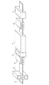
図1に本発明に係る鋼板の製造に好適な設備の一例を示す。鋼板搬送ライン1には上流から下流側に向かって熱間圧延機2、高衝突圧デスケーリング装置3、加速冷却装置4、誘導加熱装置7を配置する。また、デスケーリング装置3の前(上流側)に熱間矯正機5を設置することもできる。熱間矯正機で鋼板の形状を改善することにより、噴射流の衝突圧を増大させることができるため、低コストでより効率的にデスケーリングを行うことができる。一方、誘導加熱装置7の前(上流側)に熱間矯正装置6を設置することもできる。熱間矯正機により鋼板の形状を改善することにより、たとえば、大きな反りを有する鋼板が誘導加熱装置に衝突するような事故を避けることができるばかりでなく、誘導加熱時の温度の均一性が改善されるので、設備の安全性および材質均一性を向上させることができる。
室温まで冷却;
本発明の再加熱温度では、その後の冷却過程により鋼板の材質や形状に影響を与えない。そのため、再加熱後の鋼板を室温まで冷却するための冷却手段は、例えば、空冷によればよい。放冷してもよいし、また、鋼板に空気を吹き付けて積極的に空冷してもよい。これ以外に、水冷や、その他の手段でもかまわない。
FIG. 1 shows an example of equipment suitable for manufacturing a steel sheet according to the present invention. A
Cooling to room temperature;
The reheating temperature of the present invention does not affect the material and shape of the steel sheet by the subsequent cooling process. Therefore, the cooling means for cooling the steel plate after reheating to room temperature may be air cooling, for example. It may be allowed to cool, or may be actively air-cooled by blowing air onto the steel plate. Other than this, water cooling or other means may be used.
以上の再加熱熱処理の後、空冷により室温まで冷却して得られた厚鋼板を、冷間で管状に成形する。 After the above reheating heat treatment, the thick steel plate obtained by cooling to room temperature by air cooling is formed into a tubular shape in the cold.
鋼管の成形方法は、UOEプロセスやプレスベンド等の冷間成形によって鋼管形状に成形する。その後、シーム溶接するが、このときの溶接方法は十分な継手強度及び継手靱性が得られる方法ならいずれの方法でもよいが、優れた溶接品質と製造能率の点からサブマージアーク溶接を用いることが好ましい。本発明では、その突合せ部を2層以上の溶接によって接合し、拡管した溶接鋼管を対象とする。突合せ部を2層以上溶接することにより、溶接入熱の過度な上昇による靱性の劣化を防ぎやすく、また、溶接ビードについても良好な外観形状が安定して得られるためである。突き合せ部の溶接を行った後に、溶接残留応力の除去と鋼管真円度の向上のため、拡管を行う。以下、拡管率について説明する。 The steel pipe is formed into a steel pipe shape by cold forming such as UOE process or press bend. Thereafter, seam welding is performed, and any welding method can be used as long as sufficient joint strength and joint toughness can be obtained, but it is preferable to use submerged arc welding in terms of excellent welding quality and production efficiency. . The present invention is directed to a welded steel pipe in which the butt portion is joined by welding of two or more layers and expanded. By welding two or more butt portions, it is easy to prevent deterioration of toughness due to an excessive increase in welding heat input, and a good appearance shape can be stably obtained with respect to the weld bead. After welding the butt, pipe expansion is performed to remove residual welding stress and improve the roundness of the steel pipe. Hereinafter, the tube expansion rate will be described.
拡管率: 0.5〜1.1%
一般に厚肉高強度UOE鋼管は、0.9〜1.2%程度の範囲の拡管率で造管を行う。拡管率は、耐圧潰性を確保する上で重要な因子であり、拡管率を低くするほど圧縮強度が上昇するが、真円度が低下する。一方で、拡管率を高くするほど真円度は高くなるが、圧縮強度は下がり、さらにはダイスによる鋼管の傷つきが問題になる。拡管率を0.5%より小さくしても圧縮強度上昇効果はあまり期待できないので、下限を0.5%とする。一方で、本発明では、管厚および管周方向の硬さを均一化することによって成形性を著しく向上させているため、拡管率が低くても、所望の真円度を得ることができる。真円度は拡管率が1.1を超える拡管率増加による真円度向上効果が飽和するため、上限を1.1%とする。以上、規定した拡管率0.5〜1.1%の範囲で造管すれば、優れた耐圧潰性能が得られる。また、より好ましくは0.5〜1.0%である。
Tube expansion rate: 0.5-1.1%
In general, a thick-walled and high-strength UOE steel pipe is formed at a pipe expansion rate in the range of about 0.9 to 1.2%. The tube expansion rate is an important factor in securing the crushing resistance. The lower the tube expansion rate, the higher the compressive strength, but the lower the roundness. On the other hand, the higher the tube expansion rate, the higher the roundness, but the compressive strength decreases, and the steel pipe is damaged by a die. Even if the tube expansion rate is less than 0.5%, the compression strength increase effect cannot be expected so much, so the lower limit is made 0.5%. On the other hand, in the present invention, since the formability is remarkably improved by making the tube thickness and the hardness in the tube circumferential direction uniform, a desired roundness can be obtained even if the tube expansion rate is low. The upper limit of the roundness is 1.1% because the roundness improvement effect due to the increase in the pipe expansion rate exceeding 1.1 is saturated. As described above, excellent pipe crushing performance can be obtained if the pipe is formed in the range of the specified expansion ratio of 0.5 to 1.1%. Moreover, More preferably, it is 0.5 to 1.0%.
表1に示す化学成分の鋼を連続鋳造法によりスラブとし、加熱したスラブを熱間圧延により圧延した後、加速冷却装置直前で高衝突圧デスケーリングを行い、5秒以内に水冷型の冷却設備を用いて加速冷却を行った。加速冷却は図1に示した設備を用いて行い、1段目の加速冷却終了後、20秒以内に、2段目の加速冷却を開始し、加速冷却終了後にただちに誘導加熱により急速加熱を行い、その後空冷することにより、厚鋼板を製造した。製造した鋼板をUOE成形によって造管した。突合せ部の溶接は、内面及び外面について各1層のサブマージアーク溶接により実施した。なお、Oプレスの圧縮率はすべて0.3%とした。以上の方法で製造した溶接鋼管の製造方法の詳細を表2に示す。なお、加熱温度は鋼板全体の平均温度とし、圧延終了温度および冷却開始温度、表層冷却停止温度は鋼板表面温度を、誘導加熱による表層加熱温度は鋼板表層温度を、板平均温度および鋼板平均冷却速度は、加熱パターンと実績表層加熱温度より熱伝導計算により計算した。 Steel with the chemical composition shown in Table 1 is made into a slab by continuous casting, and the heated slab is rolled by hot rolling, followed by high impact pressure descaling just before the accelerated cooling device, and water-cooled cooling equipment within 5 seconds Was used for accelerated cooling. Accelerated cooling is performed using the equipment shown in FIG. 1, and after the first stage of accelerated cooling is completed, the second stage of accelerated cooling is started within 20 seconds, and immediately after the completion of accelerated cooling, rapid heating is performed by induction heating. Then, a thick steel plate was produced by air cooling. The manufactured steel plate was piped by UOE forming. The welding of the butt portion was performed by submerged arc welding of one layer on each of the inner surface and the outer surface. In addition, the compression rate of O press was 0.3%. Table 2 shows the details of the manufacturing method of the welded steel pipe manufactured by the above method. The heating temperature is the average temperature of the entire steel sheet, the rolling end temperature and cooling start temperature, the surface layer cooling stop temperature is the steel sheet surface temperature, the surface heating temperature by induction heating is the steel sheet surface temperature, the plate average temperature and the steel sheet average cooling rate. Was calculated from the heating pattern and the actual surface heating temperature by heat conduction calculation.

真円度は、鋼管外径を管周方向に6箇所以上測定し、その最大値/最小値を求めることで算出した。真円度(Dmax−Dmin)の目標値は、請求項3に記載の範囲とした。
長手方向の測定位置は、両管端および管内部2000mm(管長が12000mmなので管内部は5箇所)の5点の合計7箇所測定し、その最も大きい値を評価に用いた。測定は、管端はノギスにより、管内部は鋼管を回転させ接触式のプロフィル計で測定した。
The roundness was calculated by measuring the outer diameter of the steel pipe at six or more locations in the pipe circumferential direction and obtaining the maximum value / minimum value. The target value of roundness (Dmax−Dmin) is set in the range described in
For the measurement position in the longitudinal direction, a total of 7 points were measured including 5 points of both tube ends and 2000 mm inside the tube (5 mm inside the tube because the tube length was 12000 mm), and the largest value was used for evaluation. The measurement was performed with a caliper at the end of the tube and with a contact-type profile meter while rotating the steel tube inside the tube.
鋼管のミクロ組織の分率は、表層から1mm位置および管厚中心位置について400倍で組織観察した10枚の光学顕微鏡写真の画像解析からフェライト相とベイナイト相の合計の面積分率を平均して求めた。管厚中央に関しては中央偏析部を除外した。M−A体積分率は、表層から1mm位置、管厚内表面から1/4位置、管厚中央について2000倍で組織観察した5枚のSEM(走査型電子顕微鏡)写真の画像解析から面積分率を平均して求め、鋼管中に均一に第2相が分散していると仮定して、前記面積分率の値が体積分率の値に等しいものとみなした。ミクロ組織の目標形態は、本発明の請求項の範囲とした。 The fraction of the microstructure of the steel pipe is obtained by averaging the total area fraction of the ferrite phase and the bainite phase from image analysis of 10 optical micrographs observed at 400 times the 1 mm position and the tube thickness center position from the surface layer. Asked. The central segregation part was excluded for the tube thickness center. The M-A volume fraction was determined from the image analysis of five SEM (scanning electron microscope) photographs of the structure observed at a magnification of 2000 times about 1 mm from the surface layer, 1/4 position from the inner surface of the tube thickness, and the center of the tube thickness. The rate was averaged and the area fraction value was considered equal to the volume fraction value, assuming that the second phase was uniformly dispersed in the steel pipe. The target form of the microstructure is within the scope of the claims of the present invention.
管周方向の硬さ分布は、鋼管のシーム溶接部を起点とした管周方向位置として、40〜320°位置の表面から1mmおよび裏面から1mm位置を20mmピッチで測定し、その最低値および最高値の差を求めた。管厚方向の硬さ分布は、鋼管90°位置について1mmピッチで表層から1mmと裏面から1mmの位置にかけて測定し、その最低値と最大値の差を求めた。鋼管最大硬さは以上で測定した硬さ結果の最大値を用いた。なお、硬さをすべてビッカース硬さ試験機で10kgf(98N)の荷重で測定した。 Hardness distribution in the pipe circumferential direction is measured at a pitch of 1 mm from the front surface at 40 to 320 ° and a 1 mm position from the back surface at a 20 mm pitch, starting from the seam welded portion of the steel pipe. The difference in values was determined. The hardness distribution in the tube thickness direction was measured at a 1 mm pitch from the surface layer to 1 mm from the surface and 1 mm from the back surface at a 90 ° position of the steel pipe, and the difference between the minimum value and the maximum value was obtained. The maximum value of the hardness result measured above was used for the maximum hardness of the steel pipe. In addition, all the hardness was measured with the load of 10 kgf (98N) with the Vickers hardness tester.
鋼管の引張降伏応力および引張強度は、鋼管90°位置の鋼管周方向から全厚引張試験片を採取し、求めた。引張強度の目標値は、520MPa以上である。圧縮降伏応力は、鋼管180°位置の内表面から1mmの位置からASTM E9準拠の直径20mm、長さ60mmの円筒試験片を採取し、0.5%における応力を求めた。圧縮降伏応力の目標値は、引張降伏応力の80%以上とした。DWTT(Drop Weight Tear Test:落重引裂試験)特性は、鋼管周方向から採取した19mmのDWTT試験片を用いて−17℃で試験を行い、破面率(SA(%))を求めた。試験は各2本実施し、その平均値が85%以上になることを目標とした。 The tensile yield stress and tensile strength of the steel pipe were obtained by collecting a full thickness tensile test piece from the circumferential direction of the steel pipe at the 90 ° position. The target value of tensile strength is 520 MPa or more. For the compressive yield stress, a cylindrical test piece having a diameter of 20 mm and a length of 60 mm in accordance with ASTM E9 was taken from a position 1 mm from the inner surface of the steel pipe 180 ° position, and the stress at 0.5% was obtained. The target value of compressive yield stress was 80% or more of the tensile yield stress. DWTT (Drop Weight Tear Test) characteristics were tested at −17 ° C. using a 19 mm DWTT specimen taken from the circumferential direction of the steel pipe, and the fracture surface ratio (SA (%)) was obtained. Two tests were carried out each, and the target was an average value of 85% or more.
耐圧潰性は、DNV−OS−F101で規定されている下記の外圧による圧潰抵抗の式(8)〜(12)を用いて圧潰抵抗pcを評価した。 Crush resistance was evaluated crush resistance p c with DNV-OS-F101 defined in external pressure of crushing resistance by the following formula (8) to (12).
ここで、αU=0.96、αfab=1.00、E=206000MPa、ν=0.3、t=管厚(mm)、D=外径(mm)、Dmax−Dmin=真円度(mm)、YS=常温での圧縮降伏応力(MPa)である。圧潰抵抗の目標値は、式(8)〜(12)に引張降伏応力、f0=0.0050、αfab=0.85を代入して計算される値を基準値として1.13倍以上になることとした。 Here, α U = 0.96, α fab = 1.00, E = 206000 MPa, ν = 0.3, t = tube thickness (mm), D = outer diameter (mm), Dmax−Dmin = roundness (Mm), YS = compressive yield stress (MPa) at room temperature. The target value of the crush resistance is 1.13 times or more with a value calculated by substituting the tensile yield stress, f 0 = 0.0050, α fab = 0.85 into the equations (8) to (12). Decided to become.
なお、DNV−OS−F101では、5%以下の真円度は通常は全長に亘って保障できないため式(8)〜(12)による評価には用いず、f0=0.05として評価することになっているが、本発明では、管内部についても真円度を保証しているため、式(8)〜(12)式が成り立つものとした。なお、FEMによる数値計算により、f0<0.05においても式(8)〜式(12)が成り立つことは、別途確認している。 In DNV-OS-F101, since a roundness of 5% or less cannot normally be ensured over the entire length, it is not used in the evaluation according to the equations (8) to (12), and is evaluated as f 0 = 0.05. However, in the present invention, since the roundness is guaranteed also inside the pipe, the expressions (8) to (12) are established. In addition, it has been confirmed separately that the equations (8) to (12) hold even when f 0 <0.05 by numerical calculation by FEM.
HIC特性は、NACE Standard TM0284−2003に基づいて、各3個のサンプルを採取して、pHが約3の硫化水素を飽和させた5%NaCl+0.5%CH3COOH水溶液中に試験片を96時間浸漬した後、超音波探傷により試験片全面の割れの有無を調査し、割れ面積率(CAR)で評価した。ここで、それぞれの鋼板の最大値をその鋼板のCARとしてCAR≦5%を合格とした。SSC特性は、NACE Standard TM0177−2005に基づいて、内表面側から採取した厚さ5mmの3点曲げ型サンプルに、負荷応力を母材の降伏応力の90%かけて、pHが約3の硫化水素を飽和させたNaCl+0.5%CH3COOH水溶液中に試験片を720時間浸漬して破断するか否か評価した。試験は3本ずつ行い、3本とも破断しなかった場合は、No crack、1本でも破断した場合は、Crackと評価した。本試験で、3本とも破断しなかった場合は、耐サワー性能が優れると評価できる。 Based on NACE Standard TM0284-2003, the HIC characteristics were determined by taking three samples each and placing 96 specimens in a 5% NaCl + 0.5% CH 3 COOH aqueous solution saturated with hydrogen sulfide having a pH of about 3. After immersion for a period of time, the presence or absence of cracks on the entire surface of the test piece was investigated by ultrasonic flaw detection, and evaluated by a crack area ratio (CAR). Here, the maximum value of each steel plate was regarded as the CAR of the steel plate, and CAR ≦ 5% was regarded as acceptable. Based on NACE Standard TM0177-2005, the SSC characteristics were obtained by applying a load stress of 90% of the yield stress of the base material to a 3-point bendable sample with a thickness of 5 mm taken from the inner surface side, and having a pH of about 3 It was evaluated whether or not the test piece was immersed in a NaCl + 0.5% CH 3 COOH aqueous solution saturated with hydrogen for 720 hours to break. The test was performed three by three, and when all three were not broken, No crack was evaluated, and when even one was broken, it was evaluated as Crack. It can be evaluated that the sour resistance is excellent when all three pieces are not broken in this test.
表3に表2の製造方法で得られた溶接鋼管のミクロ組織形態と機械的特性を示す。本発明例の請求範囲内の溶接鋼管はいずれも、ラインパイプとして必要とされる強度、DWTT性能を満たしつつ、優れた耐圧潰性、耐サワー性能を両立していることがわかる。一方で、本発明の請求範囲外の溶接鋼管は、それらのいずれかの特性を満たしていない。 Table 3 shows the microstructure and mechanical properties of the welded steel pipe obtained by the manufacturing method shown in Table 2. It can be seen that all of the welded steel pipes within the scope of the claims of the present invention have both excellent crushing resistance and sour resistance while satisfying the strength and DWTT performance required for a line pipe. On the other hand, the welded steel pipe outside the scope of the present invention does not satisfy any of these characteristics.
1 鋼板搬送ライン
2 熱間圧延機
3 高衝突圧デスケーリング装置
4 加速冷却装置と
5 熱間矯正装置
6 誘導加熱装置
7 熱間矯正装置
DESCRIPTION OF SYMBOLS 1 Steel
Claims (4)
質量%で、
C: 0.02〜0.08%
Si: 0.01〜0.50%
Mn: 0.5〜1.5%
P: 0.010%以下
S: 0.001%以下
Al: 0.06%以下
Nb: 0.002〜0.100%
Ca: 0.0005〜0.0040%
O: 0.0030%以下
を含有し、さらに、
Cu: 1.0%以下
Ni: 1.0%以下
Cr: 1.0%以下
Mo: 0.5%以下
の中から選ばれる1種以上を含有し、
さらに、式(1)で規定されるCeqが0.30以上、
式(2)で規定されるPHICが1.00以下、
式(3)で規定されるACRが1.00〜6.00であり、
残部Feおよび不可避的不純物からなり、
母材表層部の金属組織が上部ベイナイトであるか、又はフェライト及び上部ベイナイトであり、
母材管厚中心部の金属組織が上部ベイナイト単相であり、
管厚全域で島状マルテンサイト(M−A)の体積分率が1.0%以下、
かつ、管厚方向同位置における管周方向の硬度差の最大値が30以下、
管周方向同位置における管厚方向の硬度差の最大値が30以下、
表層硬さの最大値が230以下である
ことを特徴とする耐圧潰性および耐サワー性に優れた高強度ラインパイプ。
Ceq=C+Mn/6+(Cu+Ni)/15+(Cr+Mo+V)/5 式(1)
PHIC=4.46C+2.37Mn/6+(1.18Cr+1.95Mo+1.74V)/5+(1.74Cu+1.7Ni)/15+22.36P 式(2)
ACR=(Ca−(0.18+130Ca)O)/1.25S 式(3)
ここで、各式の右辺の元素記号はそれぞれの含有量(質量%)を表わし、含有しない場合は0とする。 A welded steel pipe in which a base material made of a thick steel plate is formed into a tubular shape, and a butt portion thereof is joined by welding of two or more layers,
% By mass
C: 0.02 to 0.08%
Si: 0.01 to 0.50%
Mn: 0.5 to 1.5%
P: 0.010% or less S: 0.001% or less Al: 0.06% or less Nb: 0.002 to 0.100%
Ca: 0.0005 to 0.0040%
O: contains 0.0030% or less,
Cu: 1.0% or less Ni: 1.0% or less Cr: 1.0% or less Mo: containing at least one selected from 0.5% or less,
Furthermore, Ceq defined by the formula (1) is 0.30 or more,
PHIC defined by the formula (2) is 1.00 or less,
ACR defined by equation (3) is 1.00 to 6.00,
The balance Fe and inevitable impurities,
The metal structure of the base material surface layer portion is upper bainite, or ferrite and upper bainite,
The metal structure of the base metal tube thickness center is the upper bainite single phase,
The volume fraction of island martensite (MA) is 1.0% or less throughout the tube thickness,
And the maximum value of the hardness difference in the pipe circumferential direction at the same position in the pipe thickness direction is 30 or less,
The maximum value of the hardness difference in the pipe thickness direction at the same position in the pipe circumferential direction is 30 or less,
A high-strength line pipe excellent in crushing resistance and sour resistance, characterized in that the maximum surface hardness is 230 or less.
Ceq = C + Mn / 6 + (Cu + Ni) / 15 + (Cr + Mo + V) / 5 Formula (1)
PHIC = 4.46C + 2.37Mn / 6 + (1.18Cr + 1.95Mo + 1.74V) / 5 + (1.74Cu + 1.7Ni) /15+22.36P Formula (2)
ACR = (Ca− (0.18 + 130Ca) O) /1.25S Formula (3)
Here, the element symbol on the right side of each formula represents the content (% by mass), and is 0 when not contained.
V: 0.005〜0.100%
Ti: 0.005〜0.050%
Mg: 0.0005〜0.0040%
の中から選ばれる1種以上を含有することを特徴とする請求項1記載の耐圧潰性および耐サワー性に優れた高強度ラインパイプ。 Furthermore, in mass%,
V: 0.005 to 0.100%
Ti: 0.005 to 0.050%
Mg: 0.0005 to 0.0040%
The high-strength line pipe excellent in crushing resistance and sour resistance according to claim 1, comprising at least one selected from the group consisting of:
D/t0.6≦135の場合 Dmax−Dmin≦3.0 式(4)
D/t0.6>135の場合 Dmax−Dmin≦0.04D/t0.6−1.4 式(5)
ここで、D: 公称外径(mm)、t: 管厚(mm)、Dmax−Dmin: 真円度(mm)、Dmax:測定最大外径(mm)、Dmin:測定最小外径(mm)である。 The high-strength line pipe with excellent crushing resistance and sour resistance according to claim 1 or 2, wherein the roundness satisfies the following formula (4) or (5).
In the case of D / t 0.6 ≦ 135 Dmax−Dmin ≦ 3.0 Formula (4)
When D / t 0.6 > 135 Dmax−Dmin ≦ 0.04 D / t 0.6 −1.4 Formula (5)
Here, D: nominal outer diameter (mm), t: tube thickness (mm), Dmax-Dmin: roundness (mm), Dmax: maximum measured outer diameter (mm), Dmin: minimum measured outer diameter (mm) It is.
900℃以下の累積圧下率を30〜90%とし圧延終了温度を(Ar3−10℃)以上とした熱間圧延を行った後、
加速冷却の直前に鋼板表面での噴射流衝突圧が1MPa以上のデスケーリングを行い、
その後、鋼板表層温度が(Ar3−80℃)以上の温度域から、鋼板表層冷却速度が10℃/s以上100℃/s以下で、
鋼板表層温度が300℃以上600℃以下、なおかつ鋼板平均温度が630℃以上の温度域まで、式(6)を満たす条件で1段目の加速冷却を行い、
続いて、鋼板平均冷却速度が10℃/s以上で鋼板平均温度が300℃以上600℃以下の温度域まで2段目の加速冷却を行い
その後、鋼板平均温度を冷却停止温度以上かつ400〜600℃の温度域に再加熱し、室温まで冷却して得られた厚鋼板を、冷間で管状に成形し、
突合せ部を溶接し鋼管とした後、
さらに、0.5〜1.1%の拡管率で拡管を行うことによって製造する
ことを特徴とする請求項1〜3のいずれか1項に記載の耐圧潰性および耐サワー性に優れた高強度ラインパイプの製造方法。
(700−T)/V≧3 式(6)
ここで、T: 1段目の加速冷却の鋼板表層冷却停止温度(℃)、V: 1段目の加速冷却の鋼板表層冷却速度(℃/s)である。 After heating the steel material to 900-1200 ° C,
After performing hot rolling with a cumulative rolling reduction of 900 ° C. or lower at 30 to 90% and a rolling end temperature of (Ar 3 −10 ° C.) or higher,
Immediately before accelerated cooling, descaling with a jet collision pressure on the steel sheet surface of 1 MPa or more,
Thereafter, the steel sheet surface temperature (Ar 3 -80 ℃) above temperature range, the steel sheet surface layer cooling rate is 10 ° C. / s or higher 100 ° C. / s or less,
The steel plate surface layer temperature is 300 ° C. or higher and 600 ° C. or lower, and the steel plate average temperature is 630 ° C. or higher.
Subsequently, the second stage accelerated cooling is performed until the steel sheet average cooling rate is 10 ° C./s or higher and the steel plate average temperature is 300 ° C. or higher and 600 ° C. or lower, and then the steel plate average temperature is set to the cooling stop temperature or higher and 400 to 600. Reheated to a temperature range of ℃, cooled to room temperature, formed into a tubular shape in the cold,
After welding the butt to make a steel pipe,
Furthermore, it manufactures by performing a pipe expansion with a pipe expansion rate of 0.5 to 1.1%, The high excellent in crushing resistance and sour resistance of any one of Claims 1-3 characterized by the above-mentioned. Strength line pipe manufacturing method.
(700-T) / V ≧ 3 Formula (6)
Here, T: steel plate surface layer cooling stop temperature (° C.) for the first stage accelerated cooling, and V: steel sheet surface layer cooling rate (° C./s) for the first stage accelerated cooling.
Priority Applications (1)
| Application Number | Priority Date | Filing Date | Title |
|---|---|---|---|
| JP2011115449A JP5751012B2 (en) | 2011-05-24 | 2011-05-24 | Manufacturing method of high-strength line pipe with excellent crush resistance and sour resistance |
Applications Claiming Priority (1)
| Application Number | Priority Date | Filing Date | Title |
|---|---|---|---|
| JP2011115449A JP5751012B2 (en) | 2011-05-24 | 2011-05-24 | Manufacturing method of high-strength line pipe with excellent crush resistance and sour resistance |
Publications (2)
| Publication Number | Publication Date |
|---|---|
| JP2012241273A true JP2012241273A (en) | 2012-12-10 |
| JP5751012B2 JP5751012B2 (en) | 2015-07-22 |
Family
ID=47463305
Family Applications (1)
| Application Number | Title | Priority Date | Filing Date |
|---|---|---|---|
| JP2011115449A Active JP5751012B2 (en) | 2011-05-24 | 2011-05-24 | Manufacturing method of high-strength line pipe with excellent crush resistance and sour resistance |
Country Status (1)
| Country | Link |
|---|---|
| JP (1) | JP5751012B2 (en) |
Cited By (15)
| Publication number | Priority date | Publication date | Assignee | Title |
|---|---|---|---|---|
| JP2012241274A (en) * | 2011-05-24 | 2012-12-10 | Jfe Steel Corp | High strength linepipe superior in collapse resistance and sour resistance, and method for producing the same |
| KR101560941B1 (en) | 2013-12-24 | 2015-10-15 | 주식회사 포스코 | Hot rolled steel sheet for pipe having excellent strength and expending property and method for manufacturing the same |
| WO2016051727A1 (en) * | 2014-09-30 | 2016-04-07 | Jfeスチール株式会社 | Welded steel pipe, steel plate, and manufacturing method therefor |
| JP2017078212A (en) * | 2015-10-21 | 2017-04-27 | 新日鐵住金株式会社 | Low yield ratio steel sheet and method for producing the same |
| JP6288390B1 (en) * | 2017-03-29 | 2018-03-07 | 新日鐵住金株式会社 | AZROLL ERW Steel Pipe for Line Pipe |
| JP2020012168A (en) * | 2018-07-19 | 2020-01-23 | 日本製鉄株式会社 | Thick steel sheet for sour resistant linepipe, and manufacturing method therefor |
| JP2020059887A (en) * | 2018-10-10 | 2020-04-16 | 日本製鉄株式会社 | Electroseamed steel pipe for oil wells and method for producing the same |
| WO2020111863A1 (en) * | 2018-11-30 | 2020-06-04 | 주식회사 포스코 | Ultrahigh-strength steel having excellent cold workability and ssc resistance, and manufacturing method therefor |
| JP2020200497A (en) * | 2019-06-07 | 2020-12-17 | 日本製鉄株式会社 | Steel plate and steel pipe for line pipe |
| JPWO2021144953A1 (en) * | 2020-01-17 | 2021-07-22 | ||
| EP3950997A4 (en) * | 2019-03-28 | 2022-05-18 | JFE Steel Corporation | Steel material for line pipes and method for manufacturing same, and line pipe and method for manufacturing same |
| CN115210396A (en) * | 2020-03-04 | 2022-10-18 | 日本制铁株式会社 | Steel pipe and steel plate |
| JP7397318B2 (en) | 2020-04-23 | 2023-12-13 | 日本製鉄株式会社 | Steel plate manufacturing method, steel pipe manufacturing method, steel plate manufacturing equipment and program |
| JP7440740B2 (en) | 2019-12-06 | 2024-02-29 | 日本製鉄株式会社 | Steel plate for tanks |
| JP7448803B2 (en) | 2020-04-23 | 2024-03-13 | 日本製鉄株式会社 | Steel plate manufacturing method, steel pipe manufacturing method, steel plate manufacturing equipment and program |
Citations (31)
| Publication number | Priority date | Publication date | Assignee | Title |
|---|---|---|---|---|
| US5352304A (en) * | 1992-11-16 | 1994-10-04 | Allegheny Ludlum Corporation | High strength low alloy steel |
| JPH09194991A (en) * | 1996-01-22 | 1997-07-29 | Sumitomo Metal Ind Ltd | Welded steel tube excellent in sour resistance and carbon dioxide gas corrosion resistance |
| JPH10265844A (en) * | 1997-03-25 | 1998-10-06 | Sumitomo Metal Ind Ltd | Low yield ratio steel and its production |
| JP2000160245A (en) * | 1998-12-02 | 2000-06-13 | Nkk Corp | Production of high strength steel excellent in hic resistance |
| JP2002129281A (en) * | 2000-10-23 | 2002-05-09 | Nippon Steel Corp | High tensile strength steel for welding structure excellent in fatigue resistance in weld zone and its production method |
| JP2002363644A (en) * | 2001-06-11 | 2002-12-18 | Nippon Steel Corp | Method for manufacturing high-tensile steel with excellent toughness and fatigue strength |
| JP2005146414A (en) * | 2003-10-20 | 2005-06-09 | Jfe Steel Kk | Expansive seamless steel pipe for use in oil well and method for production thereof |
| JP2005205477A (en) * | 2004-01-26 | 2005-08-04 | Nippon Steel Corp | Hot-press-forming method with excellent productivity and automotive member |
| JP2008056962A (en) * | 2006-08-30 | 2008-03-13 | Jfe Steel Kk | Steel sheet for high strength line pipe which is excellent in resistance to crack induced by hydrogen and has small reduction in yield stress due to bauschinger effect, and manufacturing method therefor |
| JP2008121036A (en) * | 2006-11-09 | 2008-05-29 | Jfe Steel Kk | Method for producing high-strength and high-toughness steel sheet |
| JP2008156754A (en) * | 2006-11-30 | 2008-07-10 | Nippon Steel Corp | Weld steel pipe with excellent low-temperature toughness for high-strength line pipe and process for producing the same |
| JP2008163455A (en) * | 2006-12-04 | 2008-07-17 | Nippon Steel Corp | Weld steel pipe with excellent low-temperature toughness for high-strength thick-walled line pipe and process for producing the same |
| JP2009041083A (en) * | 2007-08-10 | 2009-02-26 | Sumitomo Metal Ind Ltd | High-strength thick steel plate having excellent brittle-crack arrestability, and method for producing the same |
| JP2009052137A (en) * | 2007-07-31 | 2009-03-12 | Jfe Steel Kk | Steel sheet for high strength sour resistant line pipe, method for producing the same, and steel pipe |
| JP2009133005A (en) * | 2007-11-07 | 2009-06-18 | Jfe Steel Corp | Steel plate for line pipe and steel pipe |
| JP2009221534A (en) * | 2008-03-15 | 2009-10-01 | Jfe Steel Corp | Steel sheet for line pipe |
| JP2009221533A (en) * | 2008-03-15 | 2009-10-01 | Jfe Steel Corp | High strength steel pipe having excellent internal pressure fracture resistance, and method for producing the same |
| JP2009275261A (en) * | 2008-05-15 | 2009-11-26 | Jfe Steel Corp | Welded steel-pipe superior in crushing resistance and manufacturing method therefor |
| JP2010024497A (en) * | 2008-07-18 | 2010-02-04 | Kobe Steel Ltd | High strength cold rolled steel sheet having excellent elongation and stretch-flangeability |
| JP2010084171A (en) * | 2008-09-30 | 2010-04-15 | Jfe Steel Corp | High toughness welded steel pipe having high crushing strength and method for producing the same |
| JP2010196164A (en) * | 2009-01-30 | 2010-09-09 | Jfe Steel Corp | Thick, high-tension, hot-rolled steel sheet excellent in low-temperature toughness, and manufacturing method therefor |
| WO2010110473A1 (en) * | 2009-03-25 | 2010-09-30 | Jfeスチール株式会社 | Steel plate manufacturing equipment and method of manufacturing |
| JP2010236047A (en) * | 2009-03-31 | 2010-10-21 | Jfe Steel Corp | Steel sheet having high toughness and high tensile strength and excellent strength-elongation balance, and method for manufacturing the same |
| JP2010236046A (en) * | 2009-03-31 | 2010-10-21 | Jfe Steel Corp | Steel sheet having high toughness, high tensile strength and excellent strength-elongation balance, and method for manufacturing the same |
| JP2010247227A (en) * | 2009-03-25 | 2010-11-04 | Jfe Steel Corp | Equipment and method for manufacturing thick steel plate |
| JP2011115447A (en) * | 2009-12-04 | 2011-06-16 | Japana Co Ltd | Snowboard and method for manufacturing the same |
| JP2011115450A (en) * | 2009-12-04 | 2011-06-16 | Toyota Central R&D Labs Inc | Apparatus, method, and program for determining aimless state |
| JP2011115446A (en) * | 2009-12-04 | 2011-06-16 | Jms Co Ltd | Connecting structure of plunger rod with gasket |
| JP2012241274A (en) * | 2011-05-24 | 2012-12-10 | Jfe Steel Corp | High strength linepipe superior in collapse resistance and sour resistance, and method for producing the same |
| JP2012241270A (en) * | 2011-05-24 | 2012-12-10 | Jfe Steel Corp | High strength sour-resistant linepipe superior in collapse resistance and method for producing the same |
| JP2012241271A (en) * | 2011-05-24 | 2012-12-10 | Jfe Steel Corp | High strength sour-resistant linepipe superior in collapse resistance and method for producing the same |
-
2011
- 2011-05-24 JP JP2011115449A patent/JP5751012B2/en active Active
Patent Citations (32)
| Publication number | Priority date | Publication date | Assignee | Title |
|---|---|---|---|---|
| US5352304A (en) * | 1992-11-16 | 1994-10-04 | Allegheny Ludlum Corporation | High strength low alloy steel |
| JPH09194991A (en) * | 1996-01-22 | 1997-07-29 | Sumitomo Metal Ind Ltd | Welded steel tube excellent in sour resistance and carbon dioxide gas corrosion resistance |
| JPH10265844A (en) * | 1997-03-25 | 1998-10-06 | Sumitomo Metal Ind Ltd | Low yield ratio steel and its production |
| JP2000160245A (en) * | 1998-12-02 | 2000-06-13 | Nkk Corp | Production of high strength steel excellent in hic resistance |
| JP2002129281A (en) * | 2000-10-23 | 2002-05-09 | Nippon Steel Corp | High tensile strength steel for welding structure excellent in fatigue resistance in weld zone and its production method |
| JP2002363644A (en) * | 2001-06-11 | 2002-12-18 | Nippon Steel Corp | Method for manufacturing high-tensile steel with excellent toughness and fatigue strength |
| JP2005146414A (en) * | 2003-10-20 | 2005-06-09 | Jfe Steel Kk | Expansive seamless steel pipe for use in oil well and method for production thereof |
| JP2005205477A (en) * | 2004-01-26 | 2005-08-04 | Nippon Steel Corp | Hot-press-forming method with excellent productivity and automotive member |
| JP2008056962A (en) * | 2006-08-30 | 2008-03-13 | Jfe Steel Kk | Steel sheet for high strength line pipe which is excellent in resistance to crack induced by hydrogen and has small reduction in yield stress due to bauschinger effect, and manufacturing method therefor |
| JP2008121036A (en) * | 2006-11-09 | 2008-05-29 | Jfe Steel Kk | Method for producing high-strength and high-toughness steel sheet |
| JP2008156754A (en) * | 2006-11-30 | 2008-07-10 | Nippon Steel Corp | Weld steel pipe with excellent low-temperature toughness for high-strength line pipe and process for producing the same |
| JP2008163455A (en) * | 2006-12-04 | 2008-07-17 | Nippon Steel Corp | Weld steel pipe with excellent low-temperature toughness for high-strength thick-walled line pipe and process for producing the same |
| JP2009052137A (en) * | 2007-07-31 | 2009-03-12 | Jfe Steel Kk | Steel sheet for high strength sour resistant line pipe, method for producing the same, and steel pipe |
| JP2009041083A (en) * | 2007-08-10 | 2009-02-26 | Sumitomo Metal Ind Ltd | High-strength thick steel plate having excellent brittle-crack arrestability, and method for producing the same |
| JP2009133005A (en) * | 2007-11-07 | 2009-06-18 | Jfe Steel Corp | Steel plate for line pipe and steel pipe |
| US20100326559A1 (en) * | 2007-11-07 | 2010-12-30 | Jfe Steel Corporation | Steel plate and steel pipe for line pipes |
| JP2009221533A (en) * | 2008-03-15 | 2009-10-01 | Jfe Steel Corp | High strength steel pipe having excellent internal pressure fracture resistance, and method for producing the same |
| JP2009221534A (en) * | 2008-03-15 | 2009-10-01 | Jfe Steel Corp | Steel sheet for line pipe |
| JP2009275261A (en) * | 2008-05-15 | 2009-11-26 | Jfe Steel Corp | Welded steel-pipe superior in crushing resistance and manufacturing method therefor |
| JP2010024497A (en) * | 2008-07-18 | 2010-02-04 | Kobe Steel Ltd | High strength cold rolled steel sheet having excellent elongation and stretch-flangeability |
| JP2010084171A (en) * | 2008-09-30 | 2010-04-15 | Jfe Steel Corp | High toughness welded steel pipe having high crushing strength and method for producing the same |
| JP2010196164A (en) * | 2009-01-30 | 2010-09-09 | Jfe Steel Corp | Thick, high-tension, hot-rolled steel sheet excellent in low-temperature toughness, and manufacturing method therefor |
| JP2010247227A (en) * | 2009-03-25 | 2010-11-04 | Jfe Steel Corp | Equipment and method for manufacturing thick steel plate |
| WO2010110473A1 (en) * | 2009-03-25 | 2010-09-30 | Jfeスチール株式会社 | Steel plate manufacturing equipment and method of manufacturing |
| JP2010236046A (en) * | 2009-03-31 | 2010-10-21 | Jfe Steel Corp | Steel sheet having high toughness, high tensile strength and excellent strength-elongation balance, and method for manufacturing the same |
| JP2010236047A (en) * | 2009-03-31 | 2010-10-21 | Jfe Steel Corp | Steel sheet having high toughness and high tensile strength and excellent strength-elongation balance, and method for manufacturing the same |
| JP2011115447A (en) * | 2009-12-04 | 2011-06-16 | Japana Co Ltd | Snowboard and method for manufacturing the same |
| JP2011115450A (en) * | 2009-12-04 | 2011-06-16 | Toyota Central R&D Labs Inc | Apparatus, method, and program for determining aimless state |
| JP2011115446A (en) * | 2009-12-04 | 2011-06-16 | Jms Co Ltd | Connecting structure of plunger rod with gasket |
| JP2012241274A (en) * | 2011-05-24 | 2012-12-10 | Jfe Steel Corp | High strength linepipe superior in collapse resistance and sour resistance, and method for producing the same |
| JP2012241270A (en) * | 2011-05-24 | 2012-12-10 | Jfe Steel Corp | High strength sour-resistant linepipe superior in collapse resistance and method for producing the same |
| JP2012241271A (en) * | 2011-05-24 | 2012-12-10 | Jfe Steel Corp | High strength sour-resistant linepipe superior in collapse resistance and method for producing the same |
Cited By (30)
| Publication number | Priority date | Publication date | Assignee | Title |
|---|---|---|---|---|
| JP2012241274A (en) * | 2011-05-24 | 2012-12-10 | Jfe Steel Corp | High strength linepipe superior in collapse resistance and sour resistance, and method for producing the same |
| KR101560941B1 (en) | 2013-12-24 | 2015-10-15 | 주식회사 포스코 | Hot rolled steel sheet for pipe having excellent strength and expending property and method for manufacturing the same |
| WO2016051727A1 (en) * | 2014-09-30 | 2016-04-07 | Jfeスチール株式会社 | Welded steel pipe, steel plate, and manufacturing method therefor |
| JPWO2016051727A1 (en) * | 2014-09-30 | 2017-04-27 | Jfeスチール株式会社 | Welded steel pipe, thick steel plate and method for producing them |
| JP2017078212A (en) * | 2015-10-21 | 2017-04-27 | 新日鐵住金株式会社 | Low yield ratio steel sheet and method for producing the same |
| JP6288390B1 (en) * | 2017-03-29 | 2018-03-07 | 新日鐵住金株式会社 | AZROLL ERW Steel Pipe for Line Pipe |
| WO2018179169A1 (en) * | 2017-03-29 | 2018-10-04 | 新日鐵住金株式会社 | As-rolled type electric-resistance-welded steel pipe for line pipes |
| CN110088317A (en) * | 2017-03-29 | 2019-08-02 | 日本制铁株式会社 | Spool as-rolled condition electric welded steel pipe |
| JP7155702B2 (en) | 2018-07-19 | 2022-10-19 | 日本製鉄株式会社 | Thick steel plate for sour linepipe and its manufacturing method |
| JP2020012168A (en) * | 2018-07-19 | 2020-01-23 | 日本製鉄株式会社 | Thick steel sheet for sour resistant linepipe, and manufacturing method therefor |
| JP7216902B2 (en) | 2018-10-10 | 2023-02-02 | 日本製鉄株式会社 | ERW steel pipe for oil well and manufacturing method thereof |
| JP2020059887A (en) * | 2018-10-10 | 2020-04-16 | 日本製鉄株式会社 | Electroseamed steel pipe for oil wells and method for producing the same |
| WO2020111863A1 (en) * | 2018-11-30 | 2020-06-04 | 주식회사 포스코 | Ultrahigh-strength steel having excellent cold workability and ssc resistance, and manufacturing method therefor |
| KR20200066512A (en) * | 2018-11-30 | 2020-06-10 | 주식회사 포스코 | Ultra high strength steel material having excellent cold workability and sulfide stress cracking resistance and method of manufacturing the same |
| KR102131538B1 (en) * | 2018-11-30 | 2020-07-08 | 주식회사 포스코 | Ultra high strength steel material having excellent cold workability and sulfide stress cracking resistance and method of manufacturing the same |
| JP7339339B2 (en) | 2018-11-30 | 2023-09-05 | ポスコ カンパニー リミテッド | Ultra-high-strength steel material with excellent cold workability and SSC resistance, and method for producing the same |
| EP3929323A4 (en) * | 2018-11-30 | 2022-01-05 | Posco | Ultrahigh-strength steel having excellent cold workability and ssc resistance, and manufacturing method therefor |
| JP2022510214A (en) * | 2018-11-30 | 2022-01-26 | ポスコ | Ultra-high-strength steel with excellent cold workability and SSC resistance and its manufacturing method |
| EP3950997A4 (en) * | 2019-03-28 | 2022-05-18 | JFE Steel Corporation | Steel material for line pipes and method for manufacturing same, and line pipe and method for manufacturing same |
| JP7335492B2 (en) | 2019-06-07 | 2023-08-30 | 日本製鉄株式会社 | Steel plates and steel pipes for line pipes |
| JP2020200497A (en) * | 2019-06-07 | 2020-12-17 | 日本製鉄株式会社 | Steel plate and steel pipe for line pipe |
| JP7440740B2 (en) | 2019-12-06 | 2024-02-29 | 日本製鉄株式会社 | Steel plate for tanks |
| JPWO2021144953A1 (en) * | 2020-01-17 | 2021-07-22 | ||
| JP7295470B2 (en) | 2020-01-17 | 2023-06-21 | 日本製鉄株式会社 | steel plate and pipe |
| CN114846163A (en) * | 2020-01-17 | 2022-08-02 | 日本制铁株式会社 | Steel plate and steel pipe |
| CN114846163B (en) * | 2020-01-17 | 2023-10-24 | 日本制铁株式会社 | Steel plate and steel pipe |
| WO2021144953A1 (en) * | 2020-01-17 | 2021-07-22 | 日本製鉄株式会社 | Steel sheet and steel pipe |
| CN115210396A (en) * | 2020-03-04 | 2022-10-18 | 日本制铁株式会社 | Steel pipe and steel plate |
| JP7397318B2 (en) | 2020-04-23 | 2023-12-13 | 日本製鉄株式会社 | Steel plate manufacturing method, steel pipe manufacturing method, steel plate manufacturing equipment and program |
| JP7448803B2 (en) | 2020-04-23 | 2024-03-13 | 日本製鉄株式会社 | Steel plate manufacturing method, steel pipe manufacturing method, steel plate manufacturing equipment and program |
Also Published As
| Publication number | Publication date |
|---|---|
| JP5751012B2 (en) | 2015-07-22 |
Similar Documents
| Publication | Publication Date | Title |
|---|---|---|
| JP5751012B2 (en) | Manufacturing method of high-strength line pipe with excellent crush resistance and sour resistance | |
| JP5751013B2 (en) | Manufacturing method of high-strength line pipe with excellent crush resistance and sour resistance | |
| JP5796351B2 (en) | High strength sour line pipe excellent in crush resistance and manufacturing method thereof | |
| JP5783229B2 (en) | Hot-rolled steel sheet and manufacturing method thereof | |
| EP2505683B1 (en) | Process for producing a welded steel pipe for linepipe with superior compressive strength and excellent sour resistance | |
| JP5223511B2 (en) | Steel sheet for high strength sour line pipe, method for producing the same and steel pipe | |
| EP2505681B1 (en) | Welded steel pipe for linepipe with superior compressive strength and superior toughness, and process for producing same | |
| JP5900303B2 (en) | High-strength steel sheet for sour-resistant pipes with excellent material uniformity in the steel sheet and its manufacturing method | |
| JP5782827B2 (en) | High compressive strength steel pipe for sour line pipe and manufacturing method thereof | |
| JP5811591B2 (en) | High strength line pipe excellent in crush resistance and weld heat-affected zone toughness and method for producing the same | |
| JP5348383B2 (en) | High toughness welded steel pipe with excellent crushing strength and manufacturing method thereof | |
| JP5141073B2 (en) | X70 grade or less low yield ratio high strength high toughness steel pipe and method for producing the same | |
| JP5803270B2 (en) | High strength sour line pipe excellent in crush resistance and manufacturing method thereof | |
| WO2013190750A1 (en) | Thick, high-strength, sour-resistant line pipe and method for producing same | |
| JP5991175B2 (en) | High-strength steel sheet for line pipes with excellent material uniformity in the steel sheet and its manufacturing method | |
| KR101885234B1 (en) | Steel material for highly deformable line pipes having superior strain aging resistance and superior hic resistance, method for manufacturing same, and welded steel pipe | |
| JP4824143B2 (en) | High strength steel pipe, steel plate for high strength steel pipe, and manufacturing method thereof | |
| JP2015190026A (en) | Thick high strength electroseamed steel pipe for linepipe and manufacturing method therefor | |
| JP5211843B2 (en) | Welded steel pipe with excellent crush resistance and method for producing the same | |
| JP5991174B2 (en) | High-strength steel sheet for sour-resistant pipes with excellent material uniformity in the steel sheet and its manufacturing method | |
| JP5640792B2 (en) | High toughness UOE steel pipe excellent in crushing strength and manufacturing method thereof | |
| JP2012167329A (en) | Steel pipe for line pipe with excellent collapse resisting performance | |
| JP7215332B2 (en) | Manufacturing method of welded steel pipe for sour resistant line pipe |
Legal Events
| Date | Code | Title | Description |
|---|---|---|---|
| A621 | Written request for application examination |
Free format text: JAPANESE INTERMEDIATE CODE: A621 Effective date: 20140220 |
|
| A977 | Report on retrieval |
Free format text: JAPANESE INTERMEDIATE CODE: A971007 Effective date: 20150121 |
|
| A131 | Notification of reasons for refusal |
Free format text: JAPANESE INTERMEDIATE CODE: A132 Effective date: 20150210 |
|
| A521 | Request for written amendment filed |
Free format text: JAPANESE INTERMEDIATE CODE: A523 Effective date: 20150319 |
|
| TRDD | Decision of grant or rejection written | ||
| A01 | Written decision to grant a patent or to grant a registration (utility model) |
Free format text: JAPANESE INTERMEDIATE CODE: A01 Effective date: 20150421 |
|
| A61 | First payment of annual fees (during grant procedure) |
Free format text: JAPANESE INTERMEDIATE CODE: A61 Effective date: 20150504 |
|
| R150 | Certificate of patent or registration of utility model |
Ref document number: 5751012 Country of ref document: JP Free format text: JAPANESE INTERMEDIATE CODE: R150 |
|
| R250 | Receipt of annual fees |
Free format text: JAPANESE INTERMEDIATE CODE: R250 |
|
| R250 | Receipt of annual fees |
Free format text: JAPANESE INTERMEDIATE CODE: R250 |
|
| R250 | Receipt of annual fees |
Free format text: JAPANESE INTERMEDIATE CODE: R250 |