JP2012217536A - Active species generating unit - Google Patents
Active species generating unit Download PDFInfo
- Publication number
- JP2012217536A JP2012217536A JP2011084290A JP2011084290A JP2012217536A JP 2012217536 A JP2012217536 A JP 2012217536A JP 2011084290 A JP2011084290 A JP 2011084290A JP 2011084290 A JP2011084290 A JP 2011084290A JP 2012217536 A JP2012217536 A JP 2012217536A
- Authority
- JP
- Japan
- Prior art keywords
- discharge electrode
- insulating substrate
- active species
- discharge
- electrode
- Prior art date
- Legal status (The legal status is an assumption and is not a legal conclusion. Google has not performed a legal analysis and makes no representation as to the accuracy of the status listed.)
- Granted
Links
Images


Landscapes
- Disinfection, Sterilisation Or Deodorisation Of Air (AREA)
- Physical Or Chemical Processes And Apparatus (AREA)
- Apparatus For Disinfection Or Sterilisation (AREA)
Abstract
【課題】本発明は、放電電極の広い範囲から分散して放電するため、放電電極での劣化を抑制することができ、結果として活性種が安定して発生するようにすることを目的とするものである。
【解決手段】本体ケース6と、本体ケース6内に設けられた平板形状の絶縁性基板16と、絶縁性基板16の一方面に対向して配置された棒形状の放電電極17と、絶縁性基板16に接する対向電極19と、放電電極17と対向電極19とに電圧を印加する電源20とを設け、絶縁性基板16は孔部21を有し、この孔部21の内面と絶縁性基板16の一方面表面とに水分を吸着する吸着手段18を備え、放電電極17の先端は、孔部21の内方略中央に位置する構成とした。
【選択図】図2An object of the present invention is to disperse and discharge from a wide range of discharge electrodes, so that deterioration of the discharge electrodes can be suppressed, and as a result, active species are stably generated. Is.
A main body case, a flat plate-shaped insulating substrate provided in the main body case, a rod-shaped discharge electrode disposed opposite to one surface of the insulating substrate, and an insulating property. A counter electrode 19 in contact with the substrate 16 and a power source 20 for applying a voltage to the discharge electrode 17 and the counter electrode 19 are provided. The insulating substrate 16 has a hole 21, and the inner surface of the hole 21 and the insulating substrate Adsorbing means 18 that adsorbs moisture is provided on one surface of 16, and the tip of the discharge electrode 17 is positioned approximately in the center of the hole 21.
[Selection] Figure 2
Description
本発明は、室内空間の除菌や脱臭等を行う活性種発生装置に関するものである。 The present invention relates to an active species generator that performs sterilization and deodorization of indoor spaces.
近年、空気中にラジカルなどの活性種を供給し、この活性種による清浄化作用により、この空気を清浄化する活性種発生装置が開発されている。 In recent years, active species generators have been developed that supply active species such as radicals into the air and purify the air by the cleaning action of the active species.
従来のこの種、活性種発生装置は、本体ケースと、放電電極と、この放電電極に対向する対向電極と、これらの放電電極と対向電極とに電圧を印加する電源と、対向電極の表面に設けた吸着手段とを備えた構成であった(例えば特許文献1参照)。 This kind of active species generating device has a main body case, a discharge electrode, a counter electrode opposite to the discharge electrode, a power source for applying a voltage to the discharge electrode and the counter electrode, and a surface of the counter electrode. It was the structure provided with the provided adsorption | suction means (for example, refer patent document 1).
上記従来の活性種発生装置では、放電電極と対向電極間に電圧を印加することで、コロナ放電を行わせ、これによって吸着手段に吸着した水分を分解し、活性種を発生させるようになっていた。 In the above-described conventional active species generator, a voltage is applied between the discharge electrode and the counter electrode to cause corona discharge, thereby decomposing moisture adsorbed on the adsorption means and generating active species. It was.
このような構成において、コロナ放電によって放電電極と対向電極間に流れる電流は、放電電極から導電体である対向電極への最短経路に流れ易いので、放電電極近傍の狭い範囲の吸着手段に集中して電子が流れる傾向があった。つまり、吸着手段の狭い範囲に電流が集中することにより、放電電極の放電部分も、同様に放電電極の狭い範囲から集中して放電されるものであった。 In such a configuration, the current flowing between the discharge electrode and the counter electrode due to corona discharge tends to flow in the shortest path from the discharge electrode to the counter electrode, which is a conductor, and therefore concentrates on a narrow range of adsorption means near the discharge electrode. There was a tendency for electrons to flow. That is, when the current concentrates in a narrow range of the adsorption means, the discharge portion of the discharge electrode is similarly concentrated and discharged from the narrow range of the discharge electrode.
しかしながら、放電電極の狭い範囲から集中して放電されるので、この放電部分が劣化し、その結果として活性種の発生が不安定になってしまう課題があった。 However, since discharge is concentrated from a narrow range of the discharge electrode, the discharge portion is deteriorated, and as a result, the generation of active species becomes unstable.
そこで、本発明は、活性種を安定して発生させることを目的とするものである。 Therefore, an object of the present invention is to stably generate active species.
そして、この目的を達成するために本発明は、本体ケースと、前記本体ケース内に設けられた平板形状の絶縁性基板と、前記絶縁性基板の一方面に対向して配置された棒形状の放電電極と、前記絶縁性基板に接する対向電極と、前記放電電極と前記対向電極とに電圧を印加する電源とを設け、前記絶縁性基板は孔部を有し、この孔部の内面と前記絶縁性基板の一方面表面とに水分を吸着する吸着手段を備え、前記放電電極の先端は、前記孔部の内方略中央に位置する構成とし、これにより所期の目的を達成するものである。 In order to achieve this object, the present invention provides a main body case, a flat plate-shaped insulating substrate provided in the main body case, and a rod-shaped member disposed to face one surface of the insulating substrate. A discharge electrode; a counter electrode in contact with the insulating substrate; and a power source for applying a voltage to the discharge electrode and the counter electrode. The insulating substrate has a hole, and the inner surface of the hole and the Adsorbing means for adsorbing moisture on one surface of the insulating substrate is provided, and the tip of the discharge electrode is positioned approximately in the center of the hole, thereby achieving the intended purpose. .
以上のように本発明は、本体ケースと、前記本体ケース内に設けられた平板形状の絶縁性基板と、前記絶縁性基板の一方面に対向して配置された棒形状の放電電極と、前記絶縁性基板に接する対向電極と、前記放電電極と前記対向電極とに電圧を印加する電源とを設け、前記絶縁性基板は孔部を有し、この孔部の内面と前記絶縁性基板の一方面表面とに水分を吸着する吸着手段を備え、前記放電電極の先端は、前記孔部の内方略中央に位置する構成としたものであるので、活性種を安定して発生させることができる。 As described above, the present invention includes a main body case, a flat plate-shaped insulating substrate provided in the main body case, a rod-shaped discharge electrode disposed to face one surface of the insulating substrate, A counter electrode in contact with the insulating substrate and a power source for applying a voltage to the discharge electrode and the counter electrode are provided. The insulating substrate has a hole, and an inner surface of the hole and one of the insulating substrates An adsorption means for adsorbing moisture is provided on the surface of the surface, and the tip of the discharge electrode is positioned approximately in the center of the hole, so that active species can be stably generated.
すなわち、本発明においては、絶縁性基板の孔部の内面と、絶縁性基板の一方面表面とに吸着手段を備え、放電電極の先端が、孔部の内方略中央に位置することにより、放電電極と対向電極間に高電圧が印加された場合に、放電電極と対向電極間を流れる電流は、放電電極から絶縁性基板に設けた放電電極の周囲に位置する吸着手段を流れた後に、対向電極へと到達することになる。 That is, in the present invention, the inner surface of the hole portion of the insulating substrate and the one surface surface of the insulating substrate are provided with adsorption means, and the tip of the discharge electrode is positioned approximately in the center of the hole portion. When a high voltage is applied between the electrode and the counter electrode, the current flowing between the discharge electrode and the counter electrode flows through the adsorption means located around the discharge electrode provided on the insulating substrate from the discharge electrode, Will reach the electrode.
つまり、放電電極の周囲に吸着手段が位置するので、吸着手段の広い範囲に電流が分散することになり、放電電極の放電部分も、同様に放電電極の広い範囲から分散して放電するため、放電電極での劣化を抑制することができ、結果として活性種を安定して発生させることができるものである。 In other words, since the suction means is located around the discharge electrode, the current is dispersed over a wide range of the suction means, and the discharge portion of the discharge electrode is similarly dispersed and discharged from the wide range of the discharge electrode. Deterioration at the discharge electrode can be suppressed, and as a result, active species can be stably generated.
(実施の形態1)
以下、本発明の実施の形態について、図面を参照しながら説明する。
(Embodiment 1)
Hereinafter, embodiments of the present invention will be described with reference to the drawings.
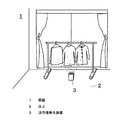
図1に示すように、部屋1の床上2には、活性種発生装置3が配置されている。
As shown in FIG. 1, an
この活性種発生装置3は、部屋内の空気中にラジカルなどの活性種を供給することで、この活性種による清浄化作用により、空気を清浄化するものである。また、活性種を含む空気を衣類やカーテン等にあてることによって、衣類やカーテンの脱臭・除菌などの効果が期待できる。
The
図2は、図1における活性種発生装置3の断面図を示している。図3は、図2とは部品配置が異なる活性種発生装置3の断面図を示している。
FIG. 2 shows a cross-sectional view of the
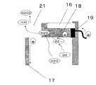
活性種発生装置3は、吸気口4と排気口5を有する本体ケース6と、この本体ケース6内には、送風手段7と、活性種発生手段8とを備えている。
The
本体ケース6は、略中央に位置する仕切板部9によって、吸気口4と排気口5とを連通する風路部10と、空間部11とに分けられている。
The
送風手段7は、本体ケース6の仕切板部9に固定された電動機12と、この電動機12によって回転する羽根部13と、この羽根部13を囲むケーシング部14とから形成している。ケーシング部14の吸込口15は、本体ケース6の吸気口4に対向している。送風手段7によって、吸気口4から吸い込んだ空気は、活性種発生手段8の一部を介して、排気口5へ送風されるものである。
The air blowing means 7 is formed of an
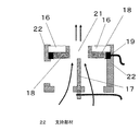
活性種発生手段8は、絶縁性基板16と、この絶縁性基板16に対向して配置された放電電極17と、絶縁性基板16に接する吸着手段18と、対向電極19と、電源20とから形成している。
The active species generating means 8 includes an
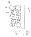
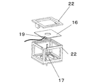
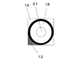
絶縁性基板16は、平板形状で略中央に開口である孔部21を有し、絶縁性基板16の端部が支持部材22を介して本体ケースの仕切板部9に固定されている。図2の部品配置では、送風手段7によって、吸気口4から吸い込んだ空気の一部は、放電電極17の周囲を通り、孔部21を介して、排気口5へ送風されるものである。図3の部品配置では、孔部21は、本体ケース6の排気口5に対向しており、送風手段7によって、吸気口4から吸い込んだ空気の一部は、放電電極17の周囲を通り、孔部21を介して、排気口5へ送風されるものである。絶縁性基板16は、セラミック基板であっても、フッ素などの樹脂基板であっても良い。セラミック基板として、シリカ、アルミ、マグネシウムのうちいずれか1つを含む基板であっても、アルミナ基板であっても良い。オゾンやラジカルで腐食されにくい無機系のものあるいはフッ素樹脂であれば良いためである。絶縁性基板16の表面抵抗は、1010Ω/□以上であることが望ましい。
The
放電電極17は、棒形状で、絶縁性基板16の一方面、および孔部21に対向し、絶縁性基板16の風上側に配置されている。図3の配置では、棒形状の放電電極17は、送風手段7によって送風される空気の送風方向と平行に延びている。そして、放電電極17の先端は、絶縁性基板16から数ミリメートル〜数十ミリメートル程度の所定距離を隔てて、孔部21の内方略中央に位置するものである。放電電極17の材質は、コロナ放電をさせるSUSなどのステンレスやタングステンなどである。
The
対向電極19は、SUSなどのステンレス、アルミ、金、銀、銅などで形成され、絶縁性基板16の周縁部に固定されている。なお、これらに限られること無く、導電性の素材であれば良い。対向電極19の表面抵抗は、10-1Ω/□以下であることが望ましい。
The
電源20は、本体ケース6の空間部11に位置し、放電電極17と、対向電極19とに、電圧を印加するものである。
The
吸着手段18は、絶縁性基板16の一方面側の表面、つまり、絶縁性基板16の風上側の面と、孔部21の内面とに設けられ、対向電極19と接している。吸着手段18の表面抵抗は、106から1010Ω/□であることが望ましい。
The suction means 18 is provided on the surface on one side of the
図4、図5、図6、図7および図8を用いて説明する。図4は、絶縁性基板16および吸着手段18部分の側断面図である。図5は、図3の部品配置における絶縁性基板16、吸着手段18、放電電極17、対向電極19、支持部材22を示す側断面図である。図6は、絶縁性基板16、放電電極17、支持部材22を示す斜視図である。図7は、絶縁性基板16、放電電極17、対向電極19、支持部材22の構成を示す展開図である。図8は、絶縁性基板16を放電電極17側から見たときの平面図である。
This will be described with reference to FIGS. 4, 5, 6, 7 and 8. FIG. 4 is a sectional side view of the
図4に示すように、吸着手段18は、絶縁性基板16の近傍の水分を吸着する吸着剤23と、この吸着剤23と絶縁性基板16を接着する接着剤24とから形成している。吸着剤23は、水を吸着する平均粒子径0.5マイクロメートルから数十マイクロメートル程度の粒子で、表面に細孔25を有しているゼオライトである。なお、吸着剤23としてゼオライトを例に挙げたが、吸着剤23は、ナノレベルの細孔25を有し、いわゆるKelvinの毛管凝縮現象により細孔内で水蒸気が凝縮し得るような細孔25を有する構造を有する多孔質構造体であれば、シリカ、ゼオライト、デシカイト、アロフィン、イモゴライトなどでも、これらのうちいずれか1つを含むものでも良い。また、粒子間の隙間を利用して水を吸着する、多孔質アルミナ、多孔質シリカ、多孔質チタニアであっても良い。なお、吸着剤23は、細孔25に空気中の水蒸気を吸着させるものであるが、細孔25が接着剤24の粒子で埋まりにくい平均粒子径であれば、空気中の水蒸気を吸着することができる。なお、吸着剤23は接着剤24よりも平均粒子径が大きいものであっても良い。
As shown in FIG. 4, the
接着剤24は、吸着剤23と、絶縁性基板16とを接着するコロイダルシリカである。なお、接着剤24は、ゼオライトなどの吸着剤23の平均粒子径より小さく、ゼオライトの表面に開いている細孔25よりも大きい平均粒子径であれば良い。また、細孔25を閉塞させなければ、接着剤24としてガラス粉や、シリケート化合物を用いてもよい。
The adhesive 24 is colloidal silica that adheres the adsorbent 23 and the insulating
ここで、図9のように、放電電極17にプラスの電圧を印加した場合について説明を行う。図9のように、この放電電極17に、電源20により放電電圧をプラス約3〜10kVで印加を行うと、放電電極17表面に強い電界が形成される。放電電極17にプラスの高電圧が印加されているため、空気中に存在する遊離電子が流れ込む。このとき、対向電極19は、マイナス状態となっているので、その結果、電子が移動することで、対向電極19から放電電極17へ電子が流れる。この状態がコロナ放電であって、このコロナ放電の力で後述のごとく、OHラジカル(活性種の一例)が発生する。
Here, a case where a positive voltage is applied to the
更に詳細に説明すると、セラミック製の絶縁性基板16と吸着剤23は、接着剤24により接着されている。吸着剤23の表面はナノレベルの細孔25を有し、空気中の水分は、この細孔25内で水蒸気が凝縮することにより、水分を吸着することが知られている(Kelvinの毛管凝縮現象)。これにより、ゼオライトなどの吸着手段18に、空気中の水分が吸着され、電子が流れやすくなる。放電電極17にプラスの高電圧を印加してプラスコロナ放電を行うと、吸着剤23中の電子は、放電電極17に強い力で引き寄せられるため、電子が高速で移動する。電子が、吸着剤23の近くに有る酸素分子と衝突すると、酸素分子に電子が一つ増えた状態の酸素分子の陰イオンが発生する。その後、酸素分子陰イオンが、絶縁性基板16の表面に吸着された水分子と反応をすることで、OHラジカルなどの活性種を発生する。吸着した水分の周辺でコロナ放電が起こることにより、水分が電子と反応しやすくなるため、OHラジカルの発生をより行いやすくするものである。
More specifically, the ceramic insulating
本実施形態における特徴は、絶縁性基板16の孔部21の内面と、絶縁性基板16の一方面表面とに吸着手段18を備え、放電電極17の先端が、孔部21の内方略中央に位置する点である。これにより、放電電極17と対向電極19間に高電圧が印加された場合に、放電電極17と対向電極19間を流れる電流は、放電電極17から絶縁性基板16に設けた放電電極17の周囲に位置する吸着手段18を流れた後に、対向電極19へと到達することになる。
A feature of the present embodiment is that the suction means 18 is provided on the inner surface of the
つまり、放電電極17を中心として円周方向の周囲に吸着手段18が位置するので、吸着手段18の広い範囲に電流が均一に分散することになり、広い範囲で均一に分散して放電するため、結果として活性種を安定して発生させることができるものである。また、円筒棒状の放電電極17の放電部分は、先端部の断面形状が円状になっているため 放電電極17を中心として円周方向に広い範囲に分散して放電が発生する。その結果、先端が鋭利な針状の放電電極を用いる場合に比べて、局所的な放電集中が起こりにくく、放電電極17の劣化を抑制することができ、結果として活性種を安定して発生させることができるものである。さらに、吸着手段18の広い範囲に電流が均一に分散するので、OHラジカルなどの活性種の発生量が増加するものである。
That is, since the suction means 18 is located around the
なお、本実施の形態において放電電極17は、プラスに印加したものであるが、この放電電極17に印加する電圧はプラスであっても、マイナスであっても良い。
In this embodiment, the
なお、本実施の形態では、絶縁性基板16の表面の一部に吸着手段18を有しているが、絶縁性基板16の表面の全部や、側面に吸着手段18を有していても良い。これにより、吸着手段18に吸着された水を効率的に分解することができる。
In the present embodiment, the suction means 18 is provided on a part of the surface of the insulating
また、放電電極17は単一の材料で形成したものである。これにより、めっき等の処理をした場合に比べ、放電電極17の耐久性の向上が図れるものである。
The
また、放電電極17の先端の断面形状と、絶縁性基板16の孔部21の形状は、同種の形状である。具体的には、放電電極17の断面形状と、絶縁性基板16の孔部21の形状は、円形状である。
The cross-sectional shape at the tip of the
すなわち、放電電極17の先端の周囲と、絶縁性基板16の孔部21との内面との距離が、均一になる。これにより、吸着手段18の広い範囲に電流が分散することになり、放電電極17の放電部分も、同様に放電電極17の広い範囲から分散して放電するため、放電電極17での劣化を抑制することができ、結果として活性種を安定して発生させることができるものである。
That is, the distance between the periphery of the tip of the
また、放電電極17の先端が、絶縁性基板16における一方面側寄りに位置する構成としたものである。これにより、絶縁性基板16の孔部との内面に設けた吸着手段18全体の広い範囲に電流が分散し易くなるので、OHラジカルの発生量が増加するものである。図5の例では、吸着手段18を備えた面に放電電極17の先端を配置している。
In addition, the tip of the
また、放電電極17の先端と対向電極19との距離は、放電電極17の先端と吸着手段18との距離より長いものである。具体的には、放電電極17と対向電極19間を流れる電流は、例えば放電電極17から絶縁性基板16の孔部21の内面を覆う吸着手段18を流れた後に、続いて絶縁性基板16の一方面表面の吸着手段18を流れ、その後ようやく対向電極19へと到達することになり、つまり沿面距離が長いので、その結果として火花放電が起こらず、安全性の向上が図れるものである。
The distance between the tip of the
また、対向電極19は、絶縁性基板16における一方面の裏側に位置する他方面、つまり、風下側面、又は絶縁性基板16における一方面と他方面との間の外周面に接して設けられているものであっても良い。これにより、放電電極17から流れる電子が、絶縁性基板16の表面を伝って流れる際に、電子の移動する距離である、いわゆる沿面距離が伸びることで、火花放電を起こりにくくなる。
The
なお、これに限られること無く、対向電極19を絶縁性基板16の表面に設ける場合には、十分な沿面距離を確保した状態で配置することが必要となる。
However, the present invention is not limited to this, and when the
次に、図10のように、放電電極17にマイナスの電圧を印加した場合について説明を行う。放電電極17に、電源により放電電圧をマイナス約3〜10KVで印加を行うと、放電電極17表面に強い電界が形成される。放電電極17にマイナスの高電圧が印加されているため、空気中に遊離電子が放出される。対向電極19に接した絶縁性基板16は、プラス側となる。その結果、電子が移動することで、対向電極19から放電電極17へ電流が流れる。
Next, a case where a negative voltage is applied to the
図10の放電電極17から空気に放出された電子は、対向電極19の強い電界に強い力で引き寄せられるため、電子が高速で移動し、空気中の分子などと衝突する。このとき高速で移動している電子が、空気中の酸素分子と衝突するすると、酸素分子に電子が一つ増えた状態の酸素分子の陰イオンが発生する。その後、酸素分子陰イオンが、絶縁性基板の表面に吸着された水分子と反応をすることで、OHラジカルが発生する。
The electrons released from the
上記のようなマイナスに印加された放電電極17からの放電であるいわゆるマイナスコロナ放電を行うことにより、吸着手段18周辺の水分が電子と反応することにより、OHラジカルの発生をより行いやすくするものである。
By performing the so-called negative corona discharge, which is a discharge from the
さらに、このように、放電電極17と対向電極19間に吸着手段18を介して面方向に電子が流れるため、沿面距離が長くなり、絶縁性基板16の表面を電流が伝って流れるものである。
Further, as described above, electrons flow in the surface direction between the
以上、図9、図10のようにして発生したOHラジカル(活性種)は、図2または図3の送風手段7からの送風により、活性種発生装置3の排気口5から室内へ排出される。このOHラジカルを含む空気を部屋1内に供給することで、空気中の菌を不活化することができる。また、空気中の臭いを分解して取り除くことで、脱臭効果を発揮させることができる。
As described above, the OH radicals (active species) generated as shown in FIGS. 9 and 10 are discharged into the room from the
以上のように本発明は、本体ケースと、前記本体ケース内に設けられた平板形状の絶縁性基板と、前記絶縁性基板の一方面に対向して配置された棒形状の放電電極と、前記絶縁性基板に接する対向電極と、前記放電電極と前記対向電極とに電圧を印加する電源とを設け、前記絶縁性基板は孔部を有し、この孔部の内面と前記絶縁性基板の一方面表面とに水分を吸着する吸着手段を備え、前記放電電極の先端は、前記孔部の内方略中央に位置する構成としたものであるので、活性種が安定して発生するようにすることができる。 As described above, the present invention includes a main body case, a flat plate-shaped insulating substrate provided in the main body case, a rod-shaped discharge electrode disposed to face one surface of the insulating substrate, A counter electrode in contact with the insulating substrate and a power source for applying a voltage to the discharge electrode and the counter electrode are provided. The insulating substrate has a hole, and an inner surface of the hole and one of the insulating substrates An adsorption means for adsorbing moisture is provided on the surface of the surface, and the tip of the discharge electrode is positioned approximately in the center of the hole, so that active species are stably generated. Can do.
すなわち、本発明においては、絶縁性基板の孔部の内面と、絶縁性基板の一方面表面とに吸着手段を備え、放電電極の先端が、孔部の内方略中央に位置することにより、放電電極と対向電極間に高電圧が印加された場合に、放電電極と対向電極間を流れる電流は、放電電極から絶縁性基板に設けた放電電極の周囲に位置する吸着手段を流れた後に、対向電極へと到達することになる。 That is, in the present invention, the inner surface of the hole portion of the insulating substrate and the one surface surface of the insulating substrate are provided with adsorption means, and the tip of the discharge electrode is positioned approximately in the center of the hole portion. When a high voltage is applied between the electrode and the counter electrode, the current flowing between the discharge electrode and the counter electrode flows through the adsorption means located around the discharge electrode provided on the insulating substrate from the discharge electrode, Will reach the electrode.
つまり、放電電極の周囲に吸着手段が位置するので、吸着手段の広い範囲に電流が分散することになり、放電電極の放電部分も、同様に放電電極の広い範囲から分散して放電するため、放電電極での劣化を抑制することができ、結果として活性種が安定して発生するようにすることができるものである。 In other words, since the suction means is located around the discharge electrode, the current is dispersed over a wide range of the suction means, and the discharge portion of the discharge electrode is similarly dispersed and discharged from the wide range of the discharge electrode. Deterioration at the discharge electrode can be suppressed, and as a result, active species can be stably generated.
したがって、空気清浄機としての活用が期待される。 Therefore, utilization as an air cleaner is expected.
1 部屋
2 床上
3 活性種発生装置
4 吸気口
5 排気口
6 本体ケース
7 送風手段
8 活性種発生手段
9 仕切板部
10 風路部
11 空間部
12 電動機
13 羽根部
14 ケーシング部
15 吸込口
16 絶縁性基板
17 放電電極
18 吸着手段
19 対向電極
20 電源
21 孔部
22 支持部材
23 吸着剤
24 接着剤
25 細孔
DESCRIPTION OF
Claims (6)
前記本体ケース内に設けられた平板形状の絶縁性基板と、
前記絶縁性基板の一方面に対向して配置された棒形状の放電電極と、
前記絶縁性基板に接する対向電極と、
前記放電電極と前記対向電極とに電圧を印加する電源とを設け、
前記絶縁性基板は孔部を有し、
この孔部の内面と前記絶縁性基板の一方面表面とに水分を吸着する吸着手段を備え、
前記放電電極の先端は、
前記孔部の内方略中央に位置する構成とした活性種発生装置。 A body case,
A flat plate-shaped insulating substrate provided in the main body case;
A rod-shaped discharge electrode disposed to face one surface of the insulating substrate;
A counter electrode in contact with the insulating substrate;
A power source for applying a voltage to the discharge electrode and the counter electrode;
The insulating substrate has a hole;
Adsorbing means for adsorbing moisture on the inner surface of the hole and one surface of the insulating substrate;
The tip of the discharge electrode is
An active species generator configured to be positioned substantially in the center of the hole.
前記絶縁性基板の前記孔部の形状は、
同種の形状である請求項1または2に記載の活性種発生装置。 A cross-sectional shape of the tip of the discharge electrode;
The shape of the hole of the insulating substrate is
The active species generator according to claim 1 or 2, which has the same shape.
前記絶縁性基板の前記孔部の形状は、
円形状である請求項3に記載の活性種発生装置。 A cross-sectional shape of the discharge electrode;
The shape of the hole of the insulating substrate is
The active species generator according to claim 3, which has a circular shape.
前記絶縁性基板における一方面表面寄りに位置する構成としたことを特徴とする請求項1〜4のいずれか1つに記載の活性種発生装置。 The tip of the discharge electrode is
The active species generator according to any one of claims 1 to 4, wherein the active species generator is configured to be positioned closer to one surface of the insulating substrate.
前記放電電極の先端と前記吸着手段との距離より長いことを特徴とする請求項5に記載の活性種発生装置。 The distance between the tip of the discharge electrode and the counter electrode is
6. The active species generator according to claim 5, wherein the active species generator is longer than the distance between the tip of the discharge electrode and the adsorption means.
Priority Applications (3)
| Application Number | Priority Date | Filing Date | Title |
|---|---|---|---|
| JP2011084290A JP5810259B2 (en) | 2011-04-06 | 2011-04-06 | Active species generator |
| PCT/JP2012/000952 WO2012114674A1 (en) | 2011-02-22 | 2012-02-14 | Active species generating unit and active species generating device |
| CN201280010048.XA CN103402553B (en) | 2011-02-22 | 2012-02-14 | Active species generating unit and active species generating device |
Applications Claiming Priority (1)
| Application Number | Priority Date | Filing Date | Title |
|---|---|---|---|
| JP2011084290A JP5810259B2 (en) | 2011-04-06 | 2011-04-06 | Active species generator |
Publications (2)
| Publication Number | Publication Date |
|---|---|
| JP2012217536A true JP2012217536A (en) | 2012-11-12 |
| JP5810259B2 JP5810259B2 (en) | 2015-11-11 |
Family
ID=47269740
Family Applications (1)
| Application Number | Title | Priority Date | Filing Date |
|---|---|---|---|
| JP2011084290A Active JP5810259B2 (en) | 2011-02-22 | 2011-04-06 | Active species generator |
Country Status (1)
| Country | Link |
|---|---|
| JP (1) | JP5810259B2 (en) |
Cited By (1)
| Publication number | Priority date | Publication date | Assignee | Title |
|---|---|---|---|---|
| KR20170030654A (en) | 2012-12-27 | 2017-03-17 | 우시오덴키 가부시키가이샤 | Desmearing method and desmearing device |
Citations (3)
| Publication number | Priority date | Publication date | Assignee | Title |
|---|---|---|---|---|
| JPH08227789A (en) * | 1995-02-22 | 1996-09-03 | Midori Anzen Co Ltd | Resin electrode |
| JP2005192822A (en) * | 2004-01-08 | 2005-07-21 | Matsushita Electric Ind Co Ltd | Purification method and purification device |
| JP2006320613A (en) * | 2005-05-20 | 2006-11-30 | Mitsubishi Electric Corp | Air purifier |
-
2011
- 2011-04-06 JP JP2011084290A patent/JP5810259B2/en active Active
Patent Citations (3)
| Publication number | Priority date | Publication date | Assignee | Title |
|---|---|---|---|---|
| JPH08227789A (en) * | 1995-02-22 | 1996-09-03 | Midori Anzen Co Ltd | Resin electrode |
| JP2005192822A (en) * | 2004-01-08 | 2005-07-21 | Matsushita Electric Ind Co Ltd | Purification method and purification device |
| JP2006320613A (en) * | 2005-05-20 | 2006-11-30 | Mitsubishi Electric Corp | Air purifier |
Cited By (2)
| Publication number | Priority date | Publication date | Assignee | Title |
|---|---|---|---|---|
| KR20170030654A (en) | 2012-12-27 | 2017-03-17 | 우시오덴키 가부시키가이샤 | Desmearing method and desmearing device |
| US11102889B2 (en) | 2012-12-27 | 2021-08-24 | Ushio Denki Kabushiki Kaisha | Desmearing method and desmearing device |
Also Published As
| Publication number | Publication date |
|---|---|
| JP5810259B2 (en) | 2015-11-11 |
Similar Documents
| Publication | Publication Date | Title |
|---|---|---|
| JP6581661B2 (en) | Plasma source containing porous dielectric | |
| CN102428034B (en) | Discharge unit for liquid treatment, humidity control device, and warm water supplier | |
| CN108097042A (en) | A kind of ion field arrangement for catalytic purification and method | |
| CN104415659A (en) | Plasma-driven catalyst system for disinfection and purification of gases | |
| KR20060071406A (en) | Gas treatment equipment | |
| JP2008289801A (en) | Gas purification device | |
| JP2015070921A (en) | Deodorization device | |
| CN103429276B (en) | Spike generation unit and use its spike generator | |
| JP2006280698A (en) | Air purification device | |
| JP6002934B2 (en) | Discharge unit and air purifier using the same | |
| JP5810259B2 (en) | Active species generator | |
| WO2012114674A1 (en) | Active species generating unit and active species generating device | |
| JP5873960B2 (en) | Active species generator | |
| JP5810260B2 (en) | Active species generator | |
| JP6641182B2 (en) | Ion wind type liquid vaporizer and air conditioner | |
| JP2014044888A (en) | Discharge unit and air cleaning apparatus using the same | |
| JP2015047173A (en) | Deodorization sterilizer | |
| JP2014121424A (en) | Discharge unit and air cleaner using the same | |
| WO2004023615A1 (en) | Ion generating device, method for manufacturing ion generating device, ion generator having ion generating device, and electric apparatus having ion generator | |
| JP2013000531A (en) | Active species generation device | |
| WO2014002453A1 (en) | Electricity discharging unit and air cleaning device using same | |
| JP2013034516A (en) | Active species generating apparatus | |
| JP5974269B2 (en) | Active species generating unit and active species generating apparatus using the same | |
| JP2007144278A (en) | Deodorizing device and air conditioner equipped with the same | |
| CN219092374U (en) | LTP honeycomb plasma dust collection module |
Legal Events
| Date | Code | Title | Description |
|---|---|---|---|
| A621 | Written request for application examination |
Free format text: JAPANESE INTERMEDIATE CODE: A621 Effective date: 20140325 |
|
| RD01 | Notification of change of attorney |
Free format text: JAPANESE INTERMEDIATE CODE: A7421 Effective date: 20140414 |
|
| A711 | Notification of change in applicant |
Free format text: JAPANESE INTERMEDIATE CODE: A711 Effective date: 20141007 |
|
| A131 | Notification of reasons for refusal |
Free format text: JAPANESE INTERMEDIATE CODE: A131 Effective date: 20150113 |
|
| A521 | Written amendment |
Free format text: JAPANESE INTERMEDIATE CODE: A523 Effective date: 20150216 |
|
| TRDD | Decision of grant or rejection written | ||
| A01 | Written decision to grant a patent or to grant a registration (utility model) |
Free format text: JAPANESE INTERMEDIATE CODE: A01 Effective date: 20150310 |
|
| A61 | First payment of annual fees (during grant procedure) |
Free format text: JAPANESE INTERMEDIATE CODE: A61 Effective date: 20150323 |
|
| R151 | Written notification of patent or utility model registration |
Ref document number: 5810259 Country of ref document: JP Free format text: JAPANESE INTERMEDIATE CODE: R151 |