JP5810260B2 - Active species generator - Google Patents
Active species generator Download PDFInfo
- Publication number
- JP5810260B2 JP5810260B2 JP2011084291A JP2011084291A JP5810260B2 JP 5810260 B2 JP5810260 B2 JP 5810260B2 JP 2011084291 A JP2011084291 A JP 2011084291A JP 2011084291 A JP2011084291 A JP 2011084291A JP 5810260 B2 JP5810260 B2 JP 5810260B2
- Authority
- JP
- Japan
- Prior art keywords
- insulating substrate
- active species
- discharge electrode
- opening
- species generator
- Prior art date
- Legal status (The legal status is an assumption and is not a legal conclusion. Google has not performed a legal analysis and makes no representation as to the accuracy of the status listed.)
- Active
Links
Images


Description
本発明は、室内空間の除菌や脱臭などを行う活性種発生装置に関するものである。 The present invention relates to an active species generator that performs sterilization and deodorization of an indoor space.
近年、空気中にラジカルなどの活性種を供給し、この活性種による清浄化作用により、この空気を清浄化する活性種発生装置が開発されている。 In recent years, active species generators have been developed that supply active species such as radicals into the air and purify the air by the cleaning action of the active species.
従来のこの種、活性種発生装置は、本体ケースと、放電電極と、この放電電極に対向する対向電極と、これらの放電電極と対向電極とに電圧を印加する電源と、対向電極の表面に設けた吸着手段とを備えた構成であった(例えば特許文献1参照)。 This kind of active species generating device has a main body case, a discharge electrode, a counter electrode opposite to the discharge electrode, a power source for applying a voltage to the discharge electrode and the counter electrode, and a surface of the counter electrode. It was the structure provided with the provided adsorption | suction means (for example, refer patent document 1).
上記従来の活性種発生装置は、放電電極と対向電極間に電圧を印加することで、コロナ放電を行わせ、これによって吸着手段に吸着した水分を分解し、活性種を発生させるようになっていた。 The conventional active species generator is configured to generate corona discharge by applying a voltage between the discharge electrode and the counter electrode, thereby decomposing moisture adsorbed on the adsorption means and generating active species. It was.
このような構成において、コロナ放電によって放電電極と対向電極間に流れる電流は、放電電極から導電体である対向電極への最短経路となる吸着手段の厚み方向に流れ易いので、放電電極の近傍の狭い範囲に集中して電子が流れやすい傾向があった。狭い範囲に電流が集中することによって、集中的に生成した高濃度の活性種が、吸着手段の劣化を起こす可能性があった。また、集中的に生成した活性種が吸着手段を剥離させて放電電極と対向電極間で火花放電を発生させる可能性があり、安全性を高めることが求められている。 In such a configuration, the current flowing between the discharge electrode and the counter electrode due to corona discharge tends to flow in the thickness direction of the adsorption means that is the shortest path from the discharge electrode to the counter electrode as a conductor. There was a tendency for electrons to flow easily in a narrow area. When the current is concentrated in a narrow range, there is a possibility that the concentrated active species having a high concentration may cause the adsorption means to deteriorate. In addition, active species generated in a concentrated manner may cause the adsorbing means to peel off and generate a spark discharge between the discharge electrode and the counter electrode, which is required to improve safety.
そこで、本発明は、放電電極と対向電極の絶縁性を高め、安全性を高めるとともに、より広い範囲で活性種を生成させることにより、活性種の発生量を増加して、活性種による浄化作用を向上させることを目的とするものである。 Therefore, the present invention improves the insulation between the discharge electrode and the counter electrode, enhances safety, and generates active species in a wider range, thereby increasing the generation amount of active species and purifying action by active species. The purpose is to improve.
そして、この目的を達成するために本発明は、本体ケースと、前記本体ケース内に設けられた絶縁性基板と、前記絶縁性基板の表面から所定間隔を存して配置された放電電極と、前記絶縁性基板に接する対向電極と、前記放電電極と前記対向電極とに電圧を印加する電源と、前記絶縁性基板を覆うように塗布された、近傍の水分を吸着する吸着手段と、を備え、前記絶縁性基板は、開口部を有し、この開口部の前記放電電極側の開口縁は、外方に拡開する拡開傾斜面とするとともに前記吸着手段により覆われ、前記放電電極の先端は、前記拡開傾斜面を有する開口部に対して垂直方向に対向配置する構成とし、これにより所期の目的を達成するものである。 And in order to achieve this object, the present invention includes a main body case, an insulating substrate provided in the main body case, a discharge electrode disposed at a predetermined interval from the surface of the insulating substrate, A counter electrode that is in contact with the insulating substrate; a power source that applies a voltage to the discharge electrode and the counter electrode; and an adsorbing means that adsorbs moisture in the vicinity applied so as to cover the insulating substrate. The insulating substrate has an opening, and an opening edge of the opening on the discharge electrode side is an expanded inclined surface that expands outward and is covered by the adsorption means, The tip is configured so as to be opposed to the opening having the expanding inclined surface in the vertical direction, thereby achieving the intended purpose.
以上のように本発明は、本体ケースと、前記本体ケース内に設けられた絶縁性基板と、前記絶縁性基板の表面から所定間隔を存して配置された放電電極と、前記絶縁性基板に接する対向電極と、前記放電電極と前記対向電極とに電圧を印加する電源と、前記絶縁性基板を覆うように塗布された、近傍の水分を吸着する吸着手段と、を備え、前記絶縁性基板は、開口部を有し、この開口部の前記放電電極側の開口縁は、外方に拡開する拡開傾斜面とするとともに前記吸着手段により覆われ、前記放電電極の先端は、前記拡開傾斜面を有する開口部に対して垂直方向に対向配置する構成としたものであるので、放電電極と対向電極の絶縁性を高め、安全性を高めるとともに、より広い範囲で活性種を生成させることにより、活性種の発生量を増加して、活性種による浄化作用を向上させることができる。 As described above, the present invention provides a main body case, an insulating substrate provided in the main body case, a discharge electrode disposed at a predetermined interval from the surface of the insulating substrate, and the insulating substrate. A counter electrode in contact therewith, a power source for applying a voltage to the discharge electrode and the counter electrode, and an adsorbing means for adsorbing moisture in the vicinity applied so as to cover the insulating substrate. Has an opening, and an opening edge of the opening on the discharge electrode side is an expanding inclined surface expanding outward and is covered by the suction means, and a tip of the discharge electrode is covered with the expanding electrode. Since it is configured so as to be opposed to the opening having an open inclined surface in the vertical direction, the insulation between the discharge electrode and the counter electrode is improved, safety is increased, and active species are generated in a wider range. Increase the amount of active species generated Te, it is possible to improve the cleaning action of the active species.
すなわち、本発明においては、本体ケースと、前記本体ケース内に設けられた絶縁性基板と、前記絶縁性基板の表面から所定間隔を存して配置された放電電極と、前記絶縁性基板に接する対向電極と、前記放電電極と前記対向電極とに電圧を印加する電源と、前記絶縁性基板を覆うように塗布された、近傍の水分を吸着する吸着手段と、を備えたことにより、放電電極と対向電極間に高電圧が印加された場合でも、放電電極と対向電極間を流れる電流は、放電電極から絶縁性基板の外周に位置する吸着手段を面方向に流れた後に、対向電極へと到達することになる。 That is, in the present invention, a main body case, an insulating substrate provided in the main body case, a discharge electrode disposed at a predetermined interval from the surface of the insulating substrate, and the insulating substrate are in contact with each other. A discharge electrode comprising: a counter electrode; a power source for applying a voltage to the discharge electrode and the counter electrode; and an adsorption means for adsorbing moisture in the vicinity applied to cover the insulating substrate. Even when a high voltage is applied between the discharge electrode and the counter electrode, the current flowing between the discharge electrode and the counter electrode flows from the discharge electrode to the counter electrode after flowing in the surface direction through the suction means located on the outer periphery of the insulating substrate. Will reach.
つまり、放電電極と対向電極間に高電圧が印加された場合でも、放電電極と対向電極間の沿面距離が長くなり、電子が吸着手段を介してより長い距離にわたって流れることになるため、瞬間的な短絡による火花放電が起こりにくく、その結果として、安全性の向上が図れるものである。また、放電電極と対向電極間の沿面距離が長くなることにより、放電範囲が広がり、より広い範囲から活性種が生成するため、安全性の向上が図れるものである。 That is, even when a high voltage is applied between the discharge electrode and the counter electrode, the creepage distance between the discharge electrode and the counter electrode is increased, and electrons flow over a longer distance through the adsorption means. Spark discharge due to a short circuit is unlikely to occur, and as a result, safety can be improved. In addition, since the creeping distance between the discharge electrode and the counter electrode is increased, the discharge range is widened, and active species are generated from a wider range, so that safety can be improved.
また、さらに、本発明においては、前記絶縁性基板は、開口部を有し、この開口部の前記放電電極側の開口縁は、外方に拡開する拡開傾斜面とするとともに前記吸着手段により覆われ、前記放電電極の先端は、前記拡開傾斜面を有する開口部に対して垂直方向に対向配置することにより、開口部の開口縁が傾斜しない場合と比較して、開口部の開口縁の拡開傾斜面の傾斜が、放電電極に対向する吸着手段の表面積と吸着手段の存在量を増加させるので、放電電極から放出された電子がより多く吸着手段の表面に到達することになる。 Furthermore, in the present invention, the insulating substrate has an opening, and an opening edge of the opening on the discharge electrode side is an expanding inclined surface expanding outward and the suction means. The tip of the discharge electrode is disposed perpendicularly to the opening having the widened inclined surface, so that the opening edge of the opening is less than the case where the opening edge of the opening is not inclined. The inclination of the edge expansion slope increases the surface area of the adsorption means facing the discharge electrode and the abundance of the adsorption means, so that more electrons emitted from the discharge electrode reach the surface of the adsorption means. .
その結果、吸着手段に吸着した水分がより多くコロナ放電により分解され、活性種の発生量を増加することにより、活性種による浄化作用の向上が図れるものである。 As a result, more of the water adsorbed on the adsorbing means is decomposed by corona discharge and the amount of active species generated is increased, so that the purification action by the active species can be improved.
(実施の形態1)
以下、本発明の実施の形態について、図面を参照しながら説明する。
(Embodiment 1)
Hereinafter, embodiments of the present invention will be described with reference to the drawings.
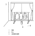
図1に示すように、部屋1の床2上には、活性種発生装置3が配置されている。
As shown in FIG. 1, an
この活性種発生装置3は、部屋1内の空気中にラジカルなどの活性種を供給することで、この活性種による清浄化作用により、空気を清浄化するものである。
The
図2は、図1における活性種発生装置3の断面図を示している。図3は、図2とは部品配置が異なる活性種発生装置3の断面図を示している。この活性種発生装置3を起動させると、プラスチック製の本体ケース4側面に設けられた吸込口5から、部屋1内の空気が本体ケース4内に流入する。本体ケース4内に流入した空気は、送風機6により本体ケース4内の上部まで移動する。
FIG. 2 shows a cross-sectional view of the
本体ケース4内の上方には、セラミック又は、フッ素などの樹脂製の板状の絶縁性基板7が設けられている。この絶縁性基板7は、空気の流れに対して、図2では平行、図3では垂直方向に支持部材18によって本体ケース4に固定されている。
A plate-like
絶縁性基板7は、セラミック基板であっても、フッ素などの樹脂基板であっても良い。セラミック基板として、シリカ、アルミ、マグネシウムのうちいずれか1つを含む基板であっても、アルミナ基板であっても良い。オゾンやラジカルで腐食されにくい無機系のものあるいはフッ素樹脂であれば良いためである。
The
絶縁性基板7の表面抵抗は、1010Ω/□以上であることが望ましい。
The surface resistance of the
更に、この絶縁性基板7と対向する位置に数ミリメートル〜数十ミリメートル程度の所定距離を隔てて、コロナ放電をさせるSUSやタングステンなどを用いた放電電極12が配置され、さらに、絶縁性基板7には対向電極13が設けられている。
Further, a
放電電極12は、棒状またはワイヤ状であり、その先端の形状は、先端に向かって径が小さくなった針形状、または、放電電極12の長手方向に対して略垂直な断面としたものでもよい。
The
放電電極の先端と反対の端部が、電源14に接続されている。
The end opposite to the tip of the discharge electrode is connected to the
対向電極13は、SUSなどのステンレス、アルミ、金、銀、銅などで形成されている。なお、対向電極13の素材は、これらに限られること無く、導電性の素材であれば良い。
The
対向電極13の表面抵抗は、10-1Ω/□以下であることが望ましい。
The surface resistance of the
放電電極12は、電源14により印加されると、放電電極12の先端から放電する。電流は、放電電極12から、絶縁性基板7の表面22を覆う吸着手段8の表面を経由して、対向電極13に流れる。
The
図4、図5、図6、図7および図8を用いて説明する。 This will be described with reference to FIGS. 4, 5, 6, 7 and 8.
図4は、絶縁性基板7および吸着手段8部分の側面図である。
FIG. 4 is a side view of the
図5は、図3の部品配置における絶縁性基板7、吸着手段8、放電電極12、対向電極13、支持部材18を示す側断面図である。
FIG. 5 is a side sectional view showing the
図6は、図2の部品配置における絶縁性基板7、対向電極13、支持部材18を示す斜視図である。
6 is a perspective view showing the
図7は、図2の部品配置における絶縁性基板7、対向電極13、支持部材18の構成を示す展開図である。
FIG. 7 is a developed view showing the configuration of the
図8は、絶縁性基板7を対向電極13側から見たときの平面図である。
FIG. 8 is a plan view of the
図5から図8に示すように、絶縁性基板7は、放電電極12と対向する表面22と、裏面23と、表面22と裏面23の外周においてこれらの表面22と裏面23に接続された側面24を有している。絶縁性基板7は四角形であり、表面22から裏面23に貫通する開口部20を有している。なお、図6、図7では、吸着手段8は、他の構成を分かりやすくするため、図示していない。
As shown in FIGS. 5 to 8, the
なお、絶縁性基板7の形状は、本実施の形態では、四角形であるが、後述する吸着手段8を設けるための面積を有していれば、円形・長方形・六角形等の他の形状でもよい。
In this embodiment, the shape of the insulating
なお、図8に示すように、絶縁性基板7の開口部20は、円形状としてもよい。これにより、放電電極12に高電圧をかけることにより放電電極12の先端から発生するイオン風が、円形状の開口部20を効率よく通過して、送風機6により送風される空気中に放出されるので、絶縁性基板7を覆う吸着手段8の表面に生じた活性種が吸着手段8の表面から移動し、拡散しやすくなるという効果を奏する。
As shown in FIG. 8, the
図5に示すように、開口部20の放電電極12側の開口縁は、外方に拡開する拡開傾斜面21となっている。
As shown in FIG. 5, the opening edge of the
すなわち、表面22の開口部20の径は、裏面23の開口部20の径より大きくなるように、拡開傾斜面21が傾斜している。
That is, the expanding
絶縁性基板7の開口部20の周囲および開口部20の拡開傾斜面21は、吸着手段8により覆われている。この吸着手段8は、図4に示すように、水を吸着する平均粒子径0.5マイクロメートルから数十マイクロメートル程度の粒子で構成されたゼオライトなどの吸着剤9を有している。更に、吸着手段8は、吸着剤9と、絶縁性基板7を接着するコロイダルシリカなどの接着剤10を有している。
The periphery of the
この吸着手段8を構成する吸着剤9は、表面に細孔11を有しているため、接着剤10は、ゼオライトなどの吸着剤9の平均粒子径より小さく、ゼオライトの表面に開いている細孔11よりも大きい平均粒子径であれば良い。また、細孔11を閉塞させなければ、接着剤10としてガラス粉や、シリケート化合物を用いてもよい。
Since the adsorbent 9 constituting the adsorbing means 8 has
本実施の形態における吸着剤9は、細孔11に空気中の水蒸気を吸着させるものであるが、細孔11が接着剤10の粒子で埋まりにくい平均粒子径であれば、空気中の水蒸気を吸着することができる。なお、吸着剤9は接着剤10よりも平均粒子径が大きいものであっても良い。
The adsorbent 9 in the present embodiment adsorbs water vapor in the air to the
また、本実施の形態では、吸着剤9としてゼオライトを例に挙げたが、吸着剤9は、ナノレベルの細孔11を有し、いわゆるKelvinの毛管凝縮現象により細孔内で水蒸気が凝縮し得るような細孔を有する構造を有する多孔質構造体であれば、シリカ、ゼオライト、デシカイト、アロフィン、イモゴライトなどでも、これらのうちいずれか1つを含むものでも良い。また、粒子間の隙間を利用して水を吸着する、多孔質アルミナ、多孔質シリカ、多孔質チタニアであっても良い。
In the present embodiment, zeolite is used as an example of the adsorbent 9, but the adsorbent 9 has nano-
対向電極13は、絶縁性基板7と吸着手段8に接するように配置される。
The
これにより、放電電極12と対向電極13間を流れる電流は、例えば放電電極12から絶縁性基板7の表面22を覆う吸着手段8を流れた後に、対向電極13へと到達することになり、つまり沿面距離が長いので、その結果として火花放電が起こらず、安全性の向上が図れるものである。
Thereby, for example, the current flowing between the
なお、絶縁性基板7の表面22を覆う吸着手段8は、半導電性であり、吸着手段8の表面抵抗は、106から1010Ω/□であることが望ましい。放電電極12と対向電極13間との間に高電圧が印加されたとき、電流は一方の電極から放電されて絶縁性基板7の表面22を覆う吸着手段8を伝って他方の電極へと流れる。この際に、本体ケース4内に設けられた絶縁性基板7と、絶縁性基板7から所定距離を隔てて配置された放電電極12と、絶縁性基板7の表面22を覆う吸着手段8に接する対向電極13と、絶縁性基板7の表面22を覆うとともに、絶縁性基板7の近傍の水分を吸着する吸着手段8を設けることにより、電子が移動する距離であるいわゆる沿面距離が伸びることとなる。これにより火花放電の発生を低減させることができ、安全性が向上するのである。
The suction means 8 covering the
なお、絶縁性基板7の表面22を覆う吸着手段8の膜厚は、均一であることが望ましい。
The film thickness of the suction means 8 that covers the
表面22抵抗を均一にするためである。
This is to make the
吸着手段8は、絶縁性基板7の表面22にスクリーン印刷によりスキージで半導電インクを塗布したものである。半導電インクは、ゼオライトなどの吸着剤およびコロイダルシリカなどの接着剤10を含み、前記成分を溶剤に混合あるいは溶解させたものである。絶縁性基板7の開口部20上をスクリーンを介してスキージが通過することにより、開口部20の拡開傾斜面21に、半導電インクが、押し出され、押し出された半導電インクは、開口部20の拡開傾斜面21の斜面の中程25にいくほど膜厚が厚くなるような曲面を形成して拡開傾斜面21を覆う。従って、吸着手段8は、絶縁性基板7の開口部20の拡開傾斜面21の中程にいくほど膜厚が厚くなるような曲面を形成する。
The suction means 8 is obtained by applying semiconductive ink to the
このように、開口部20の拡開傾斜面21は、吸着手段8により覆われている。
Thus, the expansion inclined
これにより、開口部20の開口縁が傾斜しない場合と比較して、放電電極12の先端に対向する開口縁の面積、つまり、拡開傾斜面21の面積が増加する。その結果、放電電極12の先端に対向する拡開傾斜面21を覆う吸着手段8の表面積も増加する。また、拡開傾斜面21上に接着される吸着手段の存在量が増加する。
Thereby, compared with the case where the opening edge of the
これにより、放電電極12の先端から放出された電子がより多く吸着手段8の表面に到達することになる。これにより、吸着手段8に吸着した水分がより多くコロナ放電により分解され、活性種の発生量を増加することにより、活性種による浄化作用の向上を図ることができるのである。
Thereby, more electrons emitted from the tip of the
放電電極12は、その先端を絶縁性基板7の表面22の開口部20に向けるように対向して配置され、放電電極12の先端と絶縁性基板7の表面22との間に数ミリメートル〜数十ミリメートル程度の所定距離を隔て、開口部20内側に位置するように突設されている。
The
また、放電電極12は、絶縁性基板7の開口部20の中心垂直軸上に位置するという構成にしてもよい。すなわち、放電電極12は、その長手方向の中心軸が、開口部20の投影面の略中心垂直軸上に位置するように配置するという構成にしてもよい。これにより、放電電極12に高電圧をかけることにより放電電極12の先端から発生するイオン風が、絶縁性基板7の開口部20の略中心方向に向けて流れるため、イオン風は、絶縁性基板7に遮られることなく、開口部20を通過して、送風機6により送風される空気中に放出されるので、絶縁性基板7を覆う吸着手段8の表面に生じた活性種が吸着手段8の表面から移動し、拡散しやすくなるという効果を奏する。
The
対向電極13は、吸着手段8と接していれば、絶縁性基板7の裏面23又は側面24に接して設けられているものであっても良い(図示なし)。これにより、放電電極12から流れる電子が、絶縁性基板7の表面22を覆う吸着手段8の表面を伝って流れる際に、電子の移動する距離である、いわゆる沿面距離が伸びることで、火花放電を起こりにくくなる。
The
なお、これに限られること無く、対向電極13を絶縁性基板7の表面22に設ける場合には、十分な沿面距離を確保した状態で配置することが必要となる。
However, the present invention is not limited to this, and when the
また、図5に示すように、対向電極13の表面には絶縁性被覆26を設けてもよい。絶縁性被覆26により、放電電極12から対向電極13へ直接到達して火花放電を起こすことが防止でき、さらに安全性の向上が図れるものである。これによって、十分な沿面距離を確保できない場合でも、安全性を確保することができる。絶縁性被覆としては、フッ素樹脂・塩ビ樹脂などの絶縁性テープを接着する方法、ガラスペースト・セラミック系接着剤を塗布して乾燥焼成する方法などを用いることができる。
Further, as shown in FIG. 5, an insulating
放電電極12に高電圧をかけることで、絶縁性基板7の表面22を覆う吸着手段8の表面にてラジカルやオゾンや過酸化水素などの活性種が発生する。放電電極12の先端から絶縁性基板7に向けてイオン風が発生し、このイオン風は、絶縁性基板7の開口部20を通って、送風機により送風される空気中に放出されるので、絶縁性基板7を覆う吸着手段8の表面に生じた活性種が吸着手段8の表面から移動し、拡散しやすくなる。
By applying a high voltage to the
すなわち、この放電電極12に、電源14により放電電圧をプラス約3〜10KVで印加を行うと、放電電極12の表面に強い電界が形成される。放電電極12にプラスの高電圧が印加されているため、空気中に存在する遊離電子が流れ込む。このとき、対向電極13は、マイナス状態となっているので、その結果、電子が移動することで、対向電極13から放電電極12へ電子が流れる。この状態がコロナ放電であって、このコロナ放電の力で後述のごとく、OHラジカル(活性種の一例)が発生する。
That is, when a discharge voltage is applied to the
次に、図9のように、放電電極12にプラスの電圧を印加した場合について説明を行う。
Next, a case where a positive voltage is applied to the
セラミック製の絶縁性基板7と吸着剤9は、接着剤10により接着されている。吸着剤9の表面22はナノレベルの細孔を有し、空気中の水分は、この細孔内で水蒸気が凝縮することにより、水分を吸着することが知られている(Kelvinの毛管凝縮現象)。これにより、ゼオライトなどの吸着手段8に、空気中の水分が吸着され、電子が流れやすくなる。放電電極12にプラスの高電圧を印加してプラスコロナ放電を行うと、吸着剤9中の電子は、放電電極12に強い力で引き寄せられるため、電子が高速で移動する。電子が、吸着剤9の近くに有る酸素分子と衝突すると、酸素分子に電子が一つ増えた状態の酸素分子の陰イオンが発生する。その後、酸素分子陰イオンが、絶縁性基板7の表面22に吸着された水分子と反応をすることで、OHラジカルなどの活性種を発生する。吸着した水分の周辺でコロナ放電が起こることにより、水分が電子と反応しやすくなるため、OHラジカルの発生をより行いやすくするものである。
The ceramic insulating
なお、本実施の形態において放電電極12は、プラスに印加したものであるが、この放電電極12に印加する電圧はプラスであっても、マイナスであっても良い。
In this embodiment, the
図10のように、放電電極12にマイナスの電圧を印加した場合について説明を行う。放電電極12に、電源14により放電電圧をマイナス約3〜10KVで印加を行うと、放電電極12の表面に強い電界が形成される。放電電極12にマイナスの高電圧が印加されているため、空気中に遊離電子が放出される。対向電極13に接した絶縁性基板7は、プラス側となる。その結果、電子が移動することで、対向電極13から放電電極12へ電流が流れる。
A case where a negative voltage is applied to the
放電電極12から空気に放出された電子は、対向電極13の強い電界に強い力で引き寄せられるため、電子が高速で移動し、空気中の分子などと衝突する。このとき高速で移動している電子が、空気中の酸素分子と衝突するすると、酸素分子に電子が一つ増えた状態の酸素分子の陰イオンが発生する。その後、酸素分子陰イオンが、絶縁性基板7の表面22に吸着された水分子と反応をすることで、OHラジカルが発生する。
The electrons emitted from the
上記のようなマイナスに印加された放電電極12からの放電であるいわゆるマイナスコロナ放電を行うことにより、吸着手段8周辺の水分が電子と反応することにより、OHラジカルの発生をより行いやすくするものである。
By performing so-called negative corona discharge, which is discharge from the
さらに、このように、放電電極12と対向電極13間に吸着手段8を介して面方向に電子が流れるため、沿面距離が長くなり、絶縁性基板7の表面22を電流が伝って流れるものである。
Further, as described above, electrons flow in the surface direction between the
以上、図9、図10のようにして発生したOHラジカル(活性種)は、図2または図3の送風機6からの送風により、活性種発生装置3の排気口15から室内へ排出される。このOHラジカルを含む空気を部屋1内に供給することで、空気中の菌を不活化することができる。また、空気中の臭いを分解して取り除くことで、脱臭効果を発揮させることができる。
As described above, the OH radicals (active species) generated as shown in FIGS. 9 and 10 are discharged into the room from the
以上のように本発明は、本体ケースと、前記本体ケース内に設けられた絶縁性基板と、前記絶縁性基板の表面から所定間隔を存して配置された放電電極と、前記絶縁性基板に接する対向電極と、前記放電電極と前記対向電極とに電圧を印加する電源と、前記絶縁性基板を覆うように塗布された、近傍の水分を吸着する吸着手段と、を備え、前記絶縁性基板は、開口部を有し、この開口部の前記放電電極側の開口縁は、外方に拡開する拡開傾斜面とするとともに前記吸着手段により覆われ、前記放電電極の先端は、前記拡開傾斜面を有する開口部に対して垂直方向に対向配置する構成としたものであるので、放電電極と対向電極の絶縁性を高め、安全性を高めるとともに、より広い範囲で活性種を生成させることにより、活性種の発生量を増加して、活性種による浄化作用を向上させることができる。 As described above, the present invention provides a main body case, an insulating substrate provided in the main body case, a discharge electrode disposed at a predetermined interval from the surface of the insulating substrate, and the insulating substrate. A counter electrode in contact therewith, a power source for applying a voltage to the discharge electrode and the counter electrode, and an adsorbing means for adsorbing moisture in the vicinity applied so as to cover the insulating substrate. Has an opening, and an opening edge of the opening on the discharge electrode side is an expanding inclined surface expanding outward and is covered by the suction means, and a tip of the discharge electrode is covered with the expanding electrode. Since it is configured so as to be opposed to the opening having an open inclined surface in the vertical direction, the insulation between the discharge electrode and the counter electrode is improved, safety is increased, and active species are generated in a wider range. Increase the amount of active species generated Te, it is possible to improve the cleaning action of the active species.
本体ケースと、前記本体ケース内に設けられた絶縁性基板と、前記絶縁性基板の表面から所定間隔を存して配置された放電電極と、前記絶縁性基板に接する対向電極と、前記放電電極と前記対向電極とに電圧を印加する電源と、前記絶縁性基板を覆うように塗布された、近傍の水分を吸着する吸着手段と、を備えたことにより、放電電極と対向電極間に高電圧が印加された場合でも、放電電極と対向電極間を流れる電流は、放電電極から絶縁性基板の外周に位置する吸着手段を面方向に流れた後に、対向電極へと到達することになる。 A main body case, an insulating substrate provided in the main body case, a discharge electrode disposed at a predetermined interval from a surface of the insulating substrate, a counter electrode in contact with the insulating substrate, and the discharge electrode And a power source for applying a voltage to the counter electrode, and an adsorbing means for adsorbing moisture in the vicinity applied so as to cover the insulating substrate, so that a high voltage is applied between the discharge electrode and the counter electrode. Even when is applied, the current flowing between the discharge electrode and the counter electrode reaches the counter electrode after flowing in the surface direction from the discharge electrode through the suction means located on the outer periphery of the insulating substrate.
つまり、放電電極と対向電極間に高電圧が印加された場合でも、放電電極と対向電極間の沿面距離が長くなり、電子が吸着手段を介してより長い距離にわたって流れることになるため、瞬間的な短絡による火花放電が起こりにくく、その結果として、安全性の向上が図れるものである。また、放電電極と対向電極間の沿面距離が長くなることにより、放電範囲が広がり、より広い範囲から活性種が生成するため、安全性の向上が図れるものである。 That is, even when a high voltage is applied between the discharge electrode and the counter electrode, the creepage distance between the discharge electrode and the counter electrode is increased, and electrons flow over a longer distance through the adsorption means. Spark discharge due to a short circuit is unlikely to occur, and as a result, safety can be improved. In addition, since the creeping distance between the discharge electrode and the counter electrode is increased, the discharge range is widened, and active species are generated from a wider range, so that safety can be improved.
また、さらに、本発明においては、前記絶縁性基板は、開口部を有し、この開口部の前記放電電極側の開口縁は、外方に拡開する拡開傾斜面とするとともに前記吸着手段により覆われ、前記放電電極の先端は、前記拡開傾斜面を有する開口部に対して垂直方向に対向配置することにより、開口部の開口縁が傾斜しない場合と比較して、開口部の開口縁の拡開傾斜面の傾斜が、放電電極に対向する吸着手段の表面積と吸着手段の存在量を増加させるので、放電電極から放出された電子がより多く吸着手段の表面に到達することになる。 Furthermore, in the present invention, the insulating substrate has an opening, and an opening edge of the opening on the discharge electrode side is an expanding inclined surface expanding outward and the suction means. The tip of the discharge electrode is disposed perpendicularly to the opening having the widened inclined surface, so that the opening edge of the opening is less than the case where the opening edge of the opening is not inclined. The inclination of the edge expansion slope increases the surface area of the adsorption means facing the discharge electrode and the abundance of the adsorption means, so that more electrons emitted from the discharge electrode reach the surface of the adsorption means. .
その結果、吸着手段に吸着した水分がより多くコロナ放電により分解され、活性種の発生量を増加することにより、活性種による浄化作用の向上が図れるものである。 As a result, more of the water adsorbed on the adsorbing means is decomposed by corona discharge and the amount of active species generated is increased, so that the purification action by the active species can be improved.
したがって、空気清浄機としての活用が期待される。 Therefore, utilization as an air cleaner is expected.
1 部屋
2 床
3 活性種発生装置
4 本体ケース
5 吸込口
6 送風機
7 絶縁性基板
8 吸着手段
9 吸着剤
10 接着剤
11 細孔
12 放電電極
13 対向電極
14 電源
15 排気口
18 支持部材
20 開口部
21 拡開傾斜面
22 表面
23 裏面
24 側面
25 斜面の中程
26 絶縁性被覆
1
Claims (13)
前記本体ケース内に設けられた絶縁性基板と、
前記絶縁性基板の表面から所定間隔を存して配置された放電電極と、
前記絶縁性基板に接する対向電極と、
前記放電電極と前記対向電極とに電圧を印加する電源と、
前記絶縁性基板を覆うように塗布された、近傍の水分を吸着する吸着手段とを備え、
前記絶縁性基板は、開口部を有し、
この開口部の前記放電電極側の開口縁は、外方に拡開する拡開傾斜面とするとともに前記吸着手段により覆われ、
前記放電電極の先端は、前記拡開傾斜面を有する開口部に対して垂直方向に対向配置することを特徴とする活性種発生装置。 A body case,
An insulating substrate provided in the main body case;
A discharge electrode disposed at a predetermined interval from the surface of the insulating substrate;
A counter electrode in contact with the insulating substrate;
A power source for applying a voltage to the discharge electrode and the counter electrode;
Adsorbing means for adsorbing moisture in the vicinity applied to cover the insulating substrate;
The insulating substrate has an opening;
The opening edge of the opening on the discharge electrode side is covered with the adsorbing means, with an expanding inclined surface expanding outward,
The active species generator is characterized in that the tip of the discharge electrode is disposed to face the opening having the expanding inclined surface in the vertical direction.
The discharge electrode, the active species generating apparatus according to claim 1, characterized in that located on the heart vertical axis within the opening of the insulating substrate.
Priority Applications (3)
| Application Number | Priority Date | Filing Date | Title |
|---|---|---|---|
| JP2011084291A JP5810260B2 (en) | 2011-04-06 | 2011-04-06 | Active species generator |
| PCT/JP2012/000952 WO2012114674A1 (en) | 2011-02-22 | 2012-02-14 | Active species generating unit and active species generating device |
| CN201280010048.XA CN103402553B (en) | 2011-02-22 | 2012-02-14 | Active species generating unit and active species generating device |
Applications Claiming Priority (1)
| Application Number | Priority Date | Filing Date | Title |
|---|---|---|---|
| JP2011084291A JP5810260B2 (en) | 2011-04-06 | 2011-04-06 | Active species generator |
Publications (2)
| Publication Number | Publication Date |
|---|---|
| JP2012217537A JP2012217537A (en) | 2012-11-12 |
| JP5810260B2 true JP5810260B2 (en) | 2015-11-11 |
Family
ID=47269741
Family Applications (1)
| Application Number | Title | Priority Date | Filing Date |
|---|---|---|---|
| JP2011084291A Active JP5810260B2 (en) | 2011-02-22 | 2011-04-06 | Active species generator |
Country Status (1)
| Country | Link |
|---|---|
| JP (1) | JP5810260B2 (en) |
Families Citing this family (1)
| Publication number | Priority date | Publication date | Assignee | Title |
|---|---|---|---|---|
| US11026173B2 (en) | 2016-12-14 | 2021-06-01 | Telefonaktiebolaget Lm Ericsson (Publ) | Wake-up radio |
Family Cites Families (3)
| Publication number | Priority date | Publication date | Assignee | Title |
|---|---|---|---|---|
| JP4149526B2 (en) * | 1995-02-22 | 2008-09-10 | ミドリ安全株式会社 | Resin electrode |
| JP2005192822A (en) * | 2004-01-08 | 2005-07-21 | Matsushita Electric Ind Co Ltd | Purifying method and purifying apparatus |
| JP2006320613A (en) * | 2005-05-20 | 2006-11-30 | Mitsubishi Electric Corp | Air cleaning apparatus |
-
2011
- 2011-04-06 JP JP2011084291A patent/JP5810260B2/en active Active
Also Published As
| Publication number | Publication date |
|---|---|
| JP2012217537A (en) | 2012-11-12 |
Similar Documents
| Publication | Publication Date | Title |
|---|---|---|
| JP6581661B2 (en) | Plasma source containing porous dielectric | |
| JP3852429B2 (en) | Air cleaner | |
| JP2003017297A (en) | Discharge device and plasma reactor | |
| WO2013010328A1 (en) | Air purifier with electric field regeneration | |
| JP2006280698A (en) | Air cleaner | |
| US20150224516A1 (en) | Air purification device | |
| CN107073391B (en) | Humidity control device | |
| JP6043944B2 (en) | Active species generating unit and active species generating apparatus using the same | |
| JP5810260B2 (en) | Active species generator | |
| WO2012114674A1 (en) | Active species generating unit and active species generating device | |
| KR20090084429A (en) | Air conditioner with anion and cation producer for a vehicle | |
| JP5873960B2 (en) | Active species generator | |
| JP2007144278A (en) | Deodorizer, and air conditioner equipped with the same | |
| TWI601919B (en) | Plasma purification module | |
| JP5810259B2 (en) | Active species generator | |
| JP4706198B2 (en) | Air purification device | |
| JPH11319489A (en) | Catalyst structural body and deodorizing device having catalyst structural body | |
| JP7196550B2 (en) | air purifier | |
| JP4673169B2 (en) | Deodorization device | |
| KR0138712B1 (en) | Deodorizing filter | |
| JP2013000531A (en) | Active species generation device | |
| JP2010110692A (en) | Charging apparatus and air treatment apparatus | |
| JP2014044888A (en) | Discharge unit and air cleaning apparatus using the same | |
| JP5974269B2 (en) | Active species generating unit and active species generating apparatus using the same | |
| JP2013034516A (en) | Active species generating apparatus |
Legal Events
| Date | Code | Title | Description |
|---|---|---|---|
| A621 | Written request for application examination |
Free format text: JAPANESE INTERMEDIATE CODE: A621 Effective date: 20140325 |
|
| RD01 | Notification of change of attorney |
Free format text: JAPANESE INTERMEDIATE CODE: A7421 Effective date: 20140414 |
|
| A711 | Notification of change in applicant |
Free format text: JAPANESE INTERMEDIATE CODE: A711 Effective date: 20141007 |
|
| A131 | Notification of reasons for refusal |
Free format text: JAPANESE INTERMEDIATE CODE: A131 Effective date: 20150113 |
|
| A521 | Written amendment |
Free format text: JAPANESE INTERMEDIATE CODE: A523 Effective date: 20150216 |
|
| TRDD | Decision of grant or rejection written | ||
| A01 | Written decision to grant a patent or to grant a registration (utility model) |
Free format text: JAPANESE INTERMEDIATE CODE: A01 Effective date: 20150310 |
|
| A61 | First payment of annual fees (during grant procedure) |
Free format text: JAPANESE INTERMEDIATE CODE: A61 Effective date: 20150323 |
|
| R151 | Written notification of patent or utility model registration |
Ref document number: 5810260 Country of ref document: JP Free format text: JAPANESE INTERMEDIATE CODE: R151 |