JP2008289801A - Gas purification device - Google Patents
Gas purification device Download PDFInfo
- Publication number
- JP2008289801A JP2008289801A JP2007140942A JP2007140942A JP2008289801A JP 2008289801 A JP2008289801 A JP 2008289801A JP 2007140942 A JP2007140942 A JP 2007140942A JP 2007140942 A JP2007140942 A JP 2007140942A JP 2008289801 A JP2008289801 A JP 2008289801A
- Authority
- JP
- Japan
- Prior art keywords
- discharge
- electrode
- purification
- gas
- electrodes
- Prior art date
- Legal status (The legal status is an assumption and is not a legal conclusion. Google has not performed a legal analysis and makes no representation as to the accuracy of the status listed.)
- Pending
Links
- 238000000746 purification Methods 0.000 title claims abstract description 116
- CBENFWSGALASAD-UHFFFAOYSA-N Ozone Chemical compound [O-][O+]=O CBENFWSGALASAD-UHFFFAOYSA-N 0.000 claims abstract description 45
- 239000012535 impurity Substances 0.000 claims abstract description 32
- 239000003054 catalyst Substances 0.000 claims abstract description 27
- 230000006698 induction Effects 0.000 claims abstract description 16
- 230000004888 barrier function Effects 0.000 claims abstract description 9
- 238000000354 decomposition reaction Methods 0.000 claims description 32
- 239000011941 photocatalyst Substances 0.000 claims description 19
- 239000003463 adsorbent Substances 0.000 claims description 13
- 230000001939 inductive effect Effects 0.000 claims description 11
- 239000011810 insulating material Substances 0.000 claims description 9
- 230000003647 oxidation Effects 0.000 claims description 6
- 238000007254 oxidation reaction Methods 0.000 claims description 6
- 238000005949 ozonolysis reaction Methods 0.000 abstract 2
- 239000007789 gas Substances 0.000 description 63
- 239000000126 substance Substances 0.000 description 13
- 230000009471 action Effects 0.000 description 9
- 230000000694 effects Effects 0.000 description 7
- 230000004048 modification Effects 0.000 description 7
- 238000012986 modification Methods 0.000 description 7
- 238000007664 blowing Methods 0.000 description 6
- 229910052751 metal Inorganic materials 0.000 description 6
- 239000002184 metal Substances 0.000 description 6
- 239000000428 dust Substances 0.000 description 5
- OKTJSMMVPCPJKN-UHFFFAOYSA-N Carbon Chemical compound [C] OKTJSMMVPCPJKN-UHFFFAOYSA-N 0.000 description 4
- 230000008901 benefit Effects 0.000 description 4
- 239000011888 foil Substances 0.000 description 4
- 238000010891 electric arc Methods 0.000 description 3
- 150000003254 radicals Chemical class 0.000 description 3
- 238000003860 storage Methods 0.000 description 3
- 238000011144 upstream manufacturing Methods 0.000 description 3
- 239000000919 ceramic Substances 0.000 description 2
- 230000001877 deodorizing effect Effects 0.000 description 2
- 238000007599 discharging Methods 0.000 description 2
- 239000011521 glass Substances 0.000 description 2
- 239000000543 intermediate Substances 0.000 description 2
- 238000000034 method Methods 0.000 description 2
- 230000008569 process Effects 0.000 description 2
- 230000007704 transition Effects 0.000 description 2
- XLYOFNOQVPJJNP-UHFFFAOYSA-N water Substances O XLYOFNOQVPJJNP-UHFFFAOYSA-N 0.000 description 2
- 239000004593 Epoxy Substances 0.000 description 1
- 239000004642 Polyimide Substances 0.000 description 1
- 239000004809 Teflon Substances 0.000 description 1
- 229920006362 Teflon® Polymers 0.000 description 1
- GWEVSGVZZGPLCZ-UHFFFAOYSA-N Titan oxide Chemical compound O=[Ti]=O GWEVSGVZZGPLCZ-UHFFFAOYSA-N 0.000 description 1
- 230000003213 activating effect Effects 0.000 description 1
- 230000004913 activation Effects 0.000 description 1
- PNEYBMLMFCGWSK-UHFFFAOYSA-N aluminium oxide Inorganic materials [O-2].[O-2].[O-2].[Al+3].[Al+3] PNEYBMLMFCGWSK-UHFFFAOYSA-N 0.000 description 1
- 239000002280 amphoteric surfactant Substances 0.000 description 1
- QVGXLLKOCUKJST-UHFFFAOYSA-N atomic oxygen Chemical compound [O] QVGXLLKOCUKJST-UHFFFAOYSA-N 0.000 description 1
- 238000005452 bending Methods 0.000 description 1
- 230000015556 catabolic process Effects 0.000 description 1
- 239000002781 deodorant agent Substances 0.000 description 1
- 238000010586 diagram Methods 0.000 description 1
- 235000013305 food Nutrition 0.000 description 1
- 229940094952 green tea extract Drugs 0.000 description 1
- 235000020688 green tea extract Nutrition 0.000 description 1
- 238000010438 heat treatment Methods 0.000 description 1
- 239000012212 insulator Substances 0.000 description 1
- 230000014759 maintenance of location Effects 0.000 description 1
- 239000000463 material Substances 0.000 description 1
- 239000010445 mica Substances 0.000 description 1
- 229910052618 mica group Inorganic materials 0.000 description 1
- 238000006864 oxidative decomposition reaction Methods 0.000 description 1
- 229910052760 oxygen Inorganic materials 0.000 description 1
- 239000001301 oxygen Substances 0.000 description 1
- 229920003223 poly(pyromellitimide-1,4-diphenyl ether) Polymers 0.000 description 1
- 229920001721 polyimide Polymers 0.000 description 1
- 229920005989 resin Polymers 0.000 description 1
- 239000011347 resin Substances 0.000 description 1
- 239000005060 rubber Substances 0.000 description 1
- 229920002050 silicone resin Polymers 0.000 description 1
- 230000001954 sterilising effect Effects 0.000 description 1
- 230000002195 synergetic effect Effects 0.000 description 1
- OGIDPMRJRNCKJF-UHFFFAOYSA-N titanium oxide Inorganic materials [Ti]=O OGIDPMRJRNCKJF-UHFFFAOYSA-N 0.000 description 1
Images


Abstract
Description
本発明は、高周波電圧が印加された電極間に発生する誘電体バリア放電により、浄化対象となるガスを一定方向に送流させて浄化処理部に導き、この浄化処理部内においてガス中の不純物を分解・吸着するガス浄化装置に関する。 According to the present invention, a dielectric barrier discharge generated between electrodes to which a high-frequency voltage is applied causes a gas to be purified to flow in a certain direction and lead it to a purification treatment unit. The present invention relates to a gas purification device that decomposes and adsorbs.
住空間、倉庫、冷蔵庫などの食品保管庫、その他の保管庫内における有害物質の除去、悪臭防止、殺菌等(以下、不純物または不純物の浄化と総称する)を目的として、高性能で省エネルギー型の脱臭装置や空気清浄機などのガス浄化装置が求められている。 A high-performance, energy-saving type for the purpose of removing harmful substances, preventing malodors, sterilizing, etc. (hereinafter collectively referred to as impurities or impurity purification) in food storage such as living spaces, warehouses and refrigerators, and other storages Gas purification devices such as deodorizing devices and air purifiers are demanded.
このようなガス浄化装置は、一定空間の空気やその他のガス(以下、空気や排ガスなど浄化対象のガスを総称して、ガスという)を取り込んで浄化し、再び元の空間に戻すことを繰返し、空間内を浄化するものである。このため、従来、ガスを循環させるための送風装置を持つものが一般的だった。 Such a gas purification device repeatedly takes in and purifies air and other gases (hereinafter collectively referred to as gases to be purified such as air and exhaust gas) and returns them to the original space. It purifies the space. For this reason, it has been common to have a blower for circulating gas.
このような従来のガス浄化装置の一例を、図12を用いて説明する。図中、200は脱臭装置、201は浄化対象のガスを取り込むためのファン送風機、202はガス中の不純物を吸着及び/または分解する浄化処理部、203はファン送風機の駆動電源、211は浄化対象のガス吸入口、212は浄化処理されたガスの放出口を示す。
An example of such a conventional gas purification apparatus will be described with reference to FIG. In the figure, 200 is a deodorizing device, 201 is a fan blower for taking in gas to be purified, 202 is a purification processing unit that adsorbs and / or decomposes impurities in the gas, 203 is a drive power supply for the fan blower, and 211 is a purification target.
浄化処理部202は、活性炭などの不純物の吸着材を備えたり、臭い成分などの不純物を分解するための微小コロナ放電発生部と発生したオゾンを処理するオゾン触媒とで構成されたりする。なお、ガス処理に放電が使われる場合は、電源204が付属する。また、これらの吸着材と放電発生部とが併用されることもある。
The
このような浄化装置は、保管庫内或いは室内のガスを装置内部に取り込む必要から、必ずファンを装備しなければならない。しかし、ファンの装備は、振動、騒音の発生や装置駆動に電力が必要といった問題点を有していると共に、浄化装置の小型化にも障害となっていた。 Such a purification apparatus must be equipped with a fan because it is necessary to take gas in the storage or the room into the apparatus. However, the fan equipment has problems such as generation of vibration, noise, and the necessity of electric power for driving the apparatus, and it has been an obstacle to downsizing the purification apparatus.
このようなファンを備えた浄化装置の問題点を解決するために、電極間に生じる放電によって発生する気流を、浄化対象ガスの送風手段として使用する提案も従来から知られている。すなわち、電極間に高圧の直流電圧を印加すると、電極周辺の空間に絶縁破壊が生じ、コロナ放電が発生し、電極の先端から多量の電子が放出され、空間内の塵埃や気体分子に付着し、イオン化する。イオン化した塵埃や気体分子は、誘引電極に向かって流れ、誘引電極に捕集されるので、このような気体分子の流れを空気清浄機の送風手段として使用する。(特許文献1、特許文献2参照)
確かに、イオン風を利用した前記特許文献に記載の従来技術においては、送風用のファンが不要となる利点はあるものの、気流の発生手段として直流電圧を印加した電極間に生じる放電を利用していたため、電極間に水滴やほこりが付着して、アーク放電に遷移してしまう可能性があった。特に、家庭や工場などのガス中に塵埃が存在する使用環境では、電極へのほこり、ごみや水滴付着によって、アーク放電に遷移し、電極にダメージを与える可能性があり、このアーク放電防止策を講じることで、製品価格が割高になる欠点があった。 Certainly, in the prior art described in the above-mentioned patent document using the ionic wind, there is an advantage that a fan for blowing air is unnecessary, but the discharge generated between the electrodes to which a DC voltage is applied is used as a means for generating an air flow. Therefore, there was a possibility that water droplets or dust would adhere between the electrodes and transition to arc discharge. In particular, in environments where dust is present in gases such as homes and factories, there is a possibility of transition to arc discharge due to dust, dirt or water droplets adhering to the electrode, which may damage the electrode. There was a drawback that the product price was expensive by taking.
また、放電を利用した浄化装置においては、高電圧が印加された電極間に発生するオゾンによる不純物の分解作用が効果的に行われることが望ましいが、従来の電極間に直流電圧を印加する装置においては、オゾンの発生が十分とは言えず、不純物の分解作用が効果的に行えない欠点があった。 In addition, in a purifying device using discharge, it is desirable that the action of decomposing impurities by ozone generated between electrodes to which a high voltage is applied is effective, but a device that applies a DC voltage between conventional electrodes. However, the ozone generation is not sufficient, and there is a drawback that the impurity cannot be decomposed effectively.
本発明は、前記のような従来技術の問題点を解決するために提案されたもので、その目的は、高周波電圧を電極間に印加した際に発生する気流を利用することで、ファンレスタイプの小型単純化されたガス浄化装置を得ることにある。 The present invention has been proposed in order to solve the problems of the prior art as described above, and its purpose is to use a fanless type by utilizing an air flow generated when a high frequency voltage is applied between the electrodes. It is to obtain a small and simplified gas purification apparatus.
本発明の他の目的は、高周波電圧を印加された電極間においては、直流電圧印加時に比較してより多量のオゾンガスが発生すること、及びこのオゾン発生ガスを分解するためのオゾン分解触媒が、オゾンの分解時にガス中の不純物をも効果的に分解することに着目することにより、浄化性能に優れたガス浄化装置を提供することにある。 Another object of the present invention is that a larger amount of ozone gas is generated between electrodes to which a high-frequency voltage is applied than when a DC voltage is applied, and an ozone decomposition catalyst for decomposing this ozone-generating gas, It is an object of the present invention to provide a gas purification apparatus having excellent purification performance by paying attention to effectively decomposing impurities in the gas when decomposing ozone.
前記の目的を達成するために、本発明のガス浄化装置は、第1の放電電極と、これに誘電体を介して対向して設けられた第2の放電電極と、これら第1及び第2の放電電極に対して高周波電圧を印加する放電用電源とを備え、前記第1の電極、誘電体及び第2の電極を、前記第1の電極と第2の電極に対して高周波電圧を印加した場合にこれらの電極間に発生する誘電体バリア放電により一定方向に気流が流れるように配置してなる放電気流誘起部と、この放電気流誘起部における気流の流れ方向の後段に設置された浄化処理部と、この浄化処理部に供給されたガス中の不純物を浄化する浄化処理手段を備えていることを特徴とする。 In order to achieve the above object, a gas purification apparatus of the present invention includes a first discharge electrode, a second discharge electrode provided opposite to the first discharge electrode, and the first and second discharge electrodes. A discharge power source for applying a high-frequency voltage to the discharge electrodes of the first electrode, applying the high-frequency voltage to the first electrode, the dielectric and the second electrode, and applying the high-frequency voltage to the first electrode and the second electrode In this case, a discharge airflow inducing section is arranged so that the airflow flows in a certain direction due to a dielectric barrier discharge generated between these electrodes, and a purification installed downstream of the direction of airflow in the discharge airflow inducing section. The present invention is characterized by comprising a processing section and a purification processing means for purifying impurities in the gas supplied to the purification processing section.
また、前記放電気流誘起部が第1と第2の電極間に発生する誘電体バリア放電によりオゾンを生成するものであって、前記浄化処理手段がオゾン分解触媒を備えたものであり、このオゾン分解触媒におけるオゾンの分解作用に伴ってガス中の不純物をも同時に分解するものであることも、本発明の一態様である。 Further, the discharge air flow inducing section generates ozone by dielectric barrier discharge generated between the first and second electrodes, and the purification treatment means includes an ozone decomposition catalyst. It is also an aspect of the present invention that the impurities in the gas are decomposed simultaneously with the ozone decomposing action in the decomposition catalyst.
本発明によれば、誘電体を挟んで配置された電極間に高周波電圧を印加した場合に、一定方向に気流が発生する現象を利用することにより、ファンを使用することなく、処理対象のガスを浄化処理手段に送風することが可能になる。また、高周波電圧による放電を利用することでオゾンの発生を促すと同時に、オゾン分解触媒によるオゾン分解作用により、不純物の分解を効果的に実施できる。 According to the present invention, a gas to be processed can be used without using a fan by utilizing a phenomenon that an air flow is generated in a certain direction when a high frequency voltage is applied between electrodes arranged with a dielectric interposed therebetween. Can be sent to the purification processing means. In addition, by using discharge by high-frequency voltage, the generation of ozone is promoted, and at the same time, the decomposition of impurities can be effectively performed by the ozone decomposition action by the ozone decomposition catalyst.
(1)第1実施形態
(1−1)第1実施形態の構成
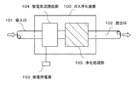
図1は本発明の第1実施形態のガス浄化装置の構成図である。図1中、100はガス浄化装置本体を示すものであって、このガス浄化装置100は、その内部がガス流通空間となったチャンバー状をしており、その入口側には浄化対象となるガスの吸入口101が、出口側には浄化されたガスの放出口102が設けられている。このガス浄化装置100内には、放電用電源103に接続された放電気流誘起部104と、その後段に設けられた浄化処理部105が組み込まれている。
(1) 1st Embodiment (1-1) Structure of 1st Embodiment FIG. 1: is a block diagram of the gas purification apparatus of 1st Embodiment of this invention. In FIG. 1, reference numeral 100 denotes a gas purification device main body. The gas purification device 100 has a chamber shape in which the inside is a gas circulation space, and a gas to be purified at the inlet side. The suction port 101 is provided with a purified gas discharge port 102 on the outlet side. In the gas purification apparatus 100, a discharge air
前記放電用電源103としては、商用周波数の放電用電源を使用することが可能であるが、それに限定されるものではなく、その出力電圧としては、パルス状(正極性、不極性、正負の両極性(交番電圧))や交流状(正弦波、断続正弦波)の波形を有するものが使用できる。また、高周波電源の周波数を別途設けた制御装置によって、フィードバック制御することも可能である。 The discharge power source 103 may be a commercial frequency discharge power source, but is not limited thereto, and the output voltage may be pulsed (both positive, nonpolar, positive and negative) (Alternating voltage)) and alternating current (sine wave, intermittent sine wave) waveforms can be used. Also, feedback control can be performed by a control device that separately provides the frequency of the high-frequency power source.
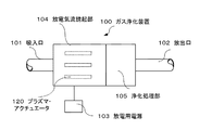
図1では、チャンバー状のケーシングを備えたガス浄化装置100内に、箱状の放電発生部104と浄化処理部105とをダクト106で結ぶように配置したが、図2に示すように、箱状の放電発生部104と同じく箱状の浄化処理部105とを直接一体化するような構成を採用することも可能である。
In FIG. 1, the box-shaped
前記放電気流誘起部104としては、一例として、図1や図2に示すように、複数枚のプラズマ・アクチュエータ120を処理対象ガスの送風方向と平行に一定の間隔を保って配置したものが使用される。
As the discharge air
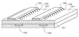
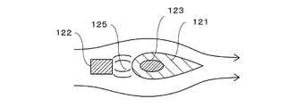
図3は、このプラズマ・アクチュエータ120の一例を示すものである。すなわち、ガスの送風方向と平行に配置された誘電体から構成された絶縁板121の一方の面(図中上面)に、気流方向とは直角に伸びる複数本の短冊状をした金属箔から成る第1の電極122が設けられ、絶縁板121の他の面(図中下面)には前記第1の電極122の全部をカバーするような大面積の幅が広い金属箔から成る第2の電極123が設けられている。
FIG. 3 shows an example of the
これら第1及び第2の電極122,123には、前記放電用電源103が接続され、高周波電圧の印加時に両電極間に放電が発生するように構成されている。この場合、前記細長い短冊状の第1の電極121における気流の上流側の縁は絶縁材124で覆われ、第1の電極122の片側だけが放電するように構成されている。
The first and
なお、前記絶縁板121や絶縁材124としては、ポリイミド、ガラスエポキシ、ゴム、テフロン(登録商標)、カプトン(登録商標)などの絶縁性樹脂や、アルミナ、ガラス、マイカなどの無機絶縁物などが使用される。
The
一方、前記浄化処理部105には、例えば活性炭、両性界面活性剤系消臭剤、緑茶抽出物、多孔質シリコーン樹脂などの不純物の吸着材や、粒状酸化チタンなどの光触媒やオゾン発生装置などの不純物分解装置を使用することができる。特に、本実施形態においては、前記第1と第2の電極間の放電により発生したオゾンが浄化装置外部に漏出することを防止するためのオゾン分解触媒を、不純物の浄化処理手段として使用する。
On the other hand, the
(1−2)第1実施形態の作用
次に、このような構成を有する第1実施形態の作用について説明する。
まず、放電気流誘起部104内に装備されたプラズマ・アクチュエータ120によって、処理対象となるガスが浄化処理部105に向かって送風される作用を説明する。
(1-2) Operation of the First Embodiment Next, the operation of the first embodiment having such a configuration will be described.
First, an operation in which a gas to be processed is blown toward the
第1と第2の電極122,123間に放電用電源103から高電圧を印加しこれが一定の閾値以上の電位差となると、両電極間には放電が発生し、放電に伴って放電プラズマが生成される。ここで、電極122,123間には誘電体である絶縁板121が介在しているので、高温下や不純物の存在下であってもアーク放電には至らず、安定に維持することが可能な誘電体バリア放電125が生じる。
When a high voltage is applied from the discharge power source 103 between the first and
また、誘電体バリア放電125は、絶縁板121の表面に沿って形成される沿面放電となり、この誘電体バリア放電125によって、所定の方向(第1の電極122から第2の電極123への方向)に気流を発生させることができる。この場合、第1と第2の電極122,123及び絶縁板121との位置関係を非対称形とすることが、一方の電極から他方の電極に向かう気流を発生させるための条件となる。
Further, the
すなわち、第1と第2の電極122,123が非対称形で配置された場合に、電極間に交番電圧が印加されると、第1の電極122に正電圧が印加された場合と負電圧が印加された場合とでは、向きは逆で早さの異なる気流が誘起されるので、この両方向の気流を時間平均すると一定方向の気流が得られる。特に、図3のように、第1の電極122の電極面積を第2の電極の電極面積に比較して小さくした場合には、小さな電極面積の第1の電極122から広い電極面積の第2の電極123に向かって気流が発生する。
That is, when the first and
このようにして、各プラズマ・アクチュエータ120によって発生した気流により、吸入口101から導入された処理対象となるガスが浄化処理部105に向かって送られる。浄化処理部105に達した浄化対象ガスは、浄化処理部105内の浄化処理手段により、ガス中の不純物を分解・吸着され、清浄化されたガスは放出口102から装置外部に排出される。
In this way, the gas to be processed introduced from the suction port 101 is sent toward the
この場合、本実施形態では、前記の放電気流誘起部104における両電極間に発生するプラズマ放電に伴い、オゾンを発生させている。特に、両電極間に印加する電圧が高周波電圧であるため、直流電圧を電極間に印加する従来技術に比較してオゾンの発生が効果的に行われる。この発生したオゾンは、その自然分解時にガス中の不純物を分解する作用を果たすため、高周波電圧の印加のみによっても従来技術よりも優れた分解作用が期待できる。
In this case, in the present embodiment, ozone is generated along with the plasma discharge generated between both electrodes in the discharge
しかも、本実施形態においては、浄化処理部105にオゾン分解触媒を配置することで、両電極間に発生したオゾンを触媒表面において積極的に分解することにより、その際、ガス中の不純物も同時に分解する。これにより、浄化装置外部にオゾンが排出される不都合を解消すると同時に、オゾンの分解を促進して、オゾン分解に伴う不純物の分解作用も向上させることができる。
Moreover, in the present embodiment, by disposing the ozone decomposition catalyst in the
すなわち、オゾン分解触媒表面では、オゾンが分解され途中の過程でOラディカル酸素が精製される。このラディカル種が触媒表面に吸着された有害物質や悪臭成分の酸化分解を促進し、装置の処理能力向上がなされる。 That is, on the surface of the ozone decomposition catalyst, ozone is decomposed and O radical oxygen is purified in the process. This radical species promotes the oxidative decomposition of harmful substances and odorous components adsorbed on the catalyst surface, thereby improving the processing capacity of the apparatus.
(1−3)第1実施形態の効果
以上の通り、本実施形態によれば、ファンを使用することなく、浄化対象のガスを処理部に送り込むことが可能になり、振動や騒音が低くなるという特徴を持つ。また、放電によって悪臭成分や有害成分などの不純物が分解されると共に、オゾン分解触媒によるオゾン分解時における不純物の分解作用も発揮されるので、ガス浄化装置の処理能力が向上する。
(1-3) Effects of First Embodiment As described above, according to the present embodiment, it becomes possible to send the gas to be purified to the processing unit without using a fan, and vibration and noise are reduced. It has the characteristics. In addition, impurities such as malodorous components and harmful components are decomposed by discharge, and the effect of decomposing impurities during ozone decomposition by the ozone decomposition catalyst is also exhibited, so that the processing capacity of the gas purification device is improved.
(1−4)第1実施形態の変形例…その1
図4は、プラズマ・アクチュエータの他の例を示したものである。誘電体である絶縁板121中に大きい金属箔である第2の電極123を形成し、絶縁板121の両面にそれぞれ複数枚の短冊状の第1の電極122を配置したものである。なお、絶縁体124によって第1の電極122の片側の放電を阻止する構成は図3と同様である。
(1-4) Modification of the first embodiment (1)
FIG. 4 shows another example of the plasma actuator. A
この変形例においては、絶縁板121中央の第2の電極123と、絶縁板121を挟んでその両側に配置された第1の電極122間で放電が発生する。この場合、第1と第2の電極及び絶縁板121の非対称配置が確保されているので、交番電圧を印加された電極間に一定方向の気流を発生させることができる。
In this modification, discharge is generated between the
(1−5)第1実施形態の変形例…その2
図5は、プラズマ・アクチュエータの更に他の例を示したものである。この例では、第2の電極123を、第1の電極122と同様な短冊状の金属箔によって構成したものである。この場合、第1と第2の電極122,123の位置を気流の流れ方向にずらす(第2の電極の縁を気流の下流側に突出させる)ことで、第1の電極122の下流側の縁と第2の電極の下流側の縁との間に放電が生じる。
(1-5) Modification of the first embodiment (2)
FIG. 5 shows still another example of the plasma actuator. In this example, the
この変形例においても、第1と第2の電極122,123の絶縁板121に対する非対称形の配置により、第1の電極122から第2の電極123方向に流れる気流を発生させることができる。
Also in this modified example, an airflow flowing from the
なお、この実施形態においては、第1と第2の電極の位置をずらすことで両電極の下流側の縁の間に放電が生じるように構成したが、前記実施形態と同様に、第1の電極の気流の上流側の縁を絶縁材124で覆うことで、両電極の上流側の縁における放電を阻止することも可能である。
In this embodiment, the first and second electrodes are shifted in position so that a discharge is generated between the downstream edges of both electrodes. It is also possible to prevent discharge at the upstream edge of both electrodes by covering the upstream edge of the airflow of the electrode with the insulating
(2)第2実施形態
(2−1)第2実施形態の構成
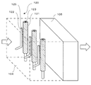
図6は本発明の第2実施形態のガス浄化装置の斜視図であり、その放電気流誘起部104の内部を説明したものである。図6において、100はガス浄化装置を、104は放電気流誘起部を、120は気流を発生させる棒状電極2本からなるプラズマ・アクチュエータを、105は浄化処理部を示す。この浄化処理部105としては、前記第1実施形態に記載した各種の吸着材や分解手段が使用できる。
(2) Second Embodiment (2-1) Configuration of Second Embodiment FIG. 6 is a perspective view of a gas purification device according to a second embodiment of the present invention, and illustrates the inside of the discharge
前記プラズマ・アクチュエータ120は、例えば、図7のような構成を有する。すなわち、第1と第2の放電電極122,123が、少なくとも一方(図では、第2の電極123)が誘電体である絶縁材121で被覆されている。この結果として、外径の異なる2本の棒状の電極122,123が、近接或いは接触して平行に設置され、両電極間に高周波電圧を印加して誘電体バリア放電125を両電極間に発生させるように構成されている。
The
すなわち、図7では、第1の電極122が金属の円筒電極で構成され、第2の電極123が絶縁材121で被覆された金属の対向電極から構成されている。また、第2の電極123を接地とし、第1の電極122に放電用電源103から高周波電圧を印加し放電125を生成する。
That is, in FIG. 7, the
なお、第1及び第2の電極は図7のような円筒形である必要はなく、図8に示したように、扁平な形状でも良い。また、第2の電極を被覆する絶縁材121としても、電極と同様な円柱状でなくとも良く、図8のような紡錘状や他の形状であっても良い。
The first and second electrodes do not have to be cylindrical as shown in FIG. 7, and may be flat as shown in FIG. Further, the insulating
(2−2)第2実施形態の作用
図6から8に示した第1及び第2の電極122,123を備えた放電気流誘起部104からは、図中右方向に向かう流れが誘起され、これらが浄化処理部105へ処理対象のガスを引き込む原動力となる。また、両電極間に発生する放電によって悪臭成分や有害成分などの不純物が分解、除去される。従って、ガス浄化装置の処理能力が向上する。
(2-2) Operation of the Second Embodiment From the discharge
(2−3)第2実施形態の効果
以上の結果より明らかなように、本実施形態により、従来よりも振動、騒音が低く、且つ、処理能力の高いガス浄化装置を提供することができる。特に、第1及び第2の電極122,123を棒状の電極とすることで、板状の電極を使用した前記第1実施形態に比較して、電極の配置や本数の増減に対して柔軟に対応できる利点がある。
(2-3) Effects of the Second Embodiment As is clear from the above results, this embodiment can provide a gas purification device that has lower vibration and noise than the conventional one and has a high processing capacity. In particular, by making the first and
(3)第3実施形態
(3−1)第3実施形態の構成
図9は本発明の第3実施形態のガス浄化装置の斜視図であり、放電気流誘起部104の内部を説明したものである。図9において、100は円筒状をしたガス浄化装置を、104はその前段に設けられて同じく円筒状をした放電気流誘起部を、120は気流を発生させるプラズマ・アクチュエータを、105は同じく円筒状の浄化処理部を示す。
(3) Third Embodiment (3-1) Configuration of Third Embodiment FIG. 9 is a perspective view of a gas purification device according to a third embodiment of the present invention, and illustrates the inside of the discharge
この第3実施形態において、プラズマ・アクチュエータ120は、前記図3から図5において説明した両面に第1及び第2の電極122,123を配置した平板状の絶縁板121を円筒状に湾曲させて構成したものである。なお、本実施形態では、第1の電極122を円筒状とした絶縁板121の内面側に配置し、第2の電極を外面側に配置することで、円筒の内側に気流が誘起されるようにしている。
In the third embodiment, the
この場合、円筒状をしたプラズマ・アクチュエータ120は、気流の流れ方向に沿って複数個配置することもできるし、また、図10に示すように、径の異なる円筒状プラズマ・アクチュエータ120を同軸状に配置しても良い。更に、浄化装置100が角筒状をしている場合には、プラズマ・アクチュエータ120を角筒状とすることも可能である。
In this case, a plurality of
(3−2)第3実施形態の作用
次に、これらの作用について説明する。図9のように、円筒状をしたプラズマ・アクチュエータ120の内面に配置した第1の電極122から絶縁板121の表面側に向かって誘起された放電により、円筒状をしたプラズマ・アクチュエータ120の内壁に沿った気流が誘起され、この気流により浄化対象のガスが浄化装置100の入口から後段の浄化処理部105に送られる。
(3-2) Actions of Third Embodiment Next, these actions will be described. As shown in FIG. 9, the inner wall of the
また、このプラズマ・アクチュエータ120を気流の流れ方向に多段に配置したり、図10のように同軸状に複数個設置することによって、風量を増やすことができる。そして、このプラズマ・アクチュエータ120によって送られた浄化対象ガスは、第1と第2の電極部分の放電によって不純物が分解除去されると共に、浄化処理部105に設けられた浄化処理手段の吸着材や分解手段により更に浄化された後、装置外部に排出される。
Further, the air volume can be increased by arranging the
(3−3)第3実施形態の効果
以上の結果より明らかなように、本実施形態によれば、円筒状の浄化装置100の外壁面近傍にプラズマ・アクチュエータ120を配置することで、浄化装置内に吸入するガスの流れを阻害することなく、気流を誘起することが可能になる。また、気流方向に多段に配置したり、同心円状に複数配置したりすることで、気流をより強力なものとすることが可能になる。
(3-3) Effects of Third Embodiment As is clear from the above results, according to the present embodiment, the purification device is provided by disposing the
更に、プラズマ・アクチュエータ120を円筒状あるいは角筒状とすることで、既存のダクトや排気管の形状に合わせて、浄化装置を作製することが可能になる利点もある。
Further, the
(4)第4実施形態
(4−1)第4実施形態の構成
図11を参照しながら、本発明の第4実施形態を説明する。この第4実施形態は、図4にて説明した並列に配置された平板型のプラズマ・アクチュエータ120の間に、平板に担持された光触媒130を配置したものである。この光触媒の担体は、ほかに、メッシュ、ハニカム、セラミック多孔体でも可能である。なお、プラズマ・アクチュエータ120は、図11の形状に限らず、これまで説明してきたいずれかの実施形態に示したものを適宜選択して使用できる。
(4) Fourth Embodiment (4-1) Configuration of Fourth Embodiment A fourth embodiment of the present invention will be described with reference to FIG. In the fourth embodiment, the
なお、この第4実施形態において、プラズマ・アクチュエータ120や光触媒130の後段に、吸着材やオゾン分解触媒を配置しても良いことは、他の実施形態と同様である。
In the fourth embodiment, an adsorbent and an ozone decomposition catalyst may be disposed after the
(4−2)第4実施形態の作用
次に、これらの作用について説明する。この実施形態においては、プラズマ・アクチュエータ120は、気流を誘起する以外にオゾン等の活性種を生成し、有害物質や悪臭物質を分解する。さらに、放電によって、紫外域から可視域の光を放出する。この光によって、プラズマ・アクチュエータと並んで設置した光触媒を活性化し、有害物質や悪臭物質の分解に寄与する。
(4-2) Operation of Fourth Embodiment Next, these operations will be described. In this embodiment, the
(4−3)第4実施形態の効果
このような構成を有する第4実施形態によれば、プラズマ・アクチュエータ120の放電やそれによって発生したオゾンによる不純物の分解作用と、光触媒130による分解作用とを併用できるので、プラズマ・アクチュエータ120単独の場合に比較し、浄化機能をより高めることができる。
(4-3) Effect of Fourth Embodiment According to the fourth embodiment having such a configuration, the decomposition action of impurities by the discharge of
また、放電気流誘起部104の放電によって発生する光を光触媒の活性化用として利用できるので、光触媒の配置部分に活性化用のランプを設けたり、装置外部から紫外線などを照射する必要もなく、装置の構造が単純化する利点もある。なお、本実施形態は、これらのランプや照射用の窓を設けることを排除するものではない。
Further, since the light generated by the discharge of the discharge
更に、光触媒130のみで不純物の分解を行うようにして、後段に別途吸着材や分解手段などの浄化処理手段を設けない場合には、放電気流誘起部104と浄化処理部とを浄化装置100内の近接した位置に配置することができるので、装置全体の長さ(気流方向の長さ)を小型化することが可能になる。また、放電による不純物の分解処理と酸化触媒などによる浄化処理とを同位置で実施するので、両者の相乗効果により処理能力の高いガス浄化装置を提供することができる。
Further, in the case where impurities are decomposed only by the
(5)他の実施形態
本発明は前記の実施形態に限定されるものではなく、次のような他の実施形態も包含するものである。
(5) Other Embodiments The present invention is not limited to the above-described embodiments, and includes the following other embodiments.
(a) 浄化処理部105の浄化処理手段として吸着材を充填したもの。吸着材の形態は、ハニカム構造であっても、ボール状であっても、ガスの流れを妨げないものであればよい。必要に応じて、さらに後段にオゾン分解触媒を追加し、放電で発生したオゾンを完全に分解する手段を講じても良い。
(a) A material filled with an adsorbent as a purification processing means of the
この実施形態では、放電気流誘起部104で誘起された気流に乗って、有害物質や悪臭物質が運ばれ、後段の浄化処理部105に置かれた吸着材に吸着される。放電が生成したオゾンやラディカル種も吸着され、そこで、有害物質、悪臭成分が酸化分解される。なお、プラズマ・アクチュエータの放電によっても、直接分解される。
In this embodiment, a harmful substance and a malodorous substance are carried on the airflow induced by the discharge
(b) 浄化処理部105に浄化処理手段として光触媒を充填したもの。この光触媒の担体は、メッシュ、平板、ハニカム構造体、セラミック・ボールの何であっても、ガスの流れを妨げないものであればよい。光触媒は、紫外線や可視光を受けて活性になるので、光をあてる工夫が必要である。例えば、浄化処理部105に紫外光と可視光が透過する窓を設けたり、ランプを併用することが好ましい。必要に応じて、さらに後段にオゾン分解触媒を追加し、放電で発生したオゾンを完全に分解する手段を講じても良い。
(b) The
この実施形態では、放電気流誘起部104で誘起された気流に乗って、有害物質や悪臭物質が運ばれ、後段の浄化処理部105に置かれた光触媒によって分解除去される。また、プラズマ・アクチュエータの放電によっても、直接分解される。
In this embodiment, harmful substances and malodorous substances are carried on the airflow induced by the discharge
(c) 浄化処理部105の浄化処理手段として酸化触媒を使用したもの。この酸化触媒の形態はハニカム構造であっても、ボール状であっても、ガスの流れを妨げないものであればよい。必要に応じて、さらに後段にオゾン分解触媒を追加し、放電で発生したオゾンを完全に分解する手段を講じても良い。
(c) A device using an oxidation catalyst as a purification treatment means of the
この実施形態では、放電気流誘起部104で誘起された気流に乗って、有害物質や悪臭物質が運ばれ、後段の浄化処理部105に置かれた酸化触媒によって酸化分解される。なお、プラズマ・アクチュエータの放電によっても、直接分解される。
In this embodiment, harmful substances and malodorous substances are carried on the airflow induced by the discharge
(d) 第4実施形態の光触媒の場合と同様に、吸着材やオゾン分解触媒などの浄化処理手段を放電気流誘起部の近傍(周囲)に配置したもの。
(e) 前記気流誘起部104によるガスの送風を補助するためのファンなどの送風機を設けたもの。
(d) As in the case of the photocatalyst of the fourth embodiment, a purification processing means such as an adsorbent or an ozone decomposition catalyst is arranged in the vicinity (around) the discharge airflow induction section.
(e) Provided with a blower such as a fan for assisting the blowing of gas by the
(f) 装置全体や放電気流発生部などを加熱するもの。この場合、加熱の効果としては、下記2点が考えられる。
・触媒やオゾン分解触媒が活性化され、不純物の処理能力が上がったり、分解途中で中間体として浄化手段(リアクタ)内に残留する成分が少なくなる。
・浄化手段のリフレッシュの効果がある。すなわち、分解途中の中間体で浄化装置内に残留している成分を、完全酸化して(COやCO2にして)外部に吐き出させる。この場合、高温に保って、放電をさせながらしばらく放置することが望ましい。
(f) Equipment that heats the entire device or the discharge airflow generator. In this case, the following two points can be considered as the effect of heating.
-The catalyst and the ozone decomposition catalyst are activated, the impurity processing capacity is increased, and the components remaining in the purification means (reactor) as an intermediate during decomposition are reduced.
・ It has the effect of refreshing the purification means. That is, the components remaining in the purification apparatus as intermediates in the course of decomposition are completely oxidized (CO or CO 2 ) and discharged to the outside. In this case, it is desirable to leave it for a while while discharging at a high temperature.
(g) 高周波の周波数をフィードバックすることにより、放電パワーをコントロールして、風量やオゾン発生量を調節するもの。パワーコントロールは、印加電圧または繰返し周波数を変えることで対応可能であるが、印加電圧による制御は、ある一定以上の電圧を加えないと放電がスタートしなかったり、電圧上昇に対するパワーの増加が非常に大きかったりするので、使いづらい。一方、繰返し周波数に対しては、大体、リニアに変化するので、負荷に応じて、浄化装置の能力をベスト・フィットさせるための手段として、繰返し周波数をフィードバックする機能を盛り込むことができる。 (g) By controlling the discharge power by feeding back the frequency of the high frequency, the air volume and ozone generation amount are adjusted. Power control can be handled by changing the applied voltage or the repetition frequency. However, the control by applied voltage does not start discharging unless a voltage higher than a certain level is applied, or the increase in power with respect to voltage rise is very high. It is big and difficult to use. On the other hand, since the repetition frequency changes substantially linearly, a function of feeding back the repetition frequency can be incorporated as a means for best fitting the capacity of the purification device according to the load.
100…ガス浄化装置
101…吸入口
102…放出口
103…放電用電源
104…放電気流誘起部
105…浄化処理部
106…ダクト
120…平板型のプラズマ・アクチュエータ
121…絶縁板
122…第1の電極
123…第2の電極
124…絶縁材
125…放電
130…光触媒
DESCRIPTION OF SYMBOLS 100 ... Gas purification apparatus 101 ... Inlet port 102 ... Release port 103 ...
Claims (12)
前記第1の電極、誘電体及び第2の電極を、前記第1の電極と第2の電極に高周波電圧を印加した場合にこれらの電極間に発生する誘電体バリア放電により一定方向に気流が流れるように配置してなる放電気流誘起部と、
この放電気流誘起部において誘起された気流が供給される浄化処理部と、この浄化処理部に供給されたガス中の不純物を浄化する浄化処理手段を備えていることを特徴とするガス浄化装置。 A first discharge electrode; a second discharge electrode provided opposite to the first discharge electrode through a dielectric; and a discharge power source for applying a high-frequency voltage to the first and second discharge electrodes. ,
When the high frequency voltage is applied to the first electrode, the dielectric, and the second electrode, the air current is generated in a certain direction due to the dielectric barrier discharge generated between the electrodes. A discharge airflow inducing portion arranged to flow;
A gas purification apparatus comprising: a purification processing unit to which an airflow induced in the discharge airflow induction unit is supplied; and purification processing means for purifying impurities in the gas supplied to the purification processing unit.
Priority Applications (1)
| Application Number | Priority Date | Filing Date | Title |
|---|---|---|---|
| JP2007140942A JP2008289801A (en) | 2007-05-28 | 2007-05-28 | Gas purification device |
Applications Claiming Priority (1)
| Application Number | Priority Date | Filing Date | Title |
|---|---|---|---|
| JP2007140942A JP2008289801A (en) | 2007-05-28 | 2007-05-28 | Gas purification device |
Publications (1)
| Publication Number | Publication Date |
|---|---|
| JP2008289801A true JP2008289801A (en) | 2008-12-04 |
Family
ID=40165155
Family Applications (1)
| Application Number | Title | Priority Date | Filing Date |
|---|---|---|---|
| JP2007140942A Pending JP2008289801A (en) | 2007-05-28 | 2007-05-28 | Gas purification device |
Country Status (1)
| Country | Link |
|---|---|
| JP (1) | JP2008289801A (en) |
Cited By (13)
| Publication number | Priority date | Publication date | Assignee | Title |
|---|---|---|---|---|
| JP2010227877A (en) * | 2009-03-27 | 2010-10-14 | Toshiba Corp | Airflow generating device |
| JP2011139850A (en) * | 2010-01-08 | 2011-07-21 | Toshiba Corp | Air cleaning device and air cleaning method |
| KR101129417B1 (en) * | 2009-11-13 | 2012-03-26 | 한국기계연구원 | Tar or by-product reforming and removing apparatus and method regenerating catalyst using the same |
| JP2014103094A (en) * | 2012-08-08 | 2014-06-05 | National Institute Of Advanced Industrial & Technology | Surface plasma actuator |
| US8747763B2 (en) | 2011-04-13 | 2014-06-10 | Hitachi, Ltd. | Plasma sterilization apparatus |
| JP2014514155A (en) * | 2011-05-10 | 2014-06-19 | コミッサリア ア レネルジー アトミーク エ オ ゼネルジ ザルタナテイヴ | Device for processing gases using surface plasma |
| JP2014116398A (en) * | 2012-12-07 | 2014-06-26 | Toshiba Corp | Cooling apparatus |
| JP2014155917A (en) * | 2013-02-18 | 2014-08-28 | Setekku:Kk | Discharge plasma reactor |
| JP2015182004A (en) * | 2014-03-24 | 2015-10-22 | 株式会社東芝 | Gas treatment apparatus |
| US20170007958A1 (en) * | 2015-07-10 | 2017-01-12 | Kabushiki Kaisha Toshiba | Gas Processing Apparatus |
| US9934944B2 (en) | 2015-07-15 | 2018-04-03 | Kabushiki Kaisha Toshiba | Plasma induced flow electrode structure, plasma induced flow generation device, and method of manufacturing plasma induced flow electrode structure |
| KR102639634B1 (en) * | 2023-07-08 | 2024-02-22 | (주)아하 | DBD optical plasma module for negative pressure and sterilization and purification equipment |
| JP7438657B2 (en) | 2018-08-31 | 2024-02-27 | トヨタ紡織株式会社 | Air purification device and air purification method |
-
2007
- 2007-05-28 JP JP2007140942A patent/JP2008289801A/en active Pending
Cited By (17)
| Publication number | Priority date | Publication date | Assignee | Title |
|---|---|---|---|---|
| JP2010227877A (en) * | 2009-03-27 | 2010-10-14 | Toshiba Corp | Airflow generating device |
| KR101129417B1 (en) * | 2009-11-13 | 2012-03-26 | 한국기계연구원 | Tar or by-product reforming and removing apparatus and method regenerating catalyst using the same |
| JP2011139850A (en) * | 2010-01-08 | 2011-07-21 | Toshiba Corp | Air cleaning device and air cleaning method |
| US8747763B2 (en) | 2011-04-13 | 2014-06-10 | Hitachi, Ltd. | Plasma sterilization apparatus |
| JP2014514155A (en) * | 2011-05-10 | 2014-06-19 | コミッサリア ア レネルジー アトミーク エ オ ゼネルジ ザルタナテイヴ | Device for processing gases using surface plasma |
| US9951800B2 (en) | 2012-08-08 | 2018-04-24 | National Institute Of Advanced Industrial Science And Technology | Surface plasma actuator |
| JP2014103094A (en) * | 2012-08-08 | 2014-06-05 | National Institute Of Advanced Industrial & Technology | Surface plasma actuator |
| JP2018159379A (en) * | 2012-08-08 | 2018-10-11 | 国立研究開発法人産業技術総合研究所 | Fluid machine |
| JP2014116398A (en) * | 2012-12-07 | 2014-06-26 | Toshiba Corp | Cooling apparatus |
| JP2014155917A (en) * | 2013-02-18 | 2014-08-28 | Setekku:Kk | Discharge plasma reactor |
| JP2015182004A (en) * | 2014-03-24 | 2015-10-22 | 株式会社東芝 | Gas treatment apparatus |
| US9468698B2 (en) | 2014-03-24 | 2016-10-18 | Kabushiki Kaisha Toshiba | Gas processing apparatus |
| JP2017018901A (en) * | 2015-07-10 | 2017-01-26 | 株式会社東芝 | Gas treating device |
| US20170007958A1 (en) * | 2015-07-10 | 2017-01-12 | Kabushiki Kaisha Toshiba | Gas Processing Apparatus |
| US9934944B2 (en) | 2015-07-15 | 2018-04-03 | Kabushiki Kaisha Toshiba | Plasma induced flow electrode structure, plasma induced flow generation device, and method of manufacturing plasma induced flow electrode structure |
| JP7438657B2 (en) | 2018-08-31 | 2024-02-27 | トヨタ紡織株式会社 | Air purification device and air purification method |
| KR102639634B1 (en) * | 2023-07-08 | 2024-02-22 | (주)아하 | DBD optical plasma module for negative pressure and sterilization and purification equipment |
Similar Documents
| Publication | Publication Date | Title |
|---|---|---|
| JP2008289801A (en) | Gas purification device | |
| US9138504B2 (en) | Plasma driven catalyst system for disinfection and purification of gases | |
| DK2411058T3 (en) | DEVICE FOR Air decontamination | |
| KR100625425B1 (en) | Discharge device and air purifier | |
| KR20190067633A (en) | Apparatus for sterilization and deodorization of air using Plasma and Photocatalyst | |
| JP5714955B2 (en) | Air conditioner | |
| US20160030622A1 (en) | Multiple Plasma Driven Catalyst (PDC) Reactors | |
| KR101305762B1 (en) | Reclamated Air Cleaner Using Plasma | |
| RU94669U1 (en) | DEVICE FOR SANITARY-HYGIENIC AIR TREATMENT | |
| KR20050019692A (en) | Cleanness unit for air sterilization setting in the air conditioning line | |
| WO2020001068A1 (en) | Air purifier | |
| JP2008014527A (en) | Air conditioner | |
| KR20220099702A (en) | Air cleaning device using atmospheric-pressure plasma | |
| JP2007029896A (en) | Plasma reactor and gas treatment apparatus | |
| CN214009469U (en) | Plasma driving catalyst equipment for air disinfection and purification | |
| JP2006167190A (en) | Air purifier | |
| JP4535748B2 (en) | Air purification device | |
| JP2004350890A (en) | Purifying method and purifier | |
| WO2016147792A1 (en) | Air purifier | |
| JP2006097982A (en) | Range hood | |
| JP2000279492A (en) | Gas cracking structure and gas cracking device and air conditioner using the same | |
| JP2006043550A (en) | Air cleaner | |
| JP2004164918A (en) | Ion generating device | |
| JP2002336343A (en) | Plasma catalyst reactor and air cleaner | |
| CN117006572A (en) | Filter screen sterilizing equipment and air purifier |