JP2012211684A - Pipe joint - Google Patents
Pipe joint Download PDFInfo
- Publication number
- JP2012211684A JP2012211684A JP2011229951A JP2011229951A JP2012211684A JP 2012211684 A JP2012211684 A JP 2012211684A JP 2011229951 A JP2011229951 A JP 2011229951A JP 2011229951 A JP2011229951 A JP 2011229951A JP 2012211684 A JP2012211684 A JP 2012211684A
- Authority
- JP
- Japan
- Prior art keywords
- pipe
- tightening
- ring
- peripheral surface
- tightening ring
- Prior art date
- Legal status (The legal status is an assumption and is not a legal conclusion. Google has not performed a legal analysis and makes no representation as to the accuracy of the status listed.)
- Granted
Links
Images


Classifications
-
- F—MECHANICAL ENGINEERING; LIGHTING; HEATING; WEAPONS; BLASTING
- F16—ENGINEERING ELEMENTS AND UNITS; GENERAL MEASURES FOR PRODUCING AND MAINTAINING EFFECTIVE FUNCTIONING OF MACHINES OR INSTALLATIONS; THERMAL INSULATION IN GENERAL
- F16L—PIPES; JOINTS OR FITTINGS FOR PIPES; SUPPORTS FOR PIPES, CABLES OR PROTECTIVE TUBING; MEANS FOR THERMAL INSULATION IN GENERAL
- F16L37/00—Couplings of the quick-acting type
- F16L37/08—Couplings of the quick-acting type in which the connection between abutting or axially overlapping ends is maintained by locking members
- F16L37/12—Couplings of the quick-acting type in which the connection between abutting or axially overlapping ends is maintained by locking members using hooks, pawls, or other movable or insertable locking members
-
- F—MECHANICAL ENGINEERING; LIGHTING; HEATING; WEAPONS; BLASTING
- F16—ENGINEERING ELEMENTS AND UNITS; GENERAL MEASURES FOR PRODUCING AND MAINTAINING EFFECTIVE FUNCTIONING OF MACHINES OR INSTALLATIONS; THERMAL INSULATION IN GENERAL
- F16L—PIPES; JOINTS OR FITTINGS FOR PIPES; SUPPORTS FOR PIPES, CABLES OR PROTECTIVE TUBING; MEANS FOR THERMAL INSULATION IN GENERAL
- F16L21/00—Joints with sleeve or socket
- F16L21/08—Joints with sleeve or socket with additional locking means
-
- F—MECHANICAL ENGINEERING; LIGHTING; HEATING; WEAPONS; BLASTING
- F16—ENGINEERING ELEMENTS AND UNITS; GENERAL MEASURES FOR PRODUCING AND MAINTAINING EFFECTIVE FUNCTIONING OF MACHINES OR INSTALLATIONS; THERMAL INSULATION IN GENERAL
- F16L—PIPES; JOINTS OR FITTINGS FOR PIPES; SUPPORTS FOR PIPES, CABLES OR PROTECTIVE TUBING; MEANS FOR THERMAL INSULATION IN GENERAL
- F16L33/00—Arrangements for connecting hoses to rigid members; Rigid hose-connectors, i.e. single members engaging both hoses
- F16L33/02—Hose-clips
- F16L33/03—Self-locking elastic clips
-
- F—MECHANICAL ENGINEERING; LIGHTING; HEATING; WEAPONS; BLASTING
- F16—ENGINEERING ELEMENTS AND UNITS; GENERAL MEASURES FOR PRODUCING AND MAINTAINING EFFECTIVE FUNCTIONING OF MACHINES OR INSTALLATIONS; THERMAL INSULATION IN GENERAL
- F16L—PIPES; JOINTS OR FITTINGS FOR PIPES; SUPPORTS FOR PIPES, CABLES OR PROTECTIVE TUBING; MEANS FOR THERMAL INSULATION IN GENERAL
- F16L33/00—Arrangements for connecting hoses to rigid members; Rigid hose-connectors, i.e. single members engaging both hoses
- F16L33/22—Arrangements for connecting hoses to rigid members; Rigid hose-connectors, i.e. single members engaging both hoses with means not mentioned in the preceding groups for gripping the hose between inner and outer parts
- F16L33/227—Arrangements for connecting hoses to rigid members; Rigid hose-connectors, i.e. single members engaging both hoses with means not mentioned in the preceding groups for gripping the hose between inner and outer parts the hose being introduced into or onto the connecting member and automatically locked
-
- F—MECHANICAL ENGINEERING; LIGHTING; HEATING; WEAPONS; BLASTING
- F16—ENGINEERING ELEMENTS AND UNITS; GENERAL MEASURES FOR PRODUCING AND MAINTAINING EFFECTIVE FUNCTIONING OF MACHINES OR INSTALLATIONS; THERMAL INSULATION IN GENERAL
- F16L—PIPES; JOINTS OR FITTINGS FOR PIPES; SUPPORTS FOR PIPES, CABLES OR PROTECTIVE TUBING; MEANS FOR THERMAL INSULATION IN GENERAL
- F16L37/00—Couplings of the quick-acting type
- F16L37/08—Couplings of the quick-acting type in which the connection between abutting or axially overlapping ends is maintained by locking members
- F16L37/084—Couplings of the quick-acting type in which the connection between abutting or axially overlapping ends is maintained by locking members combined with automatic locking
- F16L37/088—Couplings of the quick-acting type in which the connection between abutting or axially overlapping ends is maintained by locking members combined with automatic locking by means of a split elastic ring
Landscapes
- Engineering & Computer Science (AREA)
- General Engineering & Computer Science (AREA)
- Mechanical Engineering (AREA)
- Quick-Acting Or Multi-Walled Pipe Joints (AREA)
- Joints With Sleeves (AREA)
- Mutual Connection Of Rods And Tubes (AREA)
Abstract
【課題】十分なパイプ引抜力を有する管継手を提供する。
【解決手段】C型のクランプ用締付環体5を内層として有し、該弾発締付環体5の外層としてC型のクランプ力増強用弾発外嵌体10を、付加した2重弾発構造のパイプ締付環状ユニットUを、具備する。
【選択図】図2A pipe joint having a sufficient pipe pulling force is provided.
SOLUTION: A double clamp body having a C-type clamping ring 5 as an inner layer and a C-type clamping force-enhancing outer fitting body 10 added as an outer layer of the bullet clamping ring 5 is provided. A pipe tightening annular unit U having a resilient structure is provided.
[Selection] Figure 2
Description
本発明は、管継手に関する。 The present invention relates to a pipe joint.
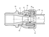
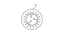
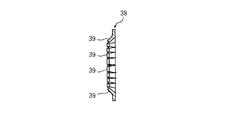
従来から接続したパイプに対する引抜力を強化した管継手が多数提案されてきた。例えば、図14〜図17に示すように、被接続用のパイプ31の端部に挿入される挿入筒部32を有する継手本体33と、上記挿入筒部32の凹周溝34に装着されるシール材35と、上記挿入筒部32に外嵌された上記パイプ31の端部を弾発的な締め付け力F36で締め付けるためのスリット付きの締付環体36と、該締付環体36の弾発力に抗して該締付環体36を拡径するように上記スリットの端部に離脱可能に挟持されて、挿入される上記パイプ31の先端部に当接して離脱する拡径片37と、上記挿入筒部32に外嵌された上記パイプ31の外周面に抜け止め状態に内周面が掛止する抜け止めリング38と、を具備し、該抜け止めリング38の内周側には、周方向に等間隔に切り込み形成された複数個の歯部39が設けられた管継手が公知である(特許文献1参照)。
Many pipe joints have been proposed that have enhanced pull-out force for pipes that have been connected. For example, as shown in FIGS. 14 to 17, the fitting
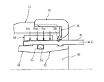
ところで、上述の図14〜図17に示した従来の管継手には、以下のような問題点があった。 (i) 締付環体36によってパイプ31の端部を弾発的な締め付け力F36(図17参照)にて締め付けてパイプ31の矢印G方向への引き抜けを防止せんとしているが引き抜け抑止力が不十分であった。(ii) 締付環体36の締め付け力F36のみでは引き抜け抑止力が不十分であったが故に、さらに、抜け止めリング38を必要とした。(iii) 図14からも判るように、この抜け止めリング38がパイプ31から受ける反力は、袋ナット40及び透明包囲筒体41を経て、さらに螺着部42を介して継手本体33へ伝達されることとなるので、袋ナット40,包囲筒体41,螺着部42等は強度上十分な肉厚を要し、かつ、相互連結強度も必要であった。 (iv) シール材35とシール溝(凹周溝)34を必要とし、このシール材35が無ければ流体の外部漏洩が避けられなかった。 (v) このようにシール材35とシール溝(凹周溝)34を必要としたために、挿入筒部32の肉厚寸法が増加して、挿入筒部32の貫通孔(流路孔)43が小径となり流体通過抵抗が増大する。そこで、本発明は、従来のこのような問題点(i)〜(v)を解決して、パイプの引抜けを確実に防ぐことが可能であり、構造も簡素で、部品点数も減少できて、製作も容易な管継手の提供を目的とする。
Incidentally, the conventional pipe joint shown in FIGS. 14 to 17 described above has the following problems. (i) The end of the
そこで、本発明に係る管継手は、被接続用のパイプの端部に挿入される挿入筒部を有する継手本体と、上記挿入筒部に外嵌された上記パイプの端部を弾発的な締め付け力で締め付けるためのスリット付きのC型の締付環体と、該締付環体の弾発力に抗して該締付環体を拡径するように上記スリットの端部に離脱可能に挟持されて、挿入される上記パイプの先端部を検知して離脱する拡径片と、を具備してなる管継手に於て、上記締付環体に外嵌され、上記弾発的な締め付け力を増大させるC型弾発外嵌体を具備するものである。 In view of this, the pipe joint according to the present invention elastically connects the joint main body having the insertion cylinder portion inserted into the end portion of the pipe to be connected and the end portion of the pipe externally fitted to the insertion cylinder portion. C-type clamping ring with slit for clamping with clamping force, and detachable at the end of the slit to expand the diameter of the clamping ring against the elastic force of the clamping ring And a diameter-expanding piece that detects and removes the tip of the inserted pipe and is externally fitted to the tightening ring, and the elastic It has a C-type bullet external fitting that increases the tightening force.
また、上記締付環体の外周面に対して、上記C型弾発外嵌体の内周面が常時密接するように嵌合している。
また、上記締付環体の外周面に対して、上記C型弾発外嵌体の内周面が、その円弧長の90%以上を非接触状態として、外嵌され、さらに、上記締付環体の上記スリットを形成する両端部の近傍に突設した係止突出子に、上記C型弾発外嵌体のスリット形成端部を係止させたものである。
また、上記C型弾発外嵌体が上記締付環体に外嵌された2重弾発構造により上記パイプの端部を締め付ける増強弾発力によって上記パイプの端部を、上記挿入筒部に高面圧にて圧接させて該挿入筒部にシール材を省略して密封するよう構成したものである。
Further, the inner circumferential surface of the C-type bullet outer fitting is fitted to the outer circumferential surface of the tightening ring so that the inner circumferential surface is always in close contact.
Further, the inner peripheral surface of the C-type bullet outer fitting body is externally fitted to the outer peripheral surface of the tightening ring so that 90% or more of the arc length thereof is in a non-contact state. The slit-forming end portion of the C-type bullet external fitting is locked to a locking protrusion projecting in the vicinity of both end portions forming the slit of the annular body.
Further, the end portion of the pipe is inserted into the insertion tube portion by an enhanced elastic force that tightens the end portion of the pipe by a double bullet structure in which the C-type bullet outer fitting body is fitted on the tightening ring. In this case, the insertion tube portion is sealed with a high surface pressure, and a sealing material is omitted to seal the insertion tube portion.
本発明によれば、前述の従来の問題点(i)〜(v)を解決して、パイプの引抜けを確実に防ぐことが可能であり、構造も簡素で、部品点数も減少できて、製作も容易である。また、挿入筒部に於て、シール溝とシール材を省略することも可能となる場合も多くなり、挿入筒部の貫通孔(流路孔)の径を増大でき、流体通過抵抗も減少できる。 According to the present invention, it is possible to solve the above-mentioned conventional problems (i) to (v) and reliably prevent the pipe from being pulled out, the structure is simple, and the number of parts can be reduced. Manufacture is also easy. In addition, it is often possible to omit the sealing groove and the sealing material in the insertion tube portion, the diameter of the through hole (flow channel hole) of the insertion tube portion can be increased, and the fluid passage resistance can also be reduced. .
以下、図示の実施の形態に基づき本発明を詳説する。図1〜図5は、本発明の実施の一形態を示している。
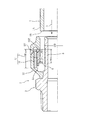
図1と図2に於て、1は被接続用のパイプであって、その端部1Aが矢印Aのように本発明に係る管継手Jに差込まれる。2は継手本体であって、パイプ1の端部1Aの内周面に挿入される挿入筒部3を一体に有している。
Hereinafter, the present invention will be described in detail based on the illustrated embodiment. 1 to 5 show an embodiment of the present invention.
1 and 2,
パイプ1は、内周面が合成樹脂であれば各種の材質・構造のものが使用できるが、好ましくは、PEX(架橋ポリエチレン)、PE(ポリエチレン)、PB(ポリブデン)等の合成樹脂管、あるいは、Al等の金属層を中間層として有する複合管が使用される。また、このパイプ1と管継手Jには給水、給湯等の液体、又は、エア,天然ガス,LPG等の気体が流れる。
そして、挿入筒部3に外嵌されたパイプ端部1Aを(図2と図3と図4に示すように)弾発的な締め付け力で締め付けるためのスリット5A付きのC型の締付環体5と、この締付環体5の弾発力に抗して締付環体5を拡径するようにスリット5Aに離脱可能に挟持された拡径片6を、備えている。この拡径片6は、図1から図2のように挿入されてくるパイプ1の先端部1Bを検知して離脱する。
The
Then, a C-type fastening ring with a
図1のように、拡径片6の一部分6Aは内径方向へ、締付環体5の内面から突出状とし、挿入されてくるパイプ1の先端部1Bが当接することで、図2に示すように、離脱する。
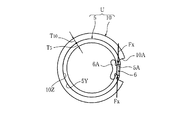
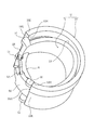
そして、図1〜図5に示すように、締付環体5の外周面には、密嵌状にC型弾発外嵌体10が外嵌され、弾発的な締め付け力を増大させる2重弾発構造のパイプ締付環状ユニットUを構成している。
As shown in FIG. 1, a
As shown in FIGS. 1 to 5, a C-type bullet
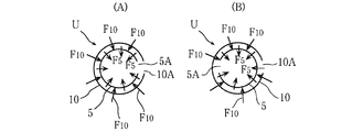
図5に概略図示したように、内層にC型の締付環体5を配設し、外層にC型弾発外嵌体10を配設して、相互に密接した2重弾発構造としたパイプ締付環状ユニットUは、(図2に示す)パイプ端部(1A)を増強弾発力Fuによって弾発的にラジアル内方向へ締め付ける。ここで、締付環体5、C型弾発外嵌体10のラジアル内方向への弾発力を、各々、F5 ,F10とすれば(図5参照)、上記ユニットUの増強弾発力Fuは、Fu=F5 +F10にて示すことができる。
As schematically shown in FIG. 5, a C-
このような2重弾発構造のパイプ締付環状ユニットUの強力な増強弾発力Fuによって、(拡径片6が図2のように離脱した状態下で)パイプ1の端部1Aを、挿入筒部3に対して高面圧で圧接させて、挿入筒部3にシール材(及びシール溝)を全く省略しても、十分な密封作用が得られる。
また、内側(内層)の締付環体5と外側(外層)のC型弾発外嵌体10とを相互に連結する、ピンやリベットやボルトやバンド等の連結部材を省略している。つまり、C型弾発外嵌体10の弾発力F10によって、相互に常時密接状態を保つようにユニット化され、前述のパイプ締付環状ユニットUを構成している。
Due to the strong increased elastic force Fu of the pipe tightening annular unit U having such a double elastic structure, the
Further, connecting members such as pins, rivets, bolts, and bands for mutually connecting the inner (inner layer) fastening
図5(A)及び図3,図4に示すように、内側(内層)の締付環体5のスリット5Aと、外側(外層)のC型弾発外嵌体10のスリット10Aとを、周方向に同じ位置となるように組立てる場合と、図5(B)に示すように周方向に180°反対位置に組立てる場合とがある。
前者の場合には、図3,図4に示すような形状と構成の拡径片6が、ラジアル外方向へ飛散(離脱)しやすいという利点、及び、締付環体5と外嵌体10とがスムースに(軽く)拡径縮径変化しやすい利点がある。後者の場合、拡径片6の形状や構成が(図例以外のものであって)外嵌体10の一部に当てつつ飛散(離脱)させるようなときに有効であり、ラジアル内方向への弾発力Fuが全周に均一としやすいときがある。
As shown in FIG. 5A, FIG. 3 and FIG. 4, the
In the former case, the diameter-enlarged
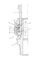
次に、図6〜図11は本発明の他の実施例を示している。
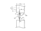
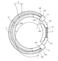
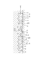
即ち、図1〜図5に於て既述した実施の一形態では、締付環体5の外周面5Yに対して、C型弾発外嵌体10の内周面10Zが常時密接するように嵌合―――密嵌―――している。これに対して、図6〜図11に於ては、締付環体5のスリット5Aを形成する両端部5E,5Eの近傍に、ラジアル外方向へ係止突出子51,51を突設し(合計で4個)、上記C型弾発外嵌体10のスリット形成端部10Eをこの係止突出子51,51に係止させることによって、C型弾性外嵌体10の内周面10Zは、その内周面10Zの円弧長L10の90%〜 100%を締付環体5の外周面5Yに対して非接触状態として、C型弾発外嵌体10は締付環体5に外嵌されている。
ここで、内周面10Zの 100%が非接触状態とは、図6及び図9のように、C型弾発外嵌体10のスリット10Aを形成する最端面10G、及び/又は、最端面内側角部10Hが強く接触(圧接)した状態である。
6 to 11 show another embodiment of the present invention.
That is, in the embodiment described above with reference to FIGS. 1 to 5, the inner
Here, 100% of the inner
また、図6,図8,図9からも明らかなように、90%以上 100%未満では、(上述した最端面10G、及び/又は、角部10Hが圧接すると共に、)C型弾発外嵌体10の両端部10E,10Eの近傍の内面が、締付環体5の外周面5Yに接触している。そして、両端部10E,10Eから、中間部位へ周方向から近づくにつれて、間隙Gがしだいに増加し、この間隔Gは新月(乃至三ケ月)状である。
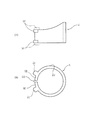
ところで、4個の係止突出子51は、図10(A)の2点鎖線、及び、図6,図7,図11に示した具体例では、折曲塑性加工によって形成され、端部5Eの幅寸法よりも側外方へ突出して形成されている。あるいは、鋳造等によって、図10(A)の実線、及び、図10(B),図9に示したように、端部5Eの幅寸法内で突出させるも好ましい。
Further, as is apparent from FIGS. 6, 8, and 9, when the ratio is 90% or more and less than 100% (the
By the way, the four locking
このように、図6〜図11に示した実施の形態のように、締付環体5の外周面5Yに対して、C型弾発外嵌体10の内周面10Zを、円弧長L10の90%以上を非接触状態として、間隙Gを形成したことにより、次のような利点がある。即ち、図3〜図5に於ては、C型弾発外嵌体10からラジアル内方向への大きい弾発力F10が、図5に示す如く作用し、締付環体5の外周面5Yと、C型弾発外嵌体10の内周面10Zが(極めて)大きな面圧力をもって密接(圧接)し、それに伴って、締付環体5とC型弾発外嵌体10の相互の摩擦力が過大となり、図1と図3に示したパイプ未挿入状態(未接続状態)から図2に示すパイプ挿入状態(接続状態)に、スムーズに変化できない場合が予想される。つまり、上記相互の摩擦力は、(μ×F10)で示されるが、外周面5Yと内周面10Zの表面粗さや状況によっては、摩擦係数μが過大であり、かつ、弾発力F10も、C型弾発外嵌体10の肉厚や幅寸法が大きいときには、過大であり、密嵌した積層二重構造のユニットUがスムースに縮径できない場合も予想される。
Thus, as in the embodiment shown in FIGS. 6 to 11, the inner
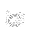
図6〜図11の実施の形態では、このような問題を見事に解決して、図8に示すように、C型弾発外嵌体10からは、締付環体5の外周面5Yへは、(図5に示したラジアル内方向の弾発力F10が作用せずに、代りに)接線方向の大きな弾発力F100 を、係止突出子51,51に集中的に与える。
特に、パイプ1の外径公差の大小等に応じて、パイプ締付環状ユニットUがスムーズに縮径自在であり、図6〜図11の実施の形態の管継手は、一層の改良が加えられていると言える。なお、上述の間隙Gを常時有する以外は、図1と図2に示したところの構成は、図6〜図11の実施の形態の構成と同様である。
In the embodiment of FIGS. 6 to 11, such a problem is solved brilliantly, and as shown in FIG. 8, from the C-type bullet
In particular, the pipe tightening annular unit U can be smoothly reduced in diameter according to the outer diameter tolerance of the
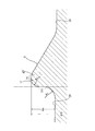
次に、図12は図2の要部拡大図であるが、この図12と図1,図2に於て、挿入筒部3の外周面には、(従来例の図14,図17に示したような)シール溝(凹周溝)34及びシール材35を省略して、複数本の低い(三角状の)係止突条8を独立円環状に突設している。図5(A)(B)又は、図8に示した弾発力による、パイプ端部1Aへの締め付け力によって、パイプ端部1Aの内周面に係止突条8を食い込ませて、矢印E方向へのパイプ抜けを阻止すると共に流体の外部漏洩を防止する。即ち、2重構造としたパイプ締付環状ユニットUの増強弾発力Fuによって、パイプ1の端部内周面に係止突条8を食い込ませて、抜け止め兼密封作用をなさしめている。
Next, FIG. 12 is an enlarged view of the main part of FIG. 2. In FIG. 12, FIG. 1, and FIG. 2, the outer peripheral surface of the
本発明に於て、係止突条8の本数は、3本〜9本程度が好ましく(特に、4〜6本が望ましく)、そのピッチP1 は2mm以下の細かいピッチとする。この際、締付環体5の幅寸法W5 の大小に対応して、係止突条8の本数を増減させるのが良い。また、係止突条8が低いとは、高さ寸法H8 が、 0.1mm〜 0.3mmであると定義する。(図1,図2,図12では9本の場合を示している。)
さらに、挿入筒部3の外周面に突設された複数本の低い係止突条8の軸心方向中間位置には、低い丸山型のシール用丸突条9が配設されている。この丸山型のシール用丸突条9が低いとは、その高さ寸法H9 が 0.1mm〜 0.3mmであると定義する。このように、係止突条8とシール用丸突条9の高さ寸法H8 ,H9 は略等しく設定され、従来公知のタケノ子状係止突条よりも十分に低く設定し、しかも、ピッチP1 は、上記2mm以下として、従来公知のタケノコ状係止突条よりも極めて小さく設定している。
In the present invention, the number of the locking
Further, a low round mountain-shaped sealing round ridge 9 is disposed at an intermediate position in the axial direction of a plurality of
また、図12に示すように、係止突条8,8相互の基本(間隔)ピッチP1 に対して、シール用丸突条9と隣り合う係止突条8Aとの間のピッチP2 ,P3 を、大きく設定する。後者のピッチP2 ,P3 とを同一としても良いが、僅かに差を設けても良い。
Further, as shown in FIG. 12, with respect to the basic (interval) pitch P 1 between the locking
仮に、極めて大きい引抜力が矢印E方向に瞬間的に作用した際には、多数の係止突条8を越えてパイプ1の内面が矢印E方向へ移動するが、上記基本ピッチP1 の移動で再び係止突条8が元の三角凹溝13に係止すると想定され、図12中に矢印E′,E′で示すように基本ピッチP1 だけ移動する。
このとき、一ピッチ分だけ矢印E′のように移動した凹溝13が存在しない平坦円周面が、丸突条9に対応して丸い凹状に弾性変形して密接状態となり、しかも、摩耗傷のない上記平坦円周面が丸い凹状に弾性変形するので、流体の外部漏洩が生じず、安定した密封性を発揮する。
If, very large when the pullout force is applied instantaneously to the arrow E direction is a number of the inner surface of the
At this time, the flat circumferential surface without the
そして、係止突条8は、図12に示すように、管継手内方側に軸心直交状の辺18を有する直角三角形とするのが望ましい。
あるいは、図13の拡大図に示す如く、係止突条8としては、軸心直交状の鉛直部16を有すると共に、頂部17は、アール部R1 ,R2 と平坦辺19とを有する、平坦付丸型頂部、又は、図示省略の平坦辺19を省略の丸型の頂部を有する形状とするも望ましい。このような形状とすると、鍛造や鋳造等にて形成が容易となる利点があり、さらには、図12にて説明した丸突条9を省略して、シール(密封)機能を兼用の抜け止め機能を発揮する利点もある。なお、鉛直部16の付根隅部にもアール部R3 を形成するのが、上記鍛造や鋳造等にての形成が容易となるので好ましい。
さらに追加説明すれば、図1〜図5、及び、図6,図7,図11に於て、拡径片6は高剛性の鋼材等から成り、図1のパイプ未挿入状態では、パイプ1の外径よりも僅かに大きな内径寸法に締付環体5の内径を拡大している。
As shown in FIG. 12, the locking
Alternatively, as shown in the enlarged view of FIG. 13, the locking
1 to FIG. 5, FIG. 6, FIG. 7, and FIG. 11, the diameter-expanding
2重構造であるパイプ締付環状ユニットUは、内側の締付環体5を、いわば正確な真円に近い形状に作製すると共に、外側のC型弾発外嵌体10は強力な弾発力F10又はF100 を発揮させるように幅寸法W10を締付環体5の幅寸法W5 よりも大に設定するのが望ましい。さらには、外嵌体10の肉厚寸法T10を締付環体5の肉厚寸法T5 よりも大きく設定するのが望ましい。
2重構造であるパイプ締付環状ユニットUは、内側(内層)の締付環体5は、(1重の厚肉のものと比較して)バネ鋼材等をC型に塑性加工が容易であり、かつ、正確な真円状とすることも容易である。他方、外側(外層)の弾発外嵌体10も、(1重の厚肉のものと比較して)バネ鋼材等にてC型に塑性加工が容易であると共に、真円度は、それ程、厳密でなくて済むので、作製が容易で、十分に幅寸法W10と肉厚寸法T10を大きくしても、作製可能となるという利点を有する。
The pipe tightening annular unit U, which has a double structure, produces the
The pipe tightening annular unit U having a double structure is easy to plastically process the inner (inner layer) tightening
しかも、内側(内層)の締付環体5のみの構成について考察すれば、(図3と図4と図6と図7に於て、外嵌体10が存在しないとすれば、)軸心方向(幅寸法W5 の方向)に僅かに円錐状(テーパ状)に、拡径片6の存在によって変形する。つまり、拡径片6は、軸心方向(幅寸法W5 の方向)の中央ではなくて、図4,図7の左端側に偏在するため、弾性的に拡径した締付環体5は、図4,図7の左側から右側へ僅かに縮径するテーパ状に変形し、パイプ1のスムースな挿入を阻害する虞がある。しかしながら、図4,図7と図1に示す如く、外側(外層)の弾発外嵌体10は、図4,図7,図1の左方向(管継手内方向)に、拡径片6、及び、締付環体5の内端15より延伸状に配設されていて、その幅寸法W10の中央近傍に拡径片6を配設可能であるので、環状ユニットUの内径―――即ち、締付環体5の内径―――が、管継手内方向へ拡大するテーパ状(円錐状)となることを防止できる。
Moreover, if only the configuration of the inner (inner layer)
例えば、本発明に係る管継手Jの適用されるパイプ1の外径を、10mm〜30mmとした場合に、図3と図4,図7に於て、拡径片6を挟圧保持する挟圧力(弾発力)Fxは、200kg〜 800kgと極めて大きい。特に、図12に示したように、シール材を省略して密封を確実に行うには、係止突条8及びシール用丸突条9が十分にパイプ内周面に食い込む必要があり、既述のユニットUの弾発力Fu(=F5 +F10)を、十分に大きくせねばならないため、上記挟圧力(弾発力)Fxを、 200kg〜 800kgと極めて大きく設定せねばならない。
For example, when the outer diameter of the
そこで、従来例の図14〜図17に示したような一枚の素材(バネ鋼帯板)からなる締付環体36では、従来は全く不可能と考えられていた上述の 200kg〜 800kgもの挟圧力を、本発明によって、初めて達成できたといえる。
言い換えると、特に厚さ寸法の大きいバネ鋼帯板を、内径を10mm強〜30mm強の小径筒型に塑性変形させようとすれば、(降伏点を越えて)製作中に破壊してしまう問題、真円状に加工することが至難であるという問題、及び、径寸法の変化に伴って弾発力(締め付け力)が極端に大小変化してしまうという問題があり、従来から、不可能と考えられていたのである。
Therefore, with the tightening
In other words, if a spring steel strip with a particularly large thickness is plastically deformed into a small-diameter cylindrical mold with an inner diameter of just over 10 mm to over 30 mm, it will break during production (beyond the yield point). , There is a problem that it is difficult to process into a perfect circle, and there is a problem that the resilience (tightening force) changes extremely with the change of the diameter dimension, It was thought.
また、図1と図2に於て、12はカバーであり、離脱した締付環体5が収納される空間を有し、透明樹脂とするのが好ましく、外から目視にて拡径片6が離脱したか否かを確認できる。そして、図1,図2から明らかなように、従来例の図14〜図17に図示した抜け止めリング38を全く省略している。従って、図14〜図17では、パイプ31の外周面に食い込んだ抜け止めリング38がパイプ31から受ける軸心方向の大きな抜け力を、カバー(包囲筒体)41によって受け持つ必要があり、螺着部42等にて強固に継手本体33に連結せねばならなかった。これに対し、本発明では、強度はほとんど必要なくなり、継手本体2に対して、簡易な連結を行うのみで十分であり、カバー12自体も薄い樹脂で済む。
In FIGS. 1 and 2,
ところで、内層側を成す締付環体5の幅寸法W5 について述べると、挿入筒部3の外径寸法をDとすれば、
0.4・D≦W5 ≦ 0.9・D
とする。特に好ましいのは、
0.6・D≦W5 ≦ 0.8・D
とすることであり、例えば、D=13mmではW5 =9mmとし、D=17mmではW5 =11mm等に設定する。
上記範囲内に幅寸法W5 が設定されることにより、確実に各係止突条8がパイプ1の内周面に食い込むと共に、パイプ1の内周面が、突条8と突条8の間の谷底面20に当接できる。さらに、突条8の本数が少なくて済み、同一の弾発力Fuから得られる各突条8のパイプ内周面への食い込み力(圧接面圧力)が大きくできる。なお、締付環体5の幅寸法W5 を図10(A)と図11に示したように周方向に変化している場合は、上記幅寸法W5 は平均値を採用する。
なお、本発明は、図1,図2に例示した雄ネジアダプター型に限らず、雌ネジアダプターやソケットやチーズ等の各種の形式の管継手に応用自由である。
By the way, when the width dimension W 5 of the
0.4 ・ D ≦ W 5 ≦ 0.9 ・ D
And Particularly preferred is
0.6 ・ D ≦ W 5 ≦ 0.8 ・ D
For example, when D = 13 mm, W 5 = 9 mm, and when D = 17 mm, W 5 = 11 mm or the like.
By setting the width dimension W 5 within the above range, each locking
The present invention is not limited to the male screw adapter type illustrated in FIGS. 1 and 2, and can be freely applied to various types of pipe joints such as a female screw adapter, a socket, and cheese.
本発明は以上述べたように、被接続用のパイプ1の端部1Aに挿入される挿入筒部3を有する継手本体2と、上記挿入筒部3に外嵌された上記パイプ1の端部1Aを弾発的な締め付け力で締め付けるためのスリット5A付きのC型の締付環体5と該締付環体5の弾発力に抗して該締付環体5を拡径するように上記スリット5Aの端部に離脱可能に挟持されて、挿入される上記パイプ1の先端部1Bを検知して離脱する拡径片6と、を具備してなる管継手に於て、上記締付環体5に外嵌され、上記弾発的な締め付け力を増大させるC型弾発外嵌体10を具備する構成であるので、締付環体5と弾発外嵌体10とは、各々、バネ鋼等から破損を生じない範囲内で、十分に小径(例えば、内径10mm〜30mm)の円筒形に加工して後に、内層と外層を成すように嵌合して2重構造にユニット化できるので、従来、不可能と考えられていた強大な締め付け弾発力をもって、パイプ1を締め付けて、大きな引抜け力に耐え、かつ、挿入筒部3のシール材も省略可能となる。そして、従来の抜け止めリング38(図14〜図17参照)を省略可能となり、管継手の構成が簡略化される。また、カバー12も強度を必要としない薄肉のものとでき、継手本体2に対する連結強度も弱いもので済む。
As described above, the present invention has a
また、図14〜図17に示した従来例では、抜け止めリング38及びシール材35のいずれもが、パイプ挿入抵抗となり、挿入作業がスムースでなかったが、本発明では、両者が省略可能となって、拡径片6にパイプ先端(内端)15が当たるまで抵抗なくスムースに挿入できる。これによって、挿入未完了で施工を止めることがなくなる。しかも、パイプ1を手で引張れば、挿入未完了(不完全接続)ならばパイプ1が引き抜けてくるので、挿入未完了に気付くという利点がある。
また、本発明では、パイプ1挿入によって、拡径片6が飛んでいない場合(不完全接続)では、検査時に必ず漏水を発生し、容易に施工未完了(不完全接続)を発見できる利点がある。
Further, in the conventional example shown in FIGS. 14 to 17, both the retaining
Moreover, in this invention, when the diameter-expanded
また、上記締付環体5の外周面5Yに対して、上記C型弾発外嵌体10の内周面10Zが常時密接するように嵌合しているので、部品の製作、及び、組立てが容易である。
また、上記締付環体5の外周面5Yに対して、上記C型弾発外嵌体10の内周面10Zが、その円弧長L10の90%以上を非接触状態として、外嵌され、さらに、上記締付環体5の上記スリット5Aを形成する両端部5E,5Eの近傍に突設した係止突出子51に、上記C型弾発外嵌体10のスリット形成端部10Eを係止させた構成であるので、強力なクランプ力を発揮できるにかかわらず、スムースに縮径・拡径が行われ、パイプ1の外径寸法のバラツキに対応(適用)可能であり、かつ、無駄な摩擦損失を生ずることなく、C型弾発外嵌体の弾発力F100 を締付環体5に付加できる。
Further, since the inner
Further, the outer
また、上記C型弾発外嵌体10が上記締付環体5に外嵌された2重弾発構造により上記パイプ1の端部1Aを締め付ける増強弾発力Fuによって上記パイプ1の端部1Aを、上記挿入筒部3に高面圧にて圧接させて該挿入筒部3にシール材を省略して密封するよう構成したので、挿入筒部3の肉厚寸法を減少でき、これに伴って、挿入筒部3の貫通孔を十分に大きく形成でき、流体通過抵抗の増加を防止できる。
Further, the end portion of the
1 パイプ
1A 端部
1B 先端部
3 挿入筒部
5 締付環体
5A スリット
5E 端部
5Y 外周面
6 拡径片
10 C型弾発外嵌体
10E 端部
10Z 内周面
51 係止突出子
Fu 増強弾発力
F10 弾発力
F100 弾発力
G 間隙
L10 円弧長
DESCRIPTION OF
10 C-type bullet external fitting
10E end
10Z inner circumference
51 Locking protrusion Fu Increased resilience F 10 resilience F 100 resilience G Gap L 10 Arc length
Claims (4)
上記締付環体(5)に外嵌され、上記弾発的な締め付け力を増大させるC型弾発外嵌体(10)を具備することを特徴とする管継手。 A joint body (2) having an insertion cylinder part (3) inserted into the end part (1A) of the pipe (1) to be connected, and the pipe (1) externally fitted to the insertion cylinder part (3) C-shaped tightening ring (5) with a slit (5A) for tightening the end (1A) of the ring with a resilient tightening force, and resisting the resilient force of the tightening ring (5) The clamp ring (5) is detachably held at the end of the slit (5A) so as to expand the diameter, and the tip (1B) of the pipe (1) to be inserted is detected and detached. In the pipe joint comprising the expanded diameter piece (6),
A pipe joint comprising a C-type elastic outer fitting (10) that is fitted on the tightening ring (5) and increases the elastic tightening force.
Priority Applications (8)
| Application Number | Priority Date | Filing Date | Title |
|---|---|---|---|
| JP2011229951A JP4906973B1 (en) | 2011-03-22 | 2011-10-19 | Pipe fitting |
| US14/001,568 US20140070531A1 (en) | 2011-03-22 | 2012-03-14 | Pipe joint |
| KR1020137021932A KR20140008346A (en) | 2011-03-22 | 2012-03-14 | Pipe joint |
| CA2825807A CA2825807C (en) | 2011-03-22 | 2012-03-14 | Pipe joint |
| PCT/JP2012/056583 WO2012128152A1 (en) | 2011-03-22 | 2012-03-14 | Pipe joint |
| CN201280014084.3A CN103429943B (en) | 2011-03-22 | 2012-03-14 | Pipe joint |
| EP12760667.1A EP2690337A4 (en) | 2011-03-22 | 2012-03-14 | PIPE JOINT |
| SG2013056940A SG192149A1 (en) | 2011-03-22 | 2012-03-14 | Pipe joint |
Applications Claiming Priority (3)
| Application Number | Priority Date | Filing Date | Title |
|---|---|---|---|
| JP2011062383 | 2011-03-22 | ||
| JP2011062383 | 2011-03-22 | ||
| JP2011229951A JP4906973B1 (en) | 2011-03-22 | 2011-10-19 | Pipe fitting |
Publications (2)
| Publication Number | Publication Date |
|---|---|
| JP4906973B1 JP4906973B1 (en) | 2012-03-28 |
| JP2012211684A true JP2012211684A (en) | 2012-11-01 |
Family
ID=46060774
Family Applications (1)
| Application Number | Title | Priority Date | Filing Date |
|---|---|---|---|
| JP2011229951A Active JP4906973B1 (en) | 2011-03-22 | 2011-10-19 | Pipe fitting |
Country Status (8)
| Country | Link |
|---|---|
| US (1) | US20140070531A1 (en) |
| EP (1) | EP2690337A4 (en) |
| JP (1) | JP4906973B1 (en) |
| KR (1) | KR20140008346A (en) |
| CN (1) | CN103429943B (en) |
| CA (1) | CA2825807C (en) |
| SG (1) | SG192149A1 (en) |
| WO (1) | WO2012128152A1 (en) |
Cited By (2)
| Publication number | Priority date | Publication date | Assignee | Title |
|---|---|---|---|---|
| JP2019530839A (en) * | 2016-10-14 | 2019-10-24 | ノルマ ジャーマニー ゲーエムベーハー | Fitting and fitting assembly and method of manufacturing a fitting |
| JP2021127776A (en) * | 2020-02-12 | 2021-09-02 | 株式会社イノアック住環境 | Hose fixing structure |
Families Citing this family (11)
| Publication number | Priority date | Publication date | Assignee | Title |
|---|---|---|---|---|
| EP2893238A4 (en) * | 2012-09-07 | 2016-08-31 | Famous Ind Inc | COUPLINGS AND SEALED TRANSVERSE LOCK HOSE |
| JP2014219052A (en) * | 2013-05-08 | 2014-11-20 | 日本ピラー工業株式会社 | Pipe connecting device |
| US10859194B2 (en) | 2013-05-20 | 2020-12-08 | Steere Enterprises, Inc. | Clean air duct and retaining clip and assembly thereof |
| US9664321B2 (en) | 2013-05-20 | 2017-05-30 | Steere Enterprises, Inc. | Clean air duct and retaining clip and assembly thereof |
| JP5498617B1 (en) * | 2013-11-14 | 2014-05-21 | 井上スダレ株式会社 | Pipe fitting |
| KR102411134B1 (en) * | 2014-04-24 | 2022-06-20 | 헨 게엠베하 운트 콤파니 카게. | Connector assembly |
| ES2557333B1 (en) * | 2014-07-25 | 2016-09-14 | Ignacio Santiago De La Sota | Quick connector of flexible tubes |
| JP6294986B1 (en) * | 2017-03-24 | 2018-03-14 | 日東工器株式会社 | Fitting for straight pipe |
| WO2020125969A1 (en) * | 2018-12-19 | 2020-06-25 | Oetiker Schweiz Ag | Spring clamp |
| CN111734825B (en) * | 2020-05-20 | 2022-07-22 | 上海巨乾工贸有限公司 | Constant pressure impels extrusion sealing ring |
| US11882984B1 (en) | 2023-03-31 | 2024-01-30 | Emerson Electric Co. | Vacuum conduit attachment tools |
Citations (5)
| Publication number | Priority date | Publication date | Assignee | Title |
|---|---|---|---|---|
| JPS6127387A (en) * | 1984-07-05 | 1986-02-06 | ラスムツセン ジイエムビイエイチ | hose fittings |
| JP2001027375A (en) * | 1999-07-16 | 2001-01-30 | Higashio Mech Co Ltd | Joint for resin pipe |
| JP2002031282A (en) * | 2000-07-11 | 2002-01-31 | Higashio Mech Co Ltd | Pipe fittings |
| JP2006242349A (en) * | 2005-03-04 | 2006-09-14 | Ck Metals Co Ltd | Pipe joint |
| JP2006242348A (en) * | 2005-03-04 | 2006-09-14 | Ck Metals Co Ltd | Pipe joint |
Family Cites Families (10)
| Publication number | Priority date | Publication date | Assignee | Title |
|---|---|---|---|---|
| US4643466A (en) * | 1984-03-29 | 1987-02-17 | American Cast Iron Pipe Company | Pipe joint assembly with snap ring and associated method |
| JP2677291B2 (en) * | 1988-09-14 | 1997-11-17 | ブリヂストンフローテック株式会社 | Pipe fittings |
| GB2326920A (en) * | 1997-07-01 | 1999-01-06 | Rasmussen Gmbh | Clamp for clamping a hose on a pipe portion |
| JP3405966B2 (en) * | 2000-02-07 | 2003-05-12 | 東尾メック株式会社 | Pipe fitting |
| JP2005291420A (en) * | 2004-04-01 | 2005-10-20 | Sekisui Chem Co Ltd | Pipe fitting |
| JP3754059B1 (en) * | 2004-11-29 | 2006-03-08 | 井上スダレ株式会社 | Pipe fitting |
| JP2008286259A (en) * | 2007-05-16 | 2008-11-27 | Higashio Mech Co Ltd | Pipe joint |
| JP2008286260A (en) * | 2007-05-16 | 2008-11-27 | Higashio Mech Co Ltd | Pipe fitting |
| DE102007025931B3 (en) * | 2007-06-02 | 2009-01-15 | Uponor Innovation Ab | Clamp fitting for a pipe |
| CN102330723A (en) * | 2010-07-13 | 2012-01-25 | 新秩序投资119股份有限公司 | Pipe fitting |
-
2011
- 2011-10-19 JP JP2011229951A patent/JP4906973B1/en active Active
-
2012
- 2012-03-14 EP EP12760667.1A patent/EP2690337A4/en not_active Withdrawn
- 2012-03-14 US US14/001,568 patent/US20140070531A1/en not_active Abandoned
- 2012-03-14 CA CA2825807A patent/CA2825807C/en not_active Expired - Fee Related
- 2012-03-14 WO PCT/JP2012/056583 patent/WO2012128152A1/en not_active Ceased
- 2012-03-14 CN CN201280014084.3A patent/CN103429943B/en not_active Expired - Fee Related
- 2012-03-14 KR KR1020137021932A patent/KR20140008346A/en not_active Withdrawn
- 2012-03-14 SG SG2013056940A patent/SG192149A1/en unknown
Patent Citations (5)
| Publication number | Priority date | Publication date | Assignee | Title |
|---|---|---|---|---|
| JPS6127387A (en) * | 1984-07-05 | 1986-02-06 | ラスムツセン ジイエムビイエイチ | hose fittings |
| JP2001027375A (en) * | 1999-07-16 | 2001-01-30 | Higashio Mech Co Ltd | Joint for resin pipe |
| JP2002031282A (en) * | 2000-07-11 | 2002-01-31 | Higashio Mech Co Ltd | Pipe fittings |
| JP2006242349A (en) * | 2005-03-04 | 2006-09-14 | Ck Metals Co Ltd | Pipe joint |
| JP2006242348A (en) * | 2005-03-04 | 2006-09-14 | Ck Metals Co Ltd | Pipe joint |
Cited By (4)
| Publication number | Priority date | Publication date | Assignee | Title |
|---|---|---|---|---|
| JP2019530839A (en) * | 2016-10-14 | 2019-10-24 | ノルマ ジャーマニー ゲーエムベーハー | Fitting and fitting assembly and method of manufacturing a fitting |
| US11215305B2 (en) | 2016-10-14 | 2022-01-04 | Norma Germany Gmbh | Connector and connector assembly and method for producing a connector |
| JP2021127776A (en) * | 2020-02-12 | 2021-09-02 | 株式会社イノアック住環境 | Hose fixing structure |
| JP7512044B2 (en) | 2020-02-12 | 2024-07-08 | 株式会社イノアック住環境 | Hose fixing structure |
Also Published As
| Publication number | Publication date |
|---|---|
| JP4906973B1 (en) | 2012-03-28 |
| CN103429943B (en) | 2015-06-17 |
| KR20140008346A (en) | 2014-01-21 |
| CN103429943A (en) | 2013-12-04 |
| CA2825807A1 (en) | 2012-09-27 |
| WO2012128152A1 (en) | 2012-09-27 |
| SG192149A1 (en) | 2013-09-30 |
| EP2690337A1 (en) | 2014-01-29 |
| US20140070531A1 (en) | 2014-03-13 |
| CA2825807C (en) | 2018-07-24 |
| EP2690337A4 (en) | 2014-10-01 |
Similar Documents
| Publication | Publication Date | Title |
|---|---|---|
| JP4906973B1 (en) | Pipe fitting | |
| JP5311795B2 (en) | Pipe fitting | |
| JP4730972B2 (en) | Pipe fittings for plastic resin pipes | |
| JP2016017543A (en) | Pipe fitting | |
| WO2013168306A1 (en) | Pipe joint | |
| JP5269178B2 (en) | How to assemble pipe fittings | |
| JP5537982B2 (en) | Pipe fitting | |
| JP2008286259A (en) | Pipe joint | |
| WO2015156198A1 (en) | Pipe fitting | |
| JP2011047467A (en) | Sprinkler unwinding piping | |
| JP6343131B2 (en) | Fitting | |
| JP2006105269A (en) | Pipe joint | |
| JP4939826B2 (en) | How to assemble pipe fittings | |
| JP5818855B2 (en) | Pipe fitting | |
| JP5736202B2 (en) | Pipe fitting | |
| JP2008038924A (en) | Pipe joint | |
| CN100529499C (en) | Pipe joint | |
| CN108443608B (en) | Pipe joint | |
| JP6448229B2 (en) | Fitting | |
| JP7486786B2 (en) | Pipe Fittings | |
| JP2022169971A (en) | Pipe joint structure | |
| JP6294986B1 (en) | Fitting for straight pipe | |
| CN214999953U (en) | Bellows joint | |
| JP5410469B2 (en) | Pipe fitting | |
| JP4100810B2 (en) | Fitting for flexible tube |
Legal Events
| Date | Code | Title | Description |
|---|---|---|---|
| TRDD | Decision of grant or rejection written | ||
| A01 | Written decision to grant a patent or to grant a registration (utility model) |
Free format text: JAPANESE INTERMEDIATE CODE: A01 |
|
| A61 | First payment of annual fees (during grant procedure) |
Free format text: JAPANESE INTERMEDIATE CODE: A61 Effective date: 20120110 |
|
| FPAY | Renewal fee payment (event date is renewal date of database) |
Free format text: PAYMENT UNTIL: 20150120 Year of fee payment: 3 |
|
| R150 | Certificate of patent or registration of utility model |
Ref document number: 4906973 Country of ref document: JP Free format text: JAPANESE INTERMEDIATE CODE: R150 Free format text: JAPANESE INTERMEDIATE CODE: R150 |
|
| R250 | Receipt of annual fees |
Free format text: JAPANESE INTERMEDIATE CODE: R250 |
|
| R250 | Receipt of annual fees |
Free format text: JAPANESE INTERMEDIATE CODE: R250 |
|
| R250 | Receipt of annual fees |
Free format text: JAPANESE INTERMEDIATE CODE: R250 |
|
| R250 | Receipt of annual fees |
Free format text: JAPANESE INTERMEDIATE CODE: R250 |
|
| R250 | Receipt of annual fees |
Free format text: JAPANESE INTERMEDIATE CODE: R250 |
|
| R250 | Receipt of annual fees |
Free format text: JAPANESE INTERMEDIATE CODE: R250 |
|
| R250 | Receipt of annual fees |
Free format text: JAPANESE INTERMEDIATE CODE: R250 |
|
| R250 | Receipt of annual fees |
Free format text: JAPANESE INTERMEDIATE CODE: R250 |
|
| R250 | Receipt of annual fees |
Free format text: JAPANESE INTERMEDIATE CODE: R250 |
|
| R250 | Receipt of annual fees |
Free format text: JAPANESE INTERMEDIATE CODE: R250 |
|
| R250 | Receipt of annual fees |
Free format text: JAPANESE INTERMEDIATE CODE: R250 |
|
| R250 | Receipt of annual fees |
Free format text: JAPANESE INTERMEDIATE CODE: R250 |