JP2005291420A - Pipe fitting - Google Patents
Pipe fitting Download PDFInfo
- Publication number
- JP2005291420A JP2005291420A JP2004109046A JP2004109046A JP2005291420A JP 2005291420 A JP2005291420 A JP 2005291420A JP 2004109046 A JP2004109046 A JP 2004109046A JP 2004109046 A JP2004109046 A JP 2004109046A JP 2005291420 A JP2005291420 A JP 2005291420A
- Authority
- JP
- Japan
- Prior art keywords
- nipple
- pipe
- diameter
- compression ring
- joint
- Prior art date
- Legal status (The legal status is an assumption and is not a legal conclusion. Google has not performed a legal analysis and makes no representation as to the accuracy of the status listed.)
- Pending
Links
Images
Landscapes
- Joints That Cut Off Fluids, And Hose Joints (AREA)
- Joints With Sleeves (AREA)
Abstract
【課題】施工性及び信頼性に優れている上、長期的な耐久性にも優れた管継手を提供する。
【解決手段】ニップル3が一体形成された継手本体2と、ニップル21よりも径が大きな拡径状態から管端部をニップル3に締め付ける縮径状態への変形が可能な弾性材料製の圧縮リング3と、圧縮リング3を拡径状態に保持する拡径片4を設け、管接続時においてニップル21に差し込んだ管の先端にて拡径片4を離脱させることにより圧縮リング3を縮径させて、管壁体をニップル21の外周面に押し付ける構造とし、さらに、ニップル21の外周面に、その外周面の周方向に沿って延びるシール用の突条21aを形成する。
【選択図】図1
A pipe joint having excellent workability and reliability and excellent long-term durability is provided.
A joint body 2 in which a nipple 3 is integrally formed, and a compression ring made of an elastic material capable of being deformed from an expanded state having a diameter larger than that of the nipple 21 to a reduced diameter state in which a pipe end is fastened to the nipple 3. 3 and a diameter expansion piece 4 for holding the compression ring 3 in an expanded state, and the diameter of the compression ring 3 is reduced by removing the diameter expansion piece 4 at the tip of the tube inserted into the nipple 21 when the tube is connected. Thus, the tube wall body is pressed against the outer peripheral surface of the nipple 21, and a sealing protrusion 21 a extending along the circumferential direction of the outer peripheral surface is formed on the outer peripheral surface of the nipple 21.
[Selection] Figure 1
Description
本発明は、給水管・給湯管などの管の接続、特に合成樹脂管の接続に用いられる管継手に関する。 The present invention relates to a pipe joint used for connection of pipes such as a water supply pipe and a hot water supply pipe, particularly for connection of a synthetic resin pipe.
従来、給水・給湯配管には鋳鉄管や鋼管などが使用されている。また、最近では、例えば架橋ポリエチレンまたはポリブテン等の樹脂にて成形された合成樹脂管(ホース等)が給水・給湯配管などに用いられるようになってきている。 Conventionally, cast iron pipes and steel pipes have been used for water supply and hot water supply pipes. In recent years, synthetic resin pipes (hose etc.) molded from resin such as cross-linked polyethylene or polybutene have been used for water supply / hot water supply pipes.
合成樹脂管を接続する管継手としては、外周面に突条が形成されたニップルを有する継手本体と、この継手本体にねじ込まれる袋ナット(管貫通穴付き)と、袋ナット内に配置される締め付けリングを備え、管端部に締め付けリングと袋ナットを嵌め込み、継手本体のニップルを管端部内に差し込んだ状態で袋ナットを締め付ける構造のものが一般に知られている(例えば、特許文献1参照。)。また、バンドにて管端部を締め付ける構造の管継手もある。 As a pipe joint for connecting a synthetic resin pipe, a joint main body having a nipple having a ridge formed on the outer peripheral surface, a cap nut (with a pipe through hole) screwed into the joint main body, and a cap nut are arranged. A structure having a tightening ring, in which a tightening ring and a cap nut are fitted into the pipe end portion, and the cap nut is tightened in a state where a nipple of the joint body is inserted into the pipe end portion is generally known (see, for example, Patent Document 1). .) There is also a pipe joint having a structure in which a pipe end is fastened with a band.
他の管継手として、継手本体に管端部を挿入するだけで、管接続を行うことができるワンタッチ式の管継手も実用化されている。
ところで、前記した従来の管継手のうち、袋ナットやバンドにて管端部を締め付ける構造の管継手によれば、いずれも、工具を使用してねじ込み・締め付けなどの作業を行う必要があるため、管接続に多くの時間を要する。しかも、締め込み具合によってシール性能が大きく影響を受けるので、熟練者以外の作業者が施工した場合には、接続の信頼性が低くなるという問題がある。 By the way, among the conventional pipe joints described above, according to the pipe joint having a structure in which the pipe end is tightened with a cap nut or a band, it is necessary to perform a screwing and tightening operation using a tool. The pipe connection takes a lot of time. In addition, since the sealing performance is greatly affected by the tightening condition, there is a problem that the reliability of the connection is lowered when an operator other than the skilled worker performs the construction.
一方、ワンタッチ式の管継手によれば、施工性には優れているが、接続部の止水は、ゴムなどの弾性体の反発力によるシールに頼らずを得ないのが現状で、このため、従来のワンタッチ式の管継手では、ゴムの温度劣化や塩素による劣化などが起こりやすく、長期的な耐久性の面での問題がある。 On the other hand, according to the one-touch type pipe joint, although it is excellent in workability, the water stop of the connection part can not be relied on the seal by the repulsive force of an elastic body such as rubber. In the conventional one-touch type pipe joint, there is a problem in terms of long-term durability because the rubber is likely to be deteriorated by temperature or chlorine.
本発明はそのような実情に鑑みてなされたもので、施工性及び信頼性に優れている上、長期的な耐久性にも優れた管継手の提供を目的とする。 This invention is made | formed in view of such a situation, and it aims at provision of the pipe joint which was excellent in workability and reliability, and also excellent in long-term durability.
本発明の管継手は、接続を行う管の内部に挿入されるニップルが一体形成された継手本体と、ニップルよりも径が大きな拡径状態から管端部をニップルに締め付ける縮径状態への変形が可能な弾性材料製の圧縮リングと、圧縮リングを拡径状態に保持する拡径片を備え、管接続時においてニップルに差し込んだ管の先端にて拡径片を離脱させることにより圧縮リングを縮径させ、この圧縮リングの弾性力によって管壁体をニップル外周面に押し付ける構造の管継手において、ニップルの外周面に、その外周面の周方向に沿って延びるシール用の突条が形成されていることによって特徴づけられる。 The pipe joint of the present invention includes a joint body in which a nipple inserted into a pipe to be connected is integrally formed, and a deformation from a diameter-expanded state having a diameter larger than that of the nipple to a reduced diameter state in which a pipe end is tightened to the nipple. A compression ring made of an elastic material that can be used and a diameter expansion piece that holds the compression ring in an expanded state, and the compression ring is removed by detaching the diameter expansion piece at the tip of the tube inserted into the nipple when the tube is connected. In a pipe joint having a structure in which the diameter is reduced and the pipe wall body is pressed against the nipple outer peripheral surface by the elastic force of the compression ring, a sealing protrusion is formed on the outer peripheral surface of the nipple along the circumferential direction of the outer peripheral surface. It is characterized by having.
本発明の管継手によれば、合成樹脂管の管端部をニップルに合わせて差し込むだけで、拡径片が離脱し圧縮リングが縮径して管端部がニップルに締め付けられるので、管接続を工具等を用いることなくワンタッチで行うことができる。 According to the pipe joint of the present invention, just by inserting the pipe end of the synthetic resin pipe into the nipple, the diameter-expanding piece is detached, the compression ring is reduced in diameter, and the pipe end is fastened to the nipple. Can be performed with one touch without using a tool or the like.
しかも、縮径状態の圧縮リングにて管端部が締め付けられた状態のときに限って、ニップル外周面の突条が管内面に食い込んでシールが確保されるので、管挿入時のミスなどにより拡径片が離脱しない状態ときには、シール性能が全く発揮されず、事前の水圧テストなどを行った際に接続不良を容易に検出することができる。また、ゴムなどの弾性体を用いていないシール構造であるので、長期的な耐久性にも優れている。 Moreover, only when the pipe end is tightened by the compression ring in the reduced diameter state, the ridges on the outer surface of the nipple bite into the inner surface of the pipe to ensure a seal. When the diameter-expanded piece is not detached, the sealing performance is not exhibited at all, and a connection failure can be easily detected when a preliminary water pressure test or the like is performed. In addition, since it has a seal structure that does not use an elastic body such as rubber, it has excellent long-term durability.
本発明の管継手によれば、管接続時においてニップルに差し込んだ管の先端にて拡径片を離脱させることにより圧縮リングを縮径させ、この圧縮リングの弾性力によって管壁体をニップル外周面に押し付ける構造となっているので、合成樹脂管の管端部をニップルに合わせて差し込むだけで、工具等を用いることなく、管接続をワンタッチで行うことができる。 According to the pipe joint of the present invention, the diameter of the compression ring is reduced by detaching the diameter-expanding piece at the tip of the pipe inserted into the nipple when the pipe is connected, and the pipe wall body is attached to the outer periphery of the nipple by the elastic force of the compression ring. Since the structure is pressed against the surface, the pipe connection can be made with one touch without using a tool or the like simply by inserting the pipe end of the synthetic resin pipe into the nipple.
しかも、シール部材として、ニップルの外周面に周方向に沿って延びる突条のみを形成しているので、縮径状態の圧縮リングにて管端部が締め付けられた状態のときに限って、ニップル外周面の突条が管内面に食い込んでシールが確保される。これにより、管挿入時のミスなどにより拡径片が離脱しない状態ときには、シール性能が全く発揮されず、事前の水圧テストなどを行った際に接続不良を容易に検出することができる。また、ゴムなどの弾性体を用いていないシール構造であるので、長期的な耐久性にも優れている。 Moreover, since only the ridge extending along the circumferential direction is formed on the outer peripheral surface of the nipple as the seal member, the nipple is limited only when the pipe end is tightened by the compression ring in the reduced diameter state. The protrusions on the outer peripheral surface bite into the inner surface of the pipe to ensure a seal. As a result, when the diameter-expanded piece is not detached due to a mistake at the time of tube insertion, the sealing performance is not exhibited at all, and a connection failure can be easily detected when a preliminary water pressure test or the like is performed. In addition, since it has a seal structure that does not use an elastic body such as rubber, it has excellent long-term durability.
以下、本発明の実施形態を図面に基づいて説明する。 Hereinafter, embodiments of the present invention will be described with reference to the drawings.
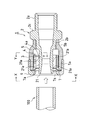
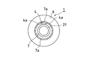
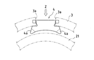
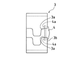
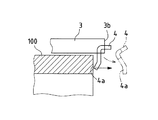
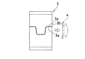
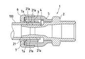
図1は本発明の実施形態の縦断面図である。図2は図1のX−X矢視図、図3は図1のY−Y断面図である。図4は図3のZ矢視図である。 FIG. 1 is a longitudinal sectional view of an embodiment of the present invention. 2 is a view taken along the line XX in FIG. 1, and FIG. 3 is a cross-sectional view taken along the line YY in FIG. 4 is a view taken in the direction of arrow Z in FIG.
この実施形態の管継手1は、例えば架橋ポリエチレンまたはポリブテン等の合成樹脂製の給水・給湯管などの合成樹脂管100の接続に用いる継手であって、継手本体2、圧縮リング3、拡径片4、継手外筒5、袋ナット6、及び抜け止めリング7などによって構成されている。
A
継手本体2は金属(例えば黄銅)の加工品で、合成樹脂管100の内部に挿入されるニップル21が一体形成されている。ニップル21の外周面には、その外周方向に沿って延びる4本の突条(シール用のリブ状突起)21aが形成されている。各突条21aは、断面形状が継手本体2の内方に向けて傾斜する鋸刃形状に加工されている。
The
継手本体2には、接続対象となる部材のソケット等に噛み合う装着用の雄ねじ2aが形成されており、その装着用の雄ねじ2aをソケット等に合わせ、雄ねじ2aの根元部に設けられた六角部2cをスパナやレンチにて回転させることにより接続対象となる部材に管継手1を接続することができる。また、継手本体2には、ニップル21の根元部に継手外筒5を固定するための雄ねじ2bが形成されている。
The
圧縮リング3は、鋼板(ばね鋼)を打ち抜き加工等により展開形状を切り出した後にリング状に賦形した部材で、ニップル21の側方周囲を囲うように配置されている。圧縮リング3の合わせ部は凹凸の嵌め合い構造なっており、その合わせ部の一部分が、後述する拡径片4のはさみ面3aとなっている(図4)。
The
圧縮リング3は、自由な状態(図6参照)での内径が、接続を行う合成樹脂管100の外径よりも所定量だけ小さい寸法となるように設定されており、ニップル21に嵌め込まれた合成樹脂管100の全周を略均等な力にて押圧する(締め付ける)ことができる。
The
拡径片4は、高剛性の鋼板の加工品で、下端部にニップル21の外周方向に沿って延出する一対の脚部4a,4aが一体形成されている。拡径片4は、図1〜図3に示すように、圧縮リング3の先端側端部(管挿入方向の端部)に配置され、圧縮リング3のはさみ面3a,3a間に、圧縮リング3の弾性力に抗して取り付けられる。この取付状態で圧縮リング3の内面とニップル21の外面との間に合成樹脂管100を挿入することが可能な空間が形成されるとともに、その空間内に拡径片4の脚部4aが突出した状態で配置される。
The
継手外筒5は透明(または半透明)の樹脂成形品で、ニップル21及び圧縮リング3の側方を覆う形状に加工されている。継手外筒5の根元部には、継手本体2の雄ねじ2bに噛み合う雌ねじ5bが形成されており、これら雄ねじ2bと雌ねじ5bの噛み合いにより継手外筒5が継手本体2に固定されている。また、継手外筒5の外周面には、先端から中央部にかけて雄ねじ5aが形成されており、この雄ねじ5aに袋ナット(黄銅等の金属製)6がねじ込まれている。
The joint
抜け止めリング7は、ばね鋼の加工品で、合成樹脂管100が挿入される向きに傾斜する複数枚の刃7a・・7aが一体形成されており、その各刃7aの先端が継手本体2に挿入された合成樹脂管100の外周面に引っ掛かることにより、合成樹脂管100の抜けが防止される。抜け止めリング7は袋ナット6によって外方への抜けが阻止される。
The
次に、管接続の手順を説明する。 Next, a procedure for pipe connection will be described.
まず、図1に示すように、接続を行う合成樹脂管100の中心と管継手1のニップル21の中心とを合わせた状態で、合成樹脂管100を継手本体2の内部に挿入して管端部をニップル21に差し込み、次いで合成樹脂管100を更に押し込む。
First, as shown in FIG. 1, with the center of the
この押し込み時において、図5に示すように、合成樹脂管100の先端が継手本体2内の拡径片4の脚部4aに当たった時点で、脚部4aが継手本体2の内方(奥方)に向けて押圧され、拡径片4が圧縮リング3に対して抜け方向に移動される。そして、合成樹脂管100の先端が圧縮リング3の後端面3bよりも前方に位置すると、拡径片4が圧縮リング3から離脱し(図5及び図6)、圧縮リング3が縮径して図6に示す状態となる。
At the time of this pushing, as shown in FIG. 5, when the tip of the
この圧縮リング3の縮径により、合成樹脂管100の管端部が圧縮リング3の弾性力にて締め付けられた状態となるとともに、図7に示すように、ニップル21外周面の突条21aが合成樹脂管100の内面に食い込んでシールが確保される。ここで、圧縮リング3の締め付け力は、ニップル21の突条21aが合成樹脂管100の内面に確実に食い込んで、合成樹脂管100の内周面をニップル21の外周面に密着させることが可能な大きさとする。また、突条21aの高さは、合成樹脂管100の内面への突条21aの食込み量が、例えば合成樹脂管100の肉圧の15〜25%の範囲とすることが好ましい。
Due to the reduced diameter of the
なお、本実施形態において、圧縮リング3から離脱した拡径片4は、ニップル21と継手外筒5との間に形成される空間に残るようになっているので、圧縮リング3の弾性力により拡径片4が勢いよく離脱しても、接続作業者等に当たるおそれがなく接続作業を安全に行うことができる。また、継手外筒5が透明樹脂(または半透明樹脂)にて構成されているので、拡径片4が圧縮リング3から離脱したか否かを目視にて確認することができ、管接続を確実に行うことができる。
In the present embodiment, the diameter-enlarged
以上の実施形態では、ニップル21の外周面に4本のシール用の突条21aを形成しているが、その本数は特に限定されず、接続行う合成樹脂管100のサイズ等によって適宜に選択すればよい。また、突条21aの断面形状は、直角三角形あるいは二等辺三角形等であってもよい。
In the above embodiment, four sealing
本発明は、給水管・給湯管などの各種管の接続に用いられる管継手、特に、架橋ポリエチレンまたはポリブテンなどの樹脂によって成形された合成樹脂管(ホース等)の接続に使用される管継手に有効に利用できる。 The present invention relates to a pipe joint used for connection of various pipes such as a water supply pipe and a hot water supply pipe, and particularly to a pipe joint used for connection of a synthetic resin pipe (such as a hose) formed of a resin such as crosslinked polyethylene or polybutene. It can be used effectively.
1 管継手
2 継手本体
21 ニップル
21a 突条
3 圧縮リング
3a はさみ面
4 拡径片
4a 脚部
5 継手外筒
6 袋ナット
7 抜け止めリング
100 合成樹脂管
DESCRIPTION OF
Claims (1)
It is made of a joint body with an integrally formed nipple inserted into the pipe to be connected, and an elastic material that can be deformed from an expanded state having a diameter larger than that of the nipple to a reduced diameter state in which the end of the tube is fastened to the nipple. A compression ring and a diameter-enlarging piece for holding the compression ring in an expanded state are provided. The diameter of the compression ring is reduced by releasing the diameter-enlarging piece at the tip of the pipe inserted into the nipple when the pipe is connected. In the pipe joint having a structure in which the pipe wall body is pressed against the nipple outer peripheral surface by the elastic force of the seal, the sealing ridge extending along the circumferential direction of the outer peripheral surface is formed on the outer peripheral surface of the nipple. Pipe fittings.
Priority Applications (1)
| Application Number | Priority Date | Filing Date | Title |
|---|---|---|---|
| JP2004109046A JP2005291420A (en) | 2004-04-01 | 2004-04-01 | Pipe fitting |
Applications Claiming Priority (1)
| Application Number | Priority Date | Filing Date | Title |
|---|---|---|---|
| JP2004109046A JP2005291420A (en) | 2004-04-01 | 2004-04-01 | Pipe fitting |
Publications (1)
| Publication Number | Publication Date |
|---|---|
| JP2005291420A true JP2005291420A (en) | 2005-10-20 |
Family
ID=35324570
Family Applications (1)
| Application Number | Title | Priority Date | Filing Date |
|---|---|---|---|
| JP2004109046A Pending JP2005291420A (en) | 2004-04-01 | 2004-04-01 | Pipe fitting |
Country Status (1)
| Country | Link |
|---|---|
| JP (1) | JP2005291420A (en) |
Cited By (5)
| Publication number | Priority date | Publication date | Assignee | Title |
|---|---|---|---|---|
| JP2008025612A (en) * | 2006-07-18 | 2008-02-07 | Sekisui Chem Co Ltd | Resin pipe fittings |
| JP2010043694A (en) * | 2008-08-12 | 2010-02-25 | Nippon Flex Kk | Hose connecting connector |
| JP2012197868A (en) * | 2011-03-22 | 2012-10-18 | Inoue Sudare Kk | Pipe joint |
| CN103429943A (en) * | 2011-03-22 | 2013-12-04 | 井上廉株式会社 | Pipe joint |
| CN113695472A (en) * | 2020-05-20 | 2021-11-26 | 横滨橡胶株式会社 | Method for manufacturing hose joint and method for manufacturing hose assembly |
-
2004
- 2004-04-01 JP JP2004109046A patent/JP2005291420A/en active Pending
Cited By (6)
| Publication number | Priority date | Publication date | Assignee | Title |
|---|---|---|---|---|
| JP2008025612A (en) * | 2006-07-18 | 2008-02-07 | Sekisui Chem Co Ltd | Resin pipe fittings |
| JP2010043694A (en) * | 2008-08-12 | 2010-02-25 | Nippon Flex Kk | Hose connecting connector |
| JP2012197868A (en) * | 2011-03-22 | 2012-10-18 | Inoue Sudare Kk | Pipe joint |
| CN103429943A (en) * | 2011-03-22 | 2013-12-04 | 井上廉株式会社 | Pipe joint |
| CN103429943B (en) * | 2011-03-22 | 2015-06-17 | 井上廉株式会社 | Pipe joint |
| CN113695472A (en) * | 2020-05-20 | 2021-11-26 | 横滨橡胶株式会社 | Method for manufacturing hose joint and method for manufacturing hose assembly |
Similar Documents
| Publication | Publication Date | Title |
|---|---|---|
| JP5091191B2 (en) | Pipe fitting | |
| JP2008291886A (en) | Pipe joint | |
| JP2008286259A (en) | Pipe joint | |
| JP2005291420A (en) | Pipe fitting | |
| JP2002357295A (en) | Pipe fittings | |
| JP2010127409A (en) | Tube fitting | |
| JP2005291418A (en) | Pipe fitting | |
| JP2002364797A (en) | Pipe fittings | |
| KR200447122Y1 (en) | Hose connector for sprinkler | |
| JP2005291419A (en) | Pipe fitting | |
| JP4564427B2 (en) | Connection structure between metal pipe and pipe joint | |
| KR200439127Y1 (en) | Fastening Crimp Holders for Pipe Joints | |
| JP4206391B2 (en) | Pipe joint structure | |
| JP2006029355A (en) | Pipe joint | |
| JP2004527704A (en) | Pipe fittings including body and nut | |
| JP4935444B2 (en) | Bite type fittings, refrigeration equipment and hot water equipment | |
| JP4424809B2 (en) | Pipe joint for synthetic resin pipe | |
| JP2015105695A (en) | Joint for flexible pipe | |
| JP3115847U (en) | Resin pipe joint | |
| JP4620411B2 (en) | Piping connection fitting | |
| JP2000074280A (en) | Separation prevention fitting for soft pipe | |
| JP2007232121A (en) | Pipe fitting | |
| KR200302725Y1 (en) | Hose coupler for spring cooler | |
| JP2008082373A (en) | Bite type fittings, refrigeration equipment and hot water equipment | |
| JP3158459U (en) | Hand-tightened joint |
Legal Events
| Date | Code | Title | Description |
|---|---|---|---|
| A621 | Written request for application examination |
Free format text: JAPANESE INTERMEDIATE CODE: A621 Effective date: 20070202 |
|
| A977 | Report on retrieval |
Effective date: 20090820 Free format text: JAPANESE INTERMEDIATE CODE: A971007 |
|
| A131 | Notification of reasons for refusal |
Free format text: JAPANESE INTERMEDIATE CODE: A131 Effective date: 20090825 |
|
| A521 | Written amendment |
Effective date: 20091021 Free format text: JAPANESE INTERMEDIATE CODE: A523 |
|
| A02 | Decision of refusal |
Effective date: 20091208 Free format text: JAPANESE INTERMEDIATE CODE: A02 |