JP2012206824A - Internal residual stress calculating device, and program - Google Patents

Internal residual stress calculating device, and program Download PDF

Info

Publication number
JP2012206824A
JP2012206824A JP2011073411A JP2011073411A JP2012206824A JP 2012206824 A JP2012206824 A JP 2012206824A JP 2011073411 A JP2011073411 A JP 2011073411A JP 2011073411 A JP2011073411 A JP 2011073411A JP 2012206824 A JP2012206824 A JP 2012206824A
Authority
JP
Japan
Prior art keywords
medium
residual stress
deformation
internal residual
correction
Prior art date
Legal status (The legal status is an assumption and is not a legal conclusion. Google has not performed a legal analysis and makes no representation as to the accuracy of the status listed.)
Withdrawn
Application number
JP2011073411A
Other languages
Japanese (ja)
Inventor
Ryosuke Takahashi
良輔 高橋
Tomoyuki Ito
朋之 伊藤
Kiyoshi Hosoi
清 細井
Takashi Ogino
孝 荻野
Current Assignee (The listed assignees may be inaccurate. Google has not performed a legal analysis and makes no representation or warranty as to the accuracy of the list.)
Fujifilm Business Innovation Corp
Original Assignee
Fuji Xerox Co Ltd
Priority date (The priority date is an assumption and is not a legal conclusion. Google has not performed a legal analysis and makes no representation as to the accuracy of the date listed.)
Filing date
Publication date
Application filed by Fuji Xerox Co Ltd filed Critical Fuji Xerox Co Ltd
Priority to JP2011073411A priority Critical patent/JP2012206824A/en
Priority to US13/214,850 priority patent/US9037420B2/en
Publication of JP2012206824A publication Critical patent/JP2012206824A/en
Withdrawn legal-status Critical Current

Links

Images

Classifications

    • GPHYSICS
    • G01MEASURING; TESTING
    • G01LMEASURING FORCE, STRESS, TORQUE, WORK, MECHANICAL POWER, MECHANICAL EFFICIENCY, OR FLUID PRESSURE
    • G01L5/00Apparatus for, or methods of, measuring force, work, mechanical power, or torque, specially adapted for specific purposes
    • G01L5/0047Apparatus for, or methods of, measuring force, work, mechanical power, or torque, specially adapted for specific purposes measuring forces due to residual stresses

Abstract

PROBLEM TO BE SOLVED: To calculate an estimation value of an internal residual stress of a medium by paying attention to deformation of residues after the medium passes through a correcting device.SOLUTION: In the correcting device where the medium receiving image formation corrects deformation, an internal residual stress calculating device estimates a temporal variation of received deformation and calculates the internal residual stress of the medium after passing through the correcting device on the basis of a relational expression including an elasticity term and a term related to a plastic deformation and the temporal variation in deformation estimated by an estimation unit.

Description

本発明は、内部残留応力算出装置及びプログラムに関する。   The present invention relates to an internal residual stress calculation device and a program.

記録媒体についての曲率履歴情報を得る曲率履歴取得手段と、記録媒体についての粘弾性履歴情報を得る粘弾性履歴取得手段と、曲率履歴情報と粘弾性履歴情報とに基づき、記録媒体の曲率変化に応じて増減する当該記録媒体の内部応力を積算して、当該曲率変化を経た後における当該記録媒体の内部応力分布を得る内部応力分布算出手段と、内部応力分布算出手段が得た内部応力分布と釣り合う記録媒体の変形曲率を、曲率変化を経た後の記録媒体における変形曲率として算出する変形曲率算出手段とを備えた変形曲率予測装置が特許文献1に開示されている。   Based on the curvature history acquisition means for obtaining the curvature history information about the recording medium, the viscoelastic history acquisition means for obtaining the viscoelastic history information about the recording medium, and the curvature history information and the viscoelastic history information, The internal stress distribution calculating means that obtains the internal stress distribution of the recording medium after accumulating the internal stress of the recording medium that increases or decreases according to the curvature change, and the internal stress distribution obtained by the internal stress distribution calculating means Patent Document 1 discloses a deformed curvature predicting device including deformed curvature calculating means for calculating a deformed curvature of a balanced recording medium as a deformed curvature in a recording medium after undergoing a curvature change.

特開2009−046230号公報JP 2009-046230 A

媒体が矯正装置を通過した後に残留する変形に配慮した、媒体の内部残留応力の予測値を算出すること。   Calculate the predicted value of the internal residual stress of the medium, taking into account the deformation remaining after the medium passes through the straightening device.

請求項1記載の発明は、内部残留応力算出装置であって、画像の形成を受ける媒体が、変形を矯正する矯正装置において受ける変形量の時間変化を推定する推定手段と、弾性項と、塑性変形に関する項と、を含んだ関係式、及び前記推定手段で推定された変形量の時間変化を用いて、前記矯正装置を通過した後の前記媒体の内部残留応力を算出する算出手段と、を含むこととしたものである。   The invention according to claim 1 is an internal residual stress calculation device, wherein the medium on which image formation is performed estimates the time variation of the deformation amount received by the correction device for correcting the deformation, the elastic term, and the plasticity A calculation means for calculating an internal residual stress of the medium after passing through the correction device, using a relational expression including a deformation, and a temporal change of the deformation amount estimated by the estimation means. It is meant to be included.

請求項2記載の発明は、請求項1記載の内部残留応力算出装置であって、前記算出手段が用いる関係式は、弾性係数をK、粘性係数をμ、降伏応力をσY、点iでの時刻nにおける応力をσi nとして、

Figure 2012206824
Figure 2012206824
Figure 2012206824
のうちから、媒体の種類に応じて選択されることとしたものである。 The invention according to claim 2 is the internal residual stress calculation device according to claim 1, wherein the relational expression used by the calculation means is an elastic coefficient K, a viscosity coefficient μ, a yield stress σY, and a point i. The stress at time n is σ i n ,
Figure 2012206824
Figure 2012206824
Figure 2012206824
Of these, it is selected according to the type of medium.

請求項3記載の発明は、請求項1または2記載の内部残留応力算出装置であって、前記媒体が、矯正装置において受ける変形量の時間変化を表す情報を予め保持する保持手段をさらに含み、前記推定手段は、前記保持手段が保持する情報に基づいて、前記媒体が矯正装置において受ける変形量の時間変化を推定することとしたものである。   Invention of Claim 3 is an internal residual stress calculation apparatus of Claim 1 or 2, Comprising: The said medium further contains the holding means to hold | maintain the information showing the time change of the deformation amount which a medium receives in a correction apparatus beforehand, The estimation means estimates a time change of a deformation amount that the medium receives in the correction device based on information held by the holding means.

請求項4記載の発明は、プログラムであって、コンピュータを、画像の形成を受ける媒体が、変形を矯正する矯正装置において受ける変形量の時間変化を推定する推定手段と、弾性項と、塑性変形に関する項と、を含んだ関係式、及び前記推定手段で推定された変形量の時間変化を用いて、前記矯正装置を通過した後の前記媒体の内部残留応力を算出する算出手段と、として機能させることとしたものである。   The invention according to claim 4 is a program, wherein the computer is configured to estimate a change over time of the amount of deformation that the medium that receives the image formation receives in a correction device that corrects the deformation, an elastic term, and a plastic deformation And a calculation means for calculating an internal residual stress of the medium after passing through the correction device, using a relational expression including: and a time variation of the deformation amount estimated by the estimation means It is intended to let you.

請求項1,4記載の発明によると、媒体が矯正装置を通過した後に残留する塑性変形に配慮した、媒体の内部残留応力の予測値を算出できる。   According to the first and fourth aspects of the invention, the predicted value of the internal residual stress of the medium can be calculated in consideration of the plastic deformation remaining after the medium passes through the correction device.

請求項2記載の発明によると、媒体の種類に応じた塑性変形に配慮した予測値が算出できる。   According to the invention described in claim 2, it is possible to calculate a predicted value in consideration of plastic deformation according to the type of medium.

請求項3記載の発明によると、予め保持している算出に必要な変形量の時間変化を利用して演算できる。   According to the third aspect of the present invention, the calculation can be performed using the temporal change of the deformation amount necessary for the calculation that is held in advance.

本発明の実施の形態に係る内部残留応力算出装置を含んだ画像形成装置の例を表す構成ブロック図である。1 is a configuration block diagram illustrating an example of an image forming apparatus including an internal residual stress calculation device according to an embodiment of the present invention. 矯正装置の例を表す説明図である。It is explanatory drawing showing the example of a correction apparatus. 矯正装置における変形履歴の一例を表す説明図である。It is explanatory drawing showing an example of the deformation | transformation log | history in a correction apparatus. 矯正装置における変形履歴の別の例を表す説明図である。It is explanatory drawing showing another example of the deformation | transformation log | history in a correction apparatus. 本発明の実施の形態に係る内部残留応力算出装置の例を表す機能ブロック図である。It is a functional block diagram showing the example of the internal residual stress calculation apparatus which concerns on embodiment of this invention. 本発明の実施の形態に係る内部残留応力算出装置が利用するルック・アップ・テーブルの例を表す説明図である。It is explanatory drawing showing the example of the look-up table which the internal residual stress calculation apparatus which concerns on embodiment of this invention utilizes. 本発明の実施の形態に係る内部残留応力算出装置により演算される媒体内部の点の設定例を表す説明図である。It is explanatory drawing showing the example of a setting of the point inside the medium calculated by the internal residual stress calculation apparatus which concerns on embodiment of this invention. 本発明の実施の形態に係る内部残留応力算出装置により演算される残留応力の例を表す説明図である。It is explanatory drawing showing the example of the residual stress calculated by the internal residual stress calculation apparatus which concerns on embodiment of this invention. 本発明の実施の形態に係る内部残留応力算出装置の動作例を表すフローチャート図である。It is a flowchart figure showing the example of operation of the internal residual stress calculation device concerning an embodiment of the invention. 本発明の実施の形態に係る内部残留応力算出装置の動作例を表す説明図である。It is explanatory drawing showing the operation example of the internal residual stress calculation apparatus which concerns on embodiment of this invention.

本発明の実施の形態について図面を参照しながら説明する。本実施の形態の内部残留応力算出装置1は、例えば、いわゆるデカーラ(媒体の変形を矯正する矯正装置)を備えた画像形成装置において利用される。本実施の形態の内部残留応力算出装置1を含んだ画像形成装置は、図1に例示するように、この内部残留応力算出装置1のほか、画像形成を受ける媒体(例えば用紙等、シート状のものであるとする)を保持する媒体保持部2、この媒体保持部2から媒体を搬送する搬送部3、外部から入力される画像情報に基づいて、搬送部3により搬送された媒体上に画像を形成する画像形成部4、及び、搬送部3上に設けられ、当該搬送部3により搬送される画像形成後の媒体の変形を矯正する矯正部5、これら全体を制御する機器制御部6を含む。   Embodiments of the present invention will be described with reference to the drawings. The internal residual stress calculation device 1 according to the present embodiment is used in, for example, an image forming apparatus including a so-called decurler (correction device that corrects deformation of a medium). As shown in FIG. 1, the image forming apparatus including the internal residual stress calculating apparatus 1 according to the present embodiment is not only the internal residual stress calculating apparatus 1 but also a medium (for example, paper or the like, sheet-like) that receives image formation. An image on the medium conveyed by the conveying unit 3 based on the image information inputted from the outside, the medium holding unit 2 holding the medium holding unit 2, the conveying unit 3 conveying the medium from the medium holding unit 2 An image forming unit 4 that forms the image, a correction unit 5 that is provided on the conveyance unit 3 and corrects deformation of the medium after image formation conveyed by the conveyance unit 3, and a device control unit 6 that controls the whole. Including.

ここで機器制御部6は、画像形成装置の外部から画像形成の指示を受けて、搬送部3を制御して、媒体保持部2に保持された媒体を画像形成部4まで搬送させる。そして機器制御部6は、画像形成部4にて、指示に係る画像をこの媒体上に形成させる。そして矯正部5が画像が形成された媒体の変形を矯正する。また機器制御部6は、媒体保持部2に保持され、画像形成先となる媒体の剛性を特定する情報を出力する。この情報は、予め利用者等から与えられたものとしてもよい。   Here, the device control unit 6 receives an instruction for image formation from the outside of the image forming apparatus, controls the transport unit 3, and transports the medium held in the medium holding unit 2 to the image forming unit 4. The device control unit 6 causes the image forming unit 4 to form an image according to the instruction on the medium. The correction unit 5 corrects the deformation of the medium on which the image is formed. The device control unit 6 outputs information that is held by the medium holding unit 2 and that specifies the rigidity of the medium that is the image forming destination. This information may be given in advance by a user or the like.

本実施の形態の内部残留応力算出装置1は、制御部11と、記憶部12と、入力部13と、出力部14とを含んで構成される。
ここで制御部11は、CPU(Central Processing Unit)等のプログラム制御デバイスを含んで構成される。この制御部11は、記憶部12に格納されたプログラムに従って動作する。具体的にこの制御部11は、画像の形成を受ける媒体が、変形を矯正する矯正装置としての矯正部5において受ける変形量の時間変化を推定する。制御部11は、さらに、弾性項と、塑性変形に関する項と、を含んだ関係式、及び推定された変形量の時間変化を用いて、矯正部5を通過した後の媒体の内部残留応力の予測値を算出する処理を実行する。この制御部11が実行する処理の内容については、後に詳しく述べる。
The internal residual stress calculation device 1 according to the present embodiment includes a control unit 11, a storage unit 12, an input unit 13, and an output unit 14.
Here, the control unit 11 includes a program control device such as a CPU (Central Processing Unit). The control unit 11 operates according to a program stored in the storage unit 12. Specifically, the control unit 11 estimates a temporal change in the amount of deformation that the medium that receives the image formation receives in the correction unit 5 as a correction device that corrects the deformation. The control unit 11 further uses a relational expression including an elastic term and a term relating to plastic deformation, and a temporal change in the estimated deformation amount to determine the internal residual stress of the medium after passing through the correction unit 5. A process for calculating a predicted value is executed. The contents of the processing executed by the control unit 11 will be described in detail later.

記憶部12は、メモリデバイス等であり、制御部11が実行するプログラムを保持する。このプログラムは、DVD−ROM(Digital Versatile Disc Read Only Memory)等のコンピュータ可読な記録媒体に格納されて提供され、この記憶部12に複写等されたものであってもよい。また、この記憶部12は、制御部11のワークメモリとしても動作する。   The storage unit 12 is a memory device or the like, and holds a program executed by the control unit 11. This program may be provided by being stored in a computer-readable recording medium such as a DVD-ROM (Digital Versatile Disc Read Only Memory) and copied to the storage unit 12. The storage unit 12 also operates as a work memory for the control unit 11.

入力部13は、画像形成に使用される媒体の種類を表す情報の入力を、機器制御部6から受けて制御部11に出力する。出力部14は、制御部11から入力される情報や指示を、矯正部5に出力する。   The input unit 13 receives input of information indicating the type of medium used for image formation from the device control unit 6 and outputs the information to the control unit 11. The output unit 14 outputs information and instructions input from the control unit 11 to the correction unit 5.

矯正部5は、具体的には図2に例示するように、互いに押圧力を加え合う一対のローラ21a,bを少なくとも一対、含んで構成される。矯正部5では、このローラ21a,bの間に媒体に圧力を加えることで、媒体に強制的に変形を加える。この矯正部5においては、例えばローラ21a,bの軸間距離を変化させることで押圧力を変化させることができるようになっている。こうしたデカーラとしての矯正部5は、広く知られているのでここでの詳しい説明を省略する。   Specifically, as illustrated in FIG. 2, the correction unit 5 includes at least a pair of rollers 21 a and 21 b that apply a pressing force to each other. In the correction unit 5, the medium is forcibly deformed by applying pressure to the medium between the rollers 21a and 21b. In the correction unit 5, for example, the pressing force can be changed by changing the distance between the axes of the rollers 21a and 21b. Since such a decurler correction unit 5 is widely known, detailed description thereof is omitted here.

この矯正部5は、以上の構成を備えるので、この矯正部5を通過する媒体には、媒体の厚さ方向に、時間的に図3に例示するような変形が加えられる。図3において横軸は経過時間、縦軸は用紙の変形量(当初の状態から媒体が受ける厚さ方向の変位量)を表す。図3では媒体の剛性に応じて複数のグラフが描かれており、時刻t1を経過した時点でローラ21a,bによって大きく変形を受け(X)、ローラ21a,bから排出された直後(時刻t2)は媒体面の一方側に変形させられた状態となるが、時間が経過するにつれて、他方側へ変形量が変化する状態が示されている。また、別の矯正部5では、3対のローラを備え、それぞれのローラ対によって図4に例示するように、3度の変形(X,Y,Z)が逐次的に行われる。   Since the correction unit 5 has the above-described configuration, the medium passing through the correction unit 5 is temporally deformed as illustrated in FIG. 3 in the thickness direction of the medium. In FIG. 3, the horizontal axis represents the elapsed time, and the vertical axis represents the deformation amount of the paper (the displacement amount in the thickness direction that the medium receives from the initial state). In FIG. 3, a plurality of graphs are drawn according to the rigidity of the medium, and when time t1 has elapsed, the roller 21a, b is greatly deformed (X) and immediately after being discharged from the roller 21a, b (time t2). ) Is in a state of being deformed to one side of the medium surface, but a state in which the amount of deformation changes to the other side as time passes is shown. In addition, another correction unit 5 includes three pairs of rollers, and three degrees of deformation (X, Y, Z) are sequentially performed by each roller pair as illustrated in FIG.

次に、内部残留応力算出装置1の制御部11における、媒体に生じる変形を予測する処理について述べる。制御部11は機能的には、図5に例示するように、推定部31と、算出部32と、矯正量算出部33とを含んで構成される。   Next, a process for predicting the deformation occurring in the medium in the control unit 11 of the internal residual stress calculating apparatus 1 will be described. The control unit 11 is functionally configured to include an estimation unit 31, a calculation unit 32, and a correction amount calculation unit 33, as illustrated in FIG.

推定部31は、媒体の剛性に応じて、媒体が矯正部5において受ける変形量の時間変化(曲率履歴)を推定する。この推定は、図3,4に例示したグラフに対応する数式、または複数の時刻におけるグラフ上の点の座標(時刻,変形量)をリスト(一覧)にしたデータを求めることで行われる。本実施の形態の一例では、矯正部5により矯正が行われる前のある時点t=0から、矯正が行われた後の時点t=Tまでを予め定めた間隔dtで分割して得た各時刻t0,t1,t2…,tn(ただしt0=0、ti-1<ti,ti+1−ti=dt,tn=T)における変形量の値d0,d1,…dnを、図6に例示するように表(ルック・アップ・テーブル、以下、LUT(Look-Up Table)と呼ぶ)として記憶部12に保持しておく。このLUTは、媒体の剛性ごとに作成され、記憶部12に格納されていてもよい。この場合、機器制御部6が出力する情報で特定される媒体の剛性に対応した表が読み出される。   The estimation unit 31 estimates a temporal change (curvature history) of the deformation amount that the medium undergoes in the correction unit 5 according to the rigidity of the medium. This estimation is performed by obtaining a mathematical expression corresponding to the graphs illustrated in FIGS. 3 and 4 or data in which the coordinates (time, deformation amount) of points on the graph at a plurality of times are listed. In an example of the present embodiment, each time point obtained by dividing a predetermined time interval dt from a time point t = 0 before correction is performed by the correction unit 5 to a time point t = T after correction is performed. FIG. 6 shows deformation values d0, d1,... Dn at times t0, t1, t2..., Tn (where t0 = 0, ti-1 <ti, ti + 1-ti = dt, tn = T). As described above, the data is stored in the storage unit 12 as a table (look-up table, hereinafter referred to as LUT (Look-Up Table)). This LUT may be created for each medium stiffness and stored in the storage unit 12. In this case, a table corresponding to the stiffness of the medium specified by the information output by the device control unit 6 is read out.

また、本実施形態の別の例では、図3,4に例示したグラフに対応する近似式ないし理論式が予め定められ、この近似式や理論式に基づいて、推定部31が、矯正部5により矯正が行われる前のある時点t=0から、矯正が行われた後の時点t=Tまでを予め定めた間隔dtで分割して得た各時刻t0,t1,t2…,tn(ただしt0=0、ti-1<ti,ti+1−ti=dt,tn=T)における変形量の値d0,d1,…dnを演算する。   In another example of the present embodiment, an approximate expression or a theoretical expression corresponding to the graphs illustrated in FIGS. 3 and 4 is determined in advance. Based on the approximate expression or the theoretical expression, the estimation unit 31 can correct the correction unit 5. .., Tn (provided that each time t0, t1, t2,..., Tn obtained by dividing an interval from a certain time t = 0 before correction is performed to a time t = T after correction is performed at a predetermined interval dt) The deformation values d0, d1,... dn at t0 = 0, ti-1 <ti, ti + 1-ti = dt, tn = T) are calculated.

この場合も、近似式等には媒体の剛性に対応するパラメータが含まれ、機器制御部6が出力する情報で特定される媒体の剛性に対応した値が演算されてもよいし、媒体の剛性ごとに異なる近似式等がそれぞれ定められ、機器制御部6が出力する情報で特定される剛性に対応した近似式等が用いられて、各値が演算されてもよい。ここで近似式や理論式は、例えば構造解析の技術を用いて作成すればよい。   Also in this case, the approximate expression or the like includes a parameter corresponding to the medium rigidity, and a value corresponding to the medium rigidity specified by the information output from the device control unit 6 may be calculated. Different approximation formulas or the like may be determined for each, and each value may be calculated using an approximation formula or the like corresponding to the rigidity specified by the information output from the device control unit 6. Here, the approximate expression and the theoretical expression may be created using, for example, a structure analysis technique.

さらに、また別の例では、推定部31は、機器制御部6が出力する情報で特定される媒体の剛性に対応したLUTが記憶部12に格納されているか否かを調べ、格納されていれば、当該LUTを参照して矯正部5により矯正が行われる前のある時点t=0から、矯正が行われた後の時点t=Tまでを予め定めた間隔dtで分割して得た各時刻t0,t1,t2…,tn(ただしt0=0、ti-1<ti,ti+1−ti=dt,tn=T)における変形量の値d0,d1,…dnを取得し、格納されていなければ、構造解析の知識によって作成された近似式等を用いて、各時刻t0,t1,t2…,tn(ただしt0=0、ti-1<ti,ti+1−ti=dt,tn=T)における変形量の値d0,d1,…dnを演算することとしてもよい。   In yet another example, the estimation unit 31 checks whether or not an LUT corresponding to the stiffness of the medium specified by the information output from the device control unit 6 is stored in the storage unit 12. For example, with reference to the LUT, each time obtained by dividing from a certain time t = 0 before correction by the correction unit 5 to a time t = T after correction is performed at a predetermined interval dt. .., Tn (where t0 = 0, ti-1 <ti, ti + 1-ti = dt, tn = T) are obtained and stored as deformation values d0, d1,... Dn at times t0, t1, t2,. If not, each time t0, t1, t2,..., Tn (however, t0 = 0, ti-1 <ti, ti + 1-ti = dt, tn) using an approximation formula created by knowledge of structural analysis. = T), the deformation amount values d0, d1,... Dn may be calculated.

算出部32は、推定部31が演算した結果を利用して、矯正部5を通過した後の媒体の内部残留応力を算出する。具体的にこの算出部32は、まず、推定部31が求めた曲率履歴の情報から、媒体の内部の各点における歪みεの時間変化を算出する。   The calculation unit 32 calculates the internal residual stress of the medium after passing through the correction unit 5 using the result calculated by the estimation unit 31. Specifically, the calculation unit 32 first calculates the temporal change of the strain ε at each point inside the medium from the curvature history information obtained by the estimation unit 31.

具体的に算出部32は、図7に示すように、媒体の搬送方向に予め定めた位置X(媒体の搬送方向中央など)での仮想の切断面において、厚さ方向にN個の点p1,p2,…,pNをとり、これら各点における歪みεの時間変化(εi(t)、ただしi=1,2,…N)を得る。ここでは、予め定めた時間間隔Δtを用い、このΔtごとの各点の歪みεの時間変化を、予め定めた時間範囲(例えばt=TsからTe)で得ておくものとする。ここで時間範囲の末尾は、媒体上で演算に係る位置Xに対応する部分が、矯正部5を通過した後の時刻とする。   Specifically, as shown in FIG. 7, the calculation unit 32 has N points p1 in the thickness direction on a virtual cut surface at a position X predetermined in the medium transport direction (such as the center of the medium transport direction). , p2,..., pN, and obtain the time change (εi (t) where i = 1, 2,... N) of the strain ε at each point. Here, it is assumed that a predetermined time interval Δt is used, and a time change of the strain ε at each point for each Δt is obtained in a predetermined time range (for example, t = Ts to Te). Here, the end of the time range is the time after the portion corresponding to the position X related to the calculation on the medium passes through the correction unit 5.

またここで変形履歴の時間範囲(t=0からT)や時間間隔dtが、ここで算出される応力の時間変化の算出範囲や時間差分Δtと異なっている場合は、変形履歴の情報を内挿または外挿してΔε/Δtを得ることとすればよい。なお、本来であれば、図7に例示した媒体内部の点は、厚さ方向のみならず、媒体の搬送方向に垂直な方向にも複数設定し、二次元的に考えるべきものであるが、ここでは矯正部5が媒体の搬送方向に垂直な方向には均一に変形を与えるものと考えて一次元的にしている。二次元的に演算を行う場合も、一次元的に行った演算を媒体搬送方向に垂直な方向に設定した点の数だけ繰り返して行えばよい(さらに媒体の搬送方向にも複数の点を設定し、媒体を三次元的にモデル化して演算を行う場合も同様に、各点の数だけ繰り返してここで説明する演算を行えばよい)ので、ここでは一次元的に算出を行う場合を例として述べることとする。   If the deformation history time range (from t = 0 to T) or the time interval dt is different from the stress time change calculation range or the time difference Δt calculated here, the deformation history information is included. It is only necessary to obtain Δε / Δt by insertion or extrapolation. Note that, originally, a plurality of points inside the medium illustrated in FIG. 7 should be considered not only in the thickness direction but also in a direction perpendicular to the conveyance direction of the medium, and considered two-dimensionally. Here, the correction unit 5 is assumed to be uniformly deformed in a direction perpendicular to the medium conveyance direction, and is made one-dimensional. When performing a two-dimensional calculation, it is sufficient to repeat the one-dimensional calculation as many times as the number of points set in the direction perpendicular to the medium transport direction (and set a plurality of points in the medium transport direction as well). Similarly, when the calculation is performed by modeling the medium three-dimensionally, it is only necessary to repeat the calculation described here by the number of points). Will be described as follows.

そして算出部32は、応力とひずみの関係を表す

Figure 2012206824
の式を用いて内部残留応力の予測値を算出する。ここでKは弾性係数、μは粘性係数、σYは降伏応力を表す。粘性係数μは、初期粘性係数μ0と、歪み依存係数Aと、粘性要素ひずみεvisとを用いて、
Figure 2012206824
と表すことができる。また、弾性係数Kと降伏応力σYとは、いずれも対象となる媒体に固有な情報として予め定めておく。 The calculation unit 32 represents the relationship between stress and strain.
Figure 2012206824
The predicted value of internal residual stress is calculated using the following formula. Here, K is an elastic coefficient, μ is a viscosity coefficient, and σY is a yield stress. The viscosity coefficient μ is obtained by using the initial viscosity coefficient μ0, the strain dependence coefficient A, and the viscous element strain εvis.
Figure 2012206824
It can be expressed as. The elastic coefficient K and the yield stress σY are both determined in advance as information unique to the target medium.

またこの(1)式において、

Figure 2012206824
が弾性を表す弾性項、
Figure 2012206824
が塑性変形に関する項となる。 In this equation (1),
Figure 2012206824
Is an elastic term representing elasticity,
Figure 2012206824
Is a term related to plastic deformation.

算出部32は、図7に示すように、媒体の搬送方向に予め定めた位置(媒体の搬送方向中央など)での仮想の切断面において、厚さ方向にN個の点p1,p2,…,pNをとり、これら各点での時刻nにおける応力を

Figure 2012206824
とする。図7において媒体が延びている図中上側の面での歪みを延び歪み(ε>0)とし、媒体が縮んでいる図中下側の面での歪みを縮み歪み(ε<0)とする。歪みがない状態がε=0の状態である。(1)式を応力に関する時間差分(間隔Δt)の形に変形して、これら各点での応力の前進差分を表す式、
Figure 2012206824
が得られる。本実施の形態の算出部32は、(1)式に基づく(8)式を利用して矯正部5を通過した後の媒体の内部残留応力の予測値を算出する。(8)式においては、
Figure 2012206824
が弾性を表す弾性項、
Figure 2012206824
が塑性変形に関する項となる。 As shown in FIG. 7, the calculation unit 32 has N points p1, p2,... In the thickness direction on a virtual cut surface at a predetermined position in the medium conveyance direction (such as the center in the medium conveyance direction). , PN and the stress at time n at each of these points
Figure 2012206824
And In FIG. 7, the strain on the upper surface in the drawing in which the medium extends is defined as strain (ε> 0), and the strain on the lower surface in the diagram in which the medium is contracted is referred to as contraction strain (ε <0). . A state where there is no distortion is a state where ε = 0. Equation (1) is transformed into a time difference (interval Δt) related to stress, and an equation representing the forward difference of stress at each of these points,
Figure 2012206824
Is obtained. The calculation part 32 of this Embodiment calculates the predicted value of the internal residual stress of the medium after passing the correction | amendment part 5 using (8) Formula based on (1) Formula. In equation (8):
Figure 2012206824
Is an elastic term representing elasticity,
Figure 2012206824
Is a term related to plastic deformation.

なお、τは時定数であり、

Figure 2012206824
であり、またεYは、降伏限界ひずみを表し、
Figure 2012206824
である。 Note that τ is a time constant,
Figure 2012206824
And εY represents the yield limit strain,
Figure 2012206824
It is.

算出部32は、先に演算した歪みεの時間変化、すなわちΔε/Δtを、この(8)式に代入して、応力を逐次的に演算し、図7に示した各点での時刻t=Teでの応力(この時点では矯正部5を通過しているので、内部に残留している応力)の値を得る。つまり、この演算により算出部32は、媒体の搬送方向の一点Xにおいて、厚さ方向にN個の点p1,p2,…,pNをとったときの、これら各点での時刻t=Teにおける各内部残留応力の値を得て、これらの値を内部残留応力の予測値を表す情報として出力する。   The calculation unit 32 substitutes the time change of the strain ε calculated earlier, that is, Δε / Δt, into the equation (8) to calculate the stress sequentially, and the time t at each point shown in FIG. = The value of stress at Te (the stress remaining inside because it passes through the correction portion 5 at this time) is obtained. That is, by this calculation, the calculation unit 32 takes the N points p1, p2,..., PN in the thickness direction at one point X in the conveyance direction of the medium at the time t = Te at these points. Each internal residual stress value is obtained, and these values are output as information representing the predicted value of the internal residual stress.

矯正量算出部33は、算出部32が算出した内部残留応力の予測値の情報を用いて、矯正部5を通過した媒体の内部残留応力が少なくなるような矯正量の情報を算出する。具体的には、厚さ方向の各点での内部残留応力の予測値に対し、釣り合いモーメントが「0」となるような応力を算出する(図8(a))。そして矯正量算出部33は、当該算出した内部残留応力の予測値の分布に応じて矯正部5のローラの軸間距離等、矯正量を制御する情報を生成して出力する。このような応力の分布情報に応じた矯正量を制御する情報の生成については広く知られた方法を採用できるので、ここでの詳しい説明を省略する。   The correction amount calculation unit 33 uses the information on the predicted value of the internal residual stress calculated by the calculation unit 32 to calculate information on the correction amount that reduces the internal residual stress of the medium that has passed through the correction unit 5. Specifically, the stress is calculated so that the balance moment becomes “0” with respect to the predicted value of the internal residual stress at each point in the thickness direction (FIG. 8A). Then, the correction amount calculation unit 33 generates and outputs information for controlling the correction amount, such as the distance between the rollers of the correction unit 5 according to the calculated distribution of the predicted value of the internal residual stress. A widely known method can be adopted for generating information for controlling the correction amount in accordance with such stress distribution information, and a detailed description thereof will be omitted here.

また本実施の形態において、媒体には予め変形が生じていることがある(初期変形と呼ぶ)。この場合、制御部11の算出部32は、当該初期変形に応じて、図7の各点での内部応力(初期内部応力)を算出しておき、(8)式で算出した対応する点での内部残留応力の予測値に加算して、内部残留応力の予測値を補正し、新たな内部残留応力の予測値として出力することとしてもよい。この場合、矯正量算出部33は、補正された厚さ方向の各点での内部残留応力の予測値に対し、釣り合いモーメントが「0」となるような応力を算出する(図8(b))。なお、初期変形は、予め搬送部3上に設けられた、変形量を検出する装置(不図示)によって検出する。制御部11は、当該装置が検出した変形量の情報を受け、当該情報を用いて初期内部応力を算出する。   In the present embodiment, the medium may be deformed in advance (referred to as initial deformation). In this case, the calculation unit 32 of the control unit 11 calculates the internal stress (initial internal stress) at each point in FIG. 7 according to the initial deformation, and at the corresponding point calculated by the equation (8). The predicted value of the internal residual stress may be added to the predicted value of the internal residual stress, and the predicted value of the internal residual stress may be corrected and output as a new predicted value of the internal residual stress. In this case, the correction amount calculation unit 33 calculates a stress such that the balance moment becomes “0” with respect to the predicted value of the internal residual stress at each corrected point in the thickness direction (FIG. 8B). ). The initial deformation is detected by a device (not shown) for detecting the deformation amount provided in advance on the transport unit 3. The control unit 11 receives information on the deformation amount detected by the device, and calculates the initial internal stress using the information.

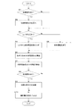
本実施の形態の内部残留応力算出装置1は以上の構成を備えており、次に例示するように動作する。すなわち、内部残留応力算出装置1は、図9に例示するように、機器制御部6が出力する媒体の剛性を特定する情報を受け入れておく。そしてまず初期変形があるか否かを判断する(S1)。この判断は、例えば初期変形の変形量を検出する装置から変形量の情報が入力され、かつ、入力された変形量が「0」でないときに初期変形があると判断し、そうでない場合は初期変形がないものと判断することで行う。   The internal residual stress calculation device 1 of the present embodiment has the above-described configuration and operates as exemplified below. That is, the internal residual stress calculation apparatus 1 accepts information for specifying the rigidity of the medium output by the device control unit 6, as illustrated in FIG. First, it is determined whether or not there is an initial deformation (S1). This determination is made, for example, when the deformation amount information is input from a device that detects the deformation amount of the initial deformation and the input deformation amount is not “0”, and the initial deformation is determined otherwise. This is done by judging that there is no deformation.

処理S1にて初期変形があると判断されると(Yesであると)、内部残留応力算出装置1は初期変形に応じた初期内部応力の値を演算する(S2)。そして内部残留応力算出装置1は、機器制御部6が出力する情報で特定される媒体の剛性に対応するLUTが記録されているか否かを調べる(S3)。なお、処理S1において初期変形がないと判断された場合(Noである場合)、内部残留応力算出装置1は、この処理S3に移行して処理を続ける。   If it is determined in step S1 that there is an initial deformation (Yes), the internal residual stress calculation device 1 calculates an initial internal stress value corresponding to the initial deformation (S2). Then, the internal residual stress calculation device 1 checks whether or not an LUT corresponding to the medium rigidity specified by the information output by the device control unit 6 is recorded (S3). If it is determined in process S1 that there is no initial deformation (No), the internal residual stress calculation device 1 proceeds to this process S3 and continues the process.

この処理S3にてLUTが記録されていれば(Yesならば)、当該記録されているLUTを参照して、矯正部5により矯正が行われる前のある時点t=0から、矯正が行われた後の時点t=Tまでを予め定めた間隔dtで分割して得た各時刻t0,t1,t2…,tn(ただしt0=0、ti-1<ti,ti+1−ti=dt,tn=T)における変形量の値d0,d1,…dn(変形履歴)を読み出す(S4)。   If the LUT is recorded in this process S3 (if Yes), the correction is performed from a time point t = 0 before correction is performed by the correction unit 5 with reference to the recorded LUT. .., Tn (where t0 = 0, ti-1 <ti, ti + 1-ti = dt, each time t0, t1, t2,..., Tn obtained by dividing the time t = T until a later time t = T. The deformation amount values d0, d1,... dn (deformation history) at tn = T) are read (S4).

また処理S3にてLUTが記録されていなければ(Noならば)、内部残留応力算出装置1は、構造解析などの方法を勘案して予め定めた近似式等を利用し、矯正部5により矯正が行われる前のある時点t=0から、矯正が行われた後の時点t=Tまでを予め定めた間隔dtで分割して得た各時刻t0,t1,t2…,tn(ただしt0=0、ti-1<ti,ti+1−ti=dt,tn=T)における変形量の値d0,d1,…dn(変形履歴)を演算する(S5)。   If the LUT is not recorded in step S3 (if No), the internal residual stress calculation device 1 corrects the correction by the correction unit 5 using a predetermined approximate expression or the like in consideration of a method such as structural analysis. .., Tn (provided that t0 = t0) obtained by dividing an interval from a certain time t = 0 before the correction to a time t = T after the correction is performed at a predetermined interval dt. Deformation values d0, d1,... Dn (deformation history) at 0, ti-1 <ti, ti + 1-ti = dt, tn = T) are calculated (S5).

こうして、変形量の時間変化の値d0,d1,…dnが求められると、内部残留応力算出装置1は、この時間変化の値に基づいて、図7に例示したように媒体の内部、厚み方向に複数設定した各点における歪みεの時間変化を算出する(S6)。   In this way, when the values d0, d1,... Dn of the deformation amount with time are obtained, the internal residual stress calculation device 1 uses the value of the time change to determine the inside of the medium and the thickness direction as illustrated in FIG. The time change of the strain ε at each of the plurality of points set is calculated (S6).

そして内部残留応力算出装置1は、応力とひずみの関係を表す

Figure 2012206824
の式を用いて内部残留応力の予測値を算出する。具体的には、(1)式を応力に関する時間差分(間隔Δt)の形に変形して、これらを上記各点での応力の前進差分を表す式、
Figure 2012206824
に変形し、先に演算した歪みεの時間変化、すなわちΔε/Δtを、この(8)式に代入して、応力を逐次的に演算し、図7に示した各点での、時刻t=Teでの応力(この時点では矯正部5を通過しているので、内部に残留している応力)の予測値を得る(S7)。 The internal residual stress calculation device 1 represents the relationship between stress and strain.
Figure 2012206824
The predicted value of internal residual stress is calculated using the following formula. Specifically, the equation (1) is transformed into a time difference (interval Δt) related to stress, and these are expressed as the forward difference of stress at each of the above points,
Figure 2012206824
The time variation of the strain ε calculated earlier, that is, Δε / Δt, is substituted into the equation (8) to calculate stress sequentially, and the time t at each point shown in FIG. = Predicted value of stress at Te (Stress remaining inside since passing through the correction part 5 at this time) is obtained (S7).

内部残留応力算出装置1は、そして、初期変形があったか否かを判断する(S8)。この判断は、処理S1と同様に行えばよい。
また処理S8にて初期変形があると判断されると(Yesであると)、内部残留応力算出装置1は処理S2にて演算した初期変形に応じた各点での初期内部応力の値を、処理S7で得た、対応する各点での内部残留応力の予測値に加算し、新たな予測値とする(S9)。そしてさらに、この処理S9にて演算した内部残留応力の予測値の情報を用いて、矯正部5を通過した媒体の内部残留応力が少なくなるような矯正量の情報を算出する(S10)。
The internal residual stress calculation device 1 then determines whether or not there is an initial deformation (S8). This determination may be performed in the same manner as the processing S1.
If it is determined in step S8 that there is an initial deformation (Yes), the internal residual stress calculation device 1 calculates the initial internal stress value at each point according to the initial deformation calculated in step S2. It adds to the predicted value of internal residual stress in each corresponding point obtained by processing S7, and it is set as a new predicted value (S9). Further, using the information on the predicted value of the internal residual stress calculated in this process S9, information on the correction amount is calculated so that the internal residual stress of the medium that has passed through the correction unit 5 is reduced (S10).

なお、処理S8において初期変形がなかったと判断された場合(Noである場合)、内部残留応力算出装置1は、処理S10に移行し、処理S7にて演算した内部残留応力の情報を用いて、矯正部5を通過した媒体の内部残留応力が少なくなるような矯正量の情報を算出する。   When it is determined that there is no initial deformation in the process S8 (in the case of No), the internal residual stress calculation device 1 moves to the process S10 and uses the information of the internal residual stress calculated in the process S7, Information on the amount of correction is calculated so that the internal residual stress of the medium that has passed through the correction unit 5 is reduced.

内部残留応力算出装置1は、この矯正量の情報を、矯正部5に出力する。そして矯正部5が当該指示された矯正量の情報に従って矯正量を調整し、搬送された媒体の矯正を行う。   The internal residual stress calculation device 1 outputs information on the correction amount to the correction unit 5. Then, the correction unit 5 adjusts the correction amount according to the instructed correction amount information, and corrects the conveyed medium.

なお、本実施の形態において算出部32が用いる内部残留応力の算出式は(1)式を差分の形に変形した(8)式に限られるものではなく、塑性変形に関係する項と弾性項とを含む、例えば

Figure 2012206824

Figure 2012206824
のようなものであってもよい。 The calculation formula of the internal residual stress used by the calculation unit 32 in the present embodiment is not limited to the formula (8) obtained by transforming the formula (1) into a difference form, but a term related to plastic deformation and an elastic term. Including, for example
Figure 2012206824
And
Figure 2012206824
It may be something like this.

ここで、

Figure 2012206824
は時刻nにおける降伏応力であり(歪みと歪みの時間変化に基づく関数である)、K′は、塑性変形状態における相当弾性係数を表す。 here,
Figure 2012206824
Is the yield stress at time n (which is a function based on strain and time variation of strain), and K ′ represents the equivalent elastic modulus in the plastically deformed state.

さらに、本実施の形態において算出部32は、これらの式(8)、式(2)、式(3)等のうち、例えば機器制御部6から入力される媒体の種類に応じて予め設定された式を使用することとしてもよい。   Further, in the present embodiment, the calculation unit 32 is set in advance according to the type of medium input from the device control unit 6 among these formulas (8), (2), and (3), for example. It is also possible to use a formula.

具体的に(2)式はコート紙など、塑性変形が生じやすい媒体に適した式であり、(3)式は含水量が多い媒体における内部残留応力を考慮した式である。そこで算出部32は、機器制御部6から媒体の種類を特定する情報の入力を受け、矯正の対象となる媒体が、コート紙など、塑性変形が生じやすい媒体である場合には(2)式を用いた演算を行い、含水量が多い媒体である場合は(3)式を用いた演算を行い、それ以外であれば(8)式((1)式)を用いた演算を行うこととしてもよい。   Specifically, equation (2) is an equation suitable for a medium such as coated paper that is likely to undergo plastic deformation, and equation (3) is an equation that takes into account internal residual stress in a medium having a high water content. Therefore, the calculation unit 32 receives input of information for specifying the type of medium from the device control unit 6, and when the medium to be corrected is a medium that easily undergoes plastic deformation, such as coated paper, the expression (2) If the medium has a high water content, the calculation using the formula (3) is performed. Otherwise, the calculation using the formula (8) (the formula (1)) is performed. Also good.

本実施の形態によると、弾性のみに配慮した場合に比べ、図10に例示するように、より実測値に近い変形量(に対応する応力)が推定される。図10は、本実施の形態の算出部32が算出した応力に対応する変形量を表す。これによると曲率履歴が異なる場合であっても、弾性のみを考慮した場合に比べ、本実施の形態の算出部32が実測値に近い値に対応する応力を算出していることが読み取られる。   According to the present embodiment, the deformation amount (corresponding stress) closer to the actually measured value is estimated as illustrated in FIG. FIG. 10 shows the deformation amount corresponding to the stress calculated by the calculation unit 32 of the present embodiment. According to this, even when the curvature histories are different, it can be read that the calculation unit 32 of the present embodiment calculates the stress corresponding to the value close to the actual measurement value as compared with the case where only the elasticity is considered.

1 内部残留応力算出装置、2 媒体保持部、3 搬送部、4 画像形成部、5 矯正部、6 機器制御部、11 制御部、12 記憶部、13 入力部、14 出力部、21 ローラ、31 推定部、32 算出部、33 矯正量算出部。   DESCRIPTION OF SYMBOLS 1 Internal residual stress calculation apparatus, 2 Medium holding | maintenance part, 3 Conveyance part, 4 Image formation part, 5 Correction part, 6 Apparatus control part, 11 Control part, 12 Storage part, 13 Input part, 14 Output part, 21 Roller, 31 Estimator, 32 calculator, 33 correction amount calculator.

Claims (4)

画像の形成を受ける媒体が、変形を矯正する矯正装置において受ける変形量の時間変化を推定する推定手段と、
弾性項と、塑性変形に関する項と、を含んだ関係式、及び前記推定手段で推定された変形量の時間変化を用いて、前記矯正装置を通過した後の前記媒体の内部残留応力を算出する算出手段と、
を含む内部残留応力算出装置。
An estimation means for estimating a change over time of a deformation amount received by a correction device that corrects the deformation of a medium that receives image formation;
The internal residual stress of the medium after passing through the correction device is calculated using a relational expression including an elastic term and a term relating to plastic deformation, and a temporal change in the deformation amount estimated by the estimation means. A calculation means;
Internal residual stress calculation device.
前記算出手段が用いる関係式は、弾性係数をK、粘性係数をμ、降伏応力をσY、点iでの時刻nにおける応力をσi nとして、
Figure 2012206824
Figure 2012206824
Figure 2012206824
のうちから、媒体の種類に応じて選択されることを特徴とする請求項1記載の内部残留応力算出装置。
The relational expression used by the calculating means is that the elastic modulus is K, the viscosity coefficient is μ, the yield stress is σY, and the stress at time n at point i is σ i n
Figure 2012206824
Figure 2012206824
Figure 2012206824
The internal residual stress calculation device according to claim 1, wherein the internal residual stress calculation device is selected according to the type of medium.
前記媒体が、矯正装置において受ける変形量の時間変化を表す情報を予め保持する保持手段をさらに含み、
前記推定手段は、前記保持手段が保持する情報に基づいて、前記媒体が矯正装置において受ける変形量の時間変化を推定する請求項1または2記載の内部残留応力算出装置。
The medium further includes holding means for holding in advance information representing a temporal change in the deformation amount received by the correction device,
The internal residual stress calculation device according to claim 1, wherein the estimation unit estimates a time change of a deformation amount that the medium receives in the correction device based on information held by the holding unit.
コンピュータを、
画像の形成を受ける媒体が、変形を矯正する矯正装置において受ける変形量の時間変化を推定する推定手段と、
弾性項と、塑性変形に関する項と、を含んだ関係式、及び前記推定手段で推定された変形量の時間変化を用いて、前記矯正装置を通過した後の前記媒体の内部残留応力を算出する算出手段と、
として機能させるプログラム。
Computer
An estimation means for estimating a change over time of a deformation amount received by a correction device that corrects the deformation of a medium that receives image formation;
The internal residual stress of the medium after passing through the correction device is calculated using a relational expression including an elastic term and a term relating to plastic deformation, and a temporal change in the deformation amount estimated by the estimation means. A calculation means;
Program to function as.
JP2011073411A 2011-03-29 2011-03-29 Internal residual stress calculating device, and program Withdrawn JP2012206824A (en)

Priority Applications (2)

Application Number Priority Date Filing Date Title
JP2011073411A JP2012206824A (en) 2011-03-29 2011-03-29 Internal residual stress calculating device, and program
US13/214,850 US9037420B2 (en) 2011-03-29 2011-08-22 Internal residual stress calculating device, non-transitory computer-readable medium, and internal residual stress calculating method

Applications Claiming Priority (1)

Application Number Priority Date Filing Date Title
JP2011073411A JP2012206824A (en) 2011-03-29 2011-03-29 Internal residual stress calculating device, and program

Publications (1)

Publication Number Publication Date
JP2012206824A true JP2012206824A (en) 2012-10-25

Family

ID=46928355

Family Applications (1)

Application Number Title Priority Date Filing Date
JP2011073411A Withdrawn JP2012206824A (en) 2011-03-29 2011-03-29 Internal residual stress calculating device, and program

Country Status (2)

Country Link
US (1) US9037420B2 (en)
JP (1) JP2012206824A (en)

Cited By (1)

* Cited by examiner, † Cited by third party
Publication number Priority date Publication date Assignee Title
JP2015184131A (en) * 2014-03-24 2015-10-22 富士ゼロックス株式会社 Physical quantity estimation apparatus, image forming apparatus, and program

Families Citing this family (3)

* Cited by examiner, † Cited by third party
Publication number Priority date Publication date Assignee Title
JP5955301B2 (en) * 2013-11-14 2016-07-20 株式会社神戸製鋼所 Residual stress calculation method
CN107643141B (en) * 2017-09-19 2018-07-10 北京交通大学 A kind of method for testing welding heat affected zone residual stress
CN107657129B (en) * 2017-10-17 2019-12-20 西北工业大学 Thin-wall part residual stress deformation perception prediction method based on clamping force monitoring

Family Cites Families (11)

* Cited by examiner, † Cited by third party
Publication number Priority date Publication date Assignee Title
EP0736385B1 (en) * 1995-04-03 1998-02-25 Seiko Epson Corporation Printer head for ink jet recording and process for the preparation thereof
DE60019522D1 (en) * 1999-03-18 2005-05-25 Sekisui Chemical Co Ltd PRESSURE-SENSITIVE ADHESIVE TAPE OR FILM, AND METHOD FOR MANUFACTURING THE SAME
JP2004131347A (en) * 2002-10-11 2004-04-30 Asahi Glass Co Ltd Method of bending glass plate
WO2005098731A2 (en) * 2004-03-29 2005-10-20 German Peter T Systems and methods to determine elastic properties of materials
JP2007025775A (en) * 2005-07-12 2007-02-01 Fujifilm Holdings Corp Image processor and image processing program
KR20080102433A (en) * 2006-05-18 2008-11-25 미쓰비시 가가꾸 가부시키가이샤 Electrophotographic photosensitive body, image forming device, and electrophotographic cartridge
JP2008036968A (en) * 2006-08-07 2008-02-21 Fujifilm Corp Image recorder and image recording method
US7363179B1 (en) * 2006-12-15 2008-04-22 Xerox Corporation Systems and methods for predicting runability of a print substrate
JP4957449B2 (en) 2007-08-17 2012-06-20 富士ゼロックス株式会社 Deformed curvature predicting device, medium conveying device, image forming apparatus, and deformed curvature predicting program
JP5081638B2 (en) * 2008-01-11 2012-11-28 理想科学工業株式会社 Printing device
JP5166652B2 (en) * 2009-09-18 2013-03-21 デラウェア・キャピタル・フォーメイション・インコーポレーテッド Compression wave component control of thickness-shear mode multi-measurement quantity sensor

Cited By (1)

* Cited by examiner, † Cited by third party
Publication number Priority date Publication date Assignee Title
JP2015184131A (en) * 2014-03-24 2015-10-22 富士ゼロックス株式会社 Physical quantity estimation apparatus, image forming apparatus, and program

Also Published As

Publication number Publication date
US20120253702A1 (en) 2012-10-04
US9037420B2 (en) 2015-05-19

Similar Documents

Publication Publication Date Title
US20140379131A1 (en) Control Method and Device for Position-Based Impedance Controlled Industrial Robot
JP2012206824A (en) Internal residual stress calculating device, and program
WO2016046945A1 (en) Flatness control device
JP2018010521A (en) Product state prediction device, product state control device, product state prediction method and program
JP2007245204A (en) Learning method for rolling-load model and device therefor
JP6020263B2 (en) Rolling load learning control device and learning control method, and metal plate manufacturing method using the same
JP2010008312A (en) Method and device for evaluating thermal conductivity
JP6416675B2 (en) Rolling control method in rolling mill
CN107871180A (en) GM based on Newton-Cotes formulas tectonic setting value(1,1)Model prediction method
JP4957449B2 (en) Deformed curvature predicting device, medium conveying device, image forming apparatus, and deformed curvature predicting program
JP2008151739A (en) Temperature estimation method and device
JP6627609B2 (en) Cooling control method and cooling device
JP6031344B2 (en) Rolling control device, rolling control method, and rolling control program
JP6075309B2 (en) Heating furnace control method and control apparatus
JP2007283353A (en) Method of rolling metal sheet
JP6394782B2 (en) Sheet width control device for rolled material
JP6167962B2 (en) Physical quantity estimation apparatus, image forming apparatus, and program
JP2015147249A (en) Rolling machine control method, rolling machine control apparatus, and manufacturing method of rolled material
JP2011073006A (en) Sheet thickness control method of tapered steel sheet with sheet thickness varied in tapered shape in rolling direction
JP2019057077A (en) Prediction device, method, and program of product characteristics, and control system of manufacturing process
JP7048896B2 (en) Training data generator, training data generation method and program
JP6466756B2 (en) Rolling control method in rolling mill
JP6696527B2 (en) Steel plate thickness control method, plate thickness control device, and manufacturing method
JP6729084B2 (en) Correction device, correction method, and correction program
JP5207858B2 (en) Method for predicting temperature at the tip of rolled material

Legal Events

Date Code Title Description
A300 Withdrawal of application because of no request for examination

Free format text: JAPANESE INTERMEDIATE CODE: A300

Effective date: 20140603