JP2012194532A - Pseudo adhesive label - Google Patents
Pseudo adhesive label Download PDFInfo
- Publication number
- JP2012194532A JP2012194532A JP2012010021A JP2012010021A JP2012194532A JP 2012194532 A JP2012194532 A JP 2012194532A JP 2012010021 A JP2012010021 A JP 2012010021A JP 2012010021 A JP2012010021 A JP 2012010021A JP 2012194532 A JP2012194532 A JP 2012194532A
- Authority
- JP
- Japan
- Prior art keywords
- pseudo
- cut
- cutting line
- label
- base material
- Prior art date
- Legal status (The legal status is an assumption and is not a legal conclusion. Google has not performed a legal analysis and makes no representation as to the accuracy of the status listed.)
- Pending
Links
Images
Abstract
Description
本発明は、物品の搬送や管理等に使用される配送伝票、各種の保険やチケットの申し込み等に使用される記録票等に適用される擬似接着ラベルに関する。 The present invention relates to a pseudo-adhesive label applied to a delivery slip used for transportation and management of articles, a record slip used for application for various insurances and tickets, and the like.
例えば、郵便、宅配便、通信販売などにおいて、商品の受注、発送、顧客の受け取り等からなる流通過程を管理するために、配送伝票等が用いられる。広く用いられる配送伝票の1つとして、感圧紙が複数枚重ね合わされた伝票がある。このような配送伝票では、商品名、送り先等の情報を記入する際、一番下の伝票まで情報を書き込むために、強い圧力を加えなければならず、ボールペン、タイプライター、ドットプリンター等が必要とされる。しかし、ボールペン、タイプライターを用いての書き込みは、煩雑な手作業であり、また誤字、脱字、写し間違いなどによって、誤配送の原因となる。また、ドットプリンターを用いる場合、印字に時間がかかるという欠点がある。さらに、感圧紙が複数枚重ね合わされた配送伝票は、その一部が流通過程で破れたり、剥がれ落ちたりすることもある。 For example, a delivery slip or the like is used in order to manage a distribution process including ordering of goods, shipping, receipt of a customer, etc. in mail, parcel delivery, mail order sales, and the like. As one of widely used delivery slips, there is a slip in which a plurality of pressure sensitive papers are overlapped. In such a delivery slip, when filling in information such as product name and destination, it is necessary to apply a strong pressure to write the information down to the bottom slip, and a ballpoint pen, typewriter, dot printer, etc. are required. It is said. However, writing with a ballpoint pen or a typewriter is a cumbersome manual operation, and causes erroneous delivery due to typographical errors, omissions, or copying errors. In addition, when using a dot printer, there is a drawback that printing takes time. Furthermore, a part of a delivery slip in which a plurality of pressure sensitive papers are stacked may be broken or peeled off during the distribution process.
上記問題点を解決するために、例えば、表面基材、擬似接着層、粘着剤層、及び剥離シートがこの順に積層されてなり、表面基材と擬似接着層との間が剥離可能なように擬似接着された擬似接着ラベルが配送伝票に使用される(例えば、特許文献1参照)。擬似接着ラベルは、剥離シートが剥離された後、粘着剤層が配送物に貼付されて、配送伝票として使用される。 In order to solve the above problems, for example, a surface base material, a pseudo-adhesive layer, a pressure-sensitive adhesive layer, and a release sheet are laminated in this order so that the surface base material and the pseudo-adhesive layer can be peeled off. A pseudo-adhesive label that is pseudo-adhered is used for a delivery slip (see, for example, Patent Document 1). The pseudo-adhesive label is used as a delivery slip after the release sheet is peeled off and the adhesive layer is attached to the delivery.
このような擬似接着ラベルの配送伝票には、通常、種々の印刷が施された表面基材の表面にミシン目や、連続的な一条の切込線によって形成された断裁線が入れられており、1枚の表面基材を2つのラベル部として分離して剥離可能となっている。そして、例えば、一方のラベル部が配達票として使用されると共に、他方のラベル部が受領票として使用され、捺印・サイン後に剥がされて持ち帰られ、伝票整理等に使用される。 Such pseudo-adhesive label delivery slips usually have perforations and cut lines formed by continuous strips of cuts on the surface of various printed substrates. One surface base material can be separated and separated as two label portions. For example, one label portion is used as a delivery slip, the other label portion is used as a receipt slip, peeled off after stamping / signing, and taken home, and used for slip arrangement.
擬似接着ラベルを用いれば、郵便、宅配便、通信販売などにおいて商品の受注から顧客の受け取りまで1枚のシートで流通過程を管理することが可能であり、さらに流通過程における伝票の破れや紛失等も防止することができる。また、レーザープリンター、熱転写等による情報の書き込みが可能であるため、記入が迅速に行えると共に、誤字・脱字等も低減させることができる。 By using pseudo-adhesive labels, it is possible to manage the distribution process with a single sheet from the order of goods to the receipt of customers in mail, courier, mail order, etc. Furthermore, slips and loss of slips in the distribution process, etc. Can also be prevented. In addition, since information can be written by laser printer, thermal transfer, etc., it is possible to fill in quickly and to reduce typographical errors and omissions.
しかし、擬似接着ラベルにおいて断裁線がミシン目の場合には、ミシン目で一方のラベル部を切り離すことができずに表面基材が破れるおそれがある。特に、表面基材は紙の流れ方向やフィルムの延伸方向に沿って破れやすいため、ミシン目が流れ方向や延伸方向に対して垂直方向に形成されている場合には、表面基材がより破れやすくなる。 However, when the cut line is a perforation in the pseudo-adhesive label, one surface of the label cannot be separated by the perforation, and the surface base material may be broken. In particular, since the surface substrate is easily torn along the paper flow direction and the film stretching direction, when the perforation is formed in a direction perpendicular to the flow direction or the stretching direction, the surface substrate is more torn. It becomes easy.
一方、断裁線が一条の切込線によって構成される場合には、表面基材の破れは発生しにくいが、擬似接着ラベルを剥離シートから剥離した際、ラベルが断裁線で折れ曲がりやすく、作業性が悪いという問題がある。また、一条の切込線の場合には、剥離シートから剥離された擬似接着ラベルが切込線によって分断されないように、切込線は、擬似接着層や粘着剤層には切り込まず、表面基材のみを切り込んで形成する必要がある。しかし、このような切込線は、切込の制御が難しく、所望の深さに切込を入れることが難しいという加工上の問題がある。 On the other hand, when the cutting line is composed of a single cut line, the surface base material is not easily torn, but when the pseudo-adhesive label is peeled off from the release sheet, the label is easily bent at the cutting line and the workability is improved. There is a problem that is bad. In addition, in the case of a single cut line, the cut line is not cut into the pseudo adhesive layer or the adhesive layer so that the pseudo adhesive label peeled off from the release sheet is not divided by the cut line. It is necessary to cut and form only the base material. However, such a cutting line has a processing problem that it is difficult to control the cutting and it is difficult to make a cutting at a desired depth.
そこで、本発明は、表面基材を断裁線で分離して剥離する際に、断裁線以外の箇所で表面基材に破れが発生することなく擬似接着層から剥離することができ、更に断裁線で折れ曲がることなく、作業性の良い擬似接着ラベルを提供することを目的とする。 Therefore, the present invention can be peeled off from the pseudo-adhesion layer without tearing the surface base material at a place other than the cutting line when the surface base material is separated by the cutting line and peeled off. An object of the present invention is to provide a pseudo-adhesive label with good workability without being bent at the end.
本発明は上記課題を解決するためになされたものであり、本発明に係る擬似接着ラベルは、表面基材と、表面基材に擬似接着される擬似接着層と、粘着剤層とがこの順に積層された積層構造を備え、粘着剤層が被着物に貼着された状態で、表面基材を擬似接着層から剥離可能な擬似接着ラベルであって、表面基材は、少なくとも2以上のラベル部に分離して擬似接着層から剥離可能とするためのミシン目状の断裁線を備え、断裁線は、線状の切れ目が間隔を置いて形成され、切れ目の少なくとも一部が、断裁線の方向に対して斜め方向に形成されていることを特徴とする。 The present invention has been made to solve the above problems, and the pseudo-adhesive label according to the present invention comprises a surface base material, a pseudo-adhesion layer pseudo-adhered to the surface base material, and an adhesive layer in this order. A pseudo-adhesive label having a laminated structure and having a pressure-sensitive adhesive layer attached to an adherend and capable of peeling the surface substrate from the pseudo-adhesive layer, wherein the surface substrate has at least two or more labels A perforated cutting line is provided for separation into a part and made peelable from the pseudo-adhesive layer, and the cutting line is formed with a linear cut at intervals, at least a part of the cut being a cut line It is formed in an oblique direction with respect to the direction.
最初の切れ目に沿って剥離が開始され、最初の切れ目の端部と次の切れ目との間が、剥離方向に破断され、次の切れ目に到達すると次の切れ目に沿って剥離が開始される。このように、切れ目の少なくとも一部が、断裁線の方向に対して斜め方向に形成されることにより、擬似接着ラベルが断裁線で折れ曲がりにくくなり、また、各切れ目の間が剥離方向に沿って破断されるので、断裁線以外の箇所で表面基材に破れが発生することなく擬似接着層から剥離される。 Peeling is started along the first cut, and the portion between the end of the first cut and the next cut is broken in the peeling direction. When the next cut is reached, peeling is started along the next cut. In this way, by forming at least a part of the cut in an oblique direction with respect to the direction of the cutting line, the pseudo-adhesive label is not easily bent at the cutting line, and between the cuts is along the peeling direction. Since it is ruptured, it is peeled off from the pseudo-adhesive layer without breaking the surface substrate at a place other than the cutting line.
断裁線を縦に見たときに、隣り合う上下の切れ目において、上側の切れ目の下端よりも、下側の切れ目の上端が高い位置にあることが好ましい。このように、切れ目の端部がオーバーラップするように配置するため、断裁線以外の箇所で表面基材に破れが発生することなく擬似接着層から剥離される。 When the cutting line is viewed vertically, it is preferable that the upper end of the lower cut is higher than the lower end of the upper cut in adjacent upper and lower cuts. Thus, since it arrange | positions so that the edge part of a cut | interruption may overlap, it peels from a pseudo-adhesion layer, without generating a tear in a surface base material in places other than a cutting line.
切れ目は、平行に配置された直線であり、切れ目の上端を結ぶ直線と下端を結ぶ直線とが、断裁線であることが好ましい。切れ目は、断裁方向に沿う直線部と、直線部の一端に連接する斜線部とを備えていてもよい。 The cut is a straight line arranged in parallel, and a straight line connecting the upper end and the straight line connecting the lower end of the cut is preferably a cutting line. The cut line may include a straight portion along the cutting direction and a hatched portion connected to one end of the straight portion.
本発明では、表面基材を断裁線で分離して剥離する際に、断裁線以外の箇所で表面基材に破れが発生することなく擬似接着層から剥離することができ、更に表面基材が折れ曲がることなく、作業性の良い擬似接着ラベルを提供することができる。 In the present invention, when the surface base material is separated by a cutting line and peeled off, the surface base material can be peeled from the pseudo-adhesive layer without being broken at a place other than the cutting line. A pseudo-adhesive label with good workability can be provided without bending.
以下、図面を参照しつつ本発明の実施形態について説明する。
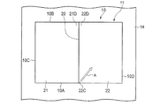
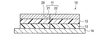
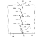
本発明の第1実施形態に係る擬似接着ラベルを図1〜3を用いて説明する。図1は、本発明の第1実施形態に係る擬似接着ラベルを模式的に示す平面図であり、図2はその断面図、図3は断裁線の部分拡大図である。
Hereinafter, embodiments of the present invention will be described with reference to the drawings.
The pseudo-adhesive label according to the first embodiment of the present invention will be described with reference to FIGS. FIG. 1 is a plan view schematically showing a pseudo-adhesive label according to the first embodiment of the present invention, FIG. 2 is a sectional view thereof, and FIG. 3 is a partially enlarged view of a cutting line.
図1に示すように、本発明の実施形態に係る擬似接着ラベル10は、略中央部にミシン目状の断裁線20を備えた表面基材11を備え、図2に示すように、表面基材11の裏面に擬似接着される擬似接着層12、擬似接着層12の裏面に接着された粘着剤層13がこの順に積層された積層構造を備える。粘着剤層13の裏面には剥離基材14が貼着されており、擬似接着ラベル10は、剥離基材14が粘着剤層13から剥離され、露出した粘着剤層13によって、被着物(図示せず)に貼着されて使用される。擬似接着層12は、表面基材11の裏面に剥離可能に擬似接着されており、被着物に貼着された状態で、表面基材11は擬似接着層12から剥離される。
As shown in FIG. 1, a
断裁線20は、表面基材11を左右の矩形シート(これらをラベル部21、22という)に分離して擬似接着層12から剥離可能とするために設けられる。本実施形態では、断裁線20は、表面基材11の下辺10Aから上辺10Bまで直線的に縦方向に延在する。
The
断裁線20は、縦方向に沿って間隔を置いて形成された複数の直線状の切れ目によってミシン目状に形成される。図3に断裁線20の部分拡大図として、第1の切れ目201、第2の切れ目202、第3の切れ目203を示す。各切れ目201、202、203は、それぞれ長さaの直線であり、断裁線20の方向に対して角度αとなるように、斜め方向に形成されており、かつ、互いに平行に離間距離bで離間配置される。
The
断裁線20は、このように配置された切れ目201、202、203が、縦方向に沿って連続して形成される。そして、断裁線20の最下端に配置される切れ目201の下端201aは、表面基材11の外縁である下辺10Aに接続する。同様に、断裁線20の最上端に配置される切れ目(不図示)の上端も、上辺10Bに接続する。
In the
図3に示すように、本実施形態では、断裁線20を縦に見たときに、隣り合う上下の切れ目201、202において、上側の切れ目202の下端202aよりも、下側の切れ目201の上端201bが高い位置にある。すなわち、切れ目201の上端201bは、断裁線20に沿う方向において、次の切れ目202の下側部分にオーバーラップする。隣り合う切れ目202、203も同様である。
As shown in FIG. 3, in this embodiment, when the
図3において破線で示す直線L1は、各切れ目201、202、203の下端201a、202a、203aを結ぶ直線であり、断裁線20の方向と平行である。同様に、図3において破線で示す直線L2は、各切れ目201、202、203の上端201b、202b、203bを結ぶ直線であり、断裁線20の方向と平行である。このように、各切れ目201、202、203の両端部を結ぶ直線L1、L2が互いに平行となるように、切れ目201、202、203は配置される。そして、断裁線20は、全体として、直線L1、L2によって画成された一条の帯状の領域となる。
A straight line L1 indicated by a broken line in FIG. 3 is a straight line connecting the lower ends 201a, 202a, and 203a of the cut lines 201, 202, and 203, and is parallel to the direction of the cutting
各切れ目201、202、203は、図2に示すように、表面基材11の表面から切り込まれて、表面基材11、擬似接着層12、及び粘着剤層13を貫通するものである。ただし、各切れ目は、表面基材11を貫通していれば、擬似接着層12及び粘着剤層13は切り込まれていなくても良い。
As shown in FIG. 2, the
各切れ目の長さaは、0.2mm以上20mm未満であることがより好ましい。切れ目が長すぎると、剥離基材14を粘着剤層13から剥離する際に、擬似接着ラベル10が断裁線20で折れ曲がりやすくなる場合がある。一方、切れ目が短すぎると断裁線20以外の箇所で表面基材11が破れる恐れがある。
The length a of each cut is more preferably 0.2 mm or more and less than 20 mm. If the cut is too long, the
離間距離bは、0.1mm以上1.5mm未満であることがより好ましい。離間距離が狭すぎると、剥離基材14を粘着剤層13から剥離する際に、擬似接着ラベル10が断裁線20で折れ曲がりやすくなる場合がある。一方、離間距離が広すぎると断裁線20以外の箇所で表面基材11が破れる恐れがある。
The separation distance b is more preferably 0.1 mm or more and less than 1.5 mm. If the separation distance is too narrow, the
角度αは、30度以上80度未満であることが好ましい。角度αが小さすぎると、剥離基材14を粘着剤層13から剥離する際に、擬似接着ラベル10が断裁線20で折れ曲がりやすくなる場合がある。一方、角度αが大きすぎると、断裁線20以外の箇所で表面基材11が破れる恐れがある。
The angle α is preferably 30 degrees or more and less than 80 degrees. If the angle α is too small, the
表面基材11は、例えば上質紙、熱転写用紙、クラフト紙、グラシン紙、感熱紙、合成紙、又はプラスティックフィルムが使用される。表面基材11の厚みは、例えば15〜120μm、好ましくは20〜110μmであり、更に好ましくは30〜100μmである。表面基材11は、例えばその表面が文字等の情報が表示されるための面に使用される。
As the
擬似接着層12は、表面基材11に剥離可能に擬似接着されるものであれば、特に限定されないが、熱可塑性樹脂層であることが好ましい。熱可塑性樹脂層は、例えば、加熱溶融された熱可塑性樹脂が表面基材11の裏面に押出積層されることにより形成される。熱可塑性樹脂層を形成するための熱可塑性樹脂としては、例えば、ポリエチレン、ポリプロピレン、ポリメチルペンテン等が単独で又は2種類以上混合されて使用される。熱可塑性樹脂層の厚さは、特に限定されないが、例えば3〜70μm、好ましくは5〜50μmである。
The
表面基材11の裏面には、擬似接着層12から表面基材11を容易に剥離できるように、離型剤層が被膜されていても良い。離型剤層は、特に限定されないが、スチレン−アクリル共重合体、ポリスチレン、スチレン−ブタジエン共重合体、エチレン酢酸ビニル共重合体、アクリル酸エステル、アクリル酸エステル共重合体、エチレン・アクリル酸共重合体などからなる離型剤によって形成される。なお、表面基材11は、離型剤層が設けられる場合には、擬似接着層12と離型剤層との界面で剥離される。また、表面基材11は、その裏面にさらに上記熱可塑性樹脂で形成された熱可塑性樹脂層と、離型剤層とがこの順に設けられたものであっても良い。
A release agent layer may be coated on the back surface of the
粘着剤層13は、擬似接着層12の裏面側に設けられ、擬似接着ラベル10を被着物に粘着させるための層であって、アクリル系粘着剤、天然ゴム系粘着剤、合成ゴム系粘着剤、シリコーン系粘着剤等の従来公知の粘着剤から形成される。粘着剤層13の厚さは、特に限定されないが、例えば5〜50μm、好ましくは10〜40μmである。剥離基材14は、粘着剤層13に貼着されるための表面がシリコーン系剥離剤等によって離型処理された剥離シート等である。
The pressure-
粘着剤層13は、例えば、剥離基材14の表面に粘着剤が塗布されて形成される。そして、その剥離基材14の上に形成された粘着剤層13に、表面基材11の上に積層された擬似接着層12が貼り合わされることにより、擬似接着ラベル10が得られる。但し、粘着剤層13は、表面基材11に積層されている擬似接着層12の裏面の上に直接塗布して形成され、その上に剥離基材14が貼り合わされて擬似接着ラベル10が形成されても良い。
The pressure-
次に、擬似接着ラベル10の打ち抜き加工及び断裁線20の加工について説明する。図1に示すように、擬似接着ラベル10は、打ち抜き加工が施されることにより、表面基材11、擬似接着層12、及び粘着剤層13が打ち抜き切断された後、カス上げによって不要部分が剥離基材14から取り除かれ、下辺10A及び上辺10Bを長辺とし、左右の側辺10C、10Dを短辺とする略矩形のラベルに形成される。打ち抜き加工と共に略中央部に断裁線20を入れるためのミシン目加工が施され、粘着剤層13まで打ち抜き切断されることにより、表面基材11の略中央部にミシン目状の断裁線20が形成される。
Next, the punching process of the
打ち抜き加工及びミシン目加工は、例えば、凸状押切刃を回転駆動ローラの表面に設けたダイカッタを用いるダイカットによって行われる。なお、打ち抜き加工及びミシン目加工は、レーザー照射等によって行われても良い。 The punching process and the perforation process are performed, for example, by die cutting using a die cutter in which a convex pressing blade is provided on the surface of the rotary drive roller. The punching process and the perforation process may be performed by laser irradiation or the like.
次に、擬似接着ラベル10における表面基材11の剥離方法について説明する。
Next, the peeling method of the
本発明の第1実施形態に係る擬似接着ラベル10において、図1に示すラベル部22の切り離しは、例えば、下辺10Aと断裁線20が交差する位置にあるラベル部22の角部22Cを剥離開始部として摘まんで、ラベル部22を剥離方向Aに引き剥がすことにより行う。角部22Cを摘まんで矢印Aの方向に引き剥がすと、ラベル部22は、図3に示す第1の切れ目201の下端201aから第1の切れ目201に沿って剥離される。ラベル部22が第1の切れ目201の上端201bまで剥離されると、第1の切れ目201の上端201bから剥離方向Aに沿う方向に表面基材11が破断される。ここで剥離方向Aは、切れ目201、202の傾斜する方向に交わる方向であり、切れ目201の上端201bの剥離方向Aの延長線上には、次の切れ目202が配置されている。そのため、上記破断は、剥離方向Aに沿う方向に進むことにより第2の切れ目202に到達する。
In the
その後同様に、各切れ目の間の離間部分が連続的に破断され、ラベル部22は剥離される。つまり、ラベル部22は、ラベル部21側を擬似接着層12上に残した状態で、直線L1、L2によって画成された断裁線20の帯状領域のみで断裁されながら擬似接着層12から剥離される。
Thereafter, similarly, the separated portion between the cuts is continuously broken, and the
本発明の第1実施形態に係る擬似接着ラベル10によれば、表面基材11をラベル部21、22に分離して剥離する際に、断裁線20の帯状領域以外で表面基材11に破れが発生することなく、容易に擬似接着層12から剥離することができる。また、断裁線20に沿ってラベル部21、22を2つに分離しながら容易に剥離できるため、表面基材11の紙の流れ方向やフィルムの延伸方向に関係なく剥離可能となり、断裁線20が流れ方向や延伸方向に対して垂直に形成されている場合であっても表面基材11が破れにくくなる。
According to the
また、断裁線20では、各切れ目201、202、203が断裁線20の方向に対して斜め方向に形成されているため、擬似接着ラベル10が断裁線20で折れ曲がりにくくなる。さらに、各切れ目の端部が、次の切れ目とオーバーラップするため、断裁線以外の箇所で表面基材に破れが発生しにくくなる。
In the
なお、本実施形態では、上記したように、各切れ目201、202、203の斜め方向は剥離する方向に交わらないと、ラベル部を剥離することは難しい。すなわち、上記実施形態では、上辺10Bと断裁線20が交差する位置にあるラベル部22の角部22Dを剥離開始部として、ラベル部22を剥離することは難しい。そのため、表面基材11等にマーク等が付されて、例えば、角部22Cがラベル部22の剥離開始部であることが示されていても良い。また、表面基材11上に剥離方向Aを示した矢印が付されても良い。
In the present embodiment, as described above, it is difficult to peel off the label part unless the oblique directions of the cut lines 201, 202, and 203 intersect with the peeling direction. That is, in the above-described embodiment, it is difficult to peel off the
また、本発明の実施形態において、ラベル部22を先に剥離したが、ラベル部21を先に剥離しても構わない。この際、ラベル部21は、上辺10Bと断裁線20が交差する角部21Dを剥離開始部として剥離されることにより、上記したように断裁線20に沿って剥離されることになる。ラベル部21も、ラベル部22と同様に、剥離方向が各切れ目201、202、203の斜め方向に交わらないと剥離が困難であるため、角部21Dを剥離開始部として示すマークや、剥離方向を示す矢印等が付されても良い。
In the embodiment of the present invention, the
なお、擬似接着ラベル10は、2つのラベル部のうち、いずれのラベル部が先に剥離されるかが予め決まっている場合がある。例えば、擬似接着ラベルが配送伝票に使用され、ラベル部22が受領票、ラベル部21が配達票とされると、ラベル部22が先に剥離されることとなる。このような場合、ラベル部22を角部22Cから剥離しやすくするために、断裁線20の下端における切れ目201は、下辺10Aに接続する必要があるが、上端における切れ目は、上辺10Bに接続する必要はない。
In some cases, the
また、各切れ目201、202、203は、本実施形態では直線状に形成されているが、例えば、外側又は内側に湾曲する曲線であっても構わない。また、各切れ目201、202、203の断裁線20の方向に対する角度αは、適宜設定することが好ましい。また、各切れ目201、202、203の間隔は均等でも非均等であっても構わないし、断裁線20は、曲線であっても構わない。
Moreover, although each cut |
なお、隣り合う切れ目のオーバーラップする範囲を適宜設定することにより、様々な剥離方向に対して、断裁線以外の箇所で表面基材が破れることを防止することが可能となる。 In addition, it becomes possible to prevent that a surface base material is torn at places other than a cutting line with respect to various peeling directions by appropriately setting the overlapping range of adjacent cuts.
また、各切れ目201、202、203の上端201b、202b、203bの剥離方向Aの延長線上に、次の切れ目が配置されれば本発明の課題が解決する。このため、ある程度剥離方向Aが限定される場合には、各切れ目201、202、203の上端201b、202b、203bの剥離方向Aの延長線上に次の切れ目の下端201a、202a、203aが位置するように配置すれば良い。この場合には、断裁線20における切込箇所が少なくなるため、表面基材11を剥離する際に、表面基材11の自重により切込部分で折れ曲がることを防止する効果が高くなる。このように、各切れ目201、202、203の長さ、断裁線の方向に対する角度、切れ目201、202、203の間の間隔等は、本発明を適用する擬似接着ラベルに応じて適宜設計可能である。
Moreover, if the next cut | interruption is arrange | positioned on the extension line | wire of the peeling direction A of each
次に、本発明の第2実施形態に係る擬似接着ラベルを図を用いて説明する。第2実施形態では、断裁線20を構成する複数の切れ目の形状が第1実施形態と異なっている。以下、第2の実施形態について第1の実施形態との相違点について説明する。
Next, a pseudo adhesive label according to a second embodiment of the present invention will be described with reference to the drawings. In the second embodiment, the shapes of the plurality of cut lines constituting the cutting
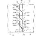
図4に第2実施形態に係る擬似接着ラベルの断裁線20の部分拡大図として、第1の切れ目230、第2の切れ目240、第3の切れ目250を示す。図4に示すように、各切れ目230、240、250は、断裁線20の方向に沿う第1の直線部231、241、251と、第1の直線部231、241、251の上端231b、241b、251bに連接する斜線部232、242、252と、斜線部232、242、252の上端232b、242b、252bに連接し、第1の直線部231、241、251と平行な第2の直線部233、243、253とをそれぞれ備えたクランク状の屈曲線である。各切れ目230、240、250は、下端231a、241a、251aと上端233b、243b、253bとを結んだ直線が断裁線20に沿う方向と交差するように配置する。
FIG. 4 shows a
第1の直線部231、241、251は、それぞれ長さgである。斜線部232、242、252はそれぞれ長さhであり、断裁線20の方向に対して角度αとなるように傾斜した状態で、互いに平行に離間配置される。第2の直線部233、243、253は、それぞれ長さiである。第1の直線部231、241、251と第2の直線部233、243、253とは、離間距離jで、互いに平行に離間配置される。すなわち、第1の切れ目230の第2の直線部233と、第2の切れ目240の第1の直線部241とは、互いに平行で、かつ一部が断裁線20の方向においてオーバーラップするように対向配置される。同様に、第2の切れ目240の第2の直線部243と、第3の切れ目250の第1の直線部251とは、互いに平行であり、かつ一部が断裁線の方向に沿ってオーバーラップするように互いに平行に離間配置される。このようにして、断裁線20は、全体として、直線L1、L2によって画成された一条の帯状の領域となる。
The first
図4において直線L1は、各切れ目230、240、250の下端231a、241a、251aを含む第1の直線部231、241、251を結ぶ直線であり、断裁線の方向と平行である。同様に、図4において直線L2は、各切れ目230、240、250の上端233b、243b、253bを含む第2の直線部233、243、253を結ぶ直線であり、断裁線の方向と平行である。このように、直線L1、L2が互いに平行となるように、切れ目230、240、250は配置される。
In FIG. 4, a straight line L1 is a straight line connecting the first
断裁線20は、このように配置された切れ目230、240、250が、縦方向に沿って連続して形成される。また、断裁線20の両方の端部における切れ目は、第1の実施形態と同様に、下辺10A及び上辺10Bに接続する。
In the
各切れ目の全体の長さは、0.5mm以上20mm未満であることが好ましい。切れ目が長すぎると、剥離基材14を粘着剤層13から剥離する際に、擬似接着ラベル10が断裁線20で折れ曲がりやすくなる場合がある。一方、切れ目が短すぎると断裁線20以外の箇所で表面基材11が破れる恐れがある。
The total length of each cut is preferably 0.5 mm or more and less than 20 mm. If the cut is too long, the
離間距離jは、0.2mm以上5mm未満であることが好ましい。離間距離が狭すぎると、剥離基材14を粘着剤層13から剥離する際に、擬似接着ラベル10が断裁線20で折れ曲がりやすくなる場合がある。一方、離間距離が広すぎると断裁線20以外の箇所で表面基材11が破れる恐れがある。
The separation distance j is preferably 0.2 mm or more and less than 5 mm. If the separation distance is too narrow, the
角度αは、15度以上80度未満であることが好ましい。角度αが大きすぎると、剥離基材14を粘着剤層13から剥離する際に、擬似接着ラベル10が断裁線20で折れ曲がりやすくなる場合がある。一方、角度αが小さすぎると、断裁線20以外の箇所で表面基材11が破れる恐れがある。
The angle α is preferably 15 degrees or more and less than 80 degrees. When the angle α is too large, the
本実施形態でも、第1実施形態と同様に、ラベル部22が角部22Cから、切れ目の斜め方向に対して交わる剥離方向Aに引き剥がされることにより、切れ目の上端と次の切れ目の間が破断されつつ、断裁線20に沿ってラベル部22が剥離されることになる。ラベル部21が剥離される場合も同様である。
Also in this embodiment, as in the first embodiment, the
本実施形態においても、第1の実施形態と同様に、ラベル部21、22を剥離する際に、表面基材11の破れが防止されるとともに、剥離基材から剥がされた擬似接着ラベル10が断裁線20で折れ曲がりにくくなる。また、本実施形態では、断裁線20の方向と平行な第1の直線部231、241、251と第2の直線部233、243、253を有することにより、断裁面に凹凸ができにくくなる。
Also in the present embodiment, as in the first embodiment, when the
また、各切れ目230、240、250の直線部231、241、251、233、243、253は、例えば、外側又は内側に湾曲する曲線であっても構わない。また、各斜線部232、242、252の断裁線の方向に対する角度αは、適宜設定することが好ましい。また、各切れ目230、240、250の間隔は均等でも非均等であっても構わないし、断裁線20は、曲線であっても構わない。
In addition, the
なお、上記第1及び第2実施形態において、ラベル部21、22は略矩形であったが、その形状は矩形に限定されず、例えば三角形等他の多角形でも良いし、円形等であっても良い。矩形形状以外の場合であっても、断裁線20から表面基材11が剥離される。
In the first and second embodiments, the
また、切れ目の形状は上記実施形態に限定されない。例えば、直線とその一端に連続した斜線との組み合わせによる「へ」の字の形状を、直線が断裁線の方向に沿うように一列に断続的に形成したものや、波形線をその両端部が互いにオーバーラップするように一列に断続的に設けたものでも構わない。 Further, the shape of the cut is not limited to the above embodiment. For example, the shape of the letter “he” by a combination of a straight line and a diagonal line at one end thereof is formed intermittently in a line so that the straight line follows the direction of the cutting line, or a wavy line at both ends. What provided intermittently in a line so that it may mutually overlap may be used.
なお、擬似接着ラベル10の構造や材質は、上記実施形態に限定されない。例えば、表面基材11、擬似接着層12、粘着剤層13以外の層を備えたものであっても構わない。
The structure and material of the
次に、本発明について、以下実施例を用いて説明するが、本発明は以下の実施例の構成に限定されない。 Next, the present invention will be described below using examples, but the present invention is not limited to the configurations of the following examples.
[実施例1]
表面基材として、厚さ90μmの熱転写用紙(日本製紙社製、商品名:RT−C(N) W75G)を使用した。擬似接着層を形成するための熱可塑性樹脂として、ポリプロピレン(サンアロマー社製ポリプロピレン、商品名:サンアロマーPHA03A)を使用した。熱可塑性樹脂は、押出温度290℃、厚さ20μmとなるようにTダイにて押し出し、熱転写用紙の裏面に熱可塑性樹脂を積層して擬似接着シートとした。次に、シリコーン系剥離紙の離型剤面にアクリル系粘着剤を厚さ25μmになるように塗工して粘着剤層を形成し、先に形成した擬似接着シートの擬似接着層に貼り合わせた。その後、打ち抜き加工及びミシン目加工を行い、図1に示すような擬似接着ラベルを得た。擬似接着ラベルは、横150mm、縦100mmであって、横方向の中央に断裁線を設けた。断裁線を構成する各切れ目の形状は図3の形状とし、各切れ目の長さaを2.0mm、切れ目間の離間距離bを0.5mm、αは50度となるように打ち抜き加工した。なお、切れ目は粘着剤層を貫通するような深さとした。
[Example 1]
As the surface substrate, a thermal transfer paper (manufactured by Nippon Paper Industries Co., Ltd., trade name: RT-C (N) W75G) having a thickness of 90 μm was used. Polypropylene (polypropylene manufactured by Sun Allomer, trade name: Sun Allomer PHA03A) was used as the thermoplastic resin for forming the pseudo adhesive layer. The thermoplastic resin was extruded with a T-die so that the extrusion temperature was 290 ° C. and the thickness was 20 μm, and the thermoplastic resin was laminated on the back surface of the thermal transfer paper to obtain a pseudo adhesive sheet. Next, an acrylic pressure-sensitive adhesive is applied to the release agent surface of the silicone release paper to a thickness of 25 μm to form a pressure-sensitive adhesive layer, which is then bonded to the pseudo-adhesive layer of the previously formed pseudo-adhesive sheet. It was. Thereafter, punching and perforation were performed to obtain a pseudo-adhesive label as shown in FIG. The pseudo-adhesive label was 150 mm wide and 100 mm long, and a cut line was provided at the center in the horizontal direction. The shape of each cut forming the cutting line was the shape shown in FIG. 3, and the length a of each cut was 2.0 mm, the separation distance b between the cuts was 0.5 mm, and α was 50 degrees. The cuts were deep enough to penetrate the pressure-sensitive adhesive layer.
[実施例2]
表面基材として、厚さ60μmの合成紙(ユポ・コーポレーション社製、商品名:ユポタック原紙 60SGS)を用いた以外は、実施例1と同様に実施した。
[Example 2]
The same procedure as in Example 1 was performed except that synthetic paper (manufactured by YUPO Corporation, trade name: YUPOTAC base paper 60SGS) having a thickness of 60 μm was used as the surface substrate.
[実施例3]
熱可塑性樹脂として、低密度ポリエチレン(住友化学社製、商品名:スミカセンL−405H)を用いた以外は、実施例1と同様に実施した。
[Example 3]
It implemented similarly to Example 1 except having used low density polyethylene (The Sumitomo Chemical Co., Ltd. make, brand name: Sumikasen L-405H) as a thermoplastic resin.
[実施例4]
断裁線を構成する各切れ目の形状は図3の形状とし、各切れ目の長さaを5mm、切れ目間の離間距離bを0.8mm、αは40度となるように打ち抜き加工した以外は、実施例1と同様に実施した。
[Example 4]
The shape of each cut forming the cutting line is the shape of FIG. 3, except that the length a of each cut is 5 mm, the separation distance b between the cuts is 0.8 mm, and the punching process is performed so that α is 40 degrees. The same operation as in Example 1 was performed.
[実施例5]
断裁線を構成する各切れ目の形状は図3の形状とし、各切れ目の長さaを8mm、切れ目間の離間距離bを1.0mm、αは30度となるように打ち抜き加工した以外は、実施例1と同様に実施した。
[Example 5]
The shape of each cut constituting the cutting line is the shape of FIG. 3, except that the length a of each cut is 8 mm, the separation distance b between the cuts is 1.0 mm, and the punching process is performed so that α is 30 degrees. The same operation as in Example 1 was performed.
[実施例6]
断裁線を構成する各切れ目の形状を図4の形状とし、各切れ目の第1及び第2の直線部g、iの長さを1.0mm、切れ目間の離間距離jを0.5mm、αは45度となるように打ち抜き加工した以外は、実施例2と同様に実施した。
[Example 6]
The shape of each cut constituting the cutting line is the shape shown in FIG. 4, the length of the first and second straight portions g, i of each cut is 1.0 mm, the distance j between the cuts is 0.5 mm, α Was carried out in the same manner as in Example 2 except that punching was performed to 45 degrees.
[実施例7]
断裁線を構成する各切れ目の形状を図4の形状とし、各切れ目の第1及び第2の直線部g、iの長さを2.0mm、切れ目間の離間距離jを1.0mm、αは30度となるように打ち抜き加工した以外は、実施例2と同様に実施した。
[Example 7]
The shape of each cut forming the cutting line is the shape shown in FIG. 4, the length of the first and second straight portions g, i of each cut is 2.0 mm, the distance j between the cuts is 1.0 mm, α Was carried out in the same manner as in Example 2 except that punching was performed to 30 degrees.
[実施例8]
断裁線を構成する各切れ目の形状を図4の形状とし、各切れ目の第1及び第2の直線部g、iの長さを5.0mm、切れ目間の離間距離jを1.5mm、αは60度となるように打ち抜き加工した以外は、実施例2と同様に実施した。
[Example 8]
The shape of each cut forming the cutting line is the shape of FIG. 4, the length of the first and second straight portions g, i of each cut is 5.0 mm, the separation distance j between the cuts is 1.5 mm, α Was carried out in the same manner as in Example 2 except that punching was performed so as to be 60 degrees.
[実施例9]
実施例6の断裁線を構成する各切れ目の形状を、第1の直線部と斜線部との連結部並びに斜線部と第2の直線部との連結部がスムーズな曲線で結ばれた略波形状に打ち抜き加工した以外は、実施例6と同様に実施した。
[Example 9]
The shape of each cut line constituting the cutting line of Example 6 is a substantially wave in which the connecting portion between the first straight portion and the oblique portion and the connecting portion between the oblique portion and the second straight portion are connected by a smooth curve. The same operation as in Example 6 was performed except that the shape was punched.
[比較例1]
断裁線をミシン目状ではなく上辺から下辺まで延在する一条の縦線とし、切れ目の深さを表面基材の厚みと同一とし、表面基材のみを貫通する深さとした以外は、実施例1と同様に実施した。
[Comparative Example 1]
Example, except that the cutting line is not a perforated line but a single vertical line extending from the upper side to the lower side, the depth of the cut is the same as the thickness of the surface base material, and the depth penetrates only the surface base material 1 was carried out.
[比較例2]
断裁線を構成する各切れ目が断裁線の方向に沿う直線のみで形成されたミシン目とした以外は、実施例1と同様に実施した。各切れ目の長さは0.7mm、切れ目間の離間距離は0.3mmとした。
[Comparative Example 2]
The process was performed in the same manner as in Example 1 except that each cut forming the cutting line was a perforation formed only by a straight line along the direction of the cutting line. The length of each cut was 0.7 mm, and the distance between the cuts was 0.3 mm.
[評価方法]
(1)擬似側剥離試験
実施例及び比較例で得られた擬似接着ラベルの剥離基材を引き剥がして除去し、被着物である台紙に粘着剤層を貼着した。この状態で、図1に示す角部22Cから表面基材11のラベル部22を矢印A方向に剥離角度180°で剥離する試験を10回行い、表面基材を破かずに断裁線に沿って剥がすことができるかを評価した。表面基材の破れが発生した回数を、剥離不良率(破れが発生した回数/試験回数×100)で表し、剥離不良率20%未満を○(良好)、剥離不良率20%以上を×(不良)と評価した。
[Evaluation method]
(1) Pseudo-side peeling test The peeling base material of the pseudo-adhesive label obtained in Examples and Comparative Examples was peeled off and removed, and an adhesive layer was attached to a backing paper as an adherend. In this state, the test of peeling the
(2)作業性確認試験
実施例及び比較例で得られた擬似接着ラベルについて、剥離基材を引き剥がして除去して、被着物である台紙に貼着する作業性を確認した。作業性が良好なものを○、作業し難いものを×として評価した。表1に、実施例及び比較例で得られた擬似接着ラベルの評価試験の結果を示す。
(2) Workability confirmation test For the pseudo-adhesive labels obtained in the examples and comparative examples, the peelable substrate was peeled off and removed, and the workability of attaching to the backing sheet as the adherend was confirmed. A sample having good workability was evaluated as ○, and a sample having difficulty in work was evaluated as ×. Table 1 shows the results of the evaluation test of the pseudo-adhesive labels obtained in the examples and comparative examples.

表面基材にミシン目状ではなく、一条の縦の切込を入れた比較例1では、擬似側剥離試験では問題なかったが、作業性確認試験では擬似接着ラベルの剥離基材を引き剥がすと表面基材の自重により切込部分で折れ曲がり、作業し難かった。また、断裁線が通常のミシン目形状とした比較例2は、作業性確認試験では表面基材が折れ曲がることなく、作業性に問題はなかったが、擬似側剥離試験では断裁線に沿って表面基材を切り難く、強く剥離しようとすると表面基材の破れが発生した。 In Comparative Example 1 in which the surface base material was not perforated but a single vertical notch, there was no problem in the pseudo side peeling test, but in the workability confirmation test, the peeling base material of the pseudo adhesive label was peeled off. It was difficult to work because it was bent at the notch due to its own weight. Further, in Comparative Example 2 in which the cutting line had a normal perforation shape, the surface base material was not bent in the workability confirmation test, and there was no problem in workability, but the surface along the cutting line in the pseudo side peeling test. It was difficult to cut the substrate, and the surface substrate was torn when trying to peel strongly.
これに対し、実施例1〜9では、いずれも表面基材に破れが発生することなく擬似接着層から剥離することができ、更に作業性が良好だった。このように、断裁線を構成する切れ目の少なくとも一部が、断裁線の方向に対して所定角度傾斜した状態となるように設けたことにより、表面基材を断裁線で分離して剥離する際に、表面基材に破れが発生することなく擬似接着層から剥離することができ、更に表面基材が折れ曲がることなく、作業性の良い擬似接着ラベルを得ることができた。 On the other hand, in Examples 1-9, all were able to peel from a pseudo-adhesion layer, without generating a tear in a surface base material, and also workability | operativity was favorable. As described above, when the surface substrate is separated and separated by the cutting line by providing at least a part of the cut line constituting the cutting line so as to be inclined at a predetermined angle with respect to the direction of the cutting line. In addition, it was possible to peel the surface base material from the pseudo-adhesive layer without causing breakage, and further to obtain a pseudo-adhesive label with good workability without the surface base material being bent.
10 擬似接着ラベル
11 表面基材
12 擬似接着層
13 粘着剤層
14 剥離基材
20 断裁線
21、22 ラベル部
201、202、203、230、240、250 切れ目
DESCRIPTION OF
Claims (4)
前記表面基材は、少なくとも2以上のラベル部に分離して前記擬似接着層から剥離可能とするためのミシン目状の断裁線を備え、
前記断裁線は、線状の切れ目が間隔を置いて形成され、
前記切れ目の少なくとも一部が、前記断裁線の方向に対して斜め方向に形成されていることを特徴とする擬似接着ラベル。 A surface base material, a pseudo-adhesive layer that is pseudo-adhered to the surface base material, and a pressure-sensitive adhesive layer are provided in this order, and the pressure-sensitive adhesive layer is attached to an adherend, A pseudo-adhesive label capable of peeling the surface substrate from the pseudo-adhesive layer,
The surface base material is provided with a perforated cut line for separating into at least two or more label portions and making the peelable peelable layer peelable.
The cutting line is formed with a linear cut at intervals,
The pseudo-adhesive label, wherein at least a part of the cut is formed in an oblique direction with respect to the direction of the cutting line.
前記切れ目の上端を結ぶ直線と下端を結ぶ直線とが、前記断裁線に平行であることを特徴とする請求項2に記載の擬似接着ラベル。 The cut is a straight line arranged in parallel,
The pseudo-adhesive label according to claim 2, wherein a straight line connecting the upper ends of the cuts and a straight line connecting the lower ends are parallel to the cutting line.
The pseudo-adhesive label according to claim 1 or 2, wherein the cut includes a straight line portion along a cutting line direction and a hatched portion connected to one end of the straight line portion.
Priority Applications (1)
| Application Number | Priority Date | Filing Date | Title |
|---|---|---|---|
| JP2012010021A JP2012194532A (en) | 2011-03-02 | 2012-01-20 | Pseudo adhesive label |
Applications Claiming Priority (3)
| Application Number | Priority Date | Filing Date | Title |
|---|---|---|---|
| JP2011045535 | 2011-03-02 | ||
| JP2011045535 | 2011-03-02 | ||
| JP2012010021A JP2012194532A (en) | 2011-03-02 | 2012-01-20 | Pseudo adhesive label |
Publications (1)
| Publication Number | Publication Date |
|---|---|
| JP2012194532A true JP2012194532A (en) | 2012-10-11 |
Family
ID=47086445
Family Applications (1)
| Application Number | Title | Priority Date | Filing Date |
|---|---|---|---|
| JP2012010021A Pending JP2012194532A (en) | 2011-03-02 | 2012-01-20 | Pseudo adhesive label |
Country Status (1)
| Country | Link |
|---|---|
| JP (1) | JP2012194532A (en) |
Cited By (1)
| Publication number | Priority date | Publication date | Assignee | Title |
|---|---|---|---|---|
| JP2015208861A (en) * | 2014-04-23 | 2015-11-24 | 大日本印刷株式会社 | Delivery slip |
Citations (5)
| Publication number | Priority date | Publication date | Assignee | Title |
|---|---|---|---|---|
| JPH0278598A (en) * | 1988-09-14 | 1990-03-19 | Daimatsu Kagaku Kogyo Kk | Postcard |
| JPH0279076A (en) * | 1988-09-14 | 1990-03-19 | Daimatsu Kagaku Kogyo Kk | Adhesive material |
| JP2008073970A (en) * | 2006-09-21 | 2008-04-03 | Dainippon Printing Co Ltd | Concealed postcard |
| JP2008230099A (en) * | 2007-03-22 | 2008-10-02 | Dainippon Printing Co Ltd | Pressure-bonded postcard |
| JP2010175649A (en) * | 2009-01-27 | 2010-08-12 | Lintec Corp | Label laminate, method of manufacturing label laminate, delivery slip and method of preparing delivery slip |
-
2012
- 2012-01-20 JP JP2012010021A patent/JP2012194532A/en active Pending
Patent Citations (5)
| Publication number | Priority date | Publication date | Assignee | Title |
|---|---|---|---|---|
| JPH0278598A (en) * | 1988-09-14 | 1990-03-19 | Daimatsu Kagaku Kogyo Kk | Postcard |
| JPH0279076A (en) * | 1988-09-14 | 1990-03-19 | Daimatsu Kagaku Kogyo Kk | Adhesive material |
| JP2008073970A (en) * | 2006-09-21 | 2008-04-03 | Dainippon Printing Co Ltd | Concealed postcard |
| JP2008230099A (en) * | 2007-03-22 | 2008-10-02 | Dainippon Printing Co Ltd | Pressure-bonded postcard |
| JP2010175649A (en) * | 2009-01-27 | 2010-08-12 | Lintec Corp | Label laminate, method of manufacturing label laminate, delivery slip and method of preparing delivery slip |
Cited By (1)
| Publication number | Priority date | Publication date | Assignee | Title |
|---|---|---|---|---|
| JP2015208861A (en) * | 2014-04-23 | 2015-11-24 | 大日本印刷株式会社 | Delivery slip |
Similar Documents
| Publication | Publication Date | Title |
|---|---|---|
| JP5699330B2 (en) | Delivery slip | |
| JP6089448B2 (en) | Delivery slip | |
| JP2001353987A (en) | Delivery slip | |
| JP4487100B2 (en) | Information protection seal | |
| JP2014040005A (en) | Delivery slip | |
| JP2004034673A (en) | Combined information sheet | |
| JP5962216B2 (en) | Delivery slip | |
| JP5730618B2 (en) | Pseudo adhesive label | |
| JP2016153857A (en) | Label sheet | |
| JP5602359B2 (en) | Delivery label slip | |
| JP2012194532A (en) | Pseudo adhesive label | |
| JP2012208470A (en) | Pseudo adhesive label | |
| JP2010046953A (en) | False adhesive label and method of manufacturing same | |
| JP3178213U (en) | Delivery slip | |
| JP5064327B2 (en) | Pseudo adhesive label | |
| JP7131202B2 (en) | laminated sheet | |
| JP2012189946A (en) | Pseudo adhesive label | |
| JP2013244721A (en) | Delivery slip | |
| JP2012189738A (en) | Pseudo adhesive label | |
| JP2006071857A (en) | Sticker label | |
| JP2014040006A (en) | Delivery slip | |
| JP2004291293A (en) | Business form for delivery slip | |
| JP2020006590A (en) | Laminated sheet | |
| JP6929663B2 (en) | label | |
| JP3132073U (en) | Label paper |
Legal Events
| Date | Code | Title | Description |
|---|---|---|---|
| A621 | Written request for application examination |
Free format text: JAPANESE INTERMEDIATE CODE: A621 Effective date: 20150108 |
|
| A977 | Report on retrieval |
Free format text: JAPANESE INTERMEDIATE CODE: A971007 Effective date: 20160308 |
|
| A131 | Notification of reasons for refusal |
Free format text: JAPANESE INTERMEDIATE CODE: A131 Effective date: 20160315 |
|
| A02 | Decision of refusal |
Free format text: JAPANESE INTERMEDIATE CODE: A02 Effective date: 20161213 |