JP6089448B2 - Delivery slip - Google Patents
Delivery slip Download PDFInfo
- Publication number
- JP6089448B2 JP6089448B2 JP2012122049A JP2012122049A JP6089448B2 JP 6089448 B2 JP6089448 B2 JP 6089448B2 JP 2012122049 A JP2012122049 A JP 2012122049A JP 2012122049 A JP2012122049 A JP 2012122049A JP 6089448 B2 JP6089448 B2 JP 6089448B2
- Authority
- JP
- Japan
- Prior art keywords
- delivery slip
- slip
- cut
- delivery
- peeling
- Prior art date
- Legal status (The legal status is an assumption and is not a legal conclusion. Google has not performed a legal analysis and makes no representation as to the accuracy of the status listed.)
- Active
Links
Images


Description
本発明は、配送伝票に関し、さらに詳しくは、配送伝票の配達票などの剥離可能な剥離片でも製造中、プリンタでの印字中、輸送などの運用中でも捲れや脱落が生じ難く、また製造から運用における環境の変化でも捲れや脱落が生じ難い配送伝票に関するものである。 The present invention relates to a delivery slip, and more particularly, even when a peelable peelable piece such as a delivery slip of a delivery slip is being manufactured, printed on a printer, or transported, it is difficult to bend or drop off, and it can be used from manufacturing. This relates to a delivery slip that is unlikely to be drowned or dropped even when the environment changes.
本明細書において、配合を示す「比」、「部」、「%」などは特に断わらない限り質量基準であり、「/」印は一体的に積層されていることを示す。 In the present specification, “ratio”, “part”, “%” and the like indicating the composition are based on mass unless otherwise specified, and the “/” mark indicates that they are integrally laminated.
(背景技術)従来、配送伝票は、少なくとも配達票と貼付票とで構成され、配達票は剥離可能に、貼付票は強接着状態で、基材又はラベル用紙に接着層を介して積層されている。しかしながら、配送伝票の配達票などの剥離可能な剥離片は、製造中、プリンタでの印字中、輸送などの運用中、又は製造から運用における環境の変化によって捲れや脱落が生じる恐れがある。 (Background Art) Conventionally, a delivery slip is composed of at least a delivery slip and a sticker slip, the delivery slip is peelable, the sticker slip is in a strongly bonded state, and is laminated on a base material or label paper via an adhesive layer. Yes. However, a peelable peelable piece such as a delivery slip of a delivery slip may be drowned or dropped during manufacturing, during printing with a printer, during operation such as transportation, or due to changes in the environment from manufacturing to operation.
(従来技術)従来、裏面が貼着面となった貼着シートの表面に、表面に配送情報印字部を有する印字シートを接着剤で接着してなる配送票を、印字時の移送方向に複数連接してなる印字用配送票であって、前記貼着シートと前記印字シートの接着面の少なくとも一方の所定部分には、この接着面の周縁の少なくとも移送方向に直交する二辺に沿って間隔をおいて存する複数の非設置部分を形成した接着剤遮蔽層を設けて前記接着面を剥離可能となすとともに、移送方向に隣接する各配送票において互いの連接辺に沿って設けた接着剤遮蔽層の非設置部分同士を、移送方向と直交する方向に相対的にずらして形成した印字用配送票(請求項1)が知られている(例えば、特許文献1参照。)。また、表面に配送情報記入部を有する貼付票と、同じく表面に配送情報記入部を有する配達票兼受領票と、同じく表面に配送品名記入部を有する配送品名記入票とを、貼着シートの表面に接着剤で接着する一方、前記貼着シートの裏面には粘着剤を塗布するとともに剥離紙で被覆し、前記配達票兼受領票は前記貼着シートの対応部分に対して剥離可能に構成し、前記配送品名記入票は前記貼着シート及び剥離紙の対応部分とともに分離可能に構成し(請求項1)、貼着シートに対する配達票兼受領票及び配送品名記入票の剥離可能な構成は、接着面の少なくとも一方に接着剤遮蔽層を設けてなる(請求項3)配送票が知られている(例えば、特許文献2参照。)。さらに、少なくとも2枚の基材を備え、基材間の一部領域に剥離層を介在させて両基材を接着剤で貼り合わせてなる部分的に剥離可能な部分を有する貼り合わせシートにおいて、前記剥離可能な部分の剥離する際の終端側となる最外側の少なくとも一部に狭幅の剥離層のない部分を設け、その剥離層のない部分で接着剤が基材面に直接接するようにした貼り合わせシート(請求項1)が知られている(例えば、特許文献3参照。)。しかしながら、特許文献1〜3では、剥離可能な剥離片の剥離開始部は剥離力が低いので、製造中、プリンタでの印字中、輸送などの運用中、又は製造から運用における環境の変化によって捲れや脱落が生じる恐れがある。さらにまた、所定方向に延長する辺を具備するスリットに囲まれることによって分離可能となる分離領域が区画形成された第1のシートと、該第1のシートに貼着された第2のシートとを有し、前記所定方向と直交する方向に引張力が加わる分離シートにおいて、前記スリットは、前記所定方向に延長する辺に当該スリットが途切れる途切れ部を有し、前記所定方向に延長する辺のうち、前記分離領域を分離する際の分離開始部を含まない辺に設けられた前記途切れ部によって途切れる部分の2つの端部のうち前記分離開始部側の端部が前記分離領域側に向き、かつ、前記分離開始部を含む辺に設けられた前記途切れ部によって途切れる部分の2つの端部のうち前記分離開始部側ではない方の端部が前記分離領域側に向いている形状である分離シート(請求項1)が知られている(例えば、特許文献4参照。)。しかしながら、特許文献4では、途切部と斜め端部によって、分離方向を変えることなく分離領域を容易に分離することができるが、分離可能な分離領域の全面が同一な剥離力(剥離できる接着力)であり、高速度での製造、及びプリンタ印字によって捲れや脱落が生じる恐れがある。 (Prior art) Conventionally, a plurality of delivery slips formed by adhering a printing sheet having a delivery information printing part on the front surface with an adhesive on the surface of the sticking sheet whose back surface is the sticking surface are provided in the transport direction during printing. It is a printing delivery slip that is connected, and at least a predetermined part of the adhesive surface of the adhesive sheet and the print sheet is spaced along at least two sides perpendicular to the transfer direction of the peripheral edge of the adhesive surface An adhesive shielding layer provided with an adhesive shielding layer formed with a plurality of non-installation portions is provided so that the adhesive surface can be peeled off, and the adhesive shielding provided along each connecting side in each delivery slip adjacent in the transfer direction 2. Description of the Related Art There is known a printing delivery form (Claim 1) in which non-installed portions of a layer are formed by being relatively shifted in a direction orthogonal to a transfer direction (see, for example, Patent Document 1). In addition, an adhesive sheet having a delivery information entry part on the front surface, a delivery / receipt form having a delivery information entry part on the front surface, and a delivery name entry form having a delivery item name entry part on the front surface, Adhesive is applied to the back surface of the adhesive sheet and coated with a release paper, and the delivery and receipt slip is configured to be peelable from the corresponding part of the adhesive sheet. The delivery name entry form is configured to be separable together with the corresponding parts of the sticking sheet and release paper (Claim 1). A delivery slip is known in which an adhesive shielding layer is provided on at least one of the adhesive surfaces (Claim 3) (see, for example, Patent Document 2). Furthermore, in a laminated sheet comprising at least two substrates, having a partially peelable part formed by interposing a peeling layer in a partial region between the substrates and bonding both substrates with an adhesive, Provide a portion having no narrow release layer on at least a part of the outermost side that is the terminal side when the peelable portion is peeled off, and the adhesive is in direct contact with the substrate surface at the portion without the release layer A laminated sheet (Claim 1) is known (for example, see Patent Document 3). However, in Patent Documents 1 to 3, since the peeling start portion of the peelable peelable piece has a low peel force, it is drowned during manufacturing, during printing with a printer, during operation such as transportation, or due to changes in the environment from production to operation. Or dropout may occur. Furthermore, a first sheet in which a separation region that can be separated by being surrounded by a slit having a side extending in a predetermined direction is formed, and a second sheet adhered to the first sheet; In the separation sheet in which a tensile force is applied in a direction orthogonal to the predetermined direction, the slit has a discontinuous portion where the slit is interrupted on a side extending in the predetermined direction, and a side of the side extending in the predetermined direction. Among them, the end on the separation start portion side of the two ends of the portion interrupted by the discontinuity provided on the side not including the separation start portion when separating the separation region is directed to the separation region side, In addition, the two end portions of the portion that is interrupted by the discontinuity provided on the side including the separation start portion are shaped so that the end portion that is not the separation start portion side faces the separation region side. Sheet (claim 1) is known (e.g., see Patent Document 4.). However, in Patent Document 4, although the separation region can be easily separated without changing the separation direction by the cut-off portion and the oblique end portion, the entire surface of the separable separation region has the same peeling force (bonding that can be peeled off). And there is a risk that dripping and dropping may occur due to high-speed production and printer printing.
また、特に製造から運用における環境の変化による点では、耐久性が少なく、捲れや脱落が生じる恐れがあるという欠点がある。さらに、特許文献4とは、分離領域の全面が同一な剥離力であり、分離領域の各部分に接着力の差を設ける点で異なり、分離領域に接着力の差を設けることについては記載も示唆もされていない。 In addition, there is a drawback that the durability is low and there is a risk of drowning or dropping off, especially in terms of environmental changes from manufacturing to operation. Furthermore, it differs from Patent Document 4 in that the entire surface of the separation region has the same peeling force, and a difference in adhesion force is provided in each part of the separation region, and there is also a description about providing a difference in adhesion force in the separation region. There is no suggestion.
そこで、本発明は上記のような問題点を解消するために、本発明者らは鋭意研究を進め、本発明の完成に至ったものである。その目的は、配達票などの剥離可能な剥離片でも、製造中、プリンタでの印字中、輸送などの運用中、又は製造から運用における環境の変化でも捲れや脱落が生じ難い配送伝票を提供することである。 In order to solve the above-described problems, the present inventors have made extensive studies and have completed the present invention. The purpose is to provide a delivery slip that can be easily peeled off, such as delivery slips, even during manufacturing, printing on a printer, operation such as transportation, or changes in the environment from manufacturing to operation. That is.
上記の課題を解決するために、本発明の第1の態様は、
少なくとも配達票と貼付票とが連設され、前記配達票の部分は離可能な状態で基材へ接着層を介して積層された配送伝票において、前記配達票と前記貼付票との間に設けられたハーフカット部を境界にして前記配達票の剥離開始端部から剥離して前記配達票を分離でき、前記ハーフカット部は、複数のアンカットと、複数の小ハーフカットと、前記小ハーフカットから分岐し該剥離開始端部側に傾く斜めカットと、からなり、かつ、前記剥離開始端部から剥離して前記配達票を分離する際に、剥離が終わって前記配達票が分離する辺に沿って設けられた所定幅の剥離終端領域、ならびに前記剥離終端領域と一辺が重なるロの字状の領域であって、前記ロの字状の領域の残り三辺は前記配達票の外周から間隔を開けて設けられ、
前記剥離終端領域ならびに前記ロの字状の領域の残り三辺の領域の接着力をイとし、前記接着力をイとした領域を除く剥離領域の接着力をハとしたときに、ハ<イの接着力の関係であることを特徴とする配送伝票である。
本発明の第1の態様によれば、
配送伝票の製造中、プリンタでの印字中、輸送などの運用中、又は製造から運用における環境の変化でも捲れや脱落が生じ難い配送伝票を提供できる。
また、本発明の第2の態様は、
前記第1の態様の配送伝票において、前記斜めカットは、前記小ハーフカットと交差し、更に反対方向に延出していることを特徴とする配送伝票である。
本発明の第2の態様によれば、
配送伝票の製造中、プリンタでの印字中、輸送などの運用中、又は製造から運用における環境の変化でも、さらに、捲れや脱落が生じ難い配送伝票を提供できる。
In order to solve the above problems, the first aspect of the present invention is:
Is attached form a is continuously provided with the delivery form even without small, the portion of the delivery form is Te delivery form odor laminated through an adhesive layer to the substrate with a release ready, and the sticking slip and the delivery form half-cut portion provided by peeling the peeling starting end or al of the delivery form in the boundary between can isolate the delivery form, the half-cut unit, a plurality of uncut, a plurality of small half-cut And an oblique cut that branches off from the small half-cut and tilts toward the peeling start end , and when the delivery slip is separated from the peeling start end and the delivery slip is over, the delivery slip A separation termination region having a predetermined width provided along a side to be separated, and a square -shaped region having one side overlapping the separation termination region , and the remaining three sides of the square-shaped region are the delivery It is provided at an interval from the outer periphery of the vote,
Wherein the peeling termination region and Lee adhesion area of the remaining three sides of the shaped area of the filtration, the adhesive force of the peeling area except realm that the adhesive force and Lee when the Ha, Ha <a delivery slip, which is a relationship between the adhesive strength of the stomach.
According to a first aspect of the invention,
It is possible to provide a delivery slip that is unlikely to be drowned or dropped during manufacturing of the delivery slip, during printing with a printer, during operation such as transportation, or even when the environment changes from manufacturing to operation.
In addition, the second aspect of the present invention includes
In the delivery slip of the first aspect, the oblique cut intersects the small half cut and further extends in the opposite direction.
According to a second aspect of the invention,
It is possible to provide a delivery slip that is less likely to be twisted or dropped even during manufacture of the delivery slip, during printing with a printer, during operation such as transportation, or when the environment changes from manufacturing to operation.
本発明によれば、配送伝票の配達票などの剥離可能な剥離片でも、製造中、プリンタでの印字中、輸送などの運用中、又は製造から運用における環境の変化でも捲れや脱落が生じ難い効果を奏する。
According to the present invention, even a peelable peelable piece such as a delivery slip of a delivery slip is not prone to drowning or dropping during manufacturing, printing with a printer, operation such as transportation, or changes in the environment from manufacturing to operation. There is an effect.
以下、本発明の実施形態について、図面を参照しながら、詳細に説明する。 Hereinafter, embodiments of the present invention will be described in detail with reference to the drawings.
(配送伝票)本発明の配送伝票10は、図1に示すように、プリンタで印字できる少なくとも配達票101と貼付票103とが連設され、配達票101の部分は剥離可能な状態で、かつ、貼付票103の部分は強接着状態で、基材21へ接着層31を介して積層されている。配達票101と貼付票103との間に設けられたハーフカット部41を境界にして配達票101の剥離開始端部71から剥離して配達票101を分離できる。そして、そのハーフカット部41は、複数のアンカット61と、複数の小ハーフカット65と、その小ハーフカット65から分岐し剥離開始端部71側に傾く斜めカット63と、からなり、かつ、剥離開始端部71から剥離して配達票101を分離する際に、剥離が終わって配達票101が分離する辺に沿って設けられた所定幅の剥離終端領域307、ならびに、その剥離終端領域307と一辺が重なるロの字状の領域であって、そのロの字状の領域の残り三辺は、配達票101の外周から間隔を開けて設けられ、剥離終端領域307、ならびに、そのロの字状の領域の残り三辺の領域の接着力をイとし、その接着力をイとした領域を除く剥離領域305の接着力をハとしたときに、ハ<イの接着力の関係とする。なお、剥離終端領域307、ならびに、その剥離終端領域307と一辺が重なるロの字状の領域は、図面では作図の都合で大きめに図示しているが、剥離領域305を除いては極狭い幅の領域である。
また、本発明の配送伝票10は、図8に示すように、斜めカット63は、小ハーフカット65と交差し、更に反対方向に延出していることを特徴とする配送伝票とすることができる。
(Delivery slip) As shown in FIG. 1, the
Further, as shown in FIG. 8, the
配送伝票10は、図1に示すように連続伝票でもよいが、1面の単一伝票であってもよく、また、図1の配送伝票10が左右に複数面が連設されていてもよい。また、図1の左側のように少なくとも片側のリブ部107付きでも、リブ部107がなしでも、貼付票103及び配達票101のいずれかの周囲がカス取りされたアイランド型などでもよい。要は、配達票101と貼付票103とが連設されていれば、特に限定されるものではないが、配達票101と貼付票103との連設はプリンタ搬送方向に連設されていることが好ましい。また、プリンタへの搬送方向は、配達票101側からでも、貼付票103側からでもよいが、接着力のより強い配達票101側からプリンタへ搬送する方が好ましい。
The
(ハーフカット部)ハーフカット部41とは伝票用紙11のみが切断され、基材21が単独の場合には基材21が切断されておらず、また、図2に示すように、通常粘着層33及び剥離紙25が積層されたラベル用紙20を用いている場合にはラベル用紙20を構成する基材21/粘着層33/剥離紙25部分が切断されていない。
(Half-cut portion) The half-
配達票101を剥離開始端部71から剥離して分離する際には、ハーフカット部41線からカットされ、剥離力がより弱い剥離領域305がきっかけとなって、剥離終端領域307の順に剥離が進行するので容易に分離されるのである。剥離終端領域307の接着力がより強く、また、接着力をイとした領域の形状が、配達票101の両側面から離間し、かつ貼付票103からも離間するように、かつ中央部が欠落したロの字状の領域が延設されている形状となっており、配達票101の両側面から剥離する場合には、剥離力がより弱い剥離領域305から容易に剥離できる。そして、配達票101の両側面から離間する位置には延設された剥離力がより強い、接着力をイとした領域があるので、製造中、プリンタでの印字中、輸送などの運用中、又は製造から運用における環境の変化でも捲れたり、破れたり、脱落したりが防止でき、製造、プリンタでの印字などが高効率で作業できる。もちろん、剥離終端領域307の辺側でも接着力がより強いので、同様の効果があり、いずれの側よりの外力などでも捲れたり、破れたり、脱落したりが防止できる。なお、離間とは間が離れていることである。
When the delivery slip 101 is peeled off from the
また、ハーフカット部41には、該ハーフカット部41の途中に設けた複数のアンカット61と複数の小ハーフカット65とからなり、前記小ハーフカット65の剥離開始端部71側を起点とし該剥離開始端部71側に傾く斜めカット63が設けてもよい。なお、アンカットとは隣り合う小ハーフカット65との間にあり、伝票用紙11が連続する部分であり、「アンカット、小ハーフカット、斜めカット」についての詳細は次項で説明する。図5に示すように、複数のアンカット61と複数の小ハーフカット65と小ハーフカット65の剥離開始端部71側を起点とし剥離開始端部71側に傾く斜めカット63とからなるハーフカット部41を設けると、該ハーフカット部41の形状は、所謂ジッパーミシンの片側の形状であり、配達票101を剥離開始端部71から剥離し分離する際に、引き裂く方向に「く」の字状になるように、小ハーフカット65の端部、又は小ハーフカット65のアンカット61近傍に斜めカット63が設け、該斜めカット63の先端はアンカット61方向に向ける。なお、剥離開始端部71と反対の端部の小ハーフカット65にはアンカット61のみで、斜めカット63を設けなくてもよい。また、アンカット61のみの部分はハーフカット部41の全長の1/3以下程度であればよい。
The half-
(ハーフカット部の例)図6に示すように、斜めカット63と小ハーフカット65とのなす角度をθとし、アンカット61の距離をaとし、斜めカット63の剥離開始端部71側の端部と小ハーフカット65との距離をbとしたときに、θ=30°〜45°、a=0.8mm以上、及びb=0.8mm以上とする。なお、θ=30°〜45°の範囲であるが、鋭角ほど好ましい。また、a=0.8mm以上及びb=0.8mm以上であればよいが、a=0.8〜4mm程度及びb=0.8〜4mm程度であるが、距離が長いと外観が悪くなるので短い方が好ましい。 (Example of Half-Cut Part) As shown in FIG. 6, the angle formed by the diagonal cut 63 and the small half-cut 65 is θ, the distance of the uncut 61 is a, and the diagonal cut 63 on the peeling start end 71 side. When the distance between the end and the small half-cut 65 is b, θ = 30 ° to 45 °, a = 0.8 mm or more, and b = 0.8 mm or more. In addition, although it is the range of (theta) = 30 degrees-45 degrees, an acute angle is so preferable. Further, a = 0.8 mm or more and b = 0.8 mm or more may be used, but a = 0.8 to 4 mm and b = 0.8 to 4 mm, but the appearance becomes worse when the distance is long. Therefore, the shorter one is preferable.
また、図7に示すように、斜めカット63と小ハーフカット65とのなす角度をθとし、アンカット61の距離をaとし、斜めカット63の剥離開始端部71側の端部と前記小ハーフカット65との距離をbとし、斜めカット63と小ハーフカット65との交点81と隣接するアンカット61の端部との距離をcとしたときに、θ=30°〜45°、a=0.2mm以上、b=0.8mm以上、及びc=0.3mm以上としてもよい。なお、θ=30°〜45°の範囲であるが、鋭角ほど好ましい。また、a=0.2〜1mm程度、b=0.8〜4mm程度、及びc=0.3〜1.5mm程度であるが、距離が長いと外観が悪くなるので短い方が好ましい。 In addition, as shown in FIG. 7, the angle between the oblique cut 63 and the small half cut 65 is θ, the distance of the uncut 61 is a, and the end of the oblique cut 63 on the peeling start end 71 side and the small cut When the distance from the half cut 65 is b, and the distance between the intersection 81 of the diagonal cut 63 and the small half cut 65 and the end of the adjacent uncut 61 is c, θ = 30 ° to 45 °, a = 0.2 mm or more, b = 0.8 mm or more, and c = 0.3 mm or more. In addition, although it is the range of (theta) = 30 degrees-45 degrees, an acute angle is so preferable. Further, a = about 0.2 to 1 mm, b = about 0.8 to 4 mm, and c = about 0.3 to 1.5 mm. However, the longer the distance, the worse the appearance becomes, so the shorter one is preferable.
さらに、図8に示すように、斜めカット63と小ハーフカット65とのなす角度をθとし、アンカット61の距離をaとし、斜めカット63の剥離開始端部71側の端部と小ハーフカット65との距離をbとし、斜めカット63と小ハーフカット65との交点81と隣接する前記アンカット61の端部との距離をcとし、斜めカット63の剥離開始端部71側と反対側の端部と小ハーフカット65との距離をdとしたときに、θ=30°〜45°、a=0.2mm以上、c=0.3mm以上、及びd=0.8mm以上としてもよい。なお、θ=30°〜45°の範囲であるが、鋭角ほど好ましい。また、a=0.2〜1mm程度、c=0.3〜1.5mm程度であるが、距離が長いと外観が悪くなるので短い方が好ましい。この場合のbには制限はないが外観の点で0.4〜2mm程度であるが、距離が長いと外観が悪くなるので短い方が好ましい。また、dは強接着部分に達しているので0.8〜4mm程度であるが、特に限定されるものではない。 Further, as shown in FIG. 8, the angle between the oblique cut 63 and the small half cut 65 is θ, the distance of the uncut 61 is a, and the end of the oblique cut 63 on the peeling start end 71 side and the small half cut The distance from the cut 65 is b, the distance between the intersection 81 of the oblique cut 63 and the small half cut 65 and the end of the adjacent uncut 61 is c, and the opposite of the oblique cut 63 from the peeling start end 71 side. When the distance between the side end portion and the small half-cut 65 is d, θ = 30 ° to 45 °, a = 0.2 mm or more, c = 0.3 mm or more, and d = 0.8 mm or more Good. In addition, although it is the range of (theta) = 30 degrees-45 degrees, an acute angle is so preferable. Moreover, although a = about 0.2-1 mm and c = about 0.3-1.5 mm, since the external appearance worsens when the distance is long, the shorter one is preferable. Although b is not limited in this case, it is about 0.4 to 2 mm from the viewpoint of appearance, but if the distance is long, the appearance deteriorates, so the shorter one is preferable. Moreover, since d has reached the strong adhesion part, it is about 0.8-4 mm, but it is not specifically limited.
アンカット61、小ハーフカット65、及び斜めカット63の角度や距離を上記のようにすることで、配達票101を剥離開始端部71から剥離して分離する際に、小ハーフカット65、アンカット61、斜めカット63の順にカットされて行く。即ち、片側ジッパー状のハーフカット部41とすることで、従来の剥がし方や使用環境によって配達票101が捲れたり、破れたり、脱落したりすることが防止できる。よって、本発明の配送伝票10の配達票などの剥離可能な剥離片である配達票101でも、製造中、プリンタでの印字中、輸送などの運用中、又は製造から運用における環境の変化でも捲れたり、破れたり、脱落したりが防止でき、製造、プリンタでの印字、保管や輸送などでも高効率である。
By making the angles and distances of the uncut 61, the small half cut 65, and the oblique cut 63 as described above, when the delivery slip 101 is peeled off from the peeling
ハーフカット部41を設け、配達票101の領域によって接着力に差を設けても、異常な剥がし方や予期しない使用環境によっては配達票101が捲れたり、破れたり、脱落したりするおそれがあるので、配達票101の接着力によっては破れる恐れもあるので、ハーフカット部41に、斜めカット63、アンカット61、及び小ハーフカット65を設けてもよい。
Even if the half-
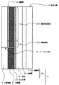
(接着力差)領域によって接着力に差をつける方法について説明する。配送伝票10は、図3に示すように、プリンタで印字できる少なくとも配達票101と貼付票103とが連設された伝票用紙11が、配達票101の部分は剥離可能な状態で、かつ、貼付票103の部分は強接着状態で、基材21、粘着層33及び剥離紙25からなるラベル用紙20の基材21の面に接着層31を介して積層され、伝票用紙11の裏面側には剥離層13が、基材21の表面側には目止め層23が設けられている。
(Adhesive strength difference) A method of making a difference in adhesive strength depending on the region will be described. As shown in FIG. 3, the
この剥離層13、接着層31、及び目止め層23の組合せによって、領域による接着力の差を設けることができる。剥離層13の面積、又はインキ量を多く印刷すると、接着力が弱くなる。目止め層23を設けると接着力が強くなり、設けないと接着力が弱くなる。但し、接着層31として感圧接着剤を用いた圧着方式の場合には、上記とは逆に作用し、目止め層を設けると接着力が弱くなり、設けないと接着力が強くなる。接着層31を形成する接着剤として接着力の強弱が異なる複数の接着剤などを使い分けたり、接着層31の塗布形状を全面のベタ状塗布や、ドット状の面積や密度の異なるドットパターンとすることで接着力を制御することができる。このように、剥離層13、接着層31、及び目止め層23の組合せによって、領域による接着力の差を設ける。接着力がハ<イの接着力の関係となればよく、接着力の絶対値としては特に限定されるものではない。 Depending on the combination of the release layer 13, the adhesive layer 31, and the sealing layer 23, a difference in adhesive force depending on the region can be provided. If the area of the release layer 13 or the amount of ink is printed, the adhesive strength is weakened. If the sealing layer 23 is provided, the adhesive force is increased, and if not provided, the adhesive force is decreased. However, in the case of a pressure-bonding method using a pressure-sensitive adhesive as the adhesive layer 31, the reverse action is exerted. When the sealing layer is provided, the adhesive force is weakened, and when not provided, the adhesive force is increased. A plurality of adhesives with different adhesive strengths are used as the adhesive for forming the adhesive layer 31, or the application shape of the adhesive layer 31 is a solid application on the entire surface, or a dot pattern having a different dot area and density. Thus, the adhesive force can be controlled. As described above, the combination of the release layer 13, the adhesive layer 31, and the sealing layer 23 provides a difference in adhesive force depending on the region. It is only necessary for the adhesive force to satisfy the relation of “H <i”, and the absolute value of the adhesive force is not particularly limited.
(従来)従来の配送伝票10は図4に示すように、全面剥離領域309に接着力の差はなく、全体的に弱いので、配送伝票10の配達票101などの剥離可能な剥離片は、製造中、プリンタでの印字中、輸送などの運用中、又は製造から運用における環境の変化でも捲れや脱落が生じ易い。このために、製造工程やプリンタでの印字作業での効率が低下する。
(Conventional) As shown in FIG. 4, the
(剥離終端領域)剥離終端領域307の形状は、図2のように、剥離開始端部71から剥離して前記配達票101を分離する際に、剥離が終わって前記配達票101が分離する辺に沿って設けられた所定幅の形状となっており、接着力をイとした、ロの字状の領域の一辺を形成している。もちろん、その辺に沿って設けられた所定幅の形状とそのロの字状の領域を併せて、剥離終端領域307としてもよい。剥離終端領域307及びロの字状の領域を除く領域を剥離領域305とする。そして、剥離終端領域307及びロの字状の領域の接着力をイとし、剥離終端領域307及びロの字状の領域(すなわち、接着力をイとした領域)を除く剥離領域305の接着力をハとしたときに、ハ<イの接着力の関係となるように設定すればよい。即ち、図3のように、剥離終端領域307及びロの字状の領域の接着力を強く、剥離領域305の接着力を弱くすればよい。
(Peeling termination region) The shape of the peeling
また、剥離終端領域307からロの字状に延設された領域が配達票101の両側面及び前記貼付票103から離間する距離は0mmより大きく、1mm程度以下、好ましくは0.8mm以下が好ましい。さらに、剥離終端領域307は配達票101の貼付票103側にずらして設けてもよく、このずらしの幅としては0mmより大きく、1mm程度以下、好ましくは0.8mm以下が好ましい。
Further, the distance-shape extending regions of Russia from the
剥離終端領域307及びロの字状の領域(すなわち、接着力をイとした領域)の接着力は、通常剥離層13を剥離終端領域307の部分だけ未塗工部を設けたり、又は部分的に未塗工部を設けたりすることで、接着力を強くする。しかしながら、剥離終端領域307及びロの字状の領域の接着力が強過ぎると、配達票101を剥離する際に配達票101が破れたり、紙剥けが生じたりするので、剥離終端領域307の所定の幅、さらには、中央部が欠落したロの字状の領域の幅としては0mmより大きく、1mm程度以下、好ましくは0.8mm以下が好ましい。例えば、前記未塗工部を直径0.3mmのドット状としたり、幅が0.5mmで長さが5mmの矩形を6mmピッチで設けたり、した場合には、プリンタで印字の際も配達票101の捲れもなく良好で、しかも、配達票101を容易に分離することができる。
The adhesive strength of the peeling
また、幅が0.8mmで長さが5mmの矩形を6mmピッチで未塗工部を設けた場合には、プリンタで印字の際は配達票101の捲れもなく良好であったが、配達票101を40℃90%RHの環境下で分離すると若干紙剥けが生じたが、25℃60%RHの環境下では紙剥けもなく、容易に分離できるので、実用上の問題は少ない。 In addition, when a rectangle having a width of 0.8 mm and a length of 5 mm was provided with an uncoated portion at a pitch of 6 mm, the delivery slip 101 was satisfactory when printed by a printer. When 101 was separated in an environment of 40 ° C. and 90% RH, some paper peeling occurred. However, in an environment of 25 ° C. and 60% RH, the paper was not peeled off and could be easily separated, so there were few practical problems.
(剥離領域)剥離領域305の接着力は、該接着力をハとする。剥離領域305は配達票101の大半の部分を占め、かつ設計通りの接着力で剥離できるように構成されている。剥離終端領域307及びロの字状の領域(すなわち、接着力をイとした領域)よりは弱く設定する。
(Peeling area) The adhesive strength of the
このようにすることで、剥離開始端部71から剥離して配達票101を分離する際には配達票101を破れずに分離し易く、しかも、配送伝票10の剥離可能な剥離片(配達票101など)でも、製造中、プリンタでの印字中、輸送などの運用中、又は製造から運用における環境の変化でも捲れや脱落が生じ難い。
In this way, when separating the delivery slip 101 by peeling from the peeling
(伝票用紙)伝票用紙11としては、充分な強度と印刷やプリンタによる印刷、印字適性及び搬送適性を有するものであれば使用でき、例えば、上質紙、NIP用紙、コート紙、アート紙、クラフト紙、複写用紙、グラシン紙、パーチメント紙、レーヨン紙、合成紙、樹脂フィルムによりラミネートされた紙等の紙が好適に用いられるが、セロファン、延伸ポリプロピレン、ポリエチレンテレフタレート、延伸ポリスチレン、ポリ塩化ビニル等の樹脂フィルムであってもよい。印字適性の点からNIP用紙が好ましい。伝票用紙11の厚さとしては、印字適性及び取扱性から、20〜200μm程度、好ましくは50〜150μmである。また、伝票用紙11へは必要に応じて、絵柄や説明文などの印刷を施してもよい。 (Slip paper) The slip paper 11 can be used as long as it has sufficient strength and printing, printer printing, printability and transportability, for example, high-quality paper, NIP paper, coated paper, art paper, craft paper. Paper such as copying paper, glassine paper, parchment paper, rayon paper, synthetic paper, paper laminated with a resin film is preferably used, but resin such as cellophane, stretched polypropylene, polyethylene terephthalate, stretched polystyrene, polyvinyl chloride, etc. It may be a film. NIP paper is preferable from the viewpoint of printability. The thickness of the slip sheet 11 is about 20 to 200 μm, preferably 50 to 150 μm, from the viewpoint of printability and handleability. Moreover, you may print a picture, an explanatory note, etc. on the slip paper 11 as needed.
(剥離層)伝票用紙11の裏面側には剥離層13を設けてもよい。伝票用紙11の所望
の分離可能になるように設ける剥離層13としては、配達票101が基材21から容易に
剥離できるような接着性の低い樹脂のフィルム又は印刷層を使用することが好ましい。例
えば、ポリエチレン、ポリプロピレン、ポリブチレン等のオレフィン系(共)重合体を用
いることが最も好ましいが、他にも、ポリスチレン、ポリビニルブチラール、酢酸ビニル
共重合体、エチレン−酢酸ビニル共重合体、塩化ビニル−酢酸ビニル共重合体、アクリル
樹脂、セルロース樹脂等の熱可塑性樹脂及びこれらの混合物からなるフィルムでもよい。
また、ポリウレタン等の熱硬化性樹脂等から形成されたフィルムを用いてもよい。また、
後述する接着層31と剥離性を持つインキを用いた印刷層でもよい。さらに、所望に応じ
て、剥離層13には酸化防止剤、熱安定剤、紫外線吸収剤、スリップ剤、帯電防止剤、防
曇剤、着色剤、フィラー等が添加されていてもよい。剥離層13を形成するための
樹脂の塗布量・塗布厚は特に限定されないが、好ましくは、塗布量は0.1〜10μm程
度、好ましくは0.5〜10μmである。
(Peeling Layer) A peeling layer 13 may be provided on the back side of the slip sheet 11. As the release layer 13 provided so that the slip sheet 11 can be separated as desired, it is preferable to use a resin film or a print layer with low adhesion so that the delivery slip 101 can be easily released from the base material 21. For example, it is most preferable to use an olefinic (co) polymer such as polyethylene, polypropylene, and polybutylene. In addition, polystyrene, polyvinyl butyral, vinyl acetate copolymer, ethylene-vinyl acetate copolymer, vinyl chloride- It may be a film made of a vinyl acetate copolymer, an acrylic resin, a thermoplastic resin such as a cellulose resin, or a mixture thereof.
Moreover, you may use the film formed from thermosetting resins, such as a polyurethane. Also,
It may be a printing layer using an ink having releasability with an adhesive layer 31 described later. Furthermore, an antioxidant, a heat stabilizer, an ultraviolet absorber, a slip agent, an antistatic agent, an antifogging agent, a colorant, a filler, and the like may be added to the release layer 13 as desired. Although the application amount and application thickness of the resin for forming the release layer 13 are not particularly limited, the application amount is preferably about 0.1 to 10 μm, preferably 0.5 to 10 μm.
(ラベル用紙)ラベル用紙20としては、基材21、粘着層33及び剥離紙25からなっている。基材21の表面側には必要に応じて目止め層23が設けられている。
(Label Paper) The
(基材)基材21としては、伝票用紙11と同様の紙やフィルムが使用できる。また、基材21の表面及び/又は裏面へは、必要に応じて、絵柄や説明文などの自由な印刷を施してもよい。 (Substrate) As the substrate 21, the same paper or film as the slip sheet 11 can be used. Moreover, you may give free printing, such as a design and an explanatory note, to the surface and / or back surface of the base material 21 as needed.
(目止め層)目止め層23としては、基材21と後述の接着層31との間に、接着層31が基材21へ浸透を防止し、伝票用紙11と基材21との接着力を調整するために、基材21面へ目止め層23を設けてもよい。目止め層23としては、所謂バインダと呼ばれる、従来公知の塩化ビニル系樹脂、アクリル系樹脂、ウレタン系樹脂、ポリエステル系樹脂、ポリアミド樹脂、セルロース誘導体などの熱可塑性樹脂、熱硬化性樹脂、反応型樹脂やこれらの混合物が使用し、必要に応じて添加剤を加えて、公知のコーティング法又は印刷法で塗布又は印刷すればよい。 (Sealing Layer) As the sealing layer 23, the adhesive layer 31 prevents penetration into the base material 21 between the base material 21 and an adhesive layer 31 described later, and the adhesive force between the slip sheet 11 and the base material 21. In order to adjust, the sealing layer 23 may be provided on the surface of the base material 21. As the sealing layer 23, a so-called binder, a conventionally known vinyl chloride resin, acrylic resin, urethane resin, polyester resin, polyamide resin, cellulose derivative, or other thermoplastic resin, thermosetting resin, reactive type, or the like is used. A resin or a mixture of these may be used, and additives may be added as necessary, and coating or printing may be performed by a known coating method or printing method.
(粘着層)粘着層33としては、荷物などに配送伝票10を貼付可能とする感圧接着剤であり、アクリル系粘着剤が最も好ましいが、天然ゴム系粘着剤、合成ゴム系粘着剤、シリコーンゴム系粘着剤等でもよい。粘着剤層33を形成するための粘着剤の塗布量・塗布厚は特に限定されないが、好ましくは、塗布量は0.1〜50g/m2で程度、好ましくは3〜30g/m2であり、塗布厚は0.1〜50μm程度、好ましくは3〜30μmである。
(Adhesive layer) The adhesive layer 33 is a pressure-sensitive adhesive that enables the
(剥離紙)剥離紙25(セパレート紙、セパ紙とも呼ばれる)としては、上質紙、コート紙、含浸紙及びプラスチックフィルムなどの基材の片面に離型層を有している。離型層としては、離型性を有する材料であれば、特に限定されないが、例えば、シリコーン樹脂、有機樹脂変性シリコーン樹脂、フッ素樹脂、アミノアルキド樹脂、ポリエステル樹脂などがある。これらの樹脂は、エマルジョン型、溶剤型又は無溶剤型のいずれもが使用できる。 (Release paper) The release paper 25 (also called a separate paper or a separate paper) has a release layer on one side of a base material such as high-quality paper, coated paper, impregnated paper, and plastic film. The release layer is not particularly limited as long as it is a material having releasability, and examples thereof include silicone resins, organic resin-modified silicone resins, fluorine resins, aminoalkyd resins, and polyester resins. These resins can be used in any of emulsion type, solvent type and solventless type.
(接着層)接着層31としては、基材21と伝票用紙11を一体化するためのものであり、例えば、ウレタン系、アクリル系、酢酸ビニール系などの熱可塑性樹脂を使用することができ、フレキソ法、グラビア法などの公知の印刷法又はコーティング法によって、厚み0.1〜50μm程度、好ましくは2〜15μmに塗布し、貼り合わせ前又は後に、必要に応じて乾燥させる。基材21と伝票用紙11とを接着剤(又は樹脂)が乾燥していない状態で貼り合わせるウェット又はセミウェットラミネート方式、熱圧着方式や感圧方式によって貼り合わせることが好ましいが、特に限定されるものではない。 (Adhesive layer) The adhesive layer 31 is for integrating the base material 21 and the slip paper 11, and for example, urethane, acrylic, vinyl acetate or other thermoplastic resins can be used, The film is applied to a thickness of about 0.1 to 50 μm, preferably 2 to 15 μm by a known printing method or coating method such as a flexo method or a gravure method, and dried as necessary before or after bonding. The substrate 21 and the slip sheet 11 are preferably bonded together by a wet or semi-wet lamination method, a thermocompression bonding method, or a pressure-sensitive method in which the adhesive (or resin) is not dried. It is not a thing.
(積層)伝票用紙11に設けられた剥離層13の部分が、図1に示すように、分離可能な配達票101となり、基材21から容易に剥離できて分離可能となる。分離後の配達票101には受領書を兼務させてもよい。 (Lamination) The part of the release layer 13 provided on the slip sheet 11 becomes a separable delivery slip 101 as shown in FIG. The delivery slip 101 after separation may also serve as a receipt.
(ハーフカット部)ハーフカット部41の加工は公知のビク刃によるハーフカット法などが適用できる。また、図5に示すように、複数のアンカット61と複数の小ハーフカット65と小ハーフカット65の剥離開始端部71側を起点とし剥離開始端部71側に傾く斜めカット63とからなるえハーフカット部41を設ける場合には、アンカット61を除いて、小ハーフカット65及び斜めカット63を加工する方法は、公知の伝票用紙11側からのハーフカット法でよいが、寸法が細かいので、エッチング刃を用いる加工方法が好ましい。
(Half-cut portion) The half-
本発明は、剥離可能な剥離片では製造中、プリンタでの印字中、輸送などの運用中、又は製造から運用における環境の変化でも捲れや脱落が生じ難い配送伝票に利用することができる。しかしながら、部分的に剥離可能な剥離片を必要とする用途であれば、特に限定されるものではない。 INDUSTRIAL APPLICABILITY The present invention can be used for a delivery slip that can be easily peeled off or not dropped during manufacturing, during printing with a printer, during operation such as transportation, or even when the environment changes from manufacturing to operation. However, the application is not particularly limited as long as the application requires a partially peelable release piece.
10:配送伝票
11:伝票用紙
13:剥離層
20:ラベル用紙
21:基材
23:目止め層
25:剥離紙
31:接着層
33:粘着層
41:ハーフカット部
53:切離部
61:アンカット
63:斜めカット
65:小ハーフカット
71:剥離開始端部
81:交点
101:配達票
103:貼付票
107:リブ部
305:剥離領域
307:剥離終端領域
309:全面剥離領域
10: Delivery slip 11: Slip paper 13: Release layer 20: Label paper 21: Base material 23: Sealing layer 25: Release paper 31: Adhesive layer 33: Adhesive layer 41: Half cut part 53: Separation part 61: Ann Cut 63: Diagonal cut 65: Small half cut 71: Peeling start end portion 81: Intersection point 101: Delivery slip 103: Adhesive slip 107: Rib portion 305: Peeling region 307: Peeling termination region 309: Whole surface peeling region
Claims (2)
前記配達票と前記貼付票との間に設けられたハーフカット部を境界にして前記配達票の剥離開始端部から剥離して前記配達票を分離でき、
前記ハーフカット部は、複数のアンカットと、複数の小ハーフカットと、前記小ハーフカットから分岐し該剥離開始端部側に傾く斜めカットと、からなり、
かつ、前記剥離開始端部から剥離して前記配達票を分離する際に、剥離が終わって前記配達票が分離する辺に沿って設けられた所定幅の剥離終端領域、ならびに前記剥離終端領域と一辺が重なるロの字状の領域であって、前記ロの字状の領域の残り三辺は前記配達票の外周から間隔を開けて設けられ、
前記剥離終端領域ならびに前記ロの字状の領域の残り三辺の領域の接着力をイとし、前記接着力をイとした領域を除く剥離領域の接着力をハとしたときに、ハ<イの接着力の関係であることを特徴とする配送伝票。 Even without low and the sticking slip and delivery form provided continuously, part of the delivery form is Te delivery form odor laminated through an adhesive layer to the substrate in a peelable state,
The delivery slip can be separated by peeling from the peeling start end of the delivery slip with a half cut portion provided between the delivery slip and the sticking slip as a boundary,
The half-cut portion comprises a plurality of uncuts, a plurality of small half-cuts, and an oblique cut that branches off from the small half-cut and tilts toward the peeling start end side,
And when separating the delivery slip by separating from the separation start end, a separation termination region having a predetermined width provided along a side where the delivery slip is separated after separation , and the separation termination region A square-shaped area with one side overlapping, and the remaining three sides of the square-shaped area are provided at intervals from the outer periphery of the delivery slip,
Wherein the peeling termination region and Lee adhesion area of the remaining three sides of the shaped area of the filtration, the adhesion of the peeled area excluding the adhesion was Lee area when the Ha, Ha <b delivery slip, characterized in that of the relationship of the adhesive force.
Priority Applications (1)
| Application Number | Priority Date | Filing Date | Title |
|---|---|---|---|
| JP2012122049A JP6089448B2 (en) | 2012-05-29 | 2012-05-29 | Delivery slip |
Applications Claiming Priority (1)
| Application Number | Priority Date | Filing Date | Title |
|---|---|---|---|
| JP2012122049A JP6089448B2 (en) | 2012-05-29 | 2012-05-29 | Delivery slip |
Publications (2)
| Publication Number | Publication Date |
|---|---|
| JP2013244718A JP2013244718A (en) | 2013-12-09 |
| JP6089448B2 true JP6089448B2 (en) | 2017-03-08 |
Family
ID=49844871
Family Applications (1)
| Application Number | Title | Priority Date | Filing Date |
|---|---|---|---|
| JP2012122049A Active JP6089448B2 (en) | 2012-05-29 | 2012-05-29 | Delivery slip |
Country Status (1)
| Country | Link |
|---|---|
| JP (1) | JP6089448B2 (en) |
Cited By (6)
| Publication number | Priority date | Publication date | Assignee | Title |
|---|---|---|---|---|
| US10459485B2 (en) | 2013-09-10 | 2019-10-29 | Flexterra, Inc. | Attachable article with signaling, split display and messaging features |
| US10621956B2 (en) | 2014-02-10 | 2020-04-14 | Flexterra, Inc. | Attachable device with flexible electronic display orientation detection |
| US10782734B2 (en) | 2015-02-26 | 2020-09-22 | Flexterra, Inc. | Attachable device having a flexible electronic component |
| US10834822B2 (en) | 2013-12-24 | 2020-11-10 | Flexterra, Inc. | Support structures for a flexible electronic component |
| US11079620B2 (en) | 2013-08-13 | 2021-08-03 | Flexterra, Inc. | Optimization of electronic display areas |
| US11086357B2 (en) | 2013-08-27 | 2021-08-10 | Flexterra, Inc. | Attachable device having a flexible electronic component |
Family Cites Families (4)
| Publication number | Priority date | Publication date | Assignee | Title |
|---|---|---|---|---|
| JPH08258458A (en) * | 1995-03-27 | 1996-10-08 | Toppan Moore Co Ltd | Delivery slip |
| JP4094717B2 (en) * | 1998-03-24 | 2008-06-04 | 大日本印刷株式会社 | Delivery slip |
| JP2003191961A (en) * | 2001-12-27 | 2003-07-09 | Dainippon Printing Co Ltd | Dp bag for photograph |
| JP2008162141A (en) * | 2006-12-28 | 2008-07-17 | Daio Paper Corp | False adhesive paper |
-
2012
- 2012-05-29 JP JP2012122049A patent/JP6089448B2/en active Active
Cited By (6)
| Publication number | Priority date | Publication date | Assignee | Title |
|---|---|---|---|---|
| US11079620B2 (en) | 2013-08-13 | 2021-08-03 | Flexterra, Inc. | Optimization of electronic display areas |
| US11086357B2 (en) | 2013-08-27 | 2021-08-10 | Flexterra, Inc. | Attachable device having a flexible electronic component |
| US10459485B2 (en) | 2013-09-10 | 2019-10-29 | Flexterra, Inc. | Attachable article with signaling, split display and messaging features |
| US10834822B2 (en) | 2013-12-24 | 2020-11-10 | Flexterra, Inc. | Support structures for a flexible electronic component |
| US10621956B2 (en) | 2014-02-10 | 2020-04-14 | Flexterra, Inc. | Attachable device with flexible electronic display orientation detection |
| US10782734B2 (en) | 2015-02-26 | 2020-09-22 | Flexterra, Inc. | Attachable device having a flexible electronic component |
Also Published As
| Publication number | Publication date |
|---|---|
| JP2013244718A (en) | 2013-12-09 |
Similar Documents
| Publication | Publication Date | Title |
|---|---|---|
| JP6089448B2 (en) | Delivery slip | |
| JP5987553B2 (en) | Delivery slip | |
| JP5962216B2 (en) | Delivery slip | |
| JP5994391B2 (en) | Delivery slip | |
| JP6040520B2 (en) | Delivery slip | |
| JP2014040005A (en) | Delivery slip | |
| JP5994386B2 (en) | Delivery slip | |
| JP5755973B2 (en) | Form printing sheet and delivery slip | |
| JP6040629B2 (en) | Delivery slip | |
| JP2007199140A (en) | Continuous label sheet | |
| JP2016153857A (en) | Label sheet | |
| JP6249065B2 (en) | Delivery slip | |
| JP5957849B2 (en) | Delivery slip | |
| JP6089449B2 (en) | Delivery slip | |
| JP6278068B2 (en) | Delivery slip | |
| JP6168094B2 (en) | Delivery slip | |
| JP6112136B2 (en) | Delivery slip | |
| JP6217814B2 (en) | Delivery slip | |
| JP6988072B2 (en) | Delivery slip | |
| JP6739791B2 (en) | Manufacturing method of information printed label | |
| JP2015231704A (en) | Delivery form | |
| JP6303319B2 (en) | Delivery slip | |
| JP5648337B2 (en) | Delivery slip | |
| JP7062435B2 (en) | label | |
| JP2017226168A (en) | Delivery slip and continuous slip sheet |
Legal Events
| Date | Code | Title | Description |
|---|---|---|---|
| A621 | Written request for application examination |
Free format text: JAPANESE INTERMEDIATE CODE: A621 Effective date: 20150422 |
|
| A131 | Notification of reasons for refusal |
Free format text: JAPANESE INTERMEDIATE CODE: A131 Effective date: 20160531 |
|
| A977 | Report on retrieval |
Free format text: JAPANESE INTERMEDIATE CODE: A971007 Effective date: 20160531 |
|
| A521 | Written amendment |
Free format text: JAPANESE INTERMEDIATE CODE: A523 Effective date: 20160728 |
|
| TRDD | Decision of grant or rejection written | ||
| A01 | Written decision to grant a patent or to grant a registration (utility model) |
Free format text: JAPANESE INTERMEDIATE CODE: A01 Effective date: 20170110 |
|
| A61 | First payment of annual fees (during grant procedure) |
Free format text: JAPANESE INTERMEDIATE CODE: A61 Effective date: 20170123 |
|
| R150 | Certificate of patent or registration of utility model |
Ref document number: 6089448 Country of ref document: JP Free format text: JAPANESE INTERMEDIATE CODE: R150 |