JP2010046953A - False adhesive label and method of manufacturing same - Google Patents
False adhesive label and method of manufacturing same Download PDFInfo
- Publication number
- JP2010046953A JP2010046953A JP2008214309A JP2008214309A JP2010046953A JP 2010046953 A JP2010046953 A JP 2010046953A JP 2008214309 A JP2008214309 A JP 2008214309A JP 2008214309 A JP2008214309 A JP 2008214309A JP 2010046953 A JP2010046953 A JP 2010046953A
- Authority
- JP
- Japan
- Prior art keywords
- pseudo
- adhesive label
- base material
- surface base
- layer
- Prior art date
- Legal status (The legal status is an assumption and is not a legal conclusion. Google has not performed a legal analysis and makes no representation as to the accuracy of the status listed.)
- Pending
Links
Images


Abstract
Description
本発明は、物品の配送や管理、各種の保険やチケットの申し込み等に使用される記録票、伝票等の用途に好適な擬似接着ラベルおよびその製造方法に関する。 The present invention relates to a pseudo-adhesive label suitable for uses such as record slips and slips used for delivery and management of goods, application for various insurances and tickets, and a manufacturing method thereof.
郵便、宅配便、通信販売などにおいて商品の受注、発送、顧客の受け取り等の工程からなる流通過程を管理するために、伝票類が用いられる。広く用いられている伝票の一つとして、感圧紙を複数枚積層させたものがある。このような伝票に商品名、送り先などの情報を書き込む際には、強い圧力を加えないと一番下の紙面まで鮮明に書き込むことができないため、ボールペン、タイプライター、ドットプリンター等が必要となる。 In order to manage a distribution process including processes such as ordering of goods, shipping, and receipt of customers in mail, courier service, mail order, etc., slips are used. One of widely used slips is a stack of a plurality of pressure sensitive papers. When writing information such as product names and destinations on such slips, a ballpoint pen, typewriter, dot printer, etc. are required because it is impossible to write clearly to the bottom of the paper unless strong pressure is applied. .
しかしながら、ボールペン、タイプライター等による書き込みは煩雑な作業であり、また時には誤字、脱字、写し間違いなどによる誤送の原因となり得る。また、ドットプリンターでは印字に時間がかかる等の欠点がある。 However, writing with a ballpoint pen, typewriter, or the like is a cumbersome task, and can sometimes cause erroneous sending due to typographical errors, omissions, or copying errors. Further, the dot printer has a drawback that printing takes time.
このような問題を解決するために、擬似接着シート、例えば、表面基材、水系エマルジョン擬似接着層、熱可塑性擬似接着層、接着剤、剥離基材で構成され、表面基材と熱可塑性擬似接着層とが擬似接着されたものを用いることが知られている(例えば特許文献1および2参照)。これらの擬似接着シートによれば、郵便、宅配便、通信販売などにおいて商品の受注から顧客の受け取りまでを一枚で管理することが可能であり、さらにレーザプリンタ、熱転写などによる情報の迅速な書き込みが可能な物流管理用シートを提供できる。
上述のようなラベルの問題点として、配送物に貼られた擬似接着ラベルから表面基材を剥がす際に、表面基材が破れ易い点が挙げられる。一般に、擬似接着ラベルは、ダイカット加工により所定の形状に打ち抜かれており、表面基材の破れは、ダイカットされた部分を起点にして生じることが多い。 As a problem of the label as described above, when the surface base material is peeled off from the pseudo-adhesive label attached to the delivery item, the surface base material is easily broken. In general, the pseudo-adhesive label is punched into a predetermined shape by die cutting, and the surface base material is often broken starting from the die-cut portion.
そこで本発明は、たとえ薄くて破れ易い紙から成る表面基材を有する擬似接着ラベルであっても、配送物等に貼られた状態で、破れを生じさせずに表面基材を引き剥がすことができる擬似接着ラベル、およびそのような擬似接着ラベルを製造する方法を提供することを目的とする。 Therefore, the present invention can peel off the surface base material without causing tearing even if it is a pseudo-adhesive label having a surface base material made of paper that is thin and easily torn. It is an object to provide a pseudo-adhesive label that can be produced and a method for producing such a pseudo-adhesive label.
本発明における擬似接着ラベルの製造方法は、表面基材、表面基材に擬似接着されている擬似接着層、及び被着物に貼着されるための粘着剤層がこの順に積層された擬似接着ラベルの製造方法である。そして、擬似接着ラベルの製造方法は、表面基材側からのレーザの照射により擬似接着ラベルを裁断する裁断工程を備えることを特徴とする。 The method for producing a pseudo-adhesive label according to the present invention includes a pseudo-adhesive label in which a surface base material, a pseudo-adhesive layer pseudo-adhered to the surface base material, and a pressure-sensitive adhesive layer to be attached to an adherend are laminated in this order. It is a manufacturing method. And the manufacturing method of a pseudo adhesive label is equipped with the cutting process of cutting a pseudo adhesive label by irradiation of the laser from the surface base material side, It is characterized by the above-mentioned.
擬似接着ラベルの製造方法においては、レーザを擬似接着ラベルに照射することにより、表面基材においてハーフカット線を形成するハーフカット線形成工程をさらに有することが好ましい。表面基材は、例えば、感熱紙、クラフト紙、上質紙、またはグラシン紙のいずれかであり、表面基材の秤量は15〜120g/m2であることが好ましい。 The method for producing a pseudo-adhesive label preferably further includes a half-cut line forming step for forming a half-cut line on the surface base material by irradiating the pseudo-adhesive label with a laser. The surface substrate is, for example, any one of thermal paper, kraft paper, high-quality paper, or glassine paper, and the weight of the surface substrate is preferably 15 to 120 g / m 2 .
本発明における擬似接着ラベルにおいては、表面基材、表面基材に擬似接着されている擬似接着層、及び被着物に貼着されるための粘着剤層がこの順に積層されており、表面基材側からのレーザの照射により裁断されていることを特徴とする。 In the pseudo-adhesive label of the present invention, the surface base material, the pseudo-adhesive layer pseudo-bonded to the surface base material, and the pressure-sensitive adhesive layer to be attached to the adherend are laminated in this order, It is characterized by being cut by laser irradiation from the side.
擬似接着ラベルにおいては、レーザを擬似接着ラベルに照射することにより、表面基材においてハーフカット線が形成されていることが好ましい。また、表面基材は、例えば、感熱紙、クラフト紙、上質紙、またはグラシン紙のいずれかであり、表面基材の秤量は15〜120g/m2であることが好ましい。 In the pseudo-adhesive label, it is preferable that a half-cut line is formed on the surface base material by irradiating the pseudo-adhesive label with a laser. The surface substrate is, for example, any one of thermal paper, kraft paper, high-quality paper, or glassine paper, and the weight of the surface substrate is preferably 15 to 120 g / m 2 .
本発明によれば、たとえ薄くて破れ易い紙から成る表面基材を有する擬似接着ラベルであっても、配送物等に貼られた状態で、破れを生じさせずに表面基材を引き剥がすことができる擬似接着ラベル、およびそのような擬似接着ラベルを製造する方法を提供できる。 According to the present invention, even if it is a pseudo-adhesive label having a surface base material made of paper that is thin and easily torn, the surface base material is peeled off without causing tearing in a state of being stuck on a delivery item or the like. A pseudo-adhesive label that can be manufactured and a method of manufacturing such a pseudo-adhesive label can be provided.
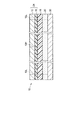
本発明における擬似接着ラベルの実施形態につき説明する。図1は、剥離紙上に設けられた擬似接着ラベルを示す断面図である。図2は、剥離紙上に設けられた擬似接着ラベルを示す平面図である。 An embodiment of a pseudo-adhesive label according to the present invention will be described. FIG. 1 is a cross-sectional view showing a pseudo-adhesive label provided on a release paper. FIG. 2 is a plan view showing the pseudo-adhesive label provided on the release paper.
擬似接着ラベル10は、剥離紙30の上に設けられる。擬似接着ラベル10は、表面基材12、剥離制御層16、熱可塑性樹脂層18(擬似接着層)、および粘着剤層20を含む。これらの層は、この順に積層されており、剥離紙30から最も離れた表面側に表面基材12、剥離紙30のすぐ上側に粘着剤層20が設けられている。熱可塑性樹脂層18は、剥離制御層16を介して表面基材12に擬似接着されている。
The pseudo
擬似接着ラベル10の外郭形状は、裁断線10Lによって定められる。例えば、本実施形態の擬似接着ラベル10は矩形状である(図2参照)。そして、剥離紙30上に積層された擬似接着ラベル10の周辺部分、すなわち裁断線10Lの外側の領域はラベルとして使用されない。
The outline shape of the
擬似接着ラベル10の中央には、ハーフカット線10Hが設けられている。そして、擬似接着ラベル10の使用時には、まず、粘着剤層20が剥離紙30から剥がされ、配送物等の被着物に貼着される。この状態で、剥離制御層16より上側の表面基材12と剥離制御層16とから成る上部シート24を、熱可塑性樹脂層18から剥離させることができる。そして、上部シート24の剥離により露出した剥離制御層16と熱可塑性樹脂層18の表面には、もはや粘着性が無いため、剥離後のシート同士を重ねても互いに接着することは無い。上部シート24は、ハーフカット線10Hを境にして左右の矩形ラベル21および22(図2参照)に分離して剥離可能である。以下、擬似接着ラベル10の各層につき説明する。
A half-
表面基材12:擬似接着ラベル10の表面を形成する。一般的には、感熱紙、クラフト紙、上質紙、グラシン紙、パーチメント紙、レーヨン紙、コート紙などの紙が用いられる。そして表面基材12の秤量は、15〜120g/m2、好ましくは、20〜100g/m2である。
Surface substrate 12: forms the surface of the
剥離制御層16:表面基材12と熱可塑性樹脂層18とが互いに接着されてしまうことを防止し、上部シート24を剥離可能にするために用いられる。剥離制御層16の材質としては、例えば、スチレン−アクリル共重合体、ポリスチレン、スチレン−ブタジエン共重合体、エチレン−酢酸ビニル共重合体、アクリル酸エステル、アクリル酸エステル共重合体、エチレン−アクリル酸共重合体などが用いられる。なお、表面基材12が単体で熱可塑性樹脂層18から容易に剥離可能である場合、剥離制御層16を設けなくても良い。
Peel control layer 16: used to prevent the
熱可塑性樹脂層18:例えば、低密度ポリエチレン(LDPE、密度:0.910g/cm3以上0.930g/cm3未満)、中密度ポリエチレン(MDPE、密度:0.930g/cm3以上0.942g/cm3未満)、高密度ポリエチレン(HDPE、密度:0.942g/cm3以上)などのポリエチレン、ポリプロピレン、ポリメチルペンテンなどの熱可塑性樹脂を、単独、または複数混合して形成される。これらの中でも、擬似接着力の制御が容易である点で、熱可塑性樹脂層18に低密度ポリエチレンが含まれていることが特に好ましい。
Thermoplastic resin layer 18: For example, low density polyethylene (LDPE, density: 0.910 g / cm 3 or more and less than 0.930 g / cm 3 ), medium density polyethylene (MDPE, density: 0.930 g / cm 3 or more, 0.942 g) / Cm 3 ), polyethylene such as high density polyethylene (HDPE, density: 0.942 g / cm 3 or more), and thermoplastic resins such as polypropylene and polymethylpentene are used alone or in combination. Among these, it is particularly preferable that the
ただし、熱可塑性樹脂層18の材質は、これらには限られない。適度な強度を有する等、熱可塑性樹脂層18として必要な性能を確保できる限り、熱可塑性樹脂層18は、熱可塑性樹脂以外のもので形成されても良い。また、熱可塑性樹脂層18の厚さは、例えば、10〜50μmであり、好ましくは15〜40μmである。
However, the material of the
粘着剤層20:擬似接着ラベル10を配送物などの被着体に貼付するために用いられる。粘着剤層20は、例えば、アクリル系粘着剤、天然ゴム粘着剤、合成ゴム粘着剤、シリコーン系粘着剤などにより形成される。粘着剤層20の厚さは、特に限定されないものの、例えば20〜200μm、好ましくは40〜100μm程度である。
Adhesive layer 20: Used to attach the
次に、本実施形態の擬似接着ラベル10の製造方法につき説明する。擬似接着ラベル10の製造時には、上述の各層が積層される。そして積層工程の後に、表面基材12側からレーザを照射することにより、裁断線10L(図1および2参照)を形成する。このように、レーザの照射により擬似接着ラベル10の外郭を裁断する裁断工程により、後述するように、各層の変形を抑えつつ、剥離紙30まで確実に到達する裁断線10Lを形成できる。
Next, the manufacturing method of the pseudo
また、ハーフカット線10Hも、表面基材12側からのレーザ照射によって形成できる。レーザによるハーフカット線形成工程では、ハーフカット線10Hを、表面基材12および剥離制御層16、あるいは剥離制御層16が設けられていない場合には表面基材12のみにおいて形成することが必要とされる(図1参照)。このため、裁断工程に比べて、エネルギー量の少ないレーザ光が使用され、ハーフカット線10Hが熱可塑性樹脂層18まで到達することが防止される。
The
次に、擬似接着ラベルの評価、試験方法およびその結果につき説明する。擬似接着ラベル10の評価は、以下の実施例および比較例について行った。
Next, evaluation, test methods, and results of the pseudo adhesive label will be described. Evaluation of the
(実施例)
表面基材12(図1参照)としてのサーマル紙(日本製紙(株)製:TP60KJ−R(秤量65g/m2))に、アクリル系エマルジョン樹脂(三井化学(株)製:ボンロンS−1318)を乾燥後の塗布量が4.0g/m2となるように塗布、乾燥させ、剥離制御層16を形成した。この剥離制御層16の表面基材12とは反対側の表面に、熱可塑性樹脂層18としての低密度ポリエチレン(住友化学(株)製:スミカセンL−405H)を、厚さが20μmとなるようにTダイから押し出し、剥離制御層16にラミネートした。
(Example)
Thermal paper (manufactured by Nippon Paper Industries Co., Ltd .: TP60KJ-R (weighing 65 g / m 2 )) as surface substrate 12 (see FIG. 1), acrylic emulsion resin (manufactured by Mitsui Chemicals, Inc .: Bonlon S-1318) ) Was applied and dried so that the coating amount after drying was 4.0 g / m 2 , thereby forming a
次に、剥離紙30としての剥離シート(リンテック(株)製:8Kアオ)の剥離層上に、エマルジョン系アクリル型粘着剤(リンテック(株)製:SG)を乾燥厚が20μmとなるように加え、粘着剤層20を形成した。そして、熱可塑性樹脂層18に粘着剤層20が積層するように貼り合わせた。さらに、炭酸ガスレーザの照射による熱処理で、図2に示されたように裁断線10Lおよびハーフカット線10Hを形成し、実施例の擬似接着ラベル10を作成した。このとき、照射される炭酸ガスレーザの強度は、裁断線10Lおよびハーフカット線10Hのいずれを形成するかに応じて、調整される。
Next, an emulsion-based acrylic pressure-sensitive adhesive (manufactured by Lintec Co., Ltd .: SG) is dried on the release layer of a release sheet (manufactured by Lintec Co., Ltd .: 8K Ao) as the
(比較例)
実施例における炭酸ガスレーザの照射の代わりに、凸状押切刃を回転駆動ローラの表面に設けたダイカッターを用いてダイカット加工を行うことにより、比較例の擬似接着ラベル10’を作成した。
(Comparative example)
A
こうして得られた実施例の擬似接着ラベル10および比較例の擬似接着ラベル10“を10枚ずつ同じ種類の被着物に貼着した。そして、表面基材12および比較例の表面基材12’を、ハーフカット線10H(図1および2参照)の端部から引き剥がした。この剥離試験の結果、実施例の擬似接着ラベル10においては、10枚の表面基材12がいずれも破れることなく、剥離することができた。これに対し、比較例の擬似接着ラベル10’においては、10枚中8枚の表面基材12’が破れてしまった。
Ten
以上の結果より、実施例の擬似接着ラベル10においては、表面基材12の剥離性能が、比較例よりも優れていることが明らかである。この理由につき、以下に説明する。
From the above results, it is clear that in the
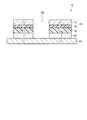
図3は、実施例の擬似接着ラベル10における裁断線10Lの近傍を拡大して示す断面図である。図4は、比較例の擬似接着ラベル10’における裁断線10Lの近傍を拡大して示す断面図である。
FIG. 3 is an enlarged cross-sectional view showing the vicinity of the
本実施形態では、レーザの照射により、擬似接着ラベル10を形成する各層を確実に切断できる。さらに、切断された領域を除くと、各層部材をほとんど変形させることなしに、剥離紙30の上面に到達する裁断線10Lを形成できる。
In the present embodiment, each layer forming the
これに対し、ダイカッターによるダイカット加工で裁断線10Lが形成された比較例の擬似接着ラベル10’(図4参照)においては、加工時の圧力により各層部材が裁断線10Lの周囲で変形し、接する層部材同士が圧着してしまう可能性もある。さらに、裁断線10Lの底では、裁断線10Lの幅が小さくなるため、最も下側の粘着剤層20’等は、完全に切断されないおそれもある。また、上記のような工程を連続して多数回に渡り繰り返すと、凸状押切刃の切れが悪くなり、上記の不具合等をより一層生じ易くなる。
On the other hand, in the
このように、各層部材が完全に切断されていない比較例の擬似接着ラベル10’においては、表面基材12’を含む上部シート24’を剥離させると、表面基材12’が、裁断線10Lを介した反対側の領域に引っ張られてしまう。このため、特に薄い表面基材12’は剥離時に破れ易くなる。
As described above, in the
一方、各層部材が裁断線10Lにより完全に切断されている実施例の擬似接着ラベル10(図3参照)においては、表面基材12を含む上部シート24の剥離を妨げる力は働かないため、表面基材12は破れにくい。
On the other hand, in the pseudo-adhesive label 10 (see FIG. 3) of the embodiment in which each layer member is completely cut by the
なお、ハーフカット線10Hについても裁断線10Lと同様であり、レーザ照射によって形成された場合、ダイカット加工により形成された場合に比べ、剥離時の表面基材12の破損を防止できる。
The half-
以上のように本実施形態においては、薄くて破れ易い紙から成る表面基材12を含む擬似接着ラベル10においても、配送物等の被着物に貼られた状態で剥離される表面基材12が破れることを確実に防止できる。さらに、ダイカット加工により裁断線10L等を形成する場合、押切刃の摩耗等により裁断条件の調整が必要となるのに対し、レーザ光の照射によりこれらを形成する本実施形態では、一度定められたレーザの出力強度等の裁断条件を変更する必要がないことから、効率的な擬似接着ラベル10の製造が可能である。
As described above, in the present embodiment, even in the
擬似接着ラベル10の構造や材質は、上述の実施形態に限定されない。例えば、本実施形態では、表面基材12、剥離制御層16、熱可塑性樹脂層18、粘着剤層20以外の層部材をさらに積層させても良い。
The structure and material of the
10 擬似接着ラベル
10H ハーフカット線
10L 裁断線
12 表面基材
16 剥離制御層
18 熱可塑性樹脂層(擬似接着層)
20 粘着剤層
10
20 Adhesive layer
Claims (6)
Priority Applications (1)
| Application Number | Priority Date | Filing Date | Title |
|---|---|---|---|
| JP2008214309A JP2010046953A (en) | 2008-08-22 | 2008-08-22 | False adhesive label and method of manufacturing same |
Applications Claiming Priority (1)
| Application Number | Priority Date | Filing Date | Title |
|---|---|---|---|
| JP2008214309A JP2010046953A (en) | 2008-08-22 | 2008-08-22 | False adhesive label and method of manufacturing same |
Publications (1)
| Publication Number | Publication Date |
|---|---|
| JP2010046953A true JP2010046953A (en) | 2010-03-04 |
Family
ID=42064458
Family Applications (1)
| Application Number | Title | Priority Date | Filing Date |
|---|---|---|---|
| JP2008214309A Pending JP2010046953A (en) | 2008-08-22 | 2008-08-22 | False adhesive label and method of manufacturing same |
Country Status (1)
| Country | Link |
|---|---|
| JP (1) | JP2010046953A (en) |
Cited By (4)
| Publication number | Priority date | Publication date | Assignee | Title |
|---|---|---|---|---|
| JP2013006289A (en) * | 2011-06-22 | 2013-01-10 | Dainippon Printing Co Ltd | Contact-bonding sheet, and method for production thereof |
| JP2013035029A (en) * | 2011-08-08 | 2013-02-21 | Dainippon Printing Co Ltd | Laser beam machining apparatus, laser beam machining method, and machining-object paper sheet |
| JP2018169532A (en) * | 2017-03-30 | 2018-11-01 | リンテック株式会社 | Pseudo adhesive label |
| JP2020166105A (en) * | 2019-03-29 | 2020-10-08 | リンテック株式会社 | Pseudo adhesive sheet for shelf label |
-
2008
- 2008-08-22 JP JP2008214309A patent/JP2010046953A/en active Pending
Cited By (5)
| Publication number | Priority date | Publication date | Assignee | Title |
|---|---|---|---|---|
| JP2013006289A (en) * | 2011-06-22 | 2013-01-10 | Dainippon Printing Co Ltd | Contact-bonding sheet, and method for production thereof |
| JP2013035029A (en) * | 2011-08-08 | 2013-02-21 | Dainippon Printing Co Ltd | Laser beam machining apparatus, laser beam machining method, and machining-object paper sheet |
| JP2018169532A (en) * | 2017-03-30 | 2018-11-01 | リンテック株式会社 | Pseudo adhesive label |
| JP2020166105A (en) * | 2019-03-29 | 2020-10-08 | リンテック株式会社 | Pseudo adhesive sheet for shelf label |
| JP7325208B2 (en) | 2019-03-29 | 2023-08-14 | リンテック株式会社 | Pseudo-adhesive sheet for shelf labels |
Similar Documents
| Publication | Publication Date | Title |
|---|---|---|
| JP2008162141A (en) | False adhesive paper | |
| JP5149096B2 (en) | Pseudo adhesive label | |
| JP4859819B2 (en) | Information recording adhesive sheet | |
| JP2010131869A (en) | Self-adhesive sheet for recording information | |
| JP2010046953A (en) | False adhesive label and method of manufacturing same | |
| JP2013244718A (en) | Delivery slip | |
| JPH07134554A (en) | Sheet for managing physical distribution and method for managing physical distribution by using the sheet | |
| JP2014040005A (en) | Delivery slip | |
| JP2013094974A (en) | Delivery slip | |
| JP5426914B2 (en) | Pseudo adhesive label | |
| JP5259302B2 (en) | Method for producing pseudo-adhesive label | |
| JP2016153857A (en) | Label sheet | |
| JP2010149471A (en) | Sheet for slip | |
| JP4558688B2 (en) | Information recording adhesive sheet | |
| JP5064327B2 (en) | Pseudo adhesive label | |
| JP6331734B2 (en) | Delivery slip | |
| JP5570291B2 (en) | label | |
| JP6765285B2 (en) | Laminated label | |
| JP2008149590A (en) | Seal for delivery | |
| JP5648337B2 (en) | Delivery slip | |
| JP2017226168A (en) | Delivery slip and continuous slip sheet | |
| WO2002072342A1 (en) | Laminate sheet and card preparing sheet | |
| JP6287460B2 (en) | Delivery slip with label | |
| JP2012194532A (en) | Pseudo adhesive label | |
| JP3178210U (en) | Delivery slip |