JP2012190868A - Two-fluid nozzle, substrate liquid processing device, substrate liquid processing method, and computer readable recording medium, in which substrate liquid processing program is recorded - Google Patents
Two-fluid nozzle, substrate liquid processing device, substrate liquid processing method, and computer readable recording medium, in which substrate liquid processing program is recorded Download PDFInfo
- Publication number
- JP2012190868A JP2012190868A JP2011050958A JP2011050958A JP2012190868A JP 2012190868 A JP2012190868 A JP 2012190868A JP 2011050958 A JP2011050958 A JP 2011050958A JP 2011050958 A JP2011050958 A JP 2011050958A JP 2012190868 A JP2012190868 A JP 2012190868A
- Authority
- JP
- Japan
- Prior art keywords
- liquid
- substrate
- discharge port
- gas
- liquid processing
- Prior art date
- Legal status (The legal status is an assumption and is not a legal conclusion. Google has not performed a legal analysis and makes no representation as to the accuracy of the status listed.)
- Granted
Links
Images

Classifications
-
- H—ELECTRICITY
- H10—SEMICONDUCTOR DEVICES; ELECTRIC SOLID-STATE DEVICES NOT OTHERWISE PROVIDED FOR
- H10P—GENERIC PROCESSES OR APPARATUS FOR THE MANUFACTURE OR TREATMENT OF DEVICES COVERED BY CLASS H10
- H10P50/00—Etching of wafers, substrates or parts of devices
-
- H—ELECTRICITY
- H10—SEMICONDUCTOR DEVICES; ELECTRIC SOLID-STATE DEVICES NOT OTHERWISE PROVIDED FOR
- H10P—GENERIC PROCESSES OR APPARATUS FOR THE MANUFACTURE OR TREATMENT OF DEVICES COVERED BY CLASS H10
- H10P72/00—Handling or holding of wafers, substrates or devices during manufacture or treatment thereof
- H10P72/04—Apparatus for manufacture or treatment
- H10P72/0402—Apparatus for fluid treatment
- H10P72/0406—Apparatus for fluid treatment for cleaning followed by drying, rinsing, stripping, blasting or the like
- H10P72/0411—Apparatus for fluid treatment for cleaning followed by drying, rinsing, stripping, blasting or the like for wet cleaning or washing
- H10P72/0414—Apparatus for fluid treatment for cleaning followed by drying, rinsing, stripping, blasting or the like for wet cleaning or washing using mainly spraying means, e.g. nozzles
-
- B—PERFORMING OPERATIONS; TRANSPORTING
- B05—SPRAYING OR ATOMISING IN GENERAL; APPLYING FLUENT MATERIALS TO SURFACES, IN GENERAL
- B05B—SPRAYING APPARATUS; ATOMISING APPARATUS; NOZZLES
- B05B7/00—Spraying apparatus for discharge of liquids or other fluent materials from two or more sources, e.g. of liquid and air, of powder and gas
- B05B7/02—Spray pistols; Apparatus for discharge
- B05B7/06—Spray pistols; Apparatus for discharge with at least one outlet orifice surrounding another approximately in the same plane
- B05B7/061—Spray pistols; Apparatus for discharge with at least one outlet orifice surrounding another approximately in the same plane with several liquid outlets discharging one or several liquids
-
- B—PERFORMING OPERATIONS; TRANSPORTING
- B05—SPRAYING OR ATOMISING IN GENERAL; APPLYING FLUENT MATERIALS TO SURFACES, IN GENERAL
- B05B—SPRAYING APPARATUS; ATOMISING APPARATUS; NOZZLES
- B05B7/00—Spraying apparatus for discharge of liquids or other fluent materials from two or more sources, e.g. of liquid and air, of powder and gas
- B05B7/02—Spray pistols; Apparatus for discharge
- B05B7/08—Spray pistols; Apparatus for discharge with separate outlet orifices, e.g. to form parallel jets, i.e. the axis of the jets being parallel, to form intersecting jets, i.e. the axis of the jets converging but not necessarily intersecting at a point
- B05B7/0807—Spray pistols; Apparatus for discharge with separate outlet orifices, e.g. to form parallel jets, i.e. the axis of the jets being parallel, to form intersecting jets, i.e. the axis of the jets converging but not necessarily intersecting at a point to form intersecting jets
- B05B7/0853—Spray pistols; Apparatus for discharge with separate outlet orifices, e.g. to form parallel jets, i.e. the axis of the jets being parallel, to form intersecting jets, i.e. the axis of the jets converging but not necessarily intersecting at a point to form intersecting jets with one single gas jet and several jets constituted by a liquid or a mixture containing a liquid
-
- B—PERFORMING OPERATIONS; TRANSPORTING
- B05—SPRAYING OR ATOMISING IN GENERAL; APPLYING FLUENT MATERIALS TO SURFACES, IN GENERAL
- B05B—SPRAYING APPARATUS; ATOMISING APPARATUS; NOZZLES
- B05B7/00—Spraying apparatus for discharge of liquids or other fluent materials from two or more sources, e.g. of liquid and air, of powder and gas
- B05B7/02—Spray pistols; Apparatus for discharge
- B05B7/08—Spray pistols; Apparatus for discharge with separate outlet orifices, e.g. to form parallel jets, i.e. the axis of the jets being parallel, to form intersecting jets, i.e. the axis of the jets converging but not necessarily intersecting at a point
- B05B7/0892—Spray pistols; Apparatus for discharge with separate outlet orifices, e.g. to form parallel jets, i.e. the axis of the jets being parallel, to form intersecting jets, i.e. the axis of the jets converging but not necessarily intersecting at a point the outlet orifices for jets constituted by a liquid or a mixture containing a liquid being disposed on a circle
-
- B—PERFORMING OPERATIONS; TRANSPORTING
- B05—SPRAYING OR ATOMISING IN GENERAL; APPLYING FLUENT MATERIALS TO SURFACES, IN GENERAL
- B05B—SPRAYING APPARATUS; ATOMISING APPARATUS; NOZZLES
- B05B7/00—Spraying apparatus for discharge of liquids or other fluent materials from two or more sources, e.g. of liquid and air, of powder and gas
- B05B7/02—Spray pistols; Apparatus for discharge
- B05B7/10—Spray pistols; Apparatus for discharge producing a swirling discharge
Landscapes
- Cleaning Or Drying Semiconductors (AREA)
- Nozzles (AREA)
- Coating Apparatus (AREA)
- Weting (AREA)
- Exposure Of Semiconductors, Excluding Electron Or Ion Beam Exposure (AREA)
Abstract
【課題】基板の表面にダメージを与えることなく良好に液処理することができる2流体ノズルや同2流体ノズルを用いた基板液処理装置及び基板液処理方法並びに基板液処理プログラムを提供すること。
【解決手段】本発明では、第1の液体を吐出する第1の液体吐出口(45)と、気体を吐出する気体吐出口(47)とを有し、第1の液体吐出口(45)から吐出した第1の液体と気体吐出口(47)から吐出した気体とを外部で混合して被処理体(基板2)に向けて混合流体(52)を噴霧する2流体ノズル(34)において、被処理体(基板2)に噴霧された混合流体(52)の被処理体上での外縁部に第2の液体を供給するための第2の液体吐出口(53)を有することにした。
【選択図】図3The present invention provides a two-fluid nozzle that can satisfactorily perform liquid processing without damaging the surface of the substrate, a substrate liquid processing apparatus, a substrate liquid processing method, and a substrate liquid processing program using the two-fluid nozzle.
In the present invention, a first liquid discharge port (45) having a first liquid discharge port (45) for discharging a first liquid and a gas discharge port (47) for discharging a gas is provided. In the two-fluid nozzle (34) for spraying the mixed fluid (52) toward the object to be processed (substrate 2) by externally mixing the first liquid discharged from the gas and the gas discharged from the gas discharge port (47) The second liquid discharge port (53) for supplying the second liquid to the outer edge portion of the mixed fluid (52) sprayed on the target object (substrate 2) on the target object is provided. .
[Selection] Figure 3
Description
本発明は、吐出した液体と気体とを外部で混合して被処理体(基板)に向けて噴霧する2流体ノズル、及び、同2流体ノズルを有する基板液処理装置、及び、同2流体ノズルを用いた基板液処理方法、並びに、同2流体ノズルを用いた基板液処理プログラムを記録したコンピュータ読み取り可能な記録媒体に関するものである。 The present invention relates to a two-fluid nozzle that mixes ejected liquid and gas externally and sprays it toward an object to be processed (substrate), a substrate liquid processing apparatus having the two-fluid nozzle, and the two-fluid nozzle. And a computer-readable recording medium on which a substrate liquid processing program using the two-fluid nozzle is recorded.
従来より、半導体部品やフラットパネルディスプレイなどを製造する場合には、半導体ウエハや液晶用基板などの基板に対して基板液処理装置を用いて洗浄液で洗浄処理した後に基板を乾燥させる乾燥処理を行っている。 Conventionally, when manufacturing semiconductor parts, flat panel displays, etc., a substrate such as a semiconductor wafer or a liquid crystal substrate is subjected to a drying process in which a substrate is processed with a cleaning liquid and then dried. ing.
そして、基板液処理装置では、基板の表面に洗浄液を噴霧して基板の表面を良好に洗浄するために、2流体ノズルを用いて基板に洗浄液と噴射ガスとを混合させた混合流体を噴霧して基板の表面を洗浄するようにしている。 In the substrate liquid processing apparatus, in order to spray the cleaning liquid onto the surface of the substrate and clean the surface of the substrate satisfactorily, a mixed fluid obtained by mixing the cleaning liquid and the jet gas is sprayed onto the substrate using a two-fluid nozzle. The surface of the substrate is cleaned.
この2流体ノズルは、洗浄液を吐出するための液体吐出口と、噴射ガスを吐出するための気体吐出口とを形成し、液体吐出口から吐出した洗浄液と気体吐出口から吐出した噴射ガスとを2流体ノズルの外部で混合し、霧状の混合流体を基板の表面に噴霧するように構成している(たとえば、特許文献1参照。)。 The two-fluid nozzle forms a liquid discharge port for discharging the cleaning liquid and a gas discharge port for discharging the injection gas, and has the cleaning liquid discharged from the liquid discharge port and the injection gas discharged from the gas discharge port. It mixes in the exterior of a 2 fluid nozzle, and it is comprised so that the mist-like mixed fluid may be sprayed on the surface of a board | substrate (for example, refer patent document 1).
ところが、上記従来の2流体ノズルでは、基板に霧状の混合流体を噴霧することで基板の表面に洗浄液の液膜が形成されるものの、基板に噴霧される混合流体の外縁部において噴射ガスの吐出圧力が高く、混合流体が噴霧される基板の表面部分の液膜の膜厚が薄くなっていた。 However, in the conventional two-fluid nozzle, although a liquid film of the cleaning liquid is formed on the surface of the substrate by spraying the mist-like mixed fluid onto the substrate, the injection gas is injected at the outer edge of the mixed fluid sprayed onto the substrate. The discharge pressure was high, and the film thickness of the liquid film on the surface portion of the substrate on which the mixed fluid was sprayed was thin.
そのため、従来の2流体ノズルを用いた基板の液処理においては、混合流体が噴霧される基板の表面部分において噴射ガスの吐出圧力の作用で基板の表面に形成した回路パターンなどが倒壊する等のダメージを受けてしまうおそれがあった。 Therefore, in the conventional liquid processing of the substrate using the two-fluid nozzle, the circuit pattern formed on the surface of the substrate collapses due to the action of the discharge pressure of the jet gas at the surface portion of the substrate where the mixed fluid is sprayed. There was a risk of taking damage.
そこで、本発明では、第1の液体を吐出する第1の液体吐出口と、気体を吐出する気体吐出口とを有し、前記第1の液体吐出口から吐出した前記第1の液体と前記気体吐出口から吐出した前記気体とを外部で混合して被処理体に向けて混合流体を噴霧する2流体ノズルにおいて、前記被処理体に噴霧された混合流体の被処理体上での外縁部に第2の液体を供給するための第2の液体吐出口を有することにした。 Therefore, in the present invention, the first liquid discharge port that discharges the first liquid and the gas discharge port that discharges the gas, the first liquid discharged from the first liquid discharge port, In the two-fluid nozzle that mixes the gas discharged from the gas discharge port outside and sprays the mixed fluid toward the object to be processed, an outer edge portion of the mixed fluid sprayed on the object to be processed on the object to be processed The second liquid discharge port for supplying the second liquid is provided.
また、前記第2の液体吐出口は、前記被処理体に噴霧された混合流体の被処理体上での外縁部又は外縁部よりも内側に向けて前記第2の液体を吐出することにした。 In addition, the second liquid discharge port discharges the second liquid toward the inner side of the outer edge portion or the outer edge portion of the mixed fluid sprayed on the target object on the target object. .
また、前記第1の液体吐出口に接続した第1の液体供給流路と前記第2の液体吐出口に接続した第2の液体供給流路とを別個に設け、前記第1及び第2の液体供給流路に流量調整器をそれぞれ設けることにした。 In addition, a first liquid supply channel connected to the first liquid discharge port and a second liquid supply channel connected to the second liquid discharge port are separately provided, and the first and second liquid supply channels are provided separately. A flow rate regulator was provided in each liquid supply channel.
また、本発明では、第1の液体を吐出する第1の液体吐出口と、気体を吐出する気体吐出口とを有する2流体ノズルを用いて、前記第1の液体吐出口から吐出した前記第1の液体と前記気体吐出口から吐出した前記気体とを外部で混合して基板に向けて混合流体を噴霧することで基板の液処理を行う基板液処理装置において、前記2流体ノズルは、前記基板に噴霧された混合流体の基板上での外縁部に第2の液体を供給するための第2の液体吐出口を有することにした。 In the present invention, the first fluid discharge port that discharges the first liquid and the two-fluid nozzle having the gas discharge port that discharges the gas are used to discharge the first liquid discharged from the first liquid discharge port. In the substrate liquid processing apparatus that performs liquid processing of a substrate by externally mixing the liquid of 1 and the gas discharged from the gas discharge port and spraying the mixed fluid toward the substrate, the two-fluid nozzle includes The second liquid discharge port for supplying the second liquid to the outer edge portion of the mixed fluid sprayed on the substrate on the substrate is provided.
また、前記2流体ノズルは、前記基板に噴霧された混合流体の基板上での外縁部又は外縁部よりも内側に向けて前記第2の液体を前記第2の液体吐出口から吐出することにした。 Further, the two-fluid nozzle discharges the second liquid from the second liquid discharge port toward the inner side of the outer edge portion or the outer edge portion of the mixed fluid sprayed on the substrate on the substrate. did.
また、前記2流体ノズルは、前記第1の液体吐出口に接続した第1の液体供給流路と前記第2の液体吐出口に接続した第2の液体供給流路とを別個に設け、前記第1及び第2の液体供給流路に流量調整器をそれぞれ設けることにした。 In addition, the two-fluid nozzle separately provides a first liquid supply channel connected to the first liquid discharge port and a second liquid supply channel connected to the second liquid discharge port, The flow rate regulators are provided in the first and second liquid supply channels, respectively.
また、前記第2の液体吐出口から前記第2の液体を吐出した後に前記第1の液体吐出口及び気体吐出口から前記第1の液体及び気体を吐出することにした。 In addition, after the second liquid is discharged from the second liquid discharge port, the first liquid and gas are discharged from the first liquid discharge port and the gas discharge port.
また、前記第2の液体を前記混合流体の流れを乱さない流速で吐出することにした。 Further, the second liquid is discharged at a flow rate that does not disturb the flow of the mixed fluid.
また、第1の液体と気体とを吐出して外部で混合する2流体ノズルを用いて基板に向けて混合流体を噴霧することで基板の液処理を行う基板液処理方法において、前記基板に噴霧された混合流体の基板上での外縁部に第2の液体を供給しながら前記基板の液処理を行うことにした。 Further, in a substrate liquid processing method for performing liquid processing on a substrate by spraying a mixed fluid toward the substrate using a two-fluid nozzle that discharges the first liquid and gas and mixes them externally, the substrate is sprayed. The substrate was subjected to the liquid treatment while supplying the second liquid to the outer edge of the mixed fluid on the substrate.
また、前記基板に噴霧された混合流体の基板上での外縁部又は外縁部よりも内側に向けて前記第2の液体を吐出することにした。 Further, the second liquid is ejected toward the inner side of the outer edge portion or the outer edge portion of the mixed fluid sprayed on the substrate.
また、前記基板に前記第2の液体を吐出した後に前記第1の液体及び気体を吐出して混合流体を噴霧することにした。 In addition, after the second liquid is discharged onto the substrate, the first liquid and gas are discharged to spray the mixed fluid.
また、前記第1の液体と前記第2の液体とをそれぞれ別個に流量調整して吐出することにした。 Further, the first liquid and the second liquid are separately discharged with their flow rates adjusted.
また、前記第2の液体を前記混合流体の流れを乱さない流速で吐出することにした。 Further, the second liquid is discharged at a flow rate that does not disturb the flow of the mixed fluid.
また、本発明では、第1の液体と気体とを吐出して外部で混合する2流体ノズルを用いて基板に向けて混合流体を噴霧することで基板の液処理を行うための基板液処理プログラムを記録したコンピュータ読み取り可能な記録媒体において、前記基板に噴霧された混合流体の基板上での外縁部に第2の液体を供給しながら前記基板の液処理を行うことにした。 Further, in the present invention, a substrate liquid processing program for performing liquid processing on a substrate by spraying a mixed fluid toward the substrate using a two-fluid nozzle that discharges the first liquid and gas and mixes them externally. In the computer-readable recording medium on which the substrate is recorded, the substrate is subjected to the liquid treatment while supplying the second liquid to the outer edge portion of the mixed fluid sprayed on the substrate on the substrate.
本発明では、被処理体(基板)に噴霧された混合流体の被処理体上(基板上)での外縁部に第2の液体を供給することで、被処理体に噴霧された混合流体の被処理体上(基板上)での外縁部において液膜が薄膜化してしまうのを防止して、被処理体の表面が受けるダメージを防止することができる。 In the present invention, by supplying the second liquid to the outer edge of the mixed fluid sprayed on the target object (substrate) on the target object (on the substrate), the mixed fluid sprayed on the target object It is possible to prevent the liquid film from being thinned at the outer edge portion on the object to be processed (on the substrate) and to prevent damage to the surface of the object to be processed.
以下に、本発明に係る2流体ノズル、同2流体ノズルを有する基板液処理装置、及び、同2流体ノズルを用いた基板液処理方法並びに基板液処理プログラムの具体的な構成について図面を参照しながら説明する。 Referring to the drawings, specific configurations of a two-fluid nozzle, a substrate liquid processing apparatus having the two-fluid nozzle, a substrate liquid processing method using the two-fluid nozzle, and a substrate liquid processing program will be described below. While explaining.
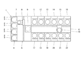
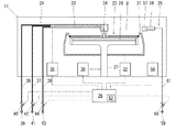
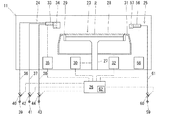
図1に示すように、基板液処理装置1は、前端部に被処理体としての基板2(ここでは、半導体ウエハ。)を複数枚(たとえば、25枚。)まとめてキャリア3で搬入及び搬出するための基板搬入出部4を形成するとともに、基板搬入出部4の後部にキャリア3に収容された基板2を搬送するための基板搬送部5を形成し、基板搬送部5の後部に基板2の洗浄や乾燥などの各種の処理を施すための基板処理部6を形成している。
As shown in FIG. 1, the substrate liquid processing apparatus 1 includes a plurality of substrates 2 (in this case, semiconductor wafers) (for example, 25 wafers) as objects to be processed at the front end, and is loaded and unloaded by a carrier 3. And a
基板搬入出部4は、4個のキャリア3を基板搬送部5の前壁7に密着させた状態で左右に間隔をあけて載置できるように構成している。
The substrate carry-in / out unit 4 is configured so that the four carriers 3 can be placed with a space left and right with the four carriers 3 in close contact with the
基板搬送部5は、内部に基板搬送装置8と基板受渡台9とを収容しており、基板搬送装置8を用いて基板搬入出部4に載置されたいずれか1個のキャリア3と基板受渡台9との間で基板2を搬送するように構成している。
The
基板処理部6は、中央部に基板搬送装置10を収容するとともに、基板搬送装置10の左右両側に基板処理室11〜22を前後に並べて収容している。
The
そして、基板処理部6は、基板搬送装置10を用いて基板搬送部5の基板受渡台9と各基板処理室11〜22との間で基板2を1枚ずつ搬送するとともに、各基板処理室11〜22を用いて基板2を1枚ずつ処理するようにしている。
Then, the
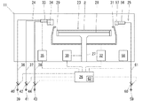
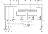
各基板処理室11〜22は、同様の構成となっており、代表して基板処理室11の構成について説明する。基板処理室11は、図2に示すように、基板2を水平に保持しながら回転させるための基板保持手段23と、基板保持手段23で保持した基板2の上面に向けて洗浄液を吐出するための洗浄液吐出手段24と、基板保持手段23で保持した基板2の上面に向けてリンス液を吐出するためのリンス液吐出手段25とを有しており、これらの基板保持手段23と洗浄液吐出手段24とリンス液吐出手段25を制御手段26で制御するように構成している。なお、制御手段26は、基板搬送装置8,10など基板液処理装置1の全体を制御するようにしている。
Each of the
基板保持手段23は、回転軸27の上端部に円板状のテーブル28を水平に取付けるとともに、テーブル28の周縁部に基板2の周縁部と接触して基板2を水平に保持する複数個の基板保持体29を円周方向に間隔をあけて取付けている。回転軸27には、回転駆動機構30を接続しており、回転駆動機構30によって回転軸27及びテーブル28を回転させ、テーブル28に基板保持体29で保持した基板2を回転させるようにしている。この回転駆動機構30は、制御手段26に接続しており、制御手段26で回転制御するようにしている。
The substrate holding means 23 horizontally attaches a disk-shaped table 28 to the upper end portion of the
また、基板保持手段23の周囲には、上方を開口させたカップ31が昇降自在に設けられ、テーブル28に載置した基板2をカップ31で囲んで洗浄液やリンス液の飛散を防止するとともに、洗浄液やリンス液を回収するようにしている。カップ31には、昇降機構32を接続しており、昇降機構32によってカップ31を基板2に対して相対的に上下に昇降させるようにしている。この昇降機構32は、制御手段26に接続しており、制御手段26で昇降制御するようにしている。
Further, a
洗浄液吐出手段24は、テーブル28よりも上方にアーム33を水平移動可能に配置し、アーム33の先端部に洗浄液吐出ノズルとして外部混合型の2流体ノズル34を取付けている。アーム33には、移動機構35を接続しており、移動機構35によって2流体ノズル34を基板2の外方の退避位置と基板2の中央部上方の開始位置との間で水平に移動させるようにしている。この移動機構35は、制御手段26に接続しており、制御手段26で移動制御するようにしている。なお、2流体ノズル34は、後述するように、第1の液体としての洗浄液と気体としての噴射ガスとを外部で混合して混合流体として基板2に向けて噴霧するとともに、噴霧した混合流体の外縁部に向けて第2の液体を供給するように構成している。
The cleaning liquid discharge means 24 is arranged so that the
また、洗浄液吐出手段24は、2流体ノズル34に第1の液体としての洗浄液を供給するための第1の液体供給流路36と、2流体ノズル34に気体としての噴射ガスを供給するための気体供給流路37と、2流体ノズル34に第2の液体を供給するための第2の液体供給流路38とを形成している。
The cleaning liquid discharge means 24 supplies a first
第1の液体供給流路36には、第1の液体(洗浄液)を供給するための第1の液体供給源39を流量調整器40を介して接続しており、流量調整器40によって2流体ノズル34に供給する洗浄液の流量を調整するようにしている。この流量調整器40は、制御手段26に接続しており、制御手段26で開閉制御及び流量制御するようにしている。
A first
気体供給流路37には、気体(噴射ガス)を供給するための気体供給源41を流量調整器42を介して接続しており、流量調整器42によって2流体ノズル34に供給する噴射ガスの流量を調整するようにしている。この流量調整器42は、制御手段26に接続しており、制御手段26で開閉制御及び流量制御するようにしている。
A
第2の液体供給流路38には、第2の液体を供給するための第2の液体供給源43を流量調整器44を介して接続しており、流量調整器44によって2流体ノズル34に供給する第2の液体の流量を調整するようにしている。この流量調整器44は、制御手段26に接続しており、制御手段26で開閉制御及び流量制御するようにしている。なお、第2の液体は、第1の液体と同一種類の液体でもよく、また、第1の液体とは異なる種類の液体でもよい。第2の液体として第1の液体と同一種類で同一濃度の液体を用いた場合には、第2の液体を供給しても基板2の表面で第1の液体の濃度変化が生じないようにすることができる。第2の液体として第1の液体と異なる種類の液体を用いる場合には、たとえばSC−1と純水の組合せのようにエッチングレートに影響を与えない組合せとすることが好ましい。
A second
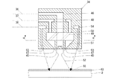
2流体ノズル34は、図3〜図5に示すように、第1の液体を吐出するための第1の液体吐出口45として下端面(先端面)の中央部に同一円上に複数個(ここでは、12個)の丸孔を形成している。これらの第1の液体吐出口45は、わずかに2流体ノズル34の外周方向に向けて傾斜させた状態で形成している。また、2流体ノズル34は、第1の液体吐出口45に連通する第1の液体連通路46を内部に形成し、その第1の液体連通路46に第1の液体供給流路36を接続している。これにより、2流体ノズル34は、第1の液体供給流路36から供給される第1の液体を第1の液体吐出口45から基板2に向けて外方へ拡散させながら吐出するようにしている。
As shown in FIGS. 3 to 5, the two-
また、2流体ノズル34は、気体を吐出するための気体吐出口47として第1の液体吐出口45の外方にスリット状の円環孔を第1の液体吐出口45と同心円上に形成している。また、2流体ノズル34は、気体吐出口47に連通する気体連通路48を内部に形成し、その気体連通路48に気体供給流路37を接続している。気体連通路48には、上流側(上面側)から下流側(下面側)に向けて上面視で右回り(時計回り)に回転しながら傾斜させた複数個(ここでは、12個)の旋回通路49を形成した旋回流発生部50を介設するとともに、上流側から下流側に向けて2流体ノズル34の内周側に傾斜させた傾斜通路51を形成している。これにより、2流体ノズル34は、気体供給流路37から供給される気体を気体吐出口47から基板2に向けて2流体ノズル34の内周側へ旋回させながら吐出するようにしている。そして、2流体ノズル34は、第1の液体吐出口45から吐出した第1の液体に気体吐出口47から吐出した気体を吹き付けることによって、2流体ノズル34の先端外部(下方)で第1の液体と気体とを混合して第1の液体の液滴が拡散した状態の混合流体52を生成し、その混合流体52を基板2の表面に噴霧するようにしている。
The two-
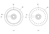
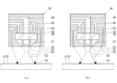
さらに、2流体ノズル34は、第2の液体を吐出するための第2の液体吐出口53として下端面(先端面)の気体吐出口47の外方にスリット状の円環孔を気体吐出口47と同心円上に形成している。この第2の液体吐出口53は、わずかに2流体ノズル34の中心方向に向けて傾斜させた状態で形成している。また、2流体ノズル34は、第2の液体吐出口53に連通する第2の液体連通路54を内部に形成し、その第2の液体連通路54に第2の液体供給流路38を接続している。この第2の液体吐出口53は、基板2に噴霧した混合流体52の基板表面上での外縁部55(外周部)又はその外縁部55よりも内側に向けて第2の液体が供給されるように2流体ノズル34の中心方向に向けて傾斜させている。これにより、2流体ノズル34は、第2の液体供給流路38から供給される第2の液体を第2の液体吐出口53から基板2の表面に噴霧された混合流体52の基板表面上での外縁部55又はその内側に向けて供給するようにしている。なお、2流体ノズル34は、図4(b)に示すように、2流体ノズル34の下端面(先端面)の気体吐出口47の外方に気体吐出口47と同心円上に配置した複数個(ここでは、24個)の丸孔で第2の液体吐出口53'を形成してもよい。また、2流体ノズル34は、第1の液体吐出口45及び気体吐出口47と一体的に第2の液体吐出口53,53'を形成した場合に限られず、既存の2流体ノズルに第2の液体吐出口を別体で取付けた構成としてもよい。さらに、2流体ノズル34は、第1の液体供給流路36及び流量調整器40と第2の液体供給流路38及び流量調整器44とを別個に設けて、第1及び第2の液体として異なる種類の液体を使用でき、それぞれ独立して流量や吐出タイミングなどを調整できるようにしているが、これらを一体的に設けて構成を簡素化させることもできる。
Further, the two-
リンス液吐出手段25は、図2に示すように、テーブル28よりも上方にアーム56を水平移動可能に配置し、アーム56の先端部にリンス液吐出ノズル57を取付けている。アーム56には、移動機構58を接続しており、移動機構58によってリンス液吐出ノズル57を基板2の外方の退避位置と基板2の中央直上方の開始位置との間で移動させるようにしている。この移動機構58は、制御手段26に接続しており、制御手段26で移動制御するようにしている。
As shown in FIG. 2, the rinse liquid discharge means 25 is arranged such that the
また、リンス液吐出手段25は、リンス液を供給するためのリンス液供給源59にリンス液吐出ノズル57を流量調整器60とリンス液供給流路61を介して接続しており、流量調整器60によってリンス液吐出ノズル57に供給するリンス液の流量を調整するようにしている。この流量調整器60は、制御手段26に接続しており、制御手段26で開閉制御及び流量制御するようにしている。
The rinsing liquid discharge means 25 has a rinsing
基板液処理装置1は、以上に説明したように構成しており、制御手段26(コンピュータ)で読み取り可能な記録媒体62に記録した基板液処理プログラムにしたがって各基板処理室11〜22で基板2を処理するようにしている。なお、記録媒体62は、基板液処理プログラム等の各種プログラムを記録できる媒体であればよく、ROMやRAMなどの半導体メモリ型の記録媒体であってもハードディスクやCD−ROMなどのディスク型の記録媒体であってもよい。
The substrate liquid processing apparatus 1 is configured as described above, and the
上記基板液処理装置1では、基板液処理プログラムによって図6に示す工程に従って以下に説明するようにして基板2の処理を行うようにしている。
In the substrate liquid processing apparatus 1, the
まず、基板液処理プログラムは、図6に示すように、基板搬送装置10から基板2を各基板処理室11〜22の基板保持手段23で受取る基板受取工程を実行する。
First, as shown in FIG. 6, the substrate liquid processing program executes a substrate receiving process in which the
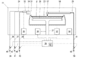
この基板受取工程において基板液処理プログラムは、図7に示すように、基板処理室11において、制御手段26によって基板保持手段23の昇降機構32を制御してカップ31を所定位置まで降下させ、その後、基板搬送装置10から基板2を受け取り、基板2を基板保持体29で支持し、その後、制御手段26によって基板保持手段23の昇降機構32を制御してカップ31を所定位置まで上昇させる。
In the substrate receiving process, as shown in FIG. 7, the substrate liquid processing program controls the elevating
次に、基板液処理プログラムは、図6に示すように、基板受取工程で受取った基板2に対して各種の処理液を用いて液処理する液処理工程を実行する。
Next, as shown in FIG. 6, the substrate liquid processing program executes a liquid processing process in which liquid processing is performed on the
次に、基板液処理プログラムは、図6に示すように、液処理工程で液処理した基板2に対してリンス液でリンス処理するリンス処理工程を実行する。
Next, as shown in FIG. 6, the substrate liquid processing program executes a rinsing process for rinsing with a rinsing liquid on the
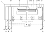
このリンス処理工程において基板液処理プログラムは、図8に示すように、基板処理室11において、制御手段26によって回転駆動機構30を制御して基板保持手段23のテーブル28及びテーブル28の基板保持体29で保持する基板2を所定回転速度で回転させ、制御手段26によって移動機構58を制御してリンス液吐出手段25のリンス液吐出ノズル57を基板2の中央部上方の開始位置に移動させ、制御手段26によって流量調整器60を開放及び流量制御してリンス液供給源59から供給されるリンス液をリンス液吐出ノズル57から基板2の上面に向けて一定時間吐出させ、その後、制御手段26によって流量調整器60を閉塞制御してリンス液吐出ノズル57からのリンス液の吐出を停止し、制御手段26によって移動機構58を制御してリンス液吐出手段25のリンス液吐出ノズル57を基板2の外周外方の退避位置に移動させる。
In this rinsing process, as shown in FIG. 8, the substrate liquid processing program controls the
次に、基板液処理プログラムは、図6に示すように、リンス処理工程でリンス処理した基板2に対して洗浄液で洗浄処理する洗浄処理工程を実行する。この洗浄処理工程では、先に2流体ノズル34から第2の液体だけを供給する第2の液体の供給工程を実行し、その後、引き続き第2の液体を供給しながら2流体ノズル34から第1の液体と気体とを吐出して外部で混合することで混合流体を噴霧する混合流体の噴霧工程を実行する。
Next, as shown in FIG. 6, the substrate liquid processing program executes a cleaning process step of cleaning the
第2の液体の供給工程において基板液処理プログラムは、図9に示すように、基板処理室11において、制御手段26によって回転駆動機構30を制御して基板保持手段23のテーブル28及びテーブル28の基板保持体29で保持する基板2を所定回転速度で回転させるとともに、制御手段26によって移動機構35を制御して洗浄液吐出手段24の2流体ノズル34を基板2の中央部上方の開始位置に移動させ、制御手段26によって流量調整器44を開放及び流量制御して第2の液体供給源43から供給される第2の液体を2流体ノズル34の第2の液体吐出口53から基板2の上面に向けて吐出させる。これにより、リンス液に加えて第2の液体を基板2に供給して基板2の上面に所定膜厚の液膜63を形成する。この時に、液膜63の膜厚は、2流体ノズル34から吐出される混合流体の吐出圧力によって基板2の上面に形成されたパターンが倒壊する等のダメージを受けるほど薄くはなく、基板2の上面のパーティクルに吐出圧力が及ばなくなるほど厚くはないようにする。
In the second liquid supply process, as shown in FIG. 9, the substrate liquid processing program controls the
その後、混合流体の噴霧工程において基板液処理プログラムは、図10に示すように、基板処理室11において、制御手段26によって回転駆動機構30を制御して基板保持手段23のテーブル28及びテーブル28の基板保持体29で保持する基板2を所定回転速度で回転させたまま、かつ、制御手段26によって流量調整器44を開放及び流量制御して第2の液体供給源43から供給される第2の液体を2流体ノズル34の第2の液体吐出口53から基板2の上面に向けて吐出させたままの状態で、制御手段26によって流量調整器40,42を開放及び流量制御して第1の液体供給源39及び気体供給源41から供給される第1の液体及び気体を2流体ノズル34の第1の液体吐出口45及び気体吐出口47から基板2の上面に向けて吐出させる。これにより、第1の液体吐出口45から吐出された第1の液体と気体吐出口47から吐出された気体とが2流体ノズル34の先端より下方の外部において混合されて霧状の混合流体となり、混合流体が基板2に噴霧される。その後、基板液処理プログラムは、制御手段26によって移動機構35を制御してアーム33を水平に往復移動させることで2流体ノズル34を基板2の中央部上方と基板2の外周端縁上方との間で往復移動させて基板2の洗浄を行い、その後、制御手段26によって流量調整器40,42,44を閉塞制御して2流体ノズル34からの第1及び第2の液体並びに気体の吐出を停止し、制御手段26によって移動機構35を制御して洗浄液吐出手段24の2流体ノズル34を基板2の外周外方の退避位置に移動させる。
After that, in the mixed fluid spraying process, as shown in FIG. 10, the substrate liquid processing program controls the
このように、基板液処理プログラムでは、基板2に噴霧された混合流体の基板表面上での外縁部に第2の液体を供給しながら基板2の洗浄処理を行うようにしている。
Thus, in the substrate liquid processing program, the
基板2の上面に形成されたパターンが倒壊する等のダメージを受けないようにするためには、基板2の上面の液膜63が形成されている部分に混合流体を噴霧することが好ましい。しかし、混合流体だけを噴霧した場合には、基板2に噴霧される混合流体の基板表面上での外縁部において気体吐出口47から吐出される気体の吐出圧力の作用によって液膜63の膜厚が薄くなってしまう。そのため、基板液処理プログラムでは、基板2に噴霧された混合流体の外縁部に第2の液体吐出口53から第2の液体を供給することで、基板2に噴霧された混合流体の基板表面上での外縁部において液膜63が薄膜化してしまうのを防止している。特に、基板液処理プログラムでは、第2の液体の供給工程を行った後に混合流体の噴霧工程を行うことで、混合流体が噴霧される基板2の表面にリンス液による液膜に加えて第2の液体を供給して、混合流体が噴霧される前にパターンの倒壊などのダメージを抑制しつつ洗浄効果が得られる膜厚の液膜を形成している。これにより、混合流体の噴霧の開始直後においてもパターンの倒壊などのダメージを受けるほどの液膜の薄膜化を防止できるようにしている。また、基板液処理プログラムでは、第2の液体を混合流体の流れを乱さない流速で吐出することで、混合流体の噴霧による洗浄効果が低減しないようにしている。
In order to prevent damage such as collapse of the pattern formed on the upper surface of the
この第2の液体の供給は、基板2に噴霧された混合流体の基板表面上での外縁部に到達するように供給されればよく、図11(a)に示すように、第2の液体吐出口53から基板2に噴霧された混合流体の基板表面上での外縁部に向けて第2の液体を直接的に吐出した場合に限られず、図11(b)に示すように、第2の液体吐出口53から混合流体の基板表面上での外縁部よりも内側に向けて第2の液体を吐出して、気体吐出口47から吐出される気体によって第2の液体を混合流体の基板表面上での外縁部に供給するようにしてもよい。この場合、第2の液体は、旋回流を形成している気体の外縁部に沿って流れ、混合流体の基板表面上での外縁部に供給される。この時に、第2の液体が気体と衝突することで基板2の表面での気体の圧力が低減して、より一層液膜63の薄膜化が防止され、パターンの倒壊などのダメージの発生が抑制される。
The second liquid may be supplied so as to reach the outer edge of the mixed fluid sprayed on the
この洗浄処理工程において基板液処理プログラムは、制御手段26によって第1及び第2の液体供給流路36,38の流量調整器40,44や気体供給流路37の流量調整器42をそれぞれ別個に制御するようにしている。これにより、第1及び第2の液体として異なる種類の液体を使用することができるとともに、流量や吐出タイミングなどをそれぞれ独立して調整することができ、気体の吐出圧力に応じた膜厚の液膜を形成することができる。
In this cleaning process, the substrate liquid processing program causes the control means 26 to separately set the
次に、基板液処理プログラムは、図6に示すように、洗浄処理工程で洗浄処理した基板2を乾燥処理する乾燥処理工程を実行する。
Next, as shown in FIG. 6, the substrate liquid processing program executes a drying process for drying the
この乾燥処理工程において基板液処理プログラムは、基板処理室11において、制御手段26によって回転駆動機構30を制御して基板保持手段23のテーブル28及びテーブル28の基板保持体29で保持する基板2をこれまでの液処理(洗浄処理、リンス処理)時よりも高速な回転速度で回転させることによって、遠心力の作用で基板2の上面からリンス液を振り切って基板2を乾燥させるようにしている。
In this drying processing step, the substrate liquid processing program controls the
基板液処理プログラムは、最後に、図6に示すように、基板2を各基板処理室11〜22の基板保持手段23から基板搬送装置10に受渡す基板受渡工程を実行する。
Finally, as shown in FIG. 6, the substrate liquid processing program executes a substrate delivery process for delivering the
この基板受渡工程において基板液処理プログラムは、図12に示すように、基板処理室11において、制御手段26によって基板保持手段23の昇降機構32を制御してカップ31を所定位置まで降下させ、その後、基板保持体29で支持した基板2を基板搬送装置10に受け渡し、その後、制御手段26によって基板保持手段23の昇降機構32を制御してカップ31を所定位置まで上昇させる。なお、この基板受渡工程は、先の基板受取工程と同時に行うようにすることもできる。
In this substrate delivery process, as shown in FIG. 12, the substrate liquid processing program controls the
以上に説明したように、上記基板液処理装置1では、基板2(被処理体)に噴霧された混合流体の基板表面上での外縁部に第2の液体を供給しながら基板2の液処理(洗浄)を行うようにしている。
As described above, in the substrate liquid processing apparatus 1, the liquid processing of the
そのため、上記基板液処理装置1における基板液処理においては、基板2に噴霧された混合流体の基板表面上での外縁部に第2の液体吐出口53から第2の液体を供給することで、基板2に噴霧された混合流体の基板表面上での外縁部において液膜63が薄膜化してしまうのを防止することができ、基板2の表面が受けるダメージを防止して良好に基板2の液処理(洗浄)を行うことができる。
Therefore, in the substrate liquid processing in the substrate liquid processing apparatus 1, by supplying the second liquid from the second
1 基板液処理装置 2 基板
3 キャリア 4 基板搬入出部
5 基板搬送部 6 基板処理部
7 前壁 8 基板搬送装置
9 基板受渡台 10 基板搬送装置
11〜22 基板処理室 23 基板保持手段
24 洗浄液吐出手段 25 リンス液吐出手段
26 制御手段 27 回転軸
28 テーブル 29 基板保持体
30 回転駆動機構 31 カップ
32 昇降機構 33 アーム
34 2流体ノズル 35 移動機構
36 第1の液体供給流路 37 気体供給流路
38 第2の液体供給流路 39 第1の液体供給源
40 流量調整器 41 気体供給源
42 流量調整器 43 第2の液体供給源
44 流量調整器 45 第1の液体吐出口
46 第1の液体連通路 47 気体吐出口
48 気体連通路 49 旋回通路
50 旋回流発生部 51 傾斜通路
52 混合流体 53,53' 第2の液体吐出口
54 第2の液体連通路 55 外縁部
56 アーム 57 リンス液吐出ノズル
58 移動機構 59 リンス液供給源
60 流量調整器 61 リンス液供給流路
62 記録媒体 63 液膜
DESCRIPTION OF SYMBOLS 1 Substrate
11-22
24 Cleaning liquid discharge means 25 Rinsing liquid discharge means
26 Control means 27 Rotating shaft
28 Table 29 Substrate holder
30
32
34 Two-
36 First
38 Second
40
42
44
46 First
48
50
52
54 Second
56
58
60
62
Claims (14)
前記被処理体に噴霧された混合流体の被処理体上での外縁部に第2の液体を供給するための第2の液体吐出口を有することを特徴とする2流体ノズル。 A first liquid discharge port that discharges the first liquid and a gas discharge port that discharges gas, and the first liquid discharged from the first liquid discharge port and the gas discharge port discharged from the first liquid discharge port In the two-fluid nozzle that mixes the gas with the outside and sprays the mixed fluid toward the workpiece,
A two-fluid nozzle having a second liquid discharge port for supplying a second liquid to an outer edge portion of the mixed fluid sprayed on the object to be processed on the object to be processed.
前記2流体ノズルは、前記基板に噴霧された混合流体の基板上での外縁部に第2の液体を供給するための第2の液体吐出口を有することを特徴とする基板液処理装置。 The first liquid and the gas discharged from the first liquid discharge port using a two-fluid nozzle having a first liquid discharge port for discharging the first liquid and a gas discharge port for discharging a gas. In the substrate liquid processing apparatus that performs liquid processing of the substrate by mixing the gas discharged from the discharge port outside and spraying the mixed fluid toward the substrate,
The substrate fluid processing apparatus, wherein the two-fluid nozzle has a second liquid discharge port for supplying a second liquid to an outer edge portion of the mixed fluid sprayed on the substrate on the substrate.
前記基板に噴霧された混合流体の基板上での外縁部に第2の液体を供給しながら前記基板の液処理を行うことを特徴とする基板液処理方法。 In a substrate liquid processing method for performing liquid processing on a substrate by spraying a mixed fluid toward the substrate using a two-fluid nozzle that discharges the first liquid and gas and mixes them externally,
A substrate liquid processing method, comprising: performing liquid processing on the substrate while supplying a second liquid to an outer edge portion of the mixed fluid sprayed on the substrate on the substrate.
前記基板に噴霧された混合流体の基板上での外縁部に第2の液体を供給しながら前記基板の液処理を行うことを特徴とする基板液処理プログラムを記録したコンピュータ読み取り可能な記録媒体。 Computer-readable recording of a substrate liquid processing program for performing liquid processing on a substrate by spraying the mixed fluid toward the substrate using a two-fluid nozzle that discharges the first liquid and gas and mixes them externally In a recording medium
A computer-readable recording medium on which a substrate liquid processing program is recorded, wherein the liquid processing of the substrate is performed while supplying a second liquid to an outer edge portion of the mixed fluid sprayed on the substrate on the substrate.
Priority Applications (3)
| Application Number | Priority Date | Filing Date | Title |
|---|---|---|---|
| JP2011050958A JP5470306B2 (en) | 2011-03-09 | 2011-03-09 | Two-fluid nozzle, substrate liquid processing apparatus, substrate liquid processing method, and computer-readable recording medium recording a substrate liquid processing program |
| KR1020120022479A KR101566274B1 (en) | 2011-03-09 | 2012-03-05 | Two-fluid nozzle, substrate liquid processing apparatus, substrate liquid processing method, and computer-readable storage medium for storing substrate liquid processing program |
| US13/413,788 US20120227770A1 (en) | 2011-03-09 | 2012-03-07 | Two-fluid nozzle, substrate liquid processing apparatus, substrate liquid processing method, and computer-readable storage medium for storing substrate liquid processing method |
Applications Claiming Priority (1)
| Application Number | Priority Date | Filing Date | Title |
|---|---|---|---|
| JP2011050958A JP5470306B2 (en) | 2011-03-09 | 2011-03-09 | Two-fluid nozzle, substrate liquid processing apparatus, substrate liquid processing method, and computer-readable recording medium recording a substrate liquid processing program |
Publications (2)
| Publication Number | Publication Date |
|---|---|
| JP2012190868A true JP2012190868A (en) | 2012-10-04 |
| JP5470306B2 JP5470306B2 (en) | 2014-04-16 |
Family
ID=46794399
Family Applications (1)
| Application Number | Title | Priority Date | Filing Date |
|---|---|---|---|
| JP2011050958A Expired - Fee Related JP5470306B2 (en) | 2011-03-09 | 2011-03-09 | Two-fluid nozzle, substrate liquid processing apparatus, substrate liquid processing method, and computer-readable recording medium recording a substrate liquid processing program |
Country Status (3)
| Country | Link |
|---|---|
| US (1) | US20120227770A1 (en) |
| JP (1) | JP5470306B2 (en) |
| KR (1) | KR101566274B1 (en) |
Cited By (6)
| Publication number | Priority date | Publication date | Assignee | Title |
|---|---|---|---|---|
| JP2015037147A (en) * | 2013-08-15 | 2015-02-23 | 株式会社ディスコ | Cleaning device and cleaning method |
| JP2015109327A (en) * | 2013-12-04 | 2015-06-11 | 株式会社ディスコ | Cleaning device |
| JP2015198217A (en) * | 2014-04-03 | 2015-11-09 | 株式会社ディスコ | Cleaning device and cleaning method of workpiece |
| KR20160041926A (en) * | 2013-08-13 | 2016-04-18 | 싸므 테크놀로지 | Atomizer for a lubricant product and lubrication system comprising said atomizer |
| JP2016530091A (en) * | 2013-08-13 | 2016-09-29 | サメ テクノロジ | Spraying device for liquid coating products and spraying facility comprising such a spraying device |
| KR101776019B1 (en) | 2015-07-31 | 2017-09-07 | 세메스 주식회사 | Nozzle and Apparatus for treating Substrate with the nozzle |
Families Citing this family (12)
| Publication number | Priority date | Publication date | Assignee | Title |
|---|---|---|---|---|
| MX343152B (en) | 2011-07-28 | 2016-10-26 | 3M Innovative Properties Co | Spray head assembly with integrated air cap/nozzle for a liquid spray gun. |
| KR102037921B1 (en) * | 2012-10-22 | 2019-11-26 | 세메스 주식회사 | Apparatus and Method for treating substrate |
| SG10201407598VA (en) | 2013-11-19 | 2015-06-29 | Ebara Corp | Substrate cleaning apparatus and substrate processing apparatus |
| KR102246656B1 (en) * | 2013-12-27 | 2021-05-03 | 세메스 주식회사 | Nozzle unit, apparatus for treating substrate, and method for treating substrate and using the apparatus |
| PL2907582T3 (en) * | 2014-02-17 | 2018-02-28 | Erbe Elektromedizin Gmbh | Method and nozzle for mixing and spraying medical fluids |
| KR102432858B1 (en) * | 2015-09-01 | 2022-08-16 | 삼성전자주식회사 | Chemical liguid supply apparatus and semiconductor processing apparatus having the same |
| KR101817212B1 (en) * | 2016-04-29 | 2018-02-21 | 세메스 주식회사 | Chemical nozzle and apparatus for treating substrate |
| MX2019002858A (en) | 2016-09-13 | 2019-06-12 | Spectrum Brands Inc | Swirl pot shower head engine. |
| KR101987709B1 (en) * | 2017-05-31 | 2019-06-11 | (주)엔피홀딩스 | Nozzle for spraying mixed flow of four |
| DE102020213695A1 (en) * | 2019-12-04 | 2021-06-10 | Lechler Gmbh | Bundle nozzle for spraying a fluid, arrangement with a bundle nozzle and method for producing a bundle nozzle |
| KR102707740B1 (en) * | 2022-08-02 | 2024-09-19 | 세메스 주식회사 | Unit for supplying chemical and Apparatus for treating substrate with the unit |
| KR20240112564A (en) * | 2023-01-12 | 2024-07-19 | 삼성전자주식회사 | Chemical mechanical polishing apparatus |
Citations (5)
| Publication number | Priority date | Publication date | Assignee | Title |
|---|---|---|---|---|
| JPS5936854U (en) * | 1983-07-09 | 1984-03-08 | ボルカノ株式会社 | filth water excrement spray nozzle |
| JP2002151455A (en) * | 2000-08-31 | 2002-05-24 | Super Silicon Kenkyusho:Kk | Cleaning apparatus for semiconductor wafer |
| JP2003273070A (en) * | 2002-03-19 | 2003-09-26 | Shibaura Mechatronics Corp | Substrate processing apparatus and substrate processing method |
| JP2005288390A (en) * | 2004-04-02 | 2005-10-20 | Kyoritsu Gokin Co Ltd | Two-fluid nozzle and spraying method |
| JP2008112837A (en) * | 2006-10-30 | 2008-05-15 | Dainippon Screen Mfg Co Ltd | Two-fluid nozzle, and substrate processing apparatus and substrate processing method using the same |
-
2011
- 2011-03-09 JP JP2011050958A patent/JP5470306B2/en not_active Expired - Fee Related
-
2012
- 2012-03-05 KR KR1020120022479A patent/KR101566274B1/en active Active
- 2012-03-07 US US13/413,788 patent/US20120227770A1/en not_active Abandoned
Patent Citations (5)
| Publication number | Priority date | Publication date | Assignee | Title |
|---|---|---|---|---|
| JPS5936854U (en) * | 1983-07-09 | 1984-03-08 | ボルカノ株式会社 | filth water excrement spray nozzle |
| JP2002151455A (en) * | 2000-08-31 | 2002-05-24 | Super Silicon Kenkyusho:Kk | Cleaning apparatus for semiconductor wafer |
| JP2003273070A (en) * | 2002-03-19 | 2003-09-26 | Shibaura Mechatronics Corp | Substrate processing apparatus and substrate processing method |
| JP2005288390A (en) * | 2004-04-02 | 2005-10-20 | Kyoritsu Gokin Co Ltd | Two-fluid nozzle and spraying method |
| JP2008112837A (en) * | 2006-10-30 | 2008-05-15 | Dainippon Screen Mfg Co Ltd | Two-fluid nozzle, and substrate processing apparatus and substrate processing method using the same |
Cited By (9)
| Publication number | Priority date | Publication date | Assignee | Title |
|---|---|---|---|---|
| KR20160041926A (en) * | 2013-08-13 | 2016-04-18 | 싸므 테크놀로지 | Atomizer for a lubricant product and lubrication system comprising said atomizer |
| JP2016530091A (en) * | 2013-08-13 | 2016-09-29 | サメ テクノロジ | Spraying device for liquid coating products and spraying facility comprising such a spraying device |
| JP2016532551A (en) * | 2013-08-13 | 2016-10-20 | サメ テクノロジ | Lubricating system including sprayer and sprayer for lubricant products |
| KR102214363B1 (en) | 2013-08-13 | 2021-02-09 | 싸므 크렘린 | Atomizer for a lubricant product and lubrication system comprising said atomizer |
| JP2015037147A (en) * | 2013-08-15 | 2015-02-23 | 株式会社ディスコ | Cleaning device and cleaning method |
| JP2015109327A (en) * | 2013-12-04 | 2015-06-11 | 株式会社ディスコ | Cleaning device |
| JP2015198217A (en) * | 2014-04-03 | 2015-11-09 | 株式会社ディスコ | Cleaning device and cleaning method of workpiece |
| KR101776019B1 (en) | 2015-07-31 | 2017-09-07 | 세메스 주식회사 | Nozzle and Apparatus for treating Substrate with the nozzle |
| US10005092B2 (en) | 2015-07-31 | 2018-06-26 | Semes Co., Ltd. | Nozzle and substrate treating apparatus including the same |
Also Published As
| Publication number | Publication date |
|---|---|
| KR20120103465A (en) | 2012-09-19 |
| JP5470306B2 (en) | 2014-04-16 |
| KR101566274B1 (en) | 2015-11-05 |
| US20120227770A1 (en) | 2012-09-13 |
Similar Documents
| Publication | Publication Date | Title |
|---|---|---|
| JP5470306B2 (en) | Two-fluid nozzle, substrate liquid processing apparatus, substrate liquid processing method, and computer-readable recording medium recording a substrate liquid processing program | |
| JP5732376B2 (en) | Two-fluid nozzle, substrate liquid processing apparatus, and substrate liquid processing method | |
| KR101889145B1 (en) | Substrate processing method and substrate processing apparatus | |
| CN103165496B (en) | Substrate board treatment and substrate processing method using same | |
| KR101883013B1 (en) | Substrate processing apparatus, substrate processing method and computer-readable storage medium | |
| JP5832397B2 (en) | Substrate processing apparatus and substrate processing method | |
| US8607807B2 (en) | Liquid treatment apparatus and method | |
| US9022045B2 (en) | Substrate liquid cleaning apparatus with controlled liquid port ejection angle | |
| KR100949090B1 (en) | Spin unit and substrate processing apparatus having same | |
| TWI620238B (en) | Substrate processing method and substrate processing device | |
| JP2020115513A (en) | Substrate processing method and substrate processing apparatus | |
| KR102346493B1 (en) | Substrate processing method and substrate processing apparatus | |
| US10546763B2 (en) | Substrate treatment method and substrate treatment device | |
| CN112997277B (en) | Substrate processing device and substrate processing device cleaning method | |
| JP2009117826A (en) | Substrate processing apparatus and method | |
| JP6069398B2 (en) | Two-fluid nozzle, substrate liquid processing apparatus, and substrate liquid processing method | |
| CN121400126A (en) | Substrate processing method and substrate processing apparatus | |
| JP2008166346A (en) | Apparatus and method for processing substrate | |
| JP2018093142A (en) | Substrate processing apparatus, substrate processing method, and storage medium | |
| KR20150144915A (en) | Substrate treating apparatus and method |
Legal Events
| Date | Code | Title | Description |
|---|---|---|---|
| A621 | Written request for application examination |
Free format text: JAPANESE INTERMEDIATE CODE: A621 Effective date: 20130208 |
|
| A977 | Report on retrieval |
Free format text: JAPANESE INTERMEDIATE CODE: A971007 Effective date: 20130613 |
|
| A131 | Notification of reasons for refusal |
Free format text: JAPANESE INTERMEDIATE CODE: A131 Effective date: 20130625 |
|
| A521 | Request for written amendment filed |
Free format text: JAPANESE INTERMEDIATE CODE: A523 Effective date: 20130822 |
|
| TRDD | Decision of grant or rejection written | ||
| A01 | Written decision to grant a patent or to grant a registration (utility model) |
Free format text: JAPANESE INTERMEDIATE CODE: A01 Effective date: 20140107 |
|
| A61 | First payment of annual fees (during grant procedure) |
Free format text: JAPANESE INTERMEDIATE CODE: A61 Effective date: 20140203 |
|
| R150 | Certificate of patent or registration of utility model |
Free format text: JAPANESE INTERMEDIATE CODE: R150 |
|
| LAPS | Cancellation because of no payment of annual fees |