JP2012182505A - Component mounting system - Google Patents
Component mounting system Download PDFInfo
- Publication number
- JP2012182505A JP2012182505A JP2012144631A JP2012144631A JP2012182505A JP 2012182505 A JP2012182505 A JP 2012182505A JP 2012144631 A JP2012144631 A JP 2012144631A JP 2012144631 A JP2012144631 A JP 2012144631A JP 2012182505 A JP2012182505 A JP 2012182505A
- Authority
- JP
- Japan
- Prior art keywords
- tray
- head
- component
- holding
- height
- Prior art date
- Legal status (The legal status is an assumption and is not a legal conclusion. Google has not performed a legal analysis and makes no representation as to the accuracy of the status listed.)
- Granted
Links
Images


Landscapes
- Supply And Installment Of Electrical Components (AREA)
Abstract
Description
本発明は、部品装着システムに関するものであり、特に、トレイ型部品供給装置により、あるいはトレイ型部品供給装置とフィーダ型部品供給装置との両方により供給される電子回路部品を回路基板に装着する部品装着システムに関するものである。 The present invention relates to a component mounting system, and in particular, a component for mounting an electronic circuit component supplied by a tray-type component supply device or by both a tray-type component supply device and a feeder-type component supply device on a circuit board. It relates to the mounting system.
この種の部品装着システムは、例えば、下記特許文献1に記載されているように、従来、よく知られている。特許文献1に記載の部品装着システムの供給装置本体には、フィーダ型部品供給装置のフィーダを位置決めするためのピンが複数設けられ、それらピンの各々により位置決めされて複数のフィーダがY軸方向に並んでセットされる。Y軸方向は、部品吸着ヘッドの移動平面である水平面内において互いに直交する2方向のうちの一方であり、他方をX軸方向とする。
This type of component mounting system is well known in the art as described in, for example,
供給装置本体にはまた、トレイ型部品供給装置のトレイホルダがフィーダと共に取り付けられ、あるいはトレイホルダのみが取り付けられる。トレイホルダのテーブルには、その前面と両側面とにそれぞれ突き当て部が設けられている。また、テーブルの上面には、雌ねじ穴が複数設けられ、突き当てピンが螺合されるようにされるとともに、前後方向に延びる長穴が複数設けられ、各長穴にクランプ装置が移動可能に嵌合されている。クランプ装置は、両端に大径部を備えて長穴に嵌合されたピンと、そのピンに軸方向に相対移動可能に嵌合された押さえ板と、押さえ板をテーブル側に付勢するばねとを含み、ばねの付勢により押さえ板がテーブル上のトレイに、ピンの大径部の一方がテーブルの裏面にそれぞれ押し付けられて固定される。 The tray holder of the tray-type component supply device is also attached to the supply device main body together with the feeder, or only the tray holder is attached. The table of the tray holder is provided with abutting portions on the front surface and both side surfaces thereof. In addition, a plurality of female screw holes are provided on the upper surface of the table so that the butting pins are screwed together, and a plurality of long holes extending in the front-rear direction are provided, and the clamp device can be moved in each long hole. It is mated. The clamp device includes a pin having a large-diameter portion at both ends and fitted into an elongated hole, a holding plate fitted to the pin so as to be relatively movable in the axial direction, and a spring for biasing the holding plate toward the table side. The holding plate is pressed against the tray on the table and one of the large-diameter portions of the pin is pressed against the back surface of the table by the spring force.
トレイをテーブルに載置する場合には、突き当て部と突き当てピンとの少なくとも一方にトレイを突き当て、X軸方向とY軸方向とにおいてそれぞれ位置決めした状態でクランプ装置によってテーブルに固定する。そのため、突き当てピンによってトレイを位置決めする場合には、トレイの大きさおよび数に応じて、トレイの位置決めに適した位置にある雌ねじ穴に突き当てピンを螺合する。そして、突き当て部と突き当てピンとの少なくとも一方によってトレイを位置決めした状態でクランプ装置を長穴内において移動させ、押さえ板をトレイの縁部に掛け、その状態でばねによりテーブル側へ付勢して固定する。そのため、特許文献1に記載のトレイ型部品供給装置においては、クランプ装置が移動可能に設けられるとともに、突き当てピンの立設位置が選択可能とされることにより、大きさが異なる複数種類のトレイが複数枚あるいは大きさが同じであるトレイが複数枚、テーブル上に水平に、かつ、X軸方向およびY軸方向に並べて載置される。
しかしながら、上記トレイ型部品供給装置においては、テーブル上に複数枚のトレイがX軸方向およびY軸方向に並べて載置されるため、トレイからの電子回路部品の取出しが面倒になる。テーブル上に載置された複数枚のトレイの各々から電子回路部品を取り出す場合、トレイ毎に設定された基準位置に基づいて、トレイに並べられた複数の電子回路部品の各位置が取得され、部品吸着ヘッドを移動させ、電子回路部品を吸着させるのであるが、複数枚のトレイがX軸方向およびY軸方向に並んで設けられれば、電子回路部品を取り出す部品吸着ヘッドの移動可能範囲をX軸方向とY軸方向との両方に関して広くしなければならず、部品吸着ヘッドを移動させる装置が大形になる。また、両方向において基準位置を異にするトレイがあることとなり、電子回路部品を供給するトレイが替わる際にX
軸方向およびY軸方向において基準位置を設定し直すことが必要となる場合があり、制御が複雑になる。
そこで、本発明は、部品装着システムにおいてトレイ型部品供給装置からの電子回路部品の受取りを容易にすることを課題として為されたものである。
However, in the tray-type component supply device, since a plurality of trays are placed side by side on the table in the X-axis direction and the Y-axis direction, taking out the electronic circuit components from the tray becomes troublesome. When taking out electronic circuit components from each of the plurality of trays placed on the table, each position of the plurality of electronic circuit components arranged in the tray is acquired based on the reference position set for each tray, The component suction head is moved to suck the electronic circuit component. If a plurality of trays are provided side by side in the X-axis direction and the Y-axis direction, the movable range of the component suction head for taking out the electronic circuit component is set to X. Both the axial direction and the Y-axis direction must be widened, and the apparatus for moving the component suction head becomes large. Also, there will be trays with different reference positions in both directions, and when the tray for supplying electronic circuit components is changed,
It may be necessary to reset the reference position in the axial direction and the Y-axis direction, which complicates the control.
Therefore, the present invention has been made with an object of facilitating the reception of electronic circuit components from a tray-type component supply device in a component mounting system.
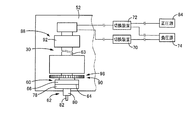
上記課題は、第1発明により、部品装着システムを、(A)(a)電子回路部品を平面状に並べて支持するトレイを複数枚平面状に並べて支持可能な支持面を有する支持板、および(b)前記支持面上において前記トレイを複数枚重ねた状態で位置決めするトレイ位置決め装置を備えたトレイ型部品供給装置と、(B)(a)装着機本体,(b)その装着機本体上に設けられて回路基板を保持する基板保持装置,および(c)前記トレイ型部品供給装置から電子回路部品を受け取って前記基板保持装置に保持された回路基板に装着する装着装置を備えた部品装着機とを含むものとし、かつ、前記部品装着機を、前記支持板の前記支持面上に複数枚重ねられたトレイのうち最上のものの高さを検出するトレイ高さ検出装置を含み、そのトレイ高さ検出装置が、上下方向に延びる嵌合穴を備えた検出装置本体と、その検出装置本体を昇降させる検出装置本体昇降装置と、前記検出装置本体の高さを検出する本体高さ検出装置と、前記検出装置本体の前記嵌合穴に摺動可能にかつ予め定められた突出位置に向かって付勢された状態で嵌合された検出子と、その検出子が前記突出位置から設定量後退したことを検出する後退検出装置とを含むものとすることによって解決される。
上記課題はまた、第2発明により、部品装着システムを、(A)電子回路部品を一列に並べて1個ずつ順次供給するフィーダを一直線に沿って複数並べて支持可能な第1支持面を形成する1枚の第1支持板を備えたフィーダ型部品供給装置と、(B)電子回路部品を平面状に並べて支持するトレイを複数枚、前記フィーダの並び方向に平行な方向に並べて支持可能な第2支持面を形成し、上下に重ねられることなく一重に設置される1枚の第2支持板を備え、前記第2支持面に前記トレイを複数枚積み重ねた状態で支持するトレイ型部品供給装置と、(C)(a)装着機本体と、(b)その装着機本体上に設けられ、前記回路基板を保持する基板保持装置と、(c)前記電子回路部品を保持する部品保持ヘッドを保持するヘッド保持装置およびそのヘッド保持装置を少なくとも前記第2支持面に平行な方向に移動させるヘッド移動装置を有して、前記トレイ型部品供給装置または前記フィーダ型部品供給装置から電子回路部品を受け取り、前記基板保持装置に保持された回路基板に装着する装着装置とを備えた部品装着機と、(D)前記部品保持ヘッドと選択的に前記ヘッド保持装置に保持可能な高さ検出ヘッドを備え、前記第2支持板の前記第2支持面に積み重ねられたトレイのうち一番上のものの高さを検出するトレイ高さ検出装置と、(D)前記トレイを保持するトレイ保持ヘッドを備え、そのトレイ保持ヘッドにより、前記トレイ高さ検出装置から供給される高さ情報に基づいて、前記第2支持面上に積み重ねられたトレイのうち一番上のものを保持して取り除くトレイ除去装置とを含むものとするとともに、前記第1支持面と前記第2支持面との前記複数のフィーダの並び方向に平行な方向の寸法である幅を互いにほぼ等しくし、前記高さ検出ヘッドを、(a)上下方向に延びる嵌合穴を備えた高さ検出ヘッド本体と、(b)その高さ検出ヘッド本体の前記嵌合穴に摺動可能にかつ予め定められた突出位置に向かって付勢された状態で嵌合された検出子と、(c)その検出子が前記突出位置から設定量後退したことを検出する後退検出装置と、(d)前記高さ検出ヘッド本体を昇降させる高さ検出ヘッド本体昇降装置と、(e)前記高さ検出ヘッド本体の高さを検出する本体高さ検出装置とを含むものとすることにより解決される。
複数のフィーダは、各部品供給部が一直線に沿って並べばよく、複数のフィーダの各部品供給部が一直線上に位置する状態で並べてもよく、一直線から外れた状態で並べてもよい。後者の場合、例えば、複数のフィーダが、各部品供給部が千鳥状に位置し、隣接するフィーダの各部品供給部が一直線に対して互いに反対側に位置するように配置される。
第1支持面は、水平面としてもよく、鉛直面,傾斜面等としてもよい。水平面の場合、フィーダは第1支持面により下方から支持され、鉛直面の場合、フィーダは第1支持面により、並び方向と直角な方向の一端部において支持される。
第1支持面の幅と第2支持面の幅とは、例えば、個々のトレイやフィーダの寸法の都合により全く同じになるとは限らず、ほぼ同じであればよい。
第1支持板および第2支持板は、部品装着機に固定されて設けられてもよく、着脱可能に設けられてもよい。
According to a first aspect of the present invention, there is provided a component mounting system comprising: (A) (a) a support plate having a support surface capable of supporting a plurality of trays that support electronic circuit components arranged in a plane, and b) a tray-type component supply device provided with a tray positioning device that positions the tray in a state where a plurality of the trays are stacked on the support surface; and (B) (a) a mounting machine body, and (b) on the mounting machine body A board holding device provided to hold the circuit board, and (c) a component mounting machine including a mounting device for receiving an electronic circuit component from the tray-type component supply device and mounting the electronic circuit component on the circuit board held by the board holding device And a tray height detection device for detecting the height of the uppermost tray among the plurality of trays stacked on the support surface of the support plate. The detection device extends vertically Detection device main body provided with a fitting hole, detection device main body lifting device for raising and lowering the detection device main body, main body height detection device for detecting the height of the detection device main body, and the fitting of the detection device main body A detector fitted in a slidable manner in the hole and biased toward a predetermined protruding position, and a retreat detecting device for detecting that the detector has moved back a set amount from the protruding position; It is solved by including.
According to the second aspect of the present invention, according to the second invention, (A) forming a first support surface capable of supporting a plurality of feeders arranged in a straight line and supporting (A) a plurality of feeders for sequentially supplying electronic circuit components one by one. A feeder-type component supply device including a first support plate; and (B) a second tray that supports a plurality of trays that support electronic circuit components arranged side by side in a plane, in a direction parallel to the arrangement direction of the feeders. A tray-type component supply device that forms a support surface, includes a single second support plate that is installed in a single layer without being stacked one above the other, and supports a plurality of the trays stacked on the second support surface; (C) (a) mounting machine body; (b) a board holding device provided on the mounting machine body for holding the circuit board; and (c) holding a component holding head for holding the electronic circuit component. Head holding device and the head holding device At least a head moving device for moving in a direction parallel to the second support surface, receiving an electronic circuit component from the tray-type component supply device or the feeder-type component supply device, and being held by the substrate holding device A component mounting machine including a mounting device mounted on the circuit board; and (D) a height detection head that can be selectively held by the head holding device and the component holding head, (2) a tray height detection device that detects the height of the top of the trays stacked on the support surface; and (D) a tray holding head that holds the tray. And a tray removing device that holds and removes the uppermost one of the trays stacked on the second support surface based on height information supplied from the height detecting device. The widths of the first support surface and the second support surface, which are dimensions in a direction parallel to the arrangement direction of the plurality of feeders, are substantially equal to each other, and the height detection head is (a) a fitting that extends in the vertical direction. A height detection head body provided with a joint hole; and (b) fitted in a state of being slidable and biased toward a predetermined protruding position in the fitting hole of the height detection head body. And (c) a backward detection device that detects that the detector has moved back a set amount from the protruding position, and (d) a height detection head main body lifting device that lifts and lowers the height detection head main body, (e) It is solved by including a main body height detecting device for detecting the height of the height detecting head main body.
The plurality of feeders may be arranged in a state where the respective component supply units are arranged along a straight line, may be arranged in a state where the respective component supply units of the plurality of feeders are positioned on a straight line, or may be arranged in a state deviated from the straight line. In the latter case, for example, a plurality of feeders are arranged such that the respective component supply units are arranged in a staggered manner, and the respective component supply units of adjacent feeders are positioned on opposite sides with respect to a straight line.
The first support surface may be a horizontal surface, a vertical surface, an inclined surface, or the like. In the case of the horizontal plane, the feeder is supported from below by the first support surface, and in the case of the vertical plane, the feeder is supported by the first support surface at one end in a direction perpendicular to the arrangement direction.
For example, the width of the first support surface and the width of the second support surface are not necessarily the same depending on the dimensions of individual trays and feeders, and may be substantially the same.
The first support plate and the second support plate may be fixed to the component mounting machine or may be detachable.
上記第1発明に係る部品装着システムにおいても、第2発明に係る部品装着システムにおいても、複数枚のトレイが支持面上に一直線に平行な方向に並べられて支持されるため、部品装着ヘッドを移動させてトレイ型部品供給装置から電子回路部品を受け取らせる場合、部品装着ヘッドの上記一直線と直交する方向における移動範囲が、複数枚のトレイが一直線に平行な方向と直角な方向との両方に並べられる場合に比較して狭くて済み、部品装着ヘッドを移動させる装置の大形化を回避することができる。また、複数枚のトレイの各基準位置を一直線上に位置させることが可能となり、実際にそのようにした場合には、部品装着ヘッドの移動制御が容易になり、電子回路部品の受取りが容易になる。
また、トレイを複数枚積み重ねた状態で支持板に支持させれば、支持板の限られた支持面上に多数のトレイを載置することができる。装着装置は、複数枚積み重ねられたトレイの一番上のものから電子回路部品を受け取るが、最上のトレイの高さは、トレイが空になって除かれる毎に変わる。トレイの厚さ(高さ方向の寸法)が予めわかっており、重ねられたトレイの枚数が既知であれば、それらから最上のトレイの高さを取得することができるが、誤差が生じる。また、トレイの厚さや積み重ね枚数が既知であるとは限らない。それに対し、トレイ高さ検出装置によって最上のトレイの高さを検出すれば、正確な高さが得られ、装着装置が電子回路部品を適切に保持することができる。しかも、トレイ高さ検出装置を、上記構成のものとすれば、検出装置本体の高さ位置と、高さ検出ヘッドの上下方向寸法(例えば、検出子が突出位置から設定量後退した状態における検出装置本体の後端から検出子の先端までの寸法)とに基づいて、トレイの高さを取得することができる。
その上、第2発明に係る部品装着システムにおいては、特に、フィーダ型部品供給装置によって電子回路部品を供給する場合、フィーダの数が多く、第1支持面によるフィーダ支持可能領域は広いことが多いのであり、それに合わせてトレイ支持可能領域を広くすることができ、支持されるトレイの数を増やし、供給する電子回路部品の種類や数を増やしつつ、部品装着ヘッドを移動させる装置の大形化を回避できる。
また、第2発明に係る部品装着システムにおいては、トレイ高さ検出装置から供給される高さ情報が、トレイ除去装置により第2支持面上に積み重ねられたトレイのうち一番上のものを除去するためにも利用され、一番上のトレイが自動で確実に除去される。
In both the component mounting system according to the first aspect of the invention and the component mounting system according to the second aspect of the invention, the plurality of trays are supported by being aligned in a straight line on the support surface. When the electronic component is received from the tray-type component supply device, the movement range of the component mounting head in the direction orthogonal to the straight line is both in the direction parallel to the straight line and the direction perpendicular to the straight line. Compared with the case where they are arranged, they can be made narrower, and an increase in the size of the device for moving the component mounting head can be avoided. In addition, it becomes possible to position each reference position of a plurality of trays on a straight line. In such a case, the movement control of the component mounting head is facilitated, and the electronic circuit component is easily received. Become.
Further, if a plurality of trays are stacked and supported by the support plate, a large number of trays can be placed on a limited support surface of the support plate. The mounting device receives electronic circuit components from the top of the stacked trays, but the height of the top tray changes each time the tray is emptied and removed. If the thickness (dimension in the height direction) of the tray is known in advance and the number of stacked trays is known, the height of the uppermost tray can be obtained from them, but an error occurs. Further, the thickness of the tray and the number of stacked sheets are not always known. On the other hand, if the height of the uppermost tray is detected by the tray height detecting device, an accurate height can be obtained, and the mounting device can appropriately hold the electronic circuit component. In addition, if the tray height detection device is configured as described above, the height position of the detection device main body and the vertical dimension of the height detection head (for example, detection in a state where the detector is retracted by a set amount from the protruding position). The height of the tray can be acquired based on the dimension from the rear end of the apparatus main body to the front end of the detector.
In addition, in the component mounting system according to the second aspect of the invention, particularly when the electronic circuit components are supplied by the feeder-type component supply device, the number of feeders is large, and the feeder supportable region by the first support surface is often wide. Accordingly, the tray supportable area can be expanded accordingly, the number of supported trays can be increased, and the type and number of electronic circuit components to be supplied can be increased, and the size of the device that moves the component mounting head can be increased. Can be avoided.
In the component mounting system according to the second aspect of the invention, the height information supplied from the tray height detection device removes the top one of the trays stacked on the second support surface by the tray removal device. The top tray is automatically and reliably removed.
以下に、本願において特許請求が可能と認識されている発明(以下、「請求可能発明」という場合がある。請求可能発明は、特許請求の範囲に記載された発明である本願発明の下位概念発明や、本願発明の上位概念あるいは別概念の発明を含むこともある。)の態様をいくつか例示し、それらについて説明する。各態様は請求項と同様に、項に区分し、各項に番号を付し、必要に応じて他の項の番号を引用する形式で記載する。これは、あくまでも請求可能発明の理解を容易にするためであり、請求可能発明を構成する構成要素の組み合わせを、以下の各項に記載されたものに限定する趣旨ではない。つまり、請求可能発明は、各項に付随する記載,実施例の記載等を参酌して解釈されるべきであり、その解釈に従う限りにおいて、各項の態様にさらに他の構成要素を付加した態様も、また、各項の態様から構成要素を削除した態様も、請求可能発明の一態様となり得るのである。 In the following, the invention which is recognized as being claimable in the present application (hereinafter, referred to as “claimable invention”. The claimable invention is a subordinate concept invention of the present invention which is the invention described in the claims) And may include inventions of a superordinate concept or another concept of the present invention). As with the claims, each aspect is divided into sections, each section is numbered, and is described in a form that cites the numbers of other sections as necessary. This is for the purpose of facilitating the understanding of the claimable invention, and is not intended to limit the combinations of the constituent elements constituting the claimable invention to those described in the following sections. In other words, the claimable invention should be construed in consideration of the description accompanying each section, the description of the embodiments, etc., and as long as the interpretation is followed, another aspect is added to the form of each section. In addition, an aspect in which constituent elements are deleted from the aspect of each item can be an aspect of the claimable invention.
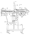
(1)供給装置本体と、
その供給装置本体に、部品供給対象装置に近接した供給位置と部品供給対象装置から離れた退避位置とに水平方向に移動可能に支持された可動部材と、
その可動部材に着脱可能に支持されるとともに、電子回路部品を平面状に並べて支持するトレイを複数枚水平に並べて支持可能な支持面を有する支持板と
を含むトレイ型部品供給装置。
前記特許文献1に記載のトレイ型部品供給装置においては、トレイホルダが供給装置本体に位置を固定して設けられているため、電子回路部品の補給等、トレイ型部品供給装置に対する作業を作業者がやり難い問題がある。部品装着システムにおいて部品装着ヘッドがヘッド移動装置により移動させられ、トレイ型部品供給装置から電子回路部品を取り出し、回路基板へ搬送して装着するのであるが、トレイ型部品供給装置全体が部品装着ヘッドの移動領域内に設けられており、その周辺にはヘッド移動装置等、装着装置等の構成部材があって作業をやり難いのである。
それに対し、本項のトレイ型部品供給装置においては、支持板によりトレイが複数枚支持されるため、複数種類あるいは多数の電子回路部品を供給することができる。そして、可動部材は、電子回路部品の供給時には供給位置に位置させられ、作業者による作業時には退避位置に位置させられる。電子回路部品を供給するため、供給位置は部品供給対象装置の作動領域内にあるが、退避位置は作動領域外に設定することができ、トレイの補充,交換等による電子回路部品の補給作業や段取替え等の作業を部品供給対象装置によって妨げられることなく、容易にかつ安全に行うことができる。また、支持板が可動部材に対して着脱可能であるため、支持板ごとトレイを交換し、支持板単位で電子回路部品の補給や段取替えを行うことができるが、この作業も容易であり、部品補給作業等をより容易にかつ迅速に行うことができる。
なお、本項のトレイ型部品供給装置において、支持板を移動不能な固定支持板とすることや、支持板を着脱不能にすることも可能である。
(2)前記可動部材を前記供給位置と前記退避位置とに移動させるアクチュエータであって、位置制御機能を有さないアクチュエータを含む(1)項に記載のトレイ型部品供給装置
。
本項のアクチュエータは、電動モータでもよく、流体圧シリンダでもよい。
位置制御機能を有さないアクチュエータは安価であり、装置コストを低減させることができる。位置制御機能を有さないアクチュエータであっても、可動部材を減速させて停止させることができる。例えば、アクチュエータが電動モータである場合、供給位置と退避位置との各手前にそれぞれ、可動部材を検出するセンサを設け、可動部材が検出されたならば、供給電流が予め設定されたパターンで減少させられ、減速させられるようにするのである。また、アクチュエータが流体圧シリンダである場合、作動流体は気体でも液体でもよく、ピストンのストロークエンド近傍への移動を検出するセンサを設け、そのセンサの検出に応じて絞り装置によって作動流体の流量が絞られるようにしたり、流体圧シリンダ自体をストロークエンド近傍において流体の流入量あるいは流出量を絞る絞り装置を備えたものとしたりすることにより、可動部材を減速させて停止させることができる。いずれにしても、最終的には可動部材がトッパに当接して移動限度が規定されるとともに、移動限度への到達がセンサにより検出され、電流や圧力流体の供給が停止されるようにすることが望ましい。
(3)前記供給位置の下方において、空になったトレイを受けるトレイ受けが前記供給装置本体に保持された(1)項または(2)項に記載のトレイ型部品供給装置。
トレイ型部品供給装置において可動部材の移動経路の下方には、空きスペースを設けることができるとともに、可動部材が供給位置と退避位置とに移動させられることにより、いずれか一方の位置に位置する状態において他方の位置に対応する空間が開放される。したがって、この空きスペースにトレイ受けを設け、空トレイを受けさせることができる。
トレイ受けは供給位置の下方と退避位置の下方とのいずれに設けてもよいが、供給位置の下方に設ける方が部品供給対象装置に近く、例えば、部品供給対象装置に空トレイ廃棄装置ないしトレイ除去装置を設ける場合に便利である。トレイ受けを供給位置の下方に設ければ、電子回路部品の供給中は空のトレイをトレイ受けに受けさせることはできないが、可動部材および支持板を短時間供給位置から退避させることは容易であり、トレイ受けの上方を開放して空のトレイを廃棄することができる。また、トレイが空になれば、電子回路部品の補充が必要である場合があり、その補充中に空のトレイを廃棄させれば時間の浪費を回避することができる。
このように供給位置の下方にトレイ受けを設ければ、部品供給対象装置のトレイ型部品供給装置が設けられる部分以外の部分にトレイ受けを設けなくて済み、部品供給対象装置をコンパクトに構成することができる。
なお、空トレイが生じる毎にトレイ受けに受けさせてもよく、空トレイが複数枚、溜まった場合にまとめて受けさせてもよい。
トレイ受けは、(4)項に記載のトレイ型部品供給装置におけるようにトレイシュートで
もよく、あるいはトレイ収拾箱でもよい。
(4)前記トレイ受けが、上部開口においてトレイを受け、下部開口から排出するトレイシュートである(3)項に記載のトレイ型部品供給装置。
例えば、空トレイを水平方向において供給位置とは異なる位置に排出することができ、排出の自由度が高い。
(5)トレイシュートの上部開口が前記支持板の前記支持面以上の幅を有する(4)項に記
載のトレイ型部品供給装置。
空になったトレイを、支持板の支持面に平行な方向における位置を変えることなく、支持板から持ち上げられたままの位置でトレイ受け上に落下させることができ、空のトレイを上部開口上へ移動させなくて済み、トレイ廃棄動作ないしトレイ除去動作が簡易になる。また、複数枚のトレイの各々について、トレイシュートへの水平方向における投入位置を異ならせることができ、トレイシュートの出口も広くすることにより、トレイシュートから放出される空のトレイを収容する空トレイ収容器内の特定部分に、空のトレイが重なり合って盛り上がってしまうことを回避することができる。
(6)前記下部開口の面積が前記上部開口の面積より小さい(4)項または(5)項に記載のトレイ型部品供給装置。
上部開口と下部開口とは、例えば、水平面内において可動部材の移動方向と平行な方向
と、それと直交する方向との少なくとも一方において寸法を異ならされることにより、下部開口の面積が上部開口の面積より小さくされる。
本項に記載のトレイ型部品供給装置においては、トレイをトレイシュートに広い上部開口から容易に投入することができるとともに、小形の空トレイ収容器に収容させることができる。
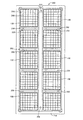
(7)前記支持面上において、前記トレイを複数枚重ねた状態で位置決めするトレイ位置決め装置を含む(1)項ないし(6)項のいずれかに記載のトレイ型部品供給装置。
互いに重ねられる複数枚のトレイは、同じ種類のトレイでもよく、異なる種類のトレイでもよい。種類が異なるトレイは、例えば、収容する電子回路部品の種類や電子回路部品の収容数を異にする。
トレイを複数枚重ねれば、支持板を大きいものとすることなく、電子回路部品の供給数を増やすことができる。トレイ位置決め装置によって位置決めされることにより、重ねられたいずれのトレイについても支持板上における位置が決まり、トレイからの電子回路部品の取出しを正確に行うことができる。
トレイが複数枚重ねられる場合、支持板に支持させるトレイの枚数を多くすることができるが、空トレイが多く生じるため、トレイ受けがあれば便利であり、本項が(3)項に従
属する態様では、トレイの枚数を増やしつつ、トレイ受けの配置に専用のスペースを必要としないトレイ型部品供給装置が得られる。
本項の特徴は(1)項ないし(6)項の各々に記載の特徴とは別個に採用することも可能である。
(8)前記トレイ位置決め装置が、
底面の少なくとも一部に永久磁石を備えた位置決め部材と、
前記支持板の前記支持面の少なくとも一部に沿って配設された磁性部と
を含む(7)項に記載のトレイ型部品供給装置。
トレイは支持板の支持面により直接支持されてもよく、トレイ収容器に収容され、そのトレイ収容器が支持面により支持されてもよい。いずれの場合にも、トレイは1枚ずつ支持されてもよく、複数枚重ねられた状態で支持されてもよい。トレイ収容器が本項のトレイ位置決め装置により支持面上において位置決めされてもよい。トレイ収容器をトレイと見なし、トレイ位置決め装置により位置決めされると考えることもでき、トレイ収容器を介してトレイがトレイ位置決め装置により位置決めされると考えることもできる。
トレイが複数枚重ねられた状態で支持される場合、支持面により直接支持されるのであれば、全部のトレイが本位置決め部材によって位置決めされるようにしてもよく、トレイに位置決め部を設け、複数のトレイが重ねられることにより互いに水平方向に位置決めされ、少なくとも一番下のトレイが本位置決め部材により位置決めされるようにしてもよい。この場合、トレイ位置決め装置は上方のトレイを間接的に位置決めすることとなる。また、トレイが複数枚重ねられるとともに、トレイ収容器に収容される場合も同様であり、複数枚のトレイ全部がトレイ収容器によって位置決めされるようにしてもよく、一番下のトレイがトレイ収容器によって位置決めされるようにしてもよい。複数枚のトレイ全部がトレイ収容器によって位置決めされる場合、トレイに位置決め部を設けることが不可欠ではなくなる。トレイ収容器が位置決め部材および磁性部と共にトレイ位置決め装置を構成すると考えることもできる。
また、支持面には、トレイ収容器に収容されて支持板上に支持されるトレイと、直接支持されるトレイとの両方が載置されてもよく、トレイ収容器に収容されるトレイのみが載置されてもよく、直接支持されるトレイのみが載置されてもよい。
磁性部は、支持面の少なくとも一部を構成する状態で配設されてもよく、例えば、非磁性材料製の薄い板材等の支持面構成部材の下に配設されてもよい。磁性部は、支持面の位置決め部材の固定に必要な箇所に磁気吸引力が生じさせられる状態で配設されればよいのである。
位置決め部材を磁力によって支持板に固定するようにすれば、位置決め部材の支持板に対する取付け,取外しを容易に行うことができ、位置決め作業を容易に行うことができる
。また、トレイの寸法,支持板により支持される数等の違いに容易に対応することができる。
(9)前記可動部材を前記供給位置と前記退避位置とに移動させる可動部材駆動装置と、
前記供給装置本体に、前記退避位置にある前記支持板を上方から覆う閉位置と、その退避位置にある支持板の上方を開放する開位置とに移動可能に取り付けられたカバーと、
そのカバーの開閉動作を検出する開閉検出装置と、
その開閉検出装置の検出結果に基づいて前記可動部材駆動装置の作動を制御する可動部材移動制御装置と
を含む(1)項ないし(8)項のいずれかに記載のトレイ型部品供給装置。
カバーが設けられていれば、例えば、可動部材の移動中、カバーが閉位置に位置させられることにより、作業者が可動部材や支持板に接触する恐れがない。また、電子回路部品の供給が行われない状態において可動部材が退避位置に位置させられるとき、カバーが閉位置において支持板を覆うことにより、電子回路部品に塵埃等がかかることが防止される。
本項のトレイ型部品供給装置においては、カバーの開閉動作を利用して可動部材駆動装置を作動させ、可動部材を移動させることができる。
本項の特徴は(1)項ないし(8)項の各々に記載の特徴とは別個に採用することも可能である。
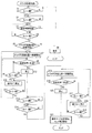
(10)前記可動部材移動制御装置が、
前記開閉検出装置が、前記カバーが前記閉位置から前記開位置に向かって第1設定量以下移動したのち再び閉位置へ戻ったことを検出するのに応じて、前記可動部材駆動装置に前記可動部材を前記供給位置から前記退避位置への移動を開始させる退避開始制御部と、
前記開閉検出装置が、前記カバーが前記開位置から前記閉位置へ移動したことを検出するのに応じて、前記可動部材駆動装置に前記可動部材を前記退避位置から前記供給位置への移動を開始させる前進開始制御部と、
前記開閉検出装置が、前記可動部材駆動装置の作動中に前記カバーが前記閉位置から開位置に向かって操作されたことを検出するのに応じて、前記可動部材駆動装置の作動を停止させる移動停止制御部と
の少なくとも1つを含む(9)項に記載のトレイ型部品供給装置。
移動停止制御部を含む場合、例えば、カバーが開かれたままの状態において可動部材が移動することが回避され、安全性が向上する。
(11)前記移動停止制御部が、前記開閉検出装置がカバーが前記閉位置から第2設定量より多く開かれたことを検出するのに応じて前記可動部材駆動装置の作動を停止させるものである(10)項に記載のトレイ型部品供給装置。
カバーが全開させられなくても、可動部材の移動中にカバーが閉位置から第2設定量より多く開かれれば、可動部材を停止させることができる。第1設定量と第2設定量とは互いに異ならせてもよく、同じにしてもよい。
(12)前記移動停止制御部が前記可動部材駆動装置の作動を予め定められた減速パターンに従って減速させ、停止させるものである(10)項または(11)項に記載のトレイ型部品供給装置。
減速パターンは可動部材を滑らかに減速させて停止させるパターンとされる。この際の減速パターンは、可動部材を供給位置および退避位置においてそれぞれ停止させる場合の減速パターンと同じでもよく、異ならせ、減速度が小さくなるようにしてもよい。可動部材を減速させて停止させることにより、移動中にカバーが開かれても可動部材が急に停止させられることがなく、停止時の衝撃により電子回路部品がトレイから飛び出したりすることが回避される。
(13)前記開閉検出装置が、前記カバーが前記閉位置にある状態と、閉位置にない状態とにおいて異なる信号を出力する閉検知装置と、その閉検知装置がカバーが閉位置にない状態を検知している時間を計測するタイマとを含む(9)項ないし(12)項のいずれかに記載
のトレイ型部品供給装置。
カバーが閉位置にない状態における時間の長さに基づいて、可動部材の移動停止や移動開始を指示することができる。例えば、閉位置にない状態の継続時間が設定時間(第1設定時間)以下で再び閉位置にある状態に復帰した場合は、カバーが上記第1設定量以下開かれて再び閉じられたとし、閉位置にない状態が第2設定時間より長く続けば、カバーが上記第2設定量より多く開かれたとするのである。
本項の特徴は(9)項ないし(12)項の各々に記載の特徴とは別個に採用することも可能で
ある。
(14)前記開閉検出装置が、前記カバーが前記閉位置にあることを検知する閉検知装置と、前記カバーが第1設定量より多く前記開位置に向かって移動し、開位置にあることを検知する開検知装置と、前記カバーが前記第1設定量より小さい第2設定量より多いが第1設定量以下である量以上開位置に向かって移動したことを検知する中間検知装置とを含む(9)項ないし(12)項のいずれかに記載のトレイ型部品供給装置。
中間検知装置による検知に基づいて、例えば、可動部材の移動開始を指示することができる。
本項の特徴は(9)項ないし(13)項の各々に記載の特徴とは別個に採用することも可能で
ある。
(15)前記供給装置本体が3個以上の車輪を備えて移動可能な台車であり、かつ、その台車を少なくとも前記支持板を部品供給対象装置に対して位置決めした状態で部品供給対象装置に連結する連結装置を含む(1)項ないし(14)項のいずれかに記載のトレイ型部品供
給装置。
少なくとも支持板が部品供給対象装置に対して位置決めされれば、支持板に支持されたトレイも位置決めされ、トレイにより支持される電子回路部品の位置がわかる。支持板の他、可動部材,供給装置本体も部品供給対象装置に対して位置決めされてもよい。
本トレイ型部品供給装置は、移動させることができる。そのため、例えば、トレイ型部品供給装置を部品供給対象装置に連結される場所とは異なる場所へ移動させることができ、広いスペースや作業に便利なスペースにおいてメンテナンスを行ったり、電子回路部品の補給や段取替え等の作業を行うことができる。トレイ型部品供給装置自体を交換することにより、電子回路部品の補給や段取替えを行うこともできる。この場合、次に電子回路部品の供給に使用されるトレイ型部品供給装置を準備しておいて、迅速に交換し、段取替えを行うのである。
本項の特徴は(1)項ないし(14)項の各々に記載の特徴とは別個に採用することも可能で
ある。
(16)前記連結装置が、鉛直方向に延びる位置決め凹部と位置決め突部との少なくとも一方であって合計で2つの位置決め部を備え、鉛直方向に昇降可能な昇降部材を含む(15)項に記載のトレイ型部品供給装置。
昇降部材の上昇により、位置決め凹部と位置決め突部とが嵌合されて台車が部品供給対象装置に連結され、昇降部材の下降により位置決め凹部と位置決め突部とが離脱させられて連結が解除される。
(17)(1)項ないし(14)項のいずれかに記載の部品供給装置と、
その部品供給装置から供給される電子回路部品を回路基板に装着する部品装着機と
を含む部品装着システムであって、
前記部品装着機が、
装着機本体と、
その装着機本体上に設けられ、前記回路基板を保持する基板保持装置と、
前記部品供給装置から電子回路部品を受け取り、前記基板保持装置に保持された回路基板に装着する装着装置と
を含む部品装着システム。
(18)前記供給装置本体が3個以上の車輪を備えて移動可能な台車であり、かつ、その台車を少なくとも前記支持板を前記部品装着機に対して位置決めした状態で部品装着機に連結する連結装置を含む(17)項に記載の部品装着システム。
台車が部品装着機に連結され、移動不能であっても、支持板は可動部材に対して着脱可能であり、台車を部品装着機に連結したままの状態で支持板を交換し、供給する電子回路部品を回路基板に合わせて交換し、段取替えを行うことができる。
本項の特徴は(1)項ないし(16)項の各々に記載の特徴とは別個に採用することも可能で
ある。
(19)前記連結装置が、
鉛直方向に延びる位置決め凹部と位置決め突部との少なくとも一方であって合計で2つの第1位置決め部を備え、前記部品供給装置に設けられた鉛直方向に昇降可能な昇降部材と、
前記部品装着機に設けられ、前記2つの第1位置決め部と嵌合する2つの第2位置決め部と、
前記部品供給装置と前記部品装着機とのいずれかに設けられ、前記昇降部材を昇降させることにより前記第1位置決め部と前記第2位置決め部とを嵌合,離脱させる昇降駆動装置と
を含む(18)項に記載の部品装着システム。
(20)第1部品供給装置としての前記部品供給装置とは別の第2部品供給装置が、第1部品供給装置から水平方向に外れた位置に設けられた(17)項ないし(19)項のいずれかに記載の部品装着システム。
第2部品供給装置は、例えば、第1部品供給装置と同様のトレイ型部品供給装置とされ、あるいは電子回路部品を一列に並べて1個ずつ順次供給するフィーダ型部品供給装置とされる。いずれにしても、例えば、第2部品供給装置が電子回路部品を供給している間に第1部品供給装置について可動部材を退避位置へ移動させ、電子回路部品の補給や段取替えを行うことができる。
前記特許文献1に記載のトレイ型部品供給装置にはフィーダ型部品供給装置が併設されており、フィーダ型部品供給装置が電子回路部品を供給している間にトレイ型部品供給装置について電子回路部品の補給等の作業を行うことが可能であるが、このトレイ型部品供給装置のトレイホルダは、装着装置の作動領域内に位置を固定して設けられているため、作業がやり難い。それに対し、本項の部品装着システムにおいては、トレイ型部品供給装置が可動部材の退避位置への移動により支持板を退避させ、装着装置の作動領域外へ退避させることができるため、第2部品供給装置による電子回路部品の供給中に作業を行うことにより、電子回路部品の装着を中断して装着能率を低下させることなく、電子回路部品の補給等の作業を行うことができる上、作業を安全な場所で容易に行うことができる。
(21)前記支持面上において前記トレイを複数枚重ねた状態で位置決めするトレイ位置決め装置を含み、かつ、前記部品装着機が、前記複数枚重ねられたトレイのうち最上のものの高さを検出するトレイ高さ検出装置を含む(17)項ないし(20)項のいずれかに記載の部品装着システム。
トレイが複数枚重ねられた状態で位置決めされる場合、最上のトレイの高さは、トレイが空になって除かれる毎に変わる。トレイの厚さ(高さ方向の寸法)が予めわかっており、重ねられたトレイの枚数が既知であれば、それらから最上のトレイの高さを取得することができるが、誤差が生じる。また、トレイの厚さや積み重ね枚数が既知であるとは限らない。それに対し、トレイ高さ検出装置によって最上のトレイの高さを検出すれば、正確な高さが得られ、装着装置が電子回路部品を適切に保持することができる。
最上のトレイの高さは、トレイが空になって除かれる毎に検出されるようにしてもよく、設定枚数毎に検出されるようにしてもよい。
本項の特徴は(1)項ないし(20)項の各々に記載の特徴とは別個に採用することも可能で
ある。
(22)前記トレイ高さ検出装置が、
上下方向に延びる嵌合穴を備えた検出装置本体と、
その検出装置本体を昇降させる検出装置本体昇降装置と、
前記検出装置本体の高さを検出する本体高さ検出装置と、
前記検出装置本体の前記嵌合穴に摺動可能にかつ予め定められた突出位置に向かって付勢された状態で嵌合された検出子と、
その検出子が前記突出位置から設定量後退したことを検出する後退検出装置と
を含む(21)項に記載の部品装着システム。
検出装置本体の高さ位置と、高さ検出ヘッドの上下方向寸法(例えば、検出子が突出位置から設定量後退した状態における検出装置本体の後端から検出子の先端までの寸法)とに基づいて、トレイの高さを取得することができる。
(23)前記後退検出装置が、
前記検出子に形成され、その検出子の外周面のその検出子が前記突出位置にある状態では前記検出装置本体から外部へ露出した状態となる部分に形成された開口と、前記嵌
合穴の内部空間とを結ぶ空気吸引通路と、
前記嵌合穴の内部空間に大気圧とは異なる圧力を印加する圧力印加装置と、
前記嵌合穴の内部空間内の圧力が設定圧以上である状態と設定圧より低い状態とで異なる信号を発する圧力検出装置と
を含む(22)項に記載の部品装着システム。
圧力印加装置は、大気圧より低い負圧を印加するものでも、大気圧より高い正圧を印加するものでもよい。
検出子が検出装置本体に対して相対移動し、その外周面に形成された開口の少なくとも一部が検出装置本体によって塞がれ、開口面積が減少すれば、内部空間の圧力が変化し、圧力検出装置が発する信号が変わることにより検出子の後退が検出される。
例えば、装着装置が電子回路部品を負圧によって吸着する吸着ノズルを備える場合、吸着ノズルに供給される負圧を利用してトレイの高さを検出することができる。また、吸着ノズル昇降装置と検出装置本体昇降装置とを兼用することが可能であり、装置コストの増大を抑制することが可能である。
(24)前記供給位置の下方に、空になったトレイを受けるトレイ受けが前記供給装置本体に固定して設けられており、かつ、前記支持板が前記供給位置にある状態で前記空になったトレイを前記支持面から持ち上げ、支持板が前記供給位置から移動した後に前記トレイ受け上に落下させる空トレイ廃棄装置を含む(17)項ないし(23)項のいずれかに記載の部品装着システム。
本項の特徴は(1)項ないし(23)項の各々に記載の特徴とは別個に採用することも可能で
ある。
(25)前記空トレイ廃棄装置が前記部品装着機に設けられた(24)項に記載の部品装着システム。
(26)前記部品装着機の前記装着装置が前記電子回路部品を負圧により吸着する部品吸着ヘッドを含み、前記空トレイ廃棄装置が、前記空になったトレイを負圧により吸着するトレイ吸着ヘッドを含む(25)項に記載の部品装着システム。
本項の特徴は(1)項ないし(25)項の各々に記載の特徴とは別個に採用することも可能で
ある。
(27)前記装着装置が、前記部品吸着ヘッドと前記トレイ吸着ヘッドとを選択的に保持するヘッド保持装置を含む(26)項に記載の部品装着システム。
(28)電子回路部品を平面状に並べて支持するトレイを複数枚、一平面状に並べて支持可能な支持面を有する支持板と、
前記支持面の任意の位置に取付け,取外し可能に取り付けられ、前記トレイを、支持面に平行な一平面内において互いに直交する2方向の少なくとも一方について位置決めする位置決め部材と、
その位置決め部材を前記支持面に取り付ける取付装置と
を含むトレイ支持装置。
取付装置は、例えば、磁性部および永久磁石を含み、位置決め部材を磁力により支持面に固定するものとされる。
支持面には、目盛等、位置決め部材の取付位置を指示する位置決め部材取付指示部を設
けることが望ましい。また、支持板は、電子回路部品が供給される装置の本体や可動部材等に位置決めして取り付け、取り外される位置決め部ないし取付部を含むものとしてもよい。
本項のトレイ支持装置が部品装着システムに設けられる場合、支持板は部品装着システムに着脱可能に設けられてもよく、固定されて設けられてもよい。
以上(1)項ないし(28)項の各々に記載された特徴は下記(29)項ないし(40)項の各々に記
載された特徴と組み合わせて採用することが可能である。
(29)回路基板を保持する基板保持装置と、
前記電子回路部品を平面状に並べて支持するトレイを複数枚積み重ねた状態で支持する支持板と、
前記トレイから電子回路部品を受け取って、前記基板保持装置に保持された回路基板に装着する装着装置と、
前記積み重ねられたトレイのうち一番上のものの高さを検出するトレイ高さ検出装置と、
前記トレイを保持するトレイ保持ヘッドを備え、そのトレイ保持ヘッドにより、前記トレイ高さ検出装置から供給される高さ情報に基づいて、前記積み重ねられたトレイのうち一番上のものを保持して取り除くトレイ除去装置と
を含む部品装着システム。
上記のように、トレイを複数枚積み重ねた状態で支持板に支持させれば、支持板の限られた支持面上に多数のトレイを載置することができる。装着装置は、複数枚積み重ねられたトレイの一番上のものから電子回路部品を受け取り、一番上のトレイが空になれば、一番上のトレイがトレイ除去装置により除去され、二番目のトレイからの電子回路部品の受取りが可能とされる。一番上のトレイの高さは、重ねられる枚数によって変わる。そこで、トレイ高さ検出装置により一番上のトレイの高さが検出され、その情報がトレイ除去装置に供給される。トレイ除去装置はこの高さ情報に基づいて作動するため、迅速かつ確実に一番上のトレイを保持して除去することができ、部品供給の中断時間をできる限り短くしつつ、多数の電子回路部品のトレイからの供給が可能になる。
本項におけるトレイ除去装置と前記(24)項ないし(26)項に記載の空トレイ廃棄装置とは、積み重ねられたトレイの一番上のものを保持して二番目以降のトレイ上方から除去するものである点において共通している。しかし、空トレイ廃棄装置は、空になったトレイを廃棄することに重点が置かれているのに対し、トレイ除去装置は一番上のトレイの除去に重点が置かれている。トレイ除去装置は、空トレイ廃棄装置としても使用し得るものであるが、除去するトレイは必ずしも空のトレイには限定されず、未だ電子回路部品を収容しているものが除去されてもよく、除去されたトレイをどこへ運んで開放するかも限定されないのである。
支持板は、部品装着システムに着脱可能に設けられてもよく、固定されて設けられてもよい。
なお、本態様の部品装着システムにおいてトレイ高さ検出装置を省略することも可能である。
(30)前記トレイ除去装置が、
前記トレイ保持ヘッドを保持するヘッド保持装置と、
そのヘッド保持装置を、少なくとも、前記支持板の前記トレイを支持する支持面に平行な方向に移動させるヘッド移動装置と
を含む(29)項に記載の部品装着システム。
本項の特徴によれば、トレイ除去装置を容易に構成することができる。
前記(24)項ないし(27)項の各々に記載の特徴は本項のトレイ除去装置にも適用可能である。
(31)前記装着装置が、
前記電子回路部品を保持する部品保持ヘッドと、
その部品保持ヘッドと前記トレイ保持ヘッドとを選択的に保持するヘッド保持装置と、
そのヘッド保持装置を、少なくとも、前記支持板の前記トレイを支持する支持面に平行な方向に移動させるヘッド移動装置と
を含む(29)項または(30)項に記載の部品装着システム。
装着装置の大部分をトレイ除去装置として利用することができ、トレイ除去装置を安価に構成することができる。
(32)前記部品保持ヘッドを収納する部品保持ヘッド収納装置と前記トレイ保持ヘッドを収納するトレイ保持ヘッド収納装置とを含む(31)項に記載の部品装着システム。
部品保持ヘッド収納装置とトレイ保持ヘッド収納装置とを設ければ、部品保持ヘッドやトレイ保持ヘッドが不要な場合には、ヘッド保持装置から外して収納しておくことができる。特に、複数の収納部を備えたものとすれば、複数の部品保持ヘッドやトレイ保持ヘッド(種類は同じでもよいが、異なるものとすることが望ましい)を収納させておき、選択的に使用することが可能となる。
(33)前記部品保持ヘッド収納装置と前記トレイ保持ヘッド収納装置とが、部品保持ヘッド収納部とトレイ保持ヘッド収納部とを備えて一体的に構成された(32)項に記載の部品装着システム。
部品保持ヘッド収納装置とトレイ保持ヘッド収納装置とをそれぞれ独立に構成することも可能であるが、一体的に構成する方が装置を安価に製造し得る場合が多い。特に、部品保持ヘッドとトレイ保持ヘッドとの本体部材を共通にする等により、被収納部の外形や寸法を同じにすれば、部品保持ヘッド収納部をトレイ保持ヘッド収納部として使用したり、逆にトレイ保持ヘッド収納部を部品保持ヘッド収納部として使用したりすることが可能となる。また、両装置を独立に構成する場合に比較して、ヘッド保持装置の最大可動範囲が狭くて済むことが多く、また、部品保持ヘッドの収納,取出しとトレイ保持ヘッドの収納,取出しとのためのヘッド移動装置の運動がほぼ同じにできる点でも有利である。
(34)前記支持板が前記トレイを横に並べて支持する大きさの支持面を備えた(29)項ないし(33)項のいずれかに記載の部品装着システム。
支持板がトレイを横に並べて支持し得るものである場合には、複数種類の電子回路部品をトレイから供給することが容易となる。横にならべて載置されるトレイがすべて積み重ねられることは不可欠ではないが、積み重ねられる場合には、トレイから供給可能な電子回路部品の個数と種類とが共に多くでき、特に有利である。横に並べられる数は多いほどよく、3つ以上が望ましい。
(35)前記支持板の前記トレイを支持する支持面の任意の位置に取付け,取外し可能に取り付けられ、前記トレイを、支持面に平行な一平面内において互いに直交する2方向の少なくとも一方について位置決めする位置決め部材と、
その位置決め部材を前記支持面に取り付ける取付装置と
を含む(29)項ないし(34)項のいずれかに記載の部品装着システム。
前記 (7)項,(8)項,(28)項等の説明は本項の部品装着システムにも当てはまる。また
、本項の特徴は(29)項ないし(34)項の各々に記載の特徴とは別個に採用することも可能である。
(36)前記トレイ高さ検出装置が、前記ヘッド移動装置により前記ヘッド保持装置と共に移動させられる検出部を備えた(30)項ないし(35)項のいずれかに記載の部品装着システム。
トレイ高さ検出装置は、検出子がトレイに接触して高さを検出する接触型でも、接触しないで高さを検出する非接触型でもよい。非接触型としては、光,電気,超音波等を利用する一般的なものを採用でき、接触型としては、例えば、(38)項,(39)項等に記載のものが好適である。検出子の位置を光や電気を利用して検出するものの採用も可能である。
検出部は、ヘッド保持装置に保持されてヘッド移動装置により移動させられてもよく、ヘッド移動装置の可動部にヘッド保持装置とは別に固定的に設けられてヘッド移動装置によりヘッド保持装置と共に移動させられてもよい。
本項の特徴によれば、高さ検出装置を安価に構成することができ、特に、複数のトレイが横に並べて配置される場合に有効であり、配置がトレイの大きさに応じて変わる場合に
は一層有効である。
なお、本項および次項の特徴は(29)項ないし(35)項の各々に記載の特徴とは別個に採用することも可能である。
(37)前記装着装置が、
前記電子回路部品を保持する部品保持ヘッドと、
その部品保持ヘッドと前記トレイ保持ヘッドとを選択的に保持するヘッド保持装置と、
そのヘッド保持装置を、少なくとも、前記支持板の前記トレイを支持する支持面に平行な方向に移動させるヘッド移動装置と
を含み、前記トレイ高さ検出装置が、前記部品保持ヘッドと選択的に前記ヘッド保持装置に保持可能な高さ検出ヘッドを含む(29)項ないし(35)項のいずれかに記載の部品装着システム。
トレイ高さ検出装置を特に安価に構成することができる。
(38)前記高さ検出ヘッドが、
上下方向に延びる嵌合穴を備えた高さ検出ヘッド本体と、
その高さ検出ヘッド本体の前記嵌合穴に摺動可能にかつ予め定められた突出位置に向かって付勢された状態で嵌合された検出子と、
を含み、前記トレイ高さ検出装置が、
前記検出子が前記突出位置から設定量後退したことを検出する後退検出装置と、
前記高さ検出ヘッド本体を昇降させる高さ検出ヘッド昇降装置と、
前記高さ検出ヘッド本体の高さを検出する本体高さ検出装置と
を含む(37)項に記載の部品装着システム。
前記(22)項の説明は本項のトレイ高さ検出装置にも当てはまる。また、本項の特徴は(29)項ないし(37)項の各々に記載の特徴とは別個に採用することも可能である。
(39)前記後退検出装置が、
前記検出子に形成され、その検出子の外周面のその検出子が前記突出位置にある状態では前記高さ検出ヘッド本体から外部へ露出した状態となる部分に形成された開口と、前記嵌合穴の内部空間とを結ぶ空気吸引通路と、
前記嵌合穴の内部空間に大気圧とは異なる圧力を印加する圧力印加装置と、
前記嵌合穴の内部空間内の圧力が設定圧以上である状態と設定圧より低い状態とで異なる信号を発する圧力検出装置と
を含む(38)項に記載の部品装着システム。
前記(23)項の説明は本項の後退検出装置にも当てはまる。
(40)前記支持板を前記電子回路部品を供給する供給位置とその供給位置から退避した退避位置とに移動させる支持板移動装置を含む(29)項ないし(39)項のいずれかに記載の部品装着システム。
前記(1)項の説明は本項にも当てはまり、前記(2)項,(9)項ないし(14)項等の特徴は本
項の部品装着システムにも適用可能である。また、本項の特徴は(29)項ないし(39)項の各々に記載の特徴とは別個に採用することも可能である。
(41)前記供給位置の下方に設けられ、空になったトレイを受けるトレイ受装置を含む(40)項に記載の部品装着システム。
トレイ受装置は、落下してくるトレイを受けて案内するトレイシュートと、そのトレイシュートに案内されたトレイを受けるトレイ収容部とを含むものとすることも、落下してくるトレイを直接受けるトレイ収容部のみを備えたものとすることもできる。
前記 (3)項,(4)項の説明は本項の部品装着システムにも当てはまり、前記(5)項,(6)
項の各々に記載の特徴は本項の部品装着システムにも適用可能である。
(42)電子回路部品を一列に並べて1個ずつ順次供給するフィーダを一直線に沿って複数並べて支持可能な第1支持面を形成する1枚以上の第1支持板を備えたフィーダ型部品供給装置と、
電子回路部品を平面状に並べて支持するトレイを複数枚、前記フィーダの並び方向に平行な方向に並べて支持可能な第2支持面を形成する1枚以上の第2支持板を備えたトレイ
型部品供給装置と、
それらトレイ型部品供給装置またはフィーダ型部品供給装置から供給される電子回路部品を回路基板に装着する部品装着機と
を含む部品装着システムであって、
前記第1支持面と前記第2支持面との前記複数のフィーダの並び方向に平行な方向の寸法である幅が互いにほぼ等しくされた部品装着システム。
前記(1)項ないし(41)項の各々に記載の特徴は、本項の特徴と組み合わせて採用するこ
とが可能である。
(43)前記トレイによる電子回路部品供給領域と、前記複数のフィーダによる電子回路部品供給領域とが、少なくとも、複数のフィーダの並び方向に平行な方向に関して同じである(42)項に記載の部品装着システム。
トレイによる電子回路部品供給領域は前記第2支持面により画定され、その幅は第2支持面の幅と同じであり、フィーダによる電子回路部品供給領域は前記第1支持面により画定され、その幅は第1支持面の幅と同じであり、本項に記載の部品装着システムにおいては、トレイによる電子回路部品供給領域とフィーダによる電子回路部品供給領域とは、幅がほぼ同じである上、複数のフィーダの並び方向に平行な方向における位置も同じである。なお、第1支持面および第2支持面の全体にフィーダおよびトレイが並べられるとは限らず、電子回路部品供給領域は電子回路部品の供給が可能な最大の領域であることとなる。
本項の態様は、次項の態様や、トレイ型部品供給装置とフィーダ型部品供給装置とが部品装着機の両側に互いに対向する状態で配設される態様を含む。
第1,第2支持面の幅がほぼ等しいフィーダ型部品供給装置とトレイ型部品供給装置とを、それら部品供給装置の各部品供給領域が、少なくとも、複数のフィーダの並び方向に平行な方向に関して同じになるようにすれば、部品装着ヘッドを移動させて部品供給装置から電子回路部品を受け取らせる場合、複数のフィーダの並び方向においては同じ領域を移動することとなり、部品装着ヘッドの移動をより有効に利用することができる。
(44)前記フィーダ型部品供給装置と前記トレイ型部品供給装置とが、前記1枚以上の第1支持板および前記1枚以上の第2支持板ごと互いに交換可能である(43)項に記載の部品装着システム。
本項の部品装着システムの一態様は(46)項に記載のものであるが、これに限定されるわけではなく、例えば、部品装着機に部品供給装置取付部を設け、その部品供給装置取付部に第1支持板と第2支持板とを選択的に取り付け可能とすることもできる。
本項の部品装着システムにおいては、フィーダ型部品供給装置とトレイ型部品供給装置とが部品装着機に対して同じ側に選択的に設けられる。
本構成によれば、フィーダ型部品供給装置とトレイ型部品供給装置との交換を、個々のフィーダやトレイについて行う場合に比較して、迅速に行うことができる。
(45)前記フィーダ型部品供給装置と前記トレイ型部品供給装置との少なくとも一方が、前記1枚以上の第1支持板または前記1枚以上の第2支持板ごと他の部品供給装置と交換可能である(42)項または(43)項に記載の部品装着システム。
本項の部品装着システムには、フィーダ型部品供給装置が第1支持板ごと他のフィーダ型部品供給装置と交換可能とされる態様、トレイ型部品供給装置が第2支持板ごと他のトレイ型部品供給装置と交換可能とされる態様、フィーダ型部品供給装置とトレイ型部品供給装置とが第1支持板および第2支持板ごと互いに交換可能とされる態様の少なくとも1つが含まれる。
第1支持板または第2支持板は、支持板単位で交換されてもよく、第1支持板群または第2支持板群単位で交換されてもよい。また、第1支持板と第2支持板との少なくとも一方が台車に設けられ、台車単位で交換されてもよい。支持板単位または支持板群単位で交換される場合、部品装着機の部品供給装置取付部に対して取付け,取外しされて交換されてもよく、台車に対して取付け,取外しされて交換されてもよい。部品供給装置が支持板を複数枚備える場合、支持板1つが小さいことが多く、そのために支持板単位での交換が
容易である。また、交換が台車単位で行われれば、部品供給装置が支持板を複数枚備える場合、複数枚の支持板を一挙に交換することができ、さらに、第1支持板または第2支持板が大形あるいは大重量であるために支持板単位では交換が困難あるいは不可能な場合でも交換可能となる場合がある。
(46)前記1枚以上の第1支持板と前記1枚以上の第2支持板とがそれぞれ、3個以上の車輪を備えて移動可能な台車に設けられており、かつ、それら台車を少なくとも前記1枚以上の第1支持板あるいは1枚以上の第2支持板を前記部品装着機に対して位置決めした状態で部品装着機に連結する連結装置を含む(42)項ないし(45)項のいずれかに記載の部品装着システム。
少なくとも支持板が部品装着機に対して位置決めされれば、支持板に支持されたフィーダおよびトレイも位置決めされ、フィーダおよびトレイにより支持される電子回路部品の位置がわかる。
例えば、(15)項に記載のトレイ型部品供給装置について得られる効果と同様の効果が、本項に記載のトレイ型部品供給装置およびフィーダ型部品供給装置についても得られる。また、本項が(44)項に従属する態様では、例えば、連結装置の部品装着機側の構成要素をトレイ型部品供給装置およびフィーダ型部品供給装置について共用させることも可能になる。
(1) a supply device body;
A movable member supported on the supply device main body so as to be movable in a horizontal direction between a supply position close to the component supply target device and a retreat position away from the component supply target device;
A support plate having a support surface that is removably supported by the movable member and that can support a plurality of trays that are arranged in a plane to support the electronic circuit components horizontally.
A tray-type component supply device.
In the tray-type component supply device described in
On the other hand, in the tray-type component supply device of this section, a plurality of trays are supported by the support plate, so that a plurality of types or a large number of electronic circuit components can be supplied. The movable member is positioned at the supply position when the electronic circuit component is supplied, and is positioned at the retracted position when the operator is working. In order to supply electronic circuit components, the supply position is within the operating area of the component supply target device, but the retracted position can be set outside the operating area, and the electronic circuit parts can be replenished by refilling and replacing trays. Work such as setup change can be easily and safely performed without being hindered by the component supply target device. In addition, since the support plate can be attached to and detached from the movable member, the tray can be replaced together with the support plate, and the electronic circuit components can be replenished and replaced in units of the support plate. Parts replenishment work and the like can be performed more easily and quickly.
In the tray-type component supply device of this section, the support plate can be a non-movable fixed support plate, or the support plate can be made detachable.
(2) The tray-type component supply device according to (1), including an actuator that moves the movable member to the supply position and the retracted position and does not have a position control function.
.
The actuator of this section may be an electric motor or a fluid pressure cylinder.
An actuator that does not have a position control function is inexpensive, and the cost of the apparatus can be reduced. Even an actuator that does not have a position control function can decelerate and stop the movable member. For example, when the actuator is an electric motor, a sensor for detecting the movable member is provided in front of the supply position and the retracted position, and if the movable member is detected, the supply current decreases in a preset pattern. To be slowed down. When the actuator is a fluid pressure cylinder, the working fluid may be gas or liquid, and a sensor for detecting the movement of the piston near the stroke end is provided, and the flow rate of the working fluid is controlled by the throttling device according to the detection of the sensor. The movable member can be decelerated and stopped by restricting the fluid pressure cylinder or by providing the fluid pressure cylinder itself with a throttle device that restricts the amount of fluid inflow or outflow near the stroke end. In any case, the movable member finally comes into contact with the topper to define the movement limit, and the arrival of the movement limit is detected by the sensor so that the supply of current and pressure fluid is stopped. Is desirable.
(3) The tray-type component supply device according to (1) or (2), wherein a tray receiver that receives an empty tray is held by the supply device main body below the supply position.
In the tray-type component supply device, an empty space can be provided below the moving path of the movable member, and the movable member is moved to the supply position and the retracted position so that it is located at one of the positions. The space corresponding to the other position is opened. Therefore, a tray receiver can be provided in this empty space to receive the empty tray.
The tray receiver may be provided either below the supply position or below the retraction position, but the one provided below the supply position is closer to the component supply target device. For example, the component supply target device may include an empty tray disposal device or tray. This is convenient when a removal device is provided. If the tray receiver is provided below the supply position, an empty tray cannot be received by the tray receiver while the electronic circuit components are being supplied, but it is easy to retract the movable member and the support plate from the supply position for a short time. Yes, it is possible to dispose of an empty tray by opening the top of the tray receiver. In addition, if the tray becomes empty, it may be necessary to replenish electronic circuit components, and waste of time can be avoided if the empty tray is discarded during the replenishment.
If the tray receiver is provided below the supply position in this way, it is not necessary to provide the tray receiver in a portion other than the portion where the tray-type component supply device of the component supply target device is provided, and the component supply target device is configured compactly. be able to.
It should be noted that each time an empty tray is generated, it may be received by a tray receiver, or may be received collectively when a plurality of empty trays are collected.
The tray receiver is a tray chute as in the tray-type component supply device described in (4).
Or a tray collection box may be used.
(4) The tray-type component supply device according to (3), wherein the tray receiver is a tray chute that receives the tray at the upper opening and discharges it from the lower opening.
For example, the empty tray can be discharged to a position different from the supply position in the horizontal direction, and the degree of freedom of discharge is high.
(5) The upper opening of the tray chute has a width larger than that of the support surface of the support plate.
A tray-type component supply device.
The emptied tray can be dropped onto the tray receiver in a position where it is lifted from the support plate without changing its position in the direction parallel to the support surface of the support plate. The tray discarding operation or tray removing operation is simplified. In addition, for each of the plurality of trays, an empty tray that accommodates empty trays discharged from the tray chute can be made different in the horizontal loading position to the tray chute, and the outlet of the tray chute is widened. It is possible to avoid that empty trays overlap and rise in a specific part in the container.
(6) The tray-type component supply device according to (4) or (5), wherein an area of the lower opening is smaller than an area of the upper opening.
The upper opening and the lower opening are, for example, directions parallel to the moving direction of the movable member in the horizontal plane
And, the area of the lower opening is made smaller than the area of the upper opening by making the dimensions different in at least one of the direction perpendicular to it.
In the tray-type component supply device described in this section, the tray can be easily put into the tray chute from a wide upper opening and can be accommodated in a small empty tray container.
(7) The tray-type component supply device according to any one of (1) to (6), including a tray positioning device that positions the plurality of trays in a stacked state on the support surface.
The plurality of trays stacked on each other may be the same type of trays or different types of trays. Different types of trays have different types of electronic circuit components to be accommodated and different numbers of electronic circuit components.
If a plurality of trays are stacked, the number of electronic circuit components supplied can be increased without increasing the size of the support plate. By positioning by the tray positioning device, the position of any of the stacked trays on the support plate is determined, and the electronic circuit components can be accurately taken out from the tray.
When multiple trays are stacked, the number of trays supported by the support plate can be increased.However, because there are many empty trays, it is convenient to have tray receivers, and this section follows section (3).
According to the aspect to which the present invention belongs, a tray-type component supply device that increases the number of trays and does not require a dedicated space for arranging the tray receiver can be obtained.
The feature of this section can be adopted separately from the feature described in each of the paragraphs (1) to (6).
(8) The tray positioning device is
A positioning member having a permanent magnet on at least a part of the bottom surface;
A magnetic part disposed along at least a part of the support surface of the support plate;
The tray-type component supply device according to item (7).
The tray may be directly supported by the support surface of the support plate, or may be stored in the tray container, and the tray container may be supported by the support surface. In either case, the trays may be supported one by one, or may be supported in a state where a plurality of trays are stacked. A tray container may be positioned on the support surface by the tray positioning device of this section. It can be considered that the tray container is regarded as a tray and is positioned by the tray positioning device, and the tray is positioned by the tray positioning device via the tray container.
When a plurality of trays are supported in a stacked state, all trays may be positioned by the positioning member as long as they are directly supported by the support surface. These trays may be stacked to be positioned in the horizontal direction, and at least the lowermost tray may be positioned by the positioning member. In this case, the tray positioning device indirectly positions the upper tray. The same applies to the case where a plurality of trays are stacked and accommodated in a tray container. All of the plurality of trays may be positioned by the tray container, and the lowermost tray is the tray container. You may make it position by a vessel. When all of the plurality of trays are positioned by the tray container, it is not essential to provide the positioning portion on the tray. It can also be considered that the tray container constitutes a tray positioning device together with the positioning member and the magnetic part.
Moreover, both the tray accommodated in the tray container and supported on the support plate and the tray directly supported may be placed on the support surface, and only the tray accommodated in the tray container may be placed. It may be placed, or only a tray that is directly supported may be placed.
The magnetic part may be disposed in a state of constituting at least a part of the support surface, and may be disposed, for example, under a support surface constituent member such as a thin plate made of a nonmagnetic material. The magnetic part should just be arrange | positioned in the state which a magnetic attraction force is produced in the location required for fixing of the positioning member of a support surface.
If the positioning member is fixed to the support plate by a magnetic force, the positioning member can be easily attached to and detached from the support plate, and the positioning operation can be easily performed.
. Further, it is possible to easily cope with differences in the dimensions of the tray, the number of the plates supported by the support plate, and the like.
(9) a movable member driving device that moves the movable member to the supply position and the retracted position;
A cover attached to the supply device main body so as to be movable between a closed position that covers the support plate in the retracted position from above and an open position that opens the support plate in the retracted position;
An open / close detection device for detecting the opening / closing operation of the cover;
A movable member movement control device for controlling the operation of the movable member driving device based on a detection result of the open / close detection device;
The tray-type component supply device according to any one of (1) to (8).
If the cover is provided, for example, the cover is positioned at the closed position during the movement of the movable member, so that there is no possibility that the operator contacts the movable member or the support plate. In addition, when the movable member is positioned at the retracted position when the electronic circuit component is not supplied, the cover covers the support plate at the closed position, so that the electronic circuit component is prevented from being dusted.
In the tray-type component supply device of this section, the movable member driving device can be operated using the cover opening / closing operation to move the movable member.
The features of this section can be adopted separately from the features described in each of the paragraphs (1) to (8).
(10) The movable member movement control device is
In response to detecting that the cover has moved from the closed position toward the open position by a first set amount or less and then returned to the closed position, the movable member driving device is moved to the movable member driving device. A retreat start control unit for starting movement of the member from the supply position to the retreat position;
In response to detecting that the cover has moved from the open position to the closed position, the open / close detection device starts moving the movable member from the retracted position to the supply position in the movable member driving device. A forward start control unit,
Movement for stopping the operation of the movable member driving device in response to detecting that the cover is operated from the closed position toward the open position during the operation of the movable member driving device. With stop control
The tray-type component supply device according to item (9), including at least one of the following.
When the movement stop control unit is included, for example, the movable member is prevented from moving in a state where the cover is opened, and the safety is improved.
(11) The movement stop control unit stops the operation of the movable member driving device in response to the opening / closing detection device detecting that the cover is opened more than the second set amount from the closed position. The tray-type component supply device according to (10).
Even if the cover is not fully opened, if the cover is opened more than the second set amount from the closed position during the movement of the movable member, the movable member can be stopped. The first set amount and the second set amount may be different from each other or may be the same.
(12) The tray-type component supply device according to (10) or (11), wherein the movement stop control unit decelerates and stops the operation of the movable member driving device according to a predetermined deceleration pattern.
The deceleration pattern is a pattern in which the movable member is smoothly decelerated and stopped. The deceleration pattern at this time may be the same as or different from the deceleration pattern when the movable member is stopped at the supply position and the retracted position, respectively, and the deceleration may be reduced. By decelerating and stopping the movable member, even if the cover is opened during movement, the movable member is not suddenly stopped, and electronic circuit components can be prevented from jumping out of the tray due to an impact at the time of stop. The
(13) A closing detection device that outputs different signals between the state in which the cover is in the closed position and the state in which the cover is not in the closed position, and the state in which the cover is not in the closed position. Including a timer for measuring the detected time, and any one of items (9) to (12)
Tray-type component feeder.
Based on the length of time when the cover is not in the closed position, it is possible to instruct to stop or start moving the movable member. For example, if the duration of the state not in the closed position returns to the closed position again after the set time (first set time) or less, the cover is opened below the first set amount and closed again. If the state that is not in the closed position continues longer than the second set time, the cover is opened more than the second set amount.
The features in this section can be adopted separately from the features described in each of paragraphs (9) to (12).
is there.
(14) The opening / closing detection device detects that the cover is in the closed position, and the cover is moved toward the open position more than a first set amount and is in the open position. An open detection device for detecting, and an intermediate detection device for detecting that the cover has moved toward the open position by an amount that is greater than a second set amount smaller than the first set amount but less than or equal to a first set amount. The tray-type component supply device according to any one of (9) to (12).
Based on the detection by the intermediate detection device, for example, the start of movement of the movable member can be instructed.
The features in this section can be adopted separately from the features described in each of paragraphs (9) to (13).
is there.
(15) The supply device main body is a movable carriage having three or more wheels, and the carriage is connected to the component supply target device in a state where at least the support plate is positioned with respect to the component supply target device. The tray type component supply according to any one of (1) to (14)
Feeding device.
If at least the support plate is positioned with respect to the component supply target device, the tray supported by the support plate is also positioned, and the position of the electronic circuit component supported by the tray can be known. In addition to the support plate, the movable member and the supply device main body may be positioned with respect to the component supply target device.
The tray-type component supply device can be moved. Therefore, for example, the tray-type component supply device can be moved to a location different from the location connected to the component supply target device, and maintenance can be performed in a large space or a space convenient for work, and electronic circuit components can be replenished. Work such as setup change can be performed. By replacing the tray-type component supply device itself, electronic circuit components can be replenished or replaced. In this case, a tray-type component supply device to be used next for supplying electronic circuit components is prepared, quickly replaced, and setup change is performed.
The features in this section can be adopted separately from the features described in each of paragraphs (1) to (14).
is there.
(16) The connection device includes at least one of a positioning recess and a positioning protrusion that extend in the vertical direction and includes a total of two positioning portions, and includes a lifting member that can move up and down in the vertical direction. Tray-type component feeder.
As the elevating member is raised, the positioning recess and the positioning protrusion are fitted to connect the carriage to the component supply target device, and when the elevating member is lowered, the positioning recess and the positioning protrusion are detached and the connection is released. .
(17) The component supply device according to any one of (1) to (14),
A component mounting machine for mounting electronic circuit components supplied from the component supply device on a circuit board;
A component mounting system comprising:
The component mounting machine is
The main body of the mounting machine,
A board holding device that is provided on the mounting machine body and holds the circuit board;
A mounting device for receiving an electronic circuit component from the component supply device and mounting the electronic circuit component on a circuit board held by the substrate holding device;
Component mounting system including.
(18) The supply device body is a movable carriage having three or more wheels, and the carriage is coupled to the component mounting machine in a state where at least the support plate is positioned with respect to the component mounting machine. The component mounting system according to item (17), including a coupling device.
Even if the cart is connected to the component mounting machine and cannot move, the support plate can be attached to and detached from the movable member, and the electronic device that supplies and replaces the support plate while the cart remains connected to the component mounting machine. The circuit components can be exchanged according to the circuit board and the setup can be changed.
The features in this section can be adopted separately from the features described in each of paragraphs (1) to (16).
is there.
(19) The coupling device is
An elevating member that is at least one of a positioning recess and a positioning protrusion extending in the vertical direction and includes a total of two first positioning units, and is capable of moving up and down in the vertical direction provided in the component supply device;
Two second positioning portions provided in the component mounting machine and fitted with the two first positioning portions;
An elevating drive device that is provided in either the component supply device or the component mounting machine, and causes the first positioning portion and the second positioning portion to be engaged and disengaged by elevating the elevating member;
The component mounting system according to item (18).
(20) Item (17) to Item (19), wherein a second component supply device different from the component supply device as the first component supply device is provided at a position horizontally deviated from the first component supply device. The component mounting system according to any one of the above.
The second component supply device is, for example, a tray-type component supply device similar to the first component supply device, or a feeder-type component supply device that sequentially arranges electronic circuit components one by one. In any case, for example, while the second component supply device is supplying the electronic circuit component, the movable member of the first component supply device is moved to the retracted position, so that the electronic circuit component is replenished or replaced. it can.
The tray-type component supply device described in
(21) A tray positioning device that positions the plurality of trays in a stacked state on the support surface, and the component mounting machine detects the height of the uppermost tray among the plurality of stacked trays. The component mounting system according to any one of (17) to (20), including a tray height detection device.
When positioning with multiple trays stacked, the height of the top tray changes each time the tray is emptied and removed. If the thickness (dimension in the height direction) of the tray is known in advance and the number of stacked trays is known, the height of the uppermost tray can be obtained from them, but an error occurs. Further, the thickness of the tray and the number of stacked sheets are not always known. On the other hand, if the height of the uppermost tray is detected by the tray height detecting device, an accurate height can be obtained, and the mounting device can appropriately hold the electronic circuit component.
The height of the uppermost tray may be detected every time the tray is empty and removed, or may be detected every set number of sheets.
The features in this section can be adopted separately from the features described in paragraphs (1) to (20).
is there.
(22) The tray height detection device is
A detection device body provided with a fitting hole extending in the vertical direction;
A detection device main body lifting device for moving the detection device main body up and down;
A body height detection device for detecting the height of the detection device body;
A detector fitted in a state of being slidable in the fitting hole of the detection device main body and biased toward a predetermined protruding position;
A reverse detection device for detecting that the detector has retracted a set amount from the protruding position;
The component mounting system according to item (21).
Based on the height position of the detection device main body and the vertical dimension of the height detection head (for example, the dimension from the rear end of the detection device main body to the front end of the detection device in a state where the detection element is retracted by a set amount from the protruding position) The height of the tray can be acquired.
(23) The reverse detection device
An opening formed in a portion of the detector that is exposed to the outside from the main body of the detector when the detector on the outer peripheral surface of the detector is in the protruding position; and the fitting
An air suction passage connecting the internal space of the joint hole;
A pressure application device that applies a pressure different from atmospheric pressure to the internal space of the fitting hole;
A pressure detection device that emits different signals depending on whether the pressure in the internal space of the fitting hole is equal to or higher than the set pressure and lower than the set pressure;
The component mounting system according to item (22).
The pressure application device may apply a negative pressure lower than atmospheric pressure or may apply a positive pressure higher than atmospheric pressure.
If the detector moves relative to the detection device main body, and at least a part of the opening formed on the outer peripheral surface thereof is blocked by the detection device main body, and the opening area decreases, the pressure in the internal space changes, and the pressure The back of the detector is detected by changing the signal emitted from the detection device.
For example, when the mounting device includes a suction nozzle that sucks an electronic circuit component with a negative pressure, the height of the tray can be detected using the negative pressure supplied to the suction nozzle. Moreover, it is possible to use both the suction nozzle lifting device and the detection device main body lifting device, and it is possible to suppress an increase in device cost.
(24) A tray receiver that receives an empty tray is fixed to the main body of the supply device below the supply position, and is empty when the support plate is in the supply position. The component mounting system according to any one of (17) to (23), further comprising an empty tray discarding device that lifts the tray from the support surface and drops the support plate onto the tray receiver after moving from the supply position. .
The features in this section can be adopted separately from the features described in each of paragraphs (1) to (23).
is there.
(25) The component mounting system according to item (24), wherein the empty tray discarding device is provided in the component mounting machine.
(26) The mounting device of the component mounting machine includes a component suction head that sucks the electronic circuit component by negative pressure, and the empty tray discarding device sucks the empty tray by negative pressure. The component mounting system according to item (25).
The features in this section can be adopted separately from the features described in paragraphs (1) to (25).
is there.
(27) The component mounting system according to (26), wherein the mounting device includes a head holding device that selectively holds the component suction head and the tray suction head.
(28) A plurality of trays that support the electronic circuit components arranged in a plane, and a support plate having a support surface that can be supported in a plane.
A positioning member that is removably attached to an arbitrary position of the support surface, and positions the tray in at least one of two directions orthogonal to each other in a plane parallel to the support surface;
An attachment device for attaching the positioning member to the support surface;
A tray support device comprising:
The attachment device includes, for example, a magnetic part and a permanent magnet, and fixes the positioning member to the support surface by a magnetic force.
The support surface is provided with a positioning member mounting instruction section that indicates the mounting position of the positioning member, such as a scale.
It is desirable to The support plate may include a positioning portion or a mounting portion that is positioned and attached to and removed from the main body or movable member of the apparatus to which the electronic circuit component is supplied.
When the tray support device of this section is provided in the component mounting system, the support plate may be detachably provided in the component mounting system or may be fixedly provided.
The characteristics described in each of items (1) to (28) above are described in each of items (29) to (40) below.
It can be used in combination with the listed features.
(29) a substrate holding device for holding a circuit board;
A support plate that supports a plurality of stacked trays that support the electronic circuit components arranged in a plane; and
A mounting device for receiving an electronic circuit component from the tray and mounting the electronic circuit component on a circuit board held by the substrate holding device;
A tray height detection device for detecting the height of the top of the stacked trays;
A tray holding head for holding the tray, and the tray holding head holds the top of the stacked trays based on height information supplied from the tray height detection device; With tray removal device to remove
Component mounting system including.
As described above, if a plurality of trays are stacked and supported by the support plate, a large number of trays can be placed on a limited support surface of the support plate. The mounting device receives electronic circuit components from the top of the stacked trays, and when the top tray is empty, the top tray is removed by the tray removal device, and the second Electronic circuit components can be received from the tray. The height of the top tray varies depending on the number of stacked sheets. Therefore, the height of the uppermost tray is detected by the tray height detecting device, and the information is supplied to the tray removing device. Since the tray removal device operates based on this height information, it can quickly and reliably hold and remove the uppermost tray, minimizing the component supply interruption time, and reducing the number of electronic circuits. Parts can be supplied from the tray.
The tray removing device in this section and the empty tray discarding device described in the items (24) to (26) hold the uppermost one of the stacked trays and remove it from above the second and subsequent trays. It is common in that it is a thing. However, the empty tray discarder is focused on discarding empty trays, while the tray remover is focused on removing the top tray. The tray removal device can also be used as an empty tray disposal device, but the tray to be removed is not necessarily limited to an empty tray, and those that still contain electronic circuit components may be removed, There is no limit to where the removed tray can be transported and opened.
The support plate may be detachably provided on the component mounting system, or may be fixedly provided.
In the component mounting system of this aspect, the tray height detection device can be omitted.
(30) The tray removing device is
A head holding device for holding the tray holding head;
A head moving device that moves the head holding device at least in a direction parallel to a support surface that supports the tray of the support plate;
The component mounting system according to item (29), including:
According to the feature of this section, the tray removing device can be easily configured.
The features described in the items (24) to (27) can be applied to the tray removing device of this item.
(31) The mounting device is
A component holding head for holding the electronic circuit component;
A head holding device that selectively holds the component holding head and the tray holding head;
A head moving device that moves the head holding device at least in a direction parallel to a support surface that supports the tray of the support plate;
The component mounting system according to (29) or (30).
Most of the mounting device can be used as a tray removing device, and the tray removing device can be configured at low cost.
(32) The component mounting system according to (31), including a component holding head storage device that stores the component holding head and a tray holding head storage device that stores the tray holding head.
If the component holding head storage device and the tray holding head storage device are provided, the component holding head and the tray holding head can be removed from the head holding device and stored when they are unnecessary. In particular, if a plurality of storage units are provided, a plurality of component holding heads and tray holding heads (which may be the same, but preferably different) are stored and selectively used. It becomes possible.
(33) The component mounting system according to (32), wherein the component holding head storage device and the tray holding head storage device are configured integrally with a component holding head storage portion and a tray holding head storage portion. .
Although the component holding head storage device and the tray holding head storage device can be configured independently of each other, it is often possible to manufacture the device at a lower cost if they are configured integrally. In particular, if the outer shape and dimensions of the receiving parts are the same, for example, by using a common body member for the part holding head and the tray holding head, the part holding head storage part can be used as a tray holding head storage part or vice versa. In addition, the tray holding head storage portion can be used as a component holding head storage portion. In addition, the maximum movable range of the head holding device is often narrower than when both devices are configured independently, and for storing and taking out the component holding head and storing and taking out the tray holding head. This is also advantageous in that the movement of the head moving device can be made substantially the same.
(34) The component mounting system according to any one of (29) to (33), wherein the support plate includes a support surface having a size to support the tray side by side.
When the support plate can support the trays side by side, it is easy to supply a plurality of types of electronic circuit components from the tray. It is not indispensable that all trays placed side by side are stacked, but when stacked, the number and types of electronic circuit components that can be supplied from the tray can be increased, which is particularly advantageous. The larger the number arranged side by side, the better.
(35) The support plate is attached to an arbitrary position of a support surface that supports the tray, and is detachably attached, and the tray is positioned in at least one of two directions orthogonal to each other within a plane parallel to the support surface. A positioning member to be
An attachment device for attaching the positioning member to the support surface;
The component mounting system according to any one of (29) to (34).
The explanations in paragraphs (7), (8), (28), etc. also apply to the component mounting system in this section. Also
The features of this section can be adopted separately from the features described in the sections (29) to (34).
(36) The component mounting system according to any one of (30) to (35), wherein the tray height detection device includes a detection unit that is moved together with the head holding device by the head moving device.
The tray height detection device may be a contact type in which the detector contacts the tray to detect the height, or a non-contact type in which the height is detected without contact. As the non-contact type, a general type utilizing light, electricity, ultrasonic waves, or the like can be adopted. As the contact type, for example, those described in the items (38), (39), etc. are preferable. It is also possible to employ a detector that detects the position of the detector using light or electricity.
The detection unit may be held by the head holding device and moved by the head moving device. The detection unit is fixedly provided separately from the head holding device and moved together with the head holding device by the head moving device. May be allowed.
According to the feature of this section, the height detection device can be configured at low cost, and is particularly effective when a plurality of trays are arranged side by side, and the arrangement changes according to the size of the tray. In
Is more effective.
The features in this section and the following section can be adopted separately from the features described in each of the sections (29) to (35).
(37) The mounting device is
A component holding head for holding the electronic circuit component;
A head holding device that selectively holds the component holding head and the tray holding head;
A head moving device that moves the head holding device at least in a direction parallel to a support surface that supports the tray of the support plate;
The component mounting according to any one of (29) to (35), wherein the tray height detecting device includes a height detecting head that can be selectively held by the head holding device together with the component holding head. system.
The tray height detection device can be configured particularly inexpensively.
(38) The height detection head is
A height detection head body with a fitting hole extending in the vertical direction;
A detector fitted in a state of being slidable in the fitting hole of the height detection head body and biased toward a predetermined protruding position;
The tray height detecting device includes:
A backward detection device for detecting that the detector has retracted a set amount from the protruding position;
A height detection head lifting device for lifting and lowering the height detection head body;
A main body height detecting device for detecting the height of the height detecting head main body;
The component mounting system according to item (37) including:
The description of the item (22) also applies to the tray height detection device of this item. Further, the feature of this section can be adopted separately from the feature described in each of the paragraphs (29) to (37).
(39) The reverse detection device
An opening formed in a portion formed in the detector and formed in a portion exposed to the outside from the height detection head main body when the detector on the outer peripheral surface of the detector is in the protruding position, and the fitting An air suction passage connecting the internal space of the hole;
A pressure application device that applies a pressure different from atmospheric pressure to the internal space of the fitting hole;
A pressure detection device that emits different signals depending on whether the pressure in the internal space of the fitting hole is equal to or higher than the set pressure and lower than the set pressure;
The component mounting system according to (38), including:
The description of the item (23) also applies to the reverse detection device of this item.
(40) The support plate moving device according to any one of (29) to (39), further including a support plate moving device that moves the support plate to a supply position for supplying the electronic circuit component and a retracted position retracted from the supply position. Component mounting system.
The explanation of paragraph (1) applies to this paragraph, and the features of paragraphs (2), (9) to (14), etc.
It can also be applied to the component mounting system of the item. Further, the feature of this section can be adopted separately from the feature described in each of the paragraphs (29) to (39).
(41) The component mounting system according to (40), including a tray receiving device that is provided below the supply position and receives an empty tray.
The tray receiving device includes a tray chute that receives and guides a falling tray, and a tray accommodating portion that receives the tray guided by the tray chute, or a tray accommodating portion that directly receives a falling tray. It can also be provided with only.
The explanations in paragraphs (3) and (4) above also apply to the component mounting system in this section, and paragraphs (5) and (6) above.
The features described in each of the items are applicable to the component mounting system described in this item.
(42) Feeder-type component supply device including one or more first support plates that form a first support surface that can support a plurality of feeders that are arranged in a line and sequentially supply one by one along a straight line. When,
A tray provided with a plurality of trays that support electronic circuit components arranged in a plane and one or more second support plates that form a second support surface that can be arranged and supported in a direction parallel to the feeder arrangement direction.
Mold component supply device;
A component mounting machine for mounting electronic circuit components supplied from the tray-type component supply device or feeder-type component supply device on a circuit board;
A component mounting system comprising:
A component mounting system in which widths of the first support surface and the second support surface, which are dimensions in a direction parallel to an arrangement direction of the plurality of feeders, are substantially equal to each other.
The features described in the items (1) to (41) are used in combination with the features of this item.
Is possible.
(43) The electronic circuit component supply region by the tray and the electronic circuit component supply region by the plurality of feeders are at least the same in the direction parallel to the arrangement direction of the plurality of feeders. Mounting system.
The electronic circuit component supply region by the tray is defined by the second support surface, and the width thereof is the same as the width of the second support surface, and the electronic circuit component supply region by the feeder is defined by the first support surface, and its width Is the same as the width of the first support surface, and in the component mounting system described in this section, the electronic circuit component supply region using the tray and the electronic circuit component supply region using the feeder have substantially the same width, and The position in the direction parallel to the direction in which the feeders are arranged is the same. Note that the feeder and the tray are not necessarily arranged on the entire first support surface and the second support surface, and the electronic circuit component supply region is the maximum region in which the electronic circuit component can be supplied.
The mode of this section includes the mode of the next section, and the mode in which the tray-type component supply device and the feeder-type component supply device are arranged on both sides of the component mounting machine so as to face each other.
A feeder-type component supply device and a tray-type component supply device in which the widths of the first and second support surfaces are substantially equal, and each component supply region of these component supply devices is at least in a direction parallel to the arrangement direction of the plurality of feeders. If it is made the same, when the component mounting head is moved to receive the electronic circuit component from the component supply device, the same region is moved in the arrangement direction of the plurality of feeders, and the component mounting head is further moved. It can be used effectively.
(44) In the item (43), the feeder-type component supply device and the tray-type component supply device are interchangeable with each other with the one or more first support plates and the one or more second support plates. Component mounting system.
One aspect of the component mounting system of this section is the one described in section (46), but is not limited thereto. For example, a component mounting apparatus mounting portion is provided in the component mounting machine, and the component supplying apparatus is mounted. The first support plate and the second support plate can be selectively attached to the part.
In the component mounting system of this section, the feeder-type component supply device and the tray-type component supply device are selectively provided on the same side with respect to the component mounting machine.
According to this configuration, replacement of the feeder-type component supply device and the tray-type component supply device can be performed quickly as compared with the case where the replacement is performed for each feeder or tray.
(45) At least one of the feeder-type component supply device and the tray-type component supply device can be replaced with another component supply device together with the one or more first support plates or the one or more second support plates. The component mounting system according to (42) or (43).
In the component mounting system of this section, the feeder-type component supply device can be replaced with another feeder-type component supply device together with the first support plate, and the tray-type component supply device can be replaced with another tray type with the second support plate. It includes at least one of a mode in which the component supply device can be exchanged and a mode in which the feeder-type component supply device and the tray-type component supply device can be exchanged with each other together with the first support plate and the second support plate.
The first support plate or the second support plate may be replaced in units of support plates, or may be replaced in units of the first support plate group or the second support plate group. In addition, at least one of the first support plate and the second support plate may be provided on the carriage, and may be exchanged in units of carriages. When exchanging in support plate units or support plate group units, they may be installed and removed from the component feeder mounting part of the component mounting machine and replaced, or they may be installed and removed from the carriage and replaced. Good. When the component supply device includes a plurality of support plates, one support plate is often small, and therefore replacement in units of support plates is required.
Easy. Further, if the replacement is performed in units of carts, when the component supply device includes a plurality of support plates, the plurality of support plates can be replaced at once, and the first support plate or the second support plate is large. Due to the shape or large weight, the support plate unit may be exchangeable even if it is difficult or impossible to exchange.
(46) The one or more first support plates and the one or more second support plates are each provided in a movable carriage provided with three or more wheels, and the carriages are at least (42) The items (42) to (45) include a connecting device that connects the one or more first support plates or the one or more second support plates to the component mounting machine in a state of being positioned with respect to the component mounting machine. The component mounting system according to any one of the above.
If at least the support plate is positioned with respect to the component mounting machine, the feeder and tray supported by the support plate are also positioned, and the position of the electronic circuit component supported by the feeder and tray can be known.
For example, the same effect as that obtained for the tray-type component supply device described in (15) can also be obtained for the tray-type component supply device and feeder-type component supply device described in this section. Further, in the aspect in which this item is dependent on the item (44), for example, the component on the component mounting machine side of the coupling device can be shared by the tray-type component supply device and the feeder-type component supply device.
以下、請求可能発明のいくつかの実施例を、図を参照しつつ詳しく説明する。なお、請求可能発明は、下記実施例の他、上記〔発明の態様〕の項に記載された態様を始めとして、当業者の知識に基づいて種々の変更を施した態様で実施することができる。 Several embodiments of the claimable invention will now be described in detail with reference to the drawings. In addition to the following examples, the claimable invention can be practiced in various modifications based on the knowledge of those skilled in the art, including the aspects described in the above [Aspect of the Invention] section. .
図1に、請求可能発明の一実施例としての部品装着システムが示されている。本部品装着システムは、トレイ型部品供給装置10,フィーダ型部品供給装置12および部品供給対象装置たる部品装着機14を備えている。部品装着機14は、装着機本体を構成するベッド20と、ベッド20上に設けられ、回路基板22を搬送する基板搬送装置24と、回路基板22を保持する基板保持装置26と、部品供給装置10,12から電子回路部品を受け取り、基板保持装置26に保持された回路基板22に装着する装着装置28とを含んでいる。基板搬送装置24は、トレイ型部品供給装置10等と共に部品装着システムを構成すると考えることもできる。
FIG. 1 shows a component mounting system as an embodiment of the claimable invention. This component mounting system includes a tray-type
本部品装着システムにおいて回路基板22は基板搬送装置24により、その電子回路部品が装着される部品装着面が水平な姿勢で搬送され、図示を省略する停止装置によって予め定められた作業位置において停止させられるとともに、ベッド20の作業位置に対応する部分に設けられた基板保持装置26により保持される。基板保持装置26は、位置を固定して設けられ、例えば、複数の支持部材を備え、回路基板22を下方から支持するとともに、クランプ部材を備え、回路基板22の搬送方向に平行な両縁をクランプする装置とされる。本部品装着システムにおいて回路基板22は、基板保持装置26により、部品装着面が水平な姿勢で支持される。基板搬送装置24による回路基板22の搬送方向(図1においては左右方向)をX軸方向とする。
In this component mounting system, the
装着装置28は、図1に示すように、ヘッドユニット30およびヘッド移動装置32を含む。ヘッド移動装置32は、ヘッドユニット30と、基板保持装置26に保持された回路基板22とを、部品装着面に平行な方向に相対移動させる相対移動装置であり、本部品装着システムにおいては、部品装着面に平行な平面内において互いに直交する2方向であって、X軸方向および水平面内においてX軸方向と直交するY軸方向にヘッドユニット30を移動させる。そのため、ヘッド移動装置32は、X軸方向移動装置34およびY軸方向移動装置36を含む。
As shown in FIG. 1, the mounting
X軸方向移動装置34は、図1に示すように、可動部材としてのX軸スライド40およびX軸スライド移動装置42を含む。X軸スライド移動装置42は、駆動源たるX軸移動用モータ44,送りねじたるボールねじ46およびナット(図示省略)を含み、X軸スライド40をX軸方向に平行な任意の位置へ移動させる。Y軸方向移動装置36は、X軸スライド40上に設けられ、可動部材としてのY軸スライド52およびY軸スライド移動装置54を含む。Y軸スライド移動装置54は、駆動源たるY軸移動用モータ56,ボールねじおよびナット(図示省略)を含み、Y軸スライド52をY軸方向に平行な任意の位置へ移動させる。X軸移動用モータ44およびY軸移動用モータ56は、電動モータの一種であり、回転角度の精度の良い制御が可能な電動回転モータの一種であるサーボモータであって、エンコーダ付きのサーボモータにより構成されている。サーボモータに代えてステップモータを用いてもよい。また、駆動源としてリニアモータを用いてもよい。
As shown in FIG. 1, the X-axis
ヘッドユニット30は、図2に示すように、Y軸スライド52上に設けられ、ヘッド移動装置32により水平面内の任意の位置へ移動させられる。ヘッドユニット30は、ヘッド保持装置60と作業ヘッドとを含み、ヘッド移動装置60は、ヘッド保持装置60を移動させ、作業ヘッドを移動させる。作業ヘッドの1つが部品保持ヘッドの一種である部品保持ヘッドたる部品装着ヘッドとしての部品吸着ヘッド62である。本装着装置28においてヘッド保持装置60は、例えば、特開平6−291490号公報に記載されているように、負圧によって部品吸着ヘッド62を吸着し、保持するものとされている。そのため、ヘッド保持装置60は、保持装置本体63と、保持装置本体63の下端部に設けられ、水平な吸着面64を備えたヘッド保持部66とを有するとともに、図示は省略するが、保持装置本体63の内部に通路が2本設けられ、それぞれ切換装置70,72を介して負圧源74に接続されている。切換装置70,72はそれぞれ、電磁制御弁を含んで構成される。部品吸着ヘッド62は、ヘッド保持装置60により保持される板状の被保持部78と、ノズル保持部80と、部品保持具としての吸着ノズル82とを含む。ヘッド保持装置60は、保持装置本体63内の2本の通路の一方に供給される負圧により、ヘッド保持部66において部品吸着ヘッド62を吸着し、他方の通路に供給される負圧は吸着ノズル82に供給され、電子回路部品を吸着させる。この他方の通路は、切換装置72を介して正圧源84にも接続され、正圧の供給により吸着ノズル82に電子回路部品を積極的に解放させる。
As shown in FIG. 2, the
本装着装置28においては、種類を異にする部品吸着ヘッド62、例えば、吸着ノズル82の吸着管の直径を異にする複数種類の部品吸着ヘッド62が用意され、装着する電子回路部品の形状,寸法等に応じて選択的にヘッド保持装置60により保持される。これら複数種類の部品吸着ヘッド62は、例えば、図1に示すように、ベッド10に基板搬送装置24の上方に位置する状態で設けられたヘッド収納装置86に収納されている。ヘッド収納装置86は、例えば、特開平6−291490号公報に記載の収納装置、あるいは未だ公開されていないが、本発明の出願人に係る特願2005−75397の明細書に記載の収納装置と同様に構成され、部品吸着ヘッド62を収納する複数の部品吸着ヘッド収納部を備えている。ヘッドユニット30はヘッド収納装置86へ移動させられ、ヘッド保持装置60が現に保持している部品吸着ヘッド62を戻すとともに、次に電子回路部品の装着に使用する部品吸着ヘッド62をヘッド保持装置60に保持させる。部品吸着ヘッドは、上記特願2005−75397の明細書に記載されているように、吸着ノズルを複数保持するものとしてもよい。
In this mounting
ヘッドユニット30は、図2に示すヘッド昇降装置88により昇降させられるとともに、ヘッド回転装置90により、その鉛直な軸線まわりに回転させられる。ヘッド昇降装置88は、Y軸スライド52上に昇降可能に設けられた昇降部材92と、駆動源たるヘッド昇降用モータ94(図12参照),ボールねじおよびナットを含む送りねじ機構95(図12参照)を備えた昇降部材駆動装置97とを含む。ヘッド保持装置60は、昇降部材9
2により軸方向に相対移動不能かつ相対回転可能に保持され、昇降部材92の昇降により昇降させられる。また、ヘッド回転装置90は、駆動源たるヘッド回転用モータ96(図12参照)と、複数の歯車を含む回転伝達装置98とを含み、ヘッドユニット30を鉛直軸線まわりに回転させる。これらヘッド昇降用モータ94およびヘッド回転用モータ96は、例えば、エンコーダ付きサーボモータにより構成され、ヘッドユニット30は、上下方向において任意の位置へ移動させられ、正逆両方向に任意の角度回転させられる。ヘッド昇降装置88は、ヘッド保持装置60を昇降させ、それに保持された作業ヘッドを昇降させる。また、ヘッド回転装置90は、ヘッド保持装置60を回転させ、それに保持された作業ヘッドを回転させる。
The
2 is held so as not to be relatively movable and relatively rotatable in the axial direction, and is raised and lowered by raising and lowering the elevating
Y軸スライド52にはまた、回路基板22に設けられた複数の基準マーク100(図1参照)を撮像する撮像装置たるマーク撮像装置102(図1参照)が設けられ、ヘッド移動装置32により水平面内の任意の位置へ移動させられる。ヘッド移動装置32は、撮像装置移動装置でもある。マーク撮像装置102は、本部品装着システムにおいては、撮像デバイスとしてのマークカメラ104と、照明装置106とを含む。マークカメラ104は、例えば、CCDカメラにより構成されるとともに面撮像装置とされ、下向きに設けられている。また、X軸スライド40には、吸着ノズル82により吸着された電子回路部品を撮像する部品撮像装置110が設けられている。部品撮像装置110は部品カメラ112(図12参照)および照明装置(図示省略)を備え、2組設けられ、トレイ型部品供給装置10により供給された電子回路部品と、フィーダ型部品供給装置12により供給された電子回路部品とがそれぞれ撮像される。
The Y-
前記部品供給装置10,12は、例えば、図1に示すように、Y軸方向に互いに隔たって、基板搬送装置24の両側に設けられる。フィーダ型部品供給装置12はトレイ型部品供給装置10から水平方向に外れた位置に設けられているのである。
For example, as shown in FIG. 1, the
トレイ型部品供給装置10は、図3に示すように、電子回路部品をトレイ130に収容して供給する装置であり、供給装置本体としての台車132を備え、部品装着機14に対して連結,切り離し可能とされている。台車132は、図3ないし図5に示すように、車体134と、車体134に取り付けられた3個以上、例えば、4個の車輪136とを備えて移動可能であり、車体134上に昇降部材138が鉛直方向に昇降可能に設けられている。昇降部材138は、複数の部材が一体的に組み付けられて成り、昇降部140と支持部141とを含む。昇降部140は、図4に示すように、概してコの字形を成す。昇降部140のコの字の底壁部分を構成する梁材142は、トレイ型部品供給装置10の幅方向(図3においては左右方向)に平行に配設され、梁材142の長手方向の両端にそれぞれ設けられた側壁部144において、車体134の幅方向に隔たった両側にそれぞれ立設された案内部材としてのガイドロッド146により昇降を案内される。
As shown in FIG. 3, the tray-type
上記一対の側壁部144にはそれぞれ、図4および図5に示すように、被案内部材たる被案内回転部材としてのガイドローラ150が2対、上下方向に距離を隔てて設けられている。各対の2個ずつのガイドローラ150はそれぞれ、外周面が回転軸線側に部分円弧状にくぼまされ、ガイドロッド146を前後両側から挟んでおり、ガイドローラ150がガイドロッド146に沿って転動し、昇降部材138の昇降が案内される。図4および図5には、昇降部材138が上昇位置に位置する状態が図示されている。昇降部材138の下降端位置は、ガイドロッド146に設けられたストッパ部材152に側壁部144が当接することにより規定される。
As shown in FIG. 4 and FIG. 5, the pair of
図3ないし図5に示すように、昇降部140の梁材142上に支持部141が設けられるとともに、支持部141上に可動部材たる一対のスライダ162および可動部材駆動装置たるスライダ駆動装置166が設けられている。支持部141は、梁材142のトレイ
型部品供給装置10の幅方向に隔たった両端部にそれぞれ、前後方向に延びる姿勢で設けられた一対の側壁168と、それら側壁168の各前端部同士を接続する前壁170と、各後端部同士を接続する後壁172とを含み、枠状を成す。
As shown in FIGS. 3 to 5, a
後壁172には取手174が設けられ、作業者が取手174を持って台車132を動かし、トレイ型部品供給装置10を移動させることができるようにされている。また、一対の側壁168の各前部にはそれぞれ、図3および図5に示すように、ブロック状の連結体ないし位置決め体178が設けられるとともに、それぞれ第1位置決め部たる位置決め凹部としての位置決め穴180が鉛直方向に延び、上方に開口する状態で設けられている。2つの位置決め穴180の一方は、長穴とされている。部品装着機14には、Y軸方向に隔たった2個所であって、基板保持装置26の両側の部分にそれぞれ、第2位置決め部たる一対の位置決め突部としての位置決めピン182が鉛直方向に設けられるとともに(図5に、基板保持装置26の一方の側に設けられた一対の位置決めピン182のうちの一方が代表的に図示されている)、それら位置決めピン182の側方にそれぞれ、昇降用シリンダ184(図12参照)が設けられ、トレイ型部品供給装置10あるいはフィーダ型部品供給装置12が配置されるようにされている。昇降用シリンダ184は、流体圧アクチュエータたる流体圧シリンダの一種であり、本部品装着機14においてはエアシリンダとされている。
A
トレイ型部品供給装置10を部品装着機14に連結する場合には、台車132が移動させられて、図5に示すように、トレイ型部品供給装置10が部品装着機14へ移動させられ、その前部(取手174が設けられた側とは反対側の部分)が部品装着機14を覆うハウジング186の下を通って部品装着機14内に進入させられるとともに、一対の位置決め穴180がそれぞれ、位置決めピン182と対向する状態において昇降用シリンダ184が作動させられ、その作動に基づいて位置決め体178が押し上げられる。ハウジング186は、部品装着機14に連結されたトレイ型部品供給装置10の部品装着機14側の部分であって、後述する供給位置に対応する部分を覆うように設けられている。ハウジング186は、基板保持装置26のY軸方向における両側においてそれぞれ、トレイ型部品供給装置10の供給位置に対応する部分を覆うように設けられている。位置決め体178が押し上げられることにより、昇降部材138が鉛直方向に上昇させられて上昇位置へ上昇させられ、一対の位置決め穴180がそれぞれ位置決めピン182に嵌合され、台車132が部品装着機14に水平方向に位置決めされて連結される。昇降部材138の上昇位置は、位置決め穴180が位置決めピン182に嵌合されるとともに、トレイ130を位置決めするL形定規(後述する)の上面の高さが、基板保持装置26に保持された回路基板22の表面ないし上面である部品装着面の高さとほぼ同じになり、マークカメラ104によるマークの撮像が回路基板22についてもL形定規についても焦点が合った状態で行われるように設定されている。マークカメラ104を昇降装置により昇降可能に設け、いずれのマークについても焦点が合わされるようにしてもよく、マークカメラ104を焦点距離の調節可能なカメラとしてもよい。
When connecting the tray-type
また、昇降用シリンダ184が台車132の連結時とは逆向きに作動させられ、その作動に基づいて昇降部材138が鉛直方向に下降し、位置決め穴180が位置決めピン182から離脱する。昇降部材138の昇降は、ガイドロッド146およびガイドローラ150を含む案内装置により案内される。本部品装着システムにおいては、一対の昇降用シリンダ184が昇降駆動装置を構成し、昇降部材138,位置決め穴180,位置決めピン182と共に連結装置を構成している。台車134は位置決め穴180および位置決めピン182の嵌合により部品装着機14に対して位置決めされた状態で連結され、トレイ130を支持する支持板は、後述するようにスライダ162により位置決めされて支持され、スライダ162および台車134を介して部品装着機14に対して位置決めされる。台車132が部品装着機14に連結された状態において、トレイ型部品供給装置10の幅方
向ないし左右方向はX軸方向に平行となり、前後方向はY軸方向に平行となる。前後方向において部品装着機14の基板保持装置26に近い側が前側であり、離れた側が後側である。
Further, the
昇降部材138の支持部141の前記一対の側壁168上にはそれぞれ、図4および図5に示すように、案内部材としてのガイドレール190が前後方向に延びる状態で設けられるとともに、それぞれに前記スライダ162が移動可能に嵌合されている。一対のスライダ162はそれぞれ、循環可能に保持したボールを介してガイドレール190に移動可能に嵌合されており、リニアガイドにより移動を案内される。一対のスライダ162はそれぞれ、一対の側壁168にそれぞれ周回可能に設けられた無端のタイミングベルト192に係止させられ、タイミングベルト192がベルト周回装置194によって周回させられることにより、前後方向に移動させられる。ベルト周回装置194は、一対の側壁168にそれぞれ回転可能に設けられ、タイミングベルト192が巻き掛けられた一対の回転巻掛部材としてのタイミングプーリ196,198と、駆動源としてのベルト周回用モータ200と、ベルト周回用モータ200の回転をタイミングプーリ196に伝達する駆動歯車202および被駆動歯車204とを含む。一対のタイミングベルト192がそれぞれ巻き掛けられた一方のタイミングプーリ196は、共通の回転軸206(図4参照)であって、被駆動歯車204が取り付けられた回転軸206に取り付けられ、一対のタイミングベルト192が同時に周回させられる。それにより、一対のスライダ162が同時に移動させられ、図5に実線で示すように、部品装着機14に近接し、トレイ130が電子回路部品を供給する供給位置と、二点鎖線で示すように部品装着機14から離れ、供給位置から退避した退避位置とに移動させられる。ベルト周回用モータ200はエンコーダ付きサーボモータにより構成され、スライダ162の移動位置および移動速度が制御される。このエンコーダは、インクリメンタルエンコーダとされている。
のエンコーダは、インクリメンタルエンコーダとされている。
As shown in FIGS. 4 and 5,
The encoder is an incremental encoder.
図3および図5に示すように、上記一対のスライダ162により支持板210が着脱可能に支持され、その支持板210により前記トレイ130が支持される。したがって、スライダ162の移動により支持板210が供給位置と退避位置とに移動させられる。スライダ駆動装置166は支持板移動装置でもある。支持板210はハニカム構造とされて軽量でありながら十分な剛性を有するものとされている。支持板210は、アルミニウム合金製のハニカム構造物を、同じくアルミニウム合金製の薄板で両側から挟んで固定したハニカム構造の本体部と、その上面に固定された磁性材料製の表層部から成っているのである。表層部は、ホワイトボードなどに使用される板材(磁性を有する樹脂合板)により構成され、後述の位置決め部材としてのL形定規270を永久磁石により固定可能であるとともに、ホワイトボードマーカによる文字やマークの書込みが可能である。
As shown in FIGS. 3 and 5, the
支持板210には、図5に示すように、その裏面に開口して位置決め部としての位置決め凹部212が一対、設けられ、それら位置決め凹部212が、一対のスライダ162にそれぞれ設けられた位置決め部としての位置決め突部214に嵌合されることにより、支持板210が一対のスライダ162に対して水平方向に位置決めされた状態で、それらスライダ162により下方から支持される。これら位置決め凹部212および位置決め突部214が支持板位置決め装置を構成している。支持板210に位置決め突部を設け、スライダ162に位置決め凹部を設けてもよく、支持板210とスライダ162とにそれぞれ、位置決め突部および位置決め凹部を1つずつ設けてもよい。位置決め凹部は、支持板210を厚さ方向に貫通する貫通穴でもよい。なお、図1においてトレイ型部品供給装置10は、台車132等は省略され、トレイ130および支持板210のみが図示されている。
As shown in FIG. 5, the
支持板210は、本トレイ型部品供給装置10においては表層部が磁性材料により作られ、その表層部により構成される支持板210の水平な支持面220は磁性材料製である
。本トレイ型部品供給装置10は、支持板210を1枚備え、その1枚の支持板210により、トレイ型部品供給装置10の支持面の全部が形成され、支持面220はトレイ型部品供給装置10の全支持面を構成する。トレイ型部品供給装置10による部品供給領域は、トレイ型部品供給装置10の支持面、ここでは支持面220により画定され、その幅は支持面220の幅と同じである。支持面220には、部品供給装置10の幅方向に平行に延びるガイドバー222が設けられ、案内部を構成している。ガイドバー222は、支持面220に直角な位置決め面224を有する。また、ガイドバー222の支持面220に平行な上面には、図6に示すように、その長手方向に沿って目盛226が設けられている。
In the tray-type
トレイ130は、図6に示すように板状に形成され、平面視の形状が概して長方形あるいは正方形を成し、複数の収容部たる収容凹部246がマトリックス状に形成され、それら収容凹部246の各々に電子回路部品248が収容され、トレイ130により平面状に並べて支持されている。形状,寸法,収容される電子回路部品の種類,最大収容数等を異にする複数種類のトレイ130が用意され、回路基板22に装着される電子回路部品の種類,数等に応じて適宜のトレイ130が支持板210上に並べられる。電子回路部品は、電子回路を形成する部品であり、図6に示す電子回路部品248を始めとし、リードを有する電子部品,コンデンサ,コイル,抵抗,リレー,スイッチ等、種々の態様のものがある。なお、図3においては、図面が煩雑になることを避けるために収容凹部246等の図示は省略されている。
As shown in FIG. 6, the
トレイ130は、図7に示すように、トレイ収容器250に収容され、トレイ収容器250を介して支持面220により支持される収容器収容トレイもあれば、トレイ収容器250に収容されず、直接、支持面220によって支持される直接支持トレイもある。例えば、大きいトレイ130は支持面220上に直接載置され、小さいトレイ130は、図7に示すように、トレイ収容器250に収容されて支持面220上に載置される。トレイ収容器250は複数の収容部252を備え、小トレイ130を複数、平面状に並べて収容するものとされている。複数の収容部252はそれぞれ、トレイ収容器250の周囲に設けられた周壁254およびトレイ収容器250内の空間を仕切る複数の仕切壁256により画定され、各収容部252に小トレイ130が互いに直交する2方向において位置決めされた状態で収容される。本トレイ収容器250においては、複数の収容部252の各々に小トレイ130が1枚ずつ収容される。複数の小トレイ130は、トレイ収容器250ごと支持板210に載置され、あるいは取り外され、トレイ収容器250を大きいトレイ130と同様の1つのトレイと見なす。複数の小トレイ130をトレイ収容器250に収容して支持板210上に載置することにより、複数の小トレイ130をトレイ型部品供給装置10の幅方向に並べる場合に比較して、支持板210を前後方向において無駄なく利用してトレイ130を載置することができる。
As shown in FIG. 7, the
上記直接支持トレイ130は、収容凹部246を含む一平面に平行な方向の移動を規制され、互いに位置決めされた状態で複数枚、重ねることができるように形成されている。このトレイ130は、図6および図8に示すように、複数の収容凹部246が形成された部分全体が周囲の部分より突出させられ、位置決め部たる位置決め突部ないし嵌合突部264とされている。トレイ130の内側には、図8に示すように、その互いに直交する2辺の一方に平行な2側面にそれぞれ、位置決め部たる位置決め突部266が複数、上記2辺の一方に平行な方向に並んで突設され、2辺の他方に平行な2側面にもそれぞれ、位置決め突部(図示省略)が複数、突設されている。そのため、トレイ130を複数枚、重ねる場合、図8に二点鎖線で示すように、嵌合突部264が四方に突設された位置決め突部266の間に嵌合され、互いに直交する2方向において位置決めされ、相対移動不能な状態で重ねられる。直接支持トレイを、位置決め機能ないし相対移動阻止機能を有するトレイとすることは不可欠ではなく、収容器収容トレイが位置決め機能を有さないトレイであ
ることも不可欠ではない。支持板210上にトレイ130を直接1枚ずつ水平に並べて支持させてもよく、位置決め機能を有し、重ねられて互いに位置決めされた複数枚のトレイ130をトレイ収容器250の収容部252に収容してもよく、あるいはトレイ収容器の収容部を、複数枚重ねられたトレイを位置決めする機能を有するものとし、位置決め機能を有さない複数枚のトレイが重ねられて収容されるようにしてもよい。なお、図示が煩雑になるため省略するが、トレイ収容器250に収容される小さいトレイ130の収容凹部246も、図8に示す大きいトレイ130の収容凹部246と同様に形成されている。
The
支持板210の支持面220は、大きいトレイ130を複数枚、水平にかつトレイ型部品供給装置10の幅方向であって横に並べて支持可能であり、直接支持トレイ130およびトレイ収容器250はそれぞれ、図6に示すように、支持板210上に位置決め部材としてのL形定規270により、X軸方向およびY軸方向においてそれぞれ位置決めされた状態で、トレイ型部品供給装置10の幅方向、すなわちX軸方向に並べて支持される。L形定規270は、互いに直角な方向に延びる第1定規部272と第2定規部274とを備え、それら定規部272,274の底面には、図6に示すように、複数の永久磁石276が間隔を隔てて埋設されている。永久磁石276は、その端面がL形定規270の裏面内に位置する状態で設けてもよく、裏面から突出する状態で設けてもよく、裏面から僅かに引っ込んだ状態で設けてもよい。また、第1定規部272と第2定規部274との一方についてのみ永久磁石を設けてもよい。L形定規270は、底面の一部に限らず、全体に永久磁石を備えたものとしてもよく、L形定規270全体を永久磁石としてもよい。
The
L形定規270は、支持板210に磁力により着脱可能に固定される。したがって、L形定規270は、支持板210の磁性材料製の支持面220の任意の位置に取付け可能であり、図6に示すように、第1定規部272がガイドバー222の位置決め面224に密着させられ、Y軸方向において位置決めされるとともに、X軸方向に平行な方向においては、位置決め面224に沿った任意の位置に取り付けられる。支持板210の表層部が磁性材料製であって磁性部を構成し、支持面220全体に磁性部が配設され、L形定規270と共に、トレイ130を複数枚重ねた状態で位置決めするトレイ位置決め装置を構成している。また、永久磁石276および磁性部が取付装置ないし固定装置を構成している。支持板210全体を磁性材料製としてもよい。
The L-shaped
図6に示すように、L形定規270の第1定規部272と第2定規部274とが互いに交差する角部に第1基準マーク280が形成され、第2定規部274の、第1定規部272と交差する角部から隔たった先端部に第2基準マーク282が形成されている。これら第1,第2基準マーク280,282は、本L形定規270においては、平面視形状が正円を成し、例えば、塗装,印刷,シールの貼付等、種々の手段により形成される。L形定規270は、第1定規部272が位置決め面224に密着させられてY軸方向に位置決めされるため、支持板210にL形定規270が複数取り付けられる場合、それらL形定規270の各第1,第2基準マーク280,282のY軸方向における位置は同じであり、複数の第1基準マーク280および複数の第2基準マーク282はそれぞれ、X軸方向に平行な一直線上に位置することとなる。
As shown in FIG. 6, a
L形定規270は、支持板210の、位置決めする直接支持トレイ130あるいはトレイ収容器250の大きさに応じた位置に取り付けられる。定規取付位置は、ガイドバー222に設けられた目盛226の数値により指示され、作業者は指示された位置にL形定規270を取り付ける。支持面220にトレイ130を複数枚、トレイ型部品供給装置10の幅方向に平行であって、水平に並べて支持させるのであれば、定規取付位置が複数、指示される。定規取付位置データは、オペレータにより入力装置290(図12参照)を用いて後述するコンピュータに入力され、例えば、表示装置292(図12参照)の表示画面294に表示され、作業者はそれに従ってL形定規270を支持板210上に取り付け
る。あるいは入力された定規取付位置データが記録用紙に印字され、作業者がそれを見ながらL形定規270を支持板210に取り付けてもよい。本トレイ型部品供給装置10においてL形定規270は、位置決めするトレイ130,トレイ収容器250の形状,寸法に関係なく、同じとされており、L形定規270の取付位置のみが指示される。トレイ130,トレイ収容器250の形状,寸法等に応じて、例えば、寸法が異なるL形定規が使用されるのであれば、使用されるL形定規の寸法も指示される。L形定規の寸法に替えて位置決めされるトレイあるいはトレイ収容器の種類が指示されてもよい。
The L-shaped
支持板210に支持させるトレイ130の種類(電子回路部品の種類)および水平方向における並び順も指示され、トレイ130を複数枚、重ねて支持させる場合やトレイ130をトレイ収容器250に収容させて支持させる場合には、その旨も指示され、トレイ収容器250に収容されたトレイ130も含めて電子回路部品の種類および並び順が指示される。なお、L形定規270において基準マークは、第1,第2の2つの基準マーク280,282をY軸方向に隔たった位置にそれぞれ設ければ、その位置の取得により収容凹部246の回転位置ずれを取得することができ、電子回路部品をより正確に吸着することが可能であるが、電子回路部品が大きい場合には回転位置ずれがあっても、吸着ノズル82は電子回路部品を吸着することが可能であり、第1,第2定規部272,274の交差する角部のみに基準マークを設けてもよく、あるいは基準マークが2つ設けられていても、いずれか一方の位置のみが検出されてもよい。
The type of tray 130 (type of electronic circuit component) to be supported by the
作業者は支持板210のトレイ位置決め位置にL形定規270を取り付けた後、直接支持トレイ130およびトレイ収容器250を支持板210に支持させる。図6に示すように、直接トレイ130およびトレイ収容器250を、その互いに直交する2側面を第1,第2定規部272,274に当てて位置決めし、その状態で拘束部材300により拘束し、移動を阻止する。トレイ130を重ねて支持させる場合、トレイ130は、嵌合突部264および位置決め突部266を備え、互いに位置決めされ、ずれを防止された状態で複数枚重ねられ、支持板210により支持されるため、L形定規270は、少なくとも一番下のトレイ130およびトレイ収容器250が当てられ、位置決めする高さを有するものとすればよい。
After attaching the L-shaped
拘束部材300は、少なくとも底面の少なくとも一部に永久磁石を備え、支持板210の支持面220の任意の位置に磁力によって固定される。拘束部材300は、L形定規270によって位置決めされたトレイ130およびトレイ収容器250の、第1,第2定規部272,274に当てられた2辺以外の2辺に当てられ、トレイ130およびトレイ収容器250を第1,第2定規部272,274に押し付け、移動を規制する。拘束部材300もL形定規270と同様に、複数枚重ねられたトレイ130の少なくとも一番下のトレイ130であって、支持面220上に直接載置されるトレイ130およびトレイ収容器250に当てられ、拘束し、移動を規制する高さを有する。
The restraining
前記昇降部材138の支持部141にはまた、図5に示すように、カバー320が開閉可能に取り付けられている。カバー320は、トレイ型部品供給装置10の後部側に、水平で幅方向に平行な軸線まわりに回動可能であって、退避位置にある支持板210を上方から覆う閉位置と、その退避位置にある支持板210の上方を開放する開位置とに回動可能に取り付けられている。カバー320は作業者によって手動で開閉させられる。カバー320は、例えば、アクリル樹脂(商品名)であって、導電性アクリル樹脂により作られ、トレイ130に収容された電子回路部品の帯電が防止される。また、カバー320は透明であり、カバー320が閉位置に位置する状態であっても、退避位置にある支持板210や、支持板210上に載置されたL形定規270やトレイ130を作業者が見ることができる。符号322はダンパであり、支持部141とカバー320との間に設けられている。
As shown in FIG. 5, a
カバー320の開閉動作は、開閉検出装置により検出される。本装置において開閉検出装置は、図5に示すようにカバー320に設けられた開閉センサ330と、後述する装着制御コンピュータに設けられたタイマとを含む。開閉センサ330は、例えば、光電センサにより構成され、発光素子および受光素子を備え、カバー320が閉位置にある状態と、閉位置にない状態とにおいて異なる信号を出力するように構成されている。開閉センサ330は、本装置においては、カバー320が閉じられ、閉位置にある状態でOFF信号を出力し、カバー320が閉位置にない状態(開位置にある状態を含む)でON信号を出力するように構成されている。タイマは、開閉センサ330がカバー320が閉位置にない状態を検知している時間を計測する。
The opening / closing operation of the
本部品装着システムは、図3ないし図5に示すように、トレイ受装置348を備えている。本トレイ受装置348は、トレイ受けとしてのトレイシュート350と、トレイ収容部としての空トレイ収拾箱352とを含む。トレイ型部品供給装置10の供給位置の下方には、図3ないし図5に示すように、空になったトレイを受けるトレイシュート350が前記梁材142に固定して設けられるとともに、前記車体134には空トレイ収拾箱352が設けられている。トレイシュート350は、昇降部材138を介して台車132に固定されているのである。トレイシュート350は、本部品供給装置10においては、図3および図5に示すように、上部開口354の前後方向の寸法(スライダ162の移動方向と平行な方向の寸法)が大きいトレイ130および下部開口356より大きくされ、幅方向ないし左右方向の寸法(スライダ162の移動方向と直交する方向の寸法)は大きいトレイ130の複数枚分の大きさとされ、下部開口356と同じにされている。それにより、下部開口356の開口面積が上部開口354より小さくされ、上部開口354は、図3に示すように、供給位置に位置するスライダ162に支持された支持板210のほぼ全体に対向して開口するのに対し、下部開口356は、トレイ型部品供給装置10の前後方向の中央部近傍側に開口し、上部開口354から下部開口356にかけて、トレイ型部品供給装置10の下方ほど後方に向かうに向きに傾斜させられた案内面358が形成されている。空トレイ収拾箱352は、その一部がトレイシュート350の下部開口356と対向する状態で設けられており、トレイ130を多数枚、収容可能であり、車体134に対して取付け,取外し可能である。そのため、空トレイ130が溜まった空トレイ収拾箱352を台車132から外して空の空トレイ収拾箱352と交換したり、空トレイ130を処理したりすることができる。
The component mounting system includes a
本部品装着機14は、空になったトレイ130を支持面220から持ち上げ、トレイシュート350に落下させる空トレイ廃棄装置400を備えている。空トレイ廃棄装置400は、図9に示すように、負圧によりトレイ130を吸着して保持する作業ヘッドたるトレイ保持ヘッドとしてのトレイ吸着ヘッド410を含み、前記部品吸着ヘッド62と択一的にヘッド保持装置60により保持される。トレイ吸着ヘッド410は、例えば、特開平6−291490号公報に記載されているように、正圧を負圧に換えてトレイ130を吸着するものとされており、ヘッド本体412と、ヘッド本体412の軸方向の一端に設けられ、ヘッド保持装置60により保持される板状の被保持部414と、ヘッド本体412の他端に設けられ、トレイ130に接触させられる接触部416とを含む。接触部416は、板状の取付部418と、取付部418に設けられた弾性材製のシール部419とを含む。シール部419は、弾性材の一種であって、ゴムあるいはその類似物により作られ、例えば、シリコンゴム製とされており、本トレイ吸着ヘッド410においては、平面視の形状が矩形とされている。シール部419は、ヘッド本体412より大きく、かつ、吸着するトレイ130、例えば、大きいトレイ130の中央部の複数の収容凹部246を覆う状態で負圧の漏れを防止する大きさを有する。トレイ130の収容凹部246には、その底面に開口が設けられ、重量軽減が図られているが、中央部の複数の収容凹部246については開口が設けられず、負圧が漏れることがなく、トレイ130がトレイ吸着ヘッド4
10によって吸着されるようにされている。
The
10 to be adsorbed.
トレイ吸着ヘッド410は、前記部品吸着ヘッド62と共にヘッド収納装置86に収納され、空トレイ廃棄時にヘッド保持装置60により保持されてヘッド収納装置86から取り出される。ヘッド収納装置86には、トレイ保持ヘッド収納部たるトレイ吸着ヘッド収納部が複数、前記複数の部品吸着ヘッド収納部と共に設けられている。ヘッド収納装置86の部品吸着ヘッド収納部が設けられた部分が部品吸着ヘッド収納装置を構成し、トレイ吸着ヘッド収納部が設けられた部分がトレイ吸着ヘッド収納装置を構成し、部品吸着ヘッド収納装置とトレイ吸着ヘッド収納装置とが一体的に構成されている。トレイ吸着ヘッド410は、ヘッド保持装置60によって吸着により保持された状態では、ヘッド保持装置60内に設けられ、吸着ノズル82に負圧および正圧を供給する通路から正圧が供給される状態となり、供給された正圧がヘッド本体412内において負圧に換えられ、ヘッド本体412および接触部416に設けられた下方への開口に負圧が供給されてトレイ130を吸着する。トレイ吸着ヘッド410はヘッド保持装置60により保持され、ヘッド移動装置32によって水平面内の任意の位置へ移動させられるとともに、ヘッド昇降装置88によって昇降させられる。ヘッド移動装置32は部品吸着ヘッド移動装置でもあり、トレイ吸着ヘッド移動装置でもあり、ヘッド昇降装置88は部品吸着ヘッド昇降装置でもあり、トレイ吸着ヘッド昇降装置でもあり、トレイ吸着ヘッド410は、ヘッド移動装置32およびヘッド昇降装置88と共に空トレイ廃棄装置400を構成している。
The
装着装置28は、支持板210の支持面220上に複数枚重ねられたトレイ130のうち最上のものの高さを検出するトレイ高さ検出装置420を備えている。トレイ高さ検出装置420は、図10に示す作業ヘッドとしての高さ検出ヘッド422を備えている。高さ検出ヘッド422のヘッド本体424は、トレイ高さ検出装置420の検出装置本体であり、ヘッド本体424の軸方向の一端に設けられ、ヘッド保持装置60により保持される板状の被保持部426と、被保持部426の中心から突出させられた突部428とを含み、その中心を貫通し、上下方向に延びる嵌合穴430が形成されている。嵌合穴430には、検出子432が摺動可能に嵌合されるとともに、付勢手段の一種である弾性部材としてのスプリング434により、嵌合穴430から突出する方向であって、予め定められた突出位置に向かって付勢されている。検出子432の突出位置は、例えば、図示を省略するストッパにより規定される。また、突部428の突出端部には、突部428より大径の円板状のパッド440が設けられ、当接部を構成している。パッド440は、電子回路部品に対して粘着性が最も少ない材料、例えば、テトラフルオロエチレンにより作られている。
The mounting
上記検出子432内には、その外周面に形成された開口450と嵌合穴430の内部空間452とを結ぶ空気吸引通路454が形成されている。開口450は、検出子432の外周面の、検出子432が突出位置に位置する状態において突部428から突出させられ、外部へ露出した状態となる部分に形成され、内部空間452を外部空間に連通させる。本高さ検出ヘッド422は、前記部品吸着ヘッド62およびトレイ吸着ヘッド410と同様に、ヘッド保持装置60によって負圧により吸着されて保持されるが、保持された状態では、内部空間452が、ヘッド保持装置60内の吸着ノズル82に負圧を供給する通路に連通させられ、負圧源74から負圧が供給されるようにされる。負圧源74が圧力印加装置を構成している。
An
内部空間452内の圧力は、圧力検出装置460(図12参照)により検出される。圧力検出装置460は、例えば、ヘッド保持装置60内に設けられ、内部空間452に負圧を供給する通路の圧力を検出するものとされるが、検出される負圧の絶対値が設定値以上である場合と設定値より小さい場合とで異なる信号を出力するものとされ、例えば、設定値以上の場合にON信号、設定値より低い場合にOFF信号を出力する。内部空間452
内の圧力は、検出子432がヘッド本体412に対して突出位置から相対的に後退し、開口450の開口面積が減少することにより負圧が強くなり、その大きさにより検出子432の設定量以上の後退が検出される。圧力検出装置460が前記空気吸引通路454および負圧源74と共に後退検出装置を構成している。
The pressure in the
The internal pressure of the
高さ検出ヘッド422は、前記トレイ吸着ヘッド410および部品吸着ヘッド62と共に前記ヘッド収納装置86に収納され、必要に応じてヘッド保持装置60により択一的に保持される。高さ検出ヘッド422は、部品吸着ヘッド62と同様に、ヘッド保持装置60により負圧によって吸着されて保持される。ヘッド収納装置86には、前記部品吸着ヘッド収納部およびトレイ吸着ヘッド収納部と一体的に高さ検出ヘッド収納部が設けられている。ヘッド収納装置86の高さ検出ヘッド収納部が設けられた部分が高さ検出ヘッド収納装置を構成し、部品吸着ヘッド収納装置およびトレイ吸着ヘッド収納装置と一体的に構成されている。ヘッド保持装置60に保持された状態では、高さ検出ヘッド422はヘッド移動装置32によって水平面内の任意の位置へ移動させられるとともに、ヘッド昇降装置88により昇降させられる。また、ヘッド保持装置60内に設けられ、吸着ノズル82に負圧を供給する通路から内部空間452,空気吸引通路454に負圧が供給される状態となる。ヘッド移動装置32は、高さ検出ヘッド移動装置としても機能し、高さ検出装置420の検出部を構成する高さ検出ヘッド422を、それを保持するヘッド保持装置60と共に移動させる。ヘッド昇降装置88は高さ検出ヘッド昇降装置および検出装置本体昇降装置としても機能する。したがって、高さ検出ヘッド422の高さは、ヘッド昇降用モータ94のエンコーダの出力値により得られ、このエンコーダが本体高さ検出装置を構成し、前記ヘッド本体424,ヘッド昇降装置88,検出子432および後退検出装置と共にトレイ高さ検出装置420を構成している。高さ検出ヘッド422は、これらのうちヘッド本体424および検出子432を含み、トレイ高さ検出装置420を構成する。
The
前記フィーダ型部品供給装置12を説明する。フィーダ型部品供給装置12は、図1に概略的に示すように、部品供給具としての多数のフィーダ120が支持板としてのフィーダ支持テーブル122上に、各部品供給部が、例えば、X軸方向に平行な方向に並べて配列された部品供給テーブル124を有する。各フィーダ120は、例えば、電子回路部品を部品保持テープに保持させ、テープ化電子回路部品とした状態で供給するテープフィーダとされており、部品送り装置としてのテープ送り装置を備え、部品保持テープを所定ピッチずつ送り、電子回路部品を一列に並べて1個ずつ順次部品供給部に位置決めし、装着装置28に供給する。本フィーダ型部品供給装置12は、フィーダ支持テーブル122を1つ備えており、その1つのフィーダ支持テーブル122がフィーダ型部品供給装置12の支持面の全部を形成する。
The feeder-type
フィーダ支持テーブル122は、図11に示すように、台車550に設けられている。台車550は、車体552と、車体552に回転可能に取り付けられた4個の車輪554を備え、作業者が一対の取手556を持って台車550を移動させ、フィーダ型部品供給装置12を移動させる。なお、図1においてフィーダ型部品供給装置12は、台車550等は省略され、フィーダ120およびフィーダ支持テーブル122のみが図示されている。
The feeder support table 122 is provided on the
フィーダ支持テーブル122は車体552に昇降可能に設けられ、前記トレイ型部品供給装置10の昇降部材138と同様に、案内部材としての1対のガイドロッドおよび1対のガイドロッドの各々について2対ずつ設けられた被案内部材としてのガイドローラを含む案内装置により昇降を案内され、部品装着機14に設けられた前記昇降用シリンダ184の作動により押し上げられ、下降する。フィーダ支持テーブル122の下降端位置は、図示を省略するストッパにより規定される。台車550は、前記台車132と同様に位置決めピン182によって部品装着機14に連結される。そのため、フィーダ支持テーブル
122には、図11に示すように、幅方向の両端部にそれぞれ、第1位置決め部たる位置決め凹部としての位置決め穴558が鉛直方向に延び、前記トレイ型部品供給装置10の一対の位置決め穴180と同じ間隔を隔てた状態で設けられている(図11には一方の位置決め穴558のみが図示されている)。フィーダ支持テーブル122の幅方向は、フィーダ型部品供給テーブル12が部品装着機14にセットされた状態においてX軸方向に平行な方向である。
The feeder support table 122 is provided on the
フィーダ支持テーブル122には、複数の逆T字形のスロット560が互いに平行に並んで設けられ、それぞれフィーダ取付部を構成している。多数のフィーダ120にはそれぞれ、断面形状が逆T字形のレール(図示省略)が設けられ、フィーダ120はレールにおいてスロット560に嵌合され、フィーダ支持テーブル122の上面である支持面562上に載置されて下方から支持される。支持面562はフィーダ型部品供給装置12の全支持面を構成している。フィーダ120による部品供給領域は、フィーダ型部品供給装置12の支持面、ここでは支持面562により画定され、その幅、すなわちフィーダ型部品供給装置12が部品装着機14にセットされた状態においてX軸方向に平行となる方向の寸法は、支持面562の幅と同じであり、部品装着機14においてフィーダ120による電子回路部品の供給が予定された領域であって、電子回路部品の供給が可能な最大の領域の幅と同じである。フィーダ120はまた、位置決め装置(図示省略)により前後方向(フィーダ120の長手方向と平行な方向)および左右方向に位置決めされ、固定装置(図示省略)によりフィーダ支持テーブル122に着脱可能に固定される。本フィーダ型部品供給装置12において多数のフィーダ120は、各部品供給部がX軸方向に平行な一直線上に位置する状態でフィーダ支持テーブル122に取り付けられる。
The feeder support table 122 is provided with a plurality of inverted T-shaped
したがって、前記トレイ型部品供給装置10の複数枚のトレイ130およびトレイ収容器250は、支持面220により、フィーダ120の並び方向に平行な方向に並べて支持されていることとなる。前記トレイ型部品供給装置10の支持面220の幅、本部品装着システムにおいてはX軸方向に平行な方向の寸法は、フィーダ型部品供給装置12の支持面562の幅、すなわちX軸方向に平行であって、複数のフィーダ120の並び方向に平行な方向の寸法とほぼ等しくされており、トレイ支持可能領域が広く、幅方向において支持されるトレイ130の数を増やすことができる。
Therefore, the plurality of
フィーダ型部品供給装置12を部品装着機14に連結する場合には、台車550が移動させられてフィーダ型部品供給装置12が部品装着機14へ移動させられ、その前部(フィーダ支持テーブル122側の部分)が部品装着機14内に進入させられるとともに、一対の位置決め穴558がそれぞれ、位置決めピン182と対向する状態において昇降用シリンダ184が作動させられ、その作動に基づいてフィーダ支持テーブル122が押し上げられる。それにより、一対の位置決め穴558がそれぞれ位置決めピン182に嵌合され、台車550が部品装着機14に水平方向に位置決めされて連結される。位置決め穴558,位置決めピン182および昇降用シリンダ184が連結装置を構成している。この台車550の位置決めにより、フィーダ支持テーブル122が部品装着機14に対して位置決めされる。
When the feeder-type
このようにトレイ型部品供給装置10およびフィーダ型部品供給装置12はいずれも、台車132,550の移動により移動させられ、台車132,550が位置決めピン182により同様に部品装着機14に連結されて部品装着機14に取り付けられるとともに、トレイ型部品供給装置10の支持面220の幅とフィーダ型部品供給装置12の支持面562の幅とが互いにほぼ等しくされており、トレイ型部品供給装置10とフィーダ型部品供給装置12とは、台車単位で支持板210およびフィーダ支持テーブル122ごと互いに交換可能である。また、部品装着機14の基板搬送装置24のY軸方向においてどちらの側にもトレイ型部品供給装置10あるいはフィーダ型部品供給装置12を設けることが
でき、基板搬送装置24の両側にそれぞれ、フィーダ型部品供給装置12を設けることも、トレイ型部品供給装置10を設けることも、一方にはトレイ型部品供給装置10を設け、他方にはフィーダ型部品供給装置10を設けることもできる。基板搬送装置24の一方の側のみにトレイ型部品供給装置10とフィーダ型部品供給装置12とを選択的に設けることもできる。いずれにしてもトレイ型部品供給装置10による部品供給領域と、フィーダ型部品供給装置12による部品供給領域とはそれぞれ、幅が互いにほぼ等しい支持面220,562により画定され、幅がほぼ同じである上、複数のフィーダ120の並び方向に平行な方向における位置も同じである。
Thus, both the tray-type
本部品装着システムは、図12に示す制御装置500により制御される。制御装置500は、CPU502,ROM504,RAM506およびそれらを接続するバス508を含む装着制御コンピュータ510を主体とするものであり、入出力部512には、前記入力装置290,開閉センサ330,圧力検出装置460,マークカメラ104等によって得られた画像データを処理する画像処理コンピュータ514が接続されている。入出力部512にはまた、駆動回路520を介してX軸移動用モータ44等、種々のアクチュエータ等が接続されるとともに、制御回路522を介して表示装置292の表示画面294が制御される。また、ROM504には、図13にフローチャートで示すスライダ移動制御プログラム等、種々のプログラムおよびデータ等が記憶させられている。
This component mounting system is controlled by a
トレイ型部品供給装置10は連結装置によって装着装置28に連結された状態では、信号線等が接続され、制御装置500によって制御される状態となり、開閉センサ330の出力信号はコンピュータ510に入力される。トレイ型部品供給装置10における電子回路部品の残数管理等はコンピュータ510において行われる。フィーダ型部品供給装置12においては、例えば、複数のフィーダ120の各々についてコンピュータ(図示省略)が設けられ、テープ送り装置等を制御する。フィーダ型部品供給装置12が部品装着機14に設けられた状態では、フィーダ120のコンピュータは装着制御コンピュータ510に接続され、通信可能とされる。フィーダ120の部品送り等は、装着制御コンピュータ510により制御されるようにしてもよい。
When the tray-type
次に作動を説明する。
回路基板22への電子回路部品の装着時には、部品吸着ヘッド62がヘッド保持装置60により保持され、ヘッド移動装置32によって移動させられ、トレイ型部品供給装置10あるいはフィーダ型部品供給装置12から電子回路部品を取り出して回路基板22へ搬送し、装着する。この移動の途中で吸着ノズル82が吸着した電子回路部品が部品撮像装置80により撮像され、吸着ノズル82による電子回路部品の保持位置誤差が算出される。この保持位置誤差は、回路基板22の基準マーク100の撮像に基づいて得られる部品装着箇所の位置誤差と合わせて修正され、電子回路部品が回路基板22の正規の部品装着箇所に正規の姿勢で装着される。トレイ型部品供給装置10とフィーダ型部品供給装置12とは、複数のフィーダ120の並び方向に平行な方向に関して各部品供給領域が同じであり、部品吸着ヘッド62が移動させられ、トレイ型部品供給装置10あるいはフィーダ型部品供給装置12から電子回路部品を取り出すとき、X軸方向においては同じ領域を移動することとなり、部品吸着ヘッド62の移動を無駄なく利用することができる。
Next, the operation will be described.
When the electronic circuit component is mounted on the
トレイ型部品供給装置10は、前述のように、台車132において部品装着機14に連結され、電子回路部品が装着される回路基板22の種類,数に応じた種類,数のトレイ130が支持板210に直接あるいはトレイ収容器250に収容されて支持されるとともに、スライダ162が供給位置へ移動させられ、図5に示すように、支持板210に支持されたトレイ130が部品装着機14内であって、部品吸着ヘッド62の移動領域内に位置させられる。そして、一連の回路基板22への電子回路部品の装着作業の開始に先立って、L形定規270の第1,第2基準マーク280,282の各位置が検出されるとともに
、トレイ130が複数枚重ねられている場合、最上のトレイ130の高さが検出される。
As described above, the tray-type
第1,第2基準マーク280,282の各位置の検出時には、マークカメラ104がL形定規270へ移動させられ、第1基準マーク280を撮像する。L形定規270のX軸方向における取付位置はオペレータにより入力されて指示されており、Y軸方向の位置は、位置決め面224による位置決めおよび台車132の部品装着機14に対する連結位置等により得られる。このL形定規位置データに基づいてマークカメラ104が移動させられ、第1基準マーク280を撮像するとともに、第2基準マーク282を撮像する。第2基準マーク282の位置は、L形定規270の設計上の寸法から得られる。L形定規270が複数ある場合には、各L形定規270について第1,第2基準マーク280,282が撮像される。そして、画像データが処理され、第1,第2基準マーク280,282の各位置が得られる。これら位置に基づいてトレイ130の複数の収容凹部246の各々の位置誤差が算出され、吸着ノズル82が電子回路部品を吸着する際、部品吸着ヘッド62の移動位置が位置誤差に基づいて修正され、位置誤差が打ち消されて吸着ノズル82に電子回路部品を正確に吸着させることができる。小さいトレイ130のように、トレイ130がトレイ収容器250に収容されている場合には、トレイ130は収容部252に収容されてトレイ収容器250に対して位置決めされており、トレイ収容器250内における複数のトレイ130の各位置およびトレイ130の各々の収容凹部246の位置はわかっており、第1,第2基準マーク280,282の位置に基づいて収容凹部246の位置誤差が取得され、その位置誤差が打ち消されるように、部品吸着時における部品吸着ヘッド62の移動位置が修正される。
When the positions of the first and second reference marks 280 and 282 are detected, the
トレイ130の高さの検出時には、ヘッド保持装置60が高さ検出ヘッド422を保持する。ヘッド保持装置60が現に保持しているヘッドが高さ検出ヘッド422でなければ、ヘッド収納装置86へ移動させられ、保持しているヘッドをヘッド収納装置86に収納し、高さ検出ヘッド422を保持する。そして、高さ検出ヘッド422は、高さを検出するトレイ130、ここでは複数枚重ねられたトレイ130の最上のトレイ130の位置へ移動させられ、そのトレイ130の予め定められた位置、例えば、図6にパッド440を二点鎖線で示すように、L形定規270の第1基準マーク280の近傍の部分に設定された高さ検出位置上へ移動させられた後、下降させられ、パッド440がトレイ130の上面に当接させられる。支持板210に支持されたトレイ130の種類,支持位置,重ねる枚数等は、トレイ130を支持板210に支持させるために作成されたトレイ配置データないしトレイ支持データから得られ、そのデータに従って高さ検出ヘッド422が高さ検出位置へ移動させられる。パッド440は、トレイ130の上面のいずれの箇所に当接させても、トレイ130の高さを検出することができるが、強度の高い部分に当接させることが望ましい。トレイ130のL形定規270の第1基準マーク280の近傍部分は、トレイ130の角部であって、パッド440が当接させられたとき、当接面中に収容凹部246が占める割合が少なく、当接時に強度が確保される。
When detecting the height of the
下降開始時には、高さ検出ヘッド422において検出子432は、図10に示すようにスプリング434の付勢により突出位置にあり、図示を省略するストッパによってそれ以上の突出を防止されている。そして、内部空間452に負圧が供給されつつ、高さ検出ヘッド422がヘッド昇降装置88により下降させられる。パッド440がトレイ130の上面に当接した状態から更に高さ検出ヘッド422が下降させられる。この下降は、スプリング434が圧縮されることにより許容され、ヘッド本体424が検出子432に対して下降させられ、検出子432が後退させられる。それにより、開口450の少なくとも一部が嵌合穴430内に進入してヘッド本体424により塞がれ、内部空間452への外部からの空気の流入流量が減少させられて、内部空間452内の負圧が強くなる。圧力検出装置460により検出される負圧の絶対値が大きくなるのであり、その絶対値が設定値と比較され、設定値以上となれば、高さ検出ヘッド422がトレイ130の高さ検出位置
まで下降したとされて、高さ検出ヘッド422の下降が停止させられる。
At the start of the descent, the
高さ検出ヘッド422の下降位置は、ヘッド昇降用モータ94のエンコーダの出力値により得られ、圧力検出装置460により検出される負圧の絶対値が設定値に達した瞬間におけるエンコーダの出力値と、その状態における被保持部426の上面(被保持面)からパッド440の下面までの距離とに基づいて、最上のトレイ130の上面の高さが得られる。上記「被保持部426の上面からパッド440の下面までの距離」は、内部空間452の負圧の増大を判定するための設定圧と関連して設計上、予め取得されている。
The lowered position of the
本実施例においては、トレイ130の高さの検出は、複数枚、重ねられるトレイ130についてのみ行われる。検出されたトレイ130の高さは、部品吸着ヘッド62がトレイ130から電子回路部品を取り出す際に使用され、トレイ130の高さおよび電子回路部品の高さ(厚さ)等に基づいて部品吸着ヘッド62の下降距離が制御され、吸着ノズル82に電子回路部品を、両者の破損の恐れなく吸着させることができる。支持板210に水平に並べられたトレイ130の各々について検出された最上のトレイ130の高さは、トレイ130を位置決めするL形定規270の位置と対応付けてRAM506に記憶させられ、電子回路部品の吸着時に使用される。トレイ収容器250に収容されるトレイ130は、重ねられないため、小トレイ130の高さは設計上、取得され、高さは検出されないが、検出されるようにしてもよい。
In the present embodiment, the detection of the height of the
高さ検出後、高さ検出ヘッド422は上昇させられてトレイ130から離間させられるとともに、ヘッド収納装置86に戻され、部品吸着ヘッド62がヘッド保持装置60に保持されて回路基板22への電子回路部品の装着が行われる。高さ検出ヘッド422のパッド440はテトラフルオロエチレンによって作られていて粘着性が小さいため、トレイ130の上面に当接させられたとき、収容凹部246に収容された電子回路部品がパッド440にくっついて収容凹部246から抜け出させられることが回避される。また、検出子432を付勢するスプリング434の設定荷重はできる限り小さくされ、検出子432のヘッド本体424に対する後退時にトレイ130にかかる負荷が小さくて済むようにされている。さらに、トレイ130は、例えば、合成樹脂製とされて剛性が低いため、高さ検出ヘッド422は検出子432ができるだけ軽いものとされるとともに、パッド440が設けられ、トレイ130を損傷させる恐れなく接触させられるようにされている。
After the height detection, the
トレイ型部品供給装置10において電子回路部品を供給している間に、複数枚重ねられたトレイ130の最上であって1番上のトレイ130が空になれば、その空トレイ130は空トレイ収拾箱352に捨てられ、下に重ねられたトレイ130が最上のトレイ130となって電子回路部品を供給するようにされる。電子回路部品の装着時に支持板210上に位置決めされ、支持された複数枚のトレイ130の各々における電子回路部品の収容数,取出数,残数等は、装着制御コンピュータ510においてカウントされ、管理されており、残数が0になれば、そのトレイ130は廃棄される。空トレイ130の廃棄は、例えば、空トレイ130が供給する電子回路部品の供給が直ちに必要な場合には、空トレイ130の発生と同時に行われ、供給が直ちには必要でない場合には、適宜の時期、例えば、トレイ型部品供給装置10による電子回路部品の供給が終了したときや、1枚の回路基板22への電子回路部品の装着が終了し、回路基板22の搬入,搬出が行われる際に行われる。
While the electronic circuit components are being supplied by the tray-type
空トレイ130の廃棄時には、ヘッド保持装置60が部品吸着ヘッド62をヘッド収納装置86に戻し、トレイ吸着ヘッド410を保持する。そして、空トレイ130上へ移動させられた後、下降させられ、1番上のトレイ130である空トレイ130を負圧により吸着する。この際、支持板210は供給位置に位置させられたままとされ、トレイ吸着ヘッド410は、トレイ130の中央部の上方へ移動させられるとともに下降させられ、シ
ール部419がトレイ130の中央部の表面ないし上面に接触させられる。シール部419は、矩形を成し、ヘッド本体424から半径方向に延び出させられているため、空トレイ130の上面に広くかつ弾性的に接触し、空トレイ130の上面の収容凹部246が設けられていない部分とシール部419との接触部が閉曲線を描き、収容凹部246のくぼみからの負圧の漏れが防止された状態でトレイ吸着ヘッド410がトレイ130に接触させられる。トレイ吸着ヘッド410の下降にも、検出されたトレイ130の高さが使用され、トレイ吸着ヘッド410の下降位置が制御されて衝撃少なく空のトレイ130に接触し、迅速かつ確実に空トレイ130を保持するようにされる。トレイ吸着ヘッド410の余分な下降距離はシール部419の圧縮により吸収され、シール部419がトレイ130の上面に密着させられる。トレイ吸着ヘッド410内にクッション機構を設け、シール部419がトレイ130に接触させられた後のトレイ吸着ヘッド410の下降が許容されるようにしてもよい。トレイ吸着ヘッド410の下降に検出されたトレイ130の高さを利用することは、不可欠ではない。
When discarding the
そして、ヘッド本体412に正圧が供給されるとともに負圧に変えられ、トレイ吸着ヘッド410がトレイ130を吸着する。その状態でトレイ吸着ヘッド410が上昇させられ、トレイ130を持ち上げたならば、スライダ162が供給位置から退避位置側へ移動させられる。この際、スライダ162は、退避位置までは移動させられず、支持板210がトレイシュート350の上部開口354を開放するのに十分な位置であって、退避位置より供給位置側の開放位置まで移動させられる。そのため、スライダ162の移動距離が短くて済み、迅速に上部開口354を開放させることができる。図3に示すように、スライダ162が供給位置に位置する状態では、支持板210に位置決めされ、支持された大きいトレイ130は、前後方向において上部開口354内に位置する。空トレイ130全体が、水平方向において上部開口354内に位置するのであれば、トレイ吸着ヘッド410は空トレイ130を持ち上げた状態で水平方向には移動させられず、スライダ162の開放位置への移動を待つ。空トレイ130の少なくとも一部が上部開口354から外れた位置に位置するのであれば、スライダ162の開放位置への移動と並行してトレイ吸着ヘッド410が水平方向に移動させられ、空トレイ130全体が上部開口354内に位置する廃棄位置へ移動させられる。そして、スライダ162が開放位置へ移動させられ、上部開口354が開放された後、トレイ吸着ヘッド410への正圧の供給が停止され、負圧がなくなってトレイ吸着ヘッド410による空トレイ130の吸着が解除される。そのため、空トレイ130はトレイシュート350に落下させられ、案内面358に案内されて空トレイ収拾箱352へ移動し、下部開口356から排出されて空トレイ収拾箱352に収容される。トレイシュート350の上部開口354およ下部開口356の幅方向の寸法は大きいトレイ130の複数枚分の大きさとされているため、部品供給装置10の幅方向に並ぶ複数枚の空トレイ130の多くについて、トレイシュート350への水平方向における投入位置を異ならせることができ、空トレイ130はトレイ収拾箱352内の特定部分において重なり合うことなく、トレイ収拾箱352に収容される。
Then, a positive pressure is supplied to the
空トレイ130のトレイシュート350への落下後、スライダ162が供給位置へ移動させられ、トレイ130が電子回路部品を供給するようにする。そして、空トレイ130が除かれることにより、最上となったトレイ130についてトレイ高さ検出装置420により高さが検出される。トレイ吸着ヘッド410がヘッド収納装置86に戻されるとともに、高さ検出ヘッド422がヘッド保持装置60により保持され、トレイ130へ移動して高さを検出するのである。空トレイ廃棄装置400は、積み重ねられたトレイ130の1番上のものを保持して2番目以降のトレイ130の上方から除去する点において、トレイ除去装置である。
After the
回路基板22への電子回路部品の装着作業の途中に、トレイ型部品供給装置10について電子回路部品の補給等の作業を行うことが必要になった場合には、作業者はスライダ1
62を退避位置へ移動させ、支持板210およびトレイ130を退避位置へ移動させて作業を行う。本トレイ型部品供給装置10において、装着作業途中のスライダ162の退避位置への移動は、作業者がカバー320を閉位置から開位置へ所定量回動させ、再び閉位置へ戻すことにより指示される。作業者によるカバー320の開閉操作に基づくスライダ162の移動制御を、図13に示すスライダ移動制御プログラムに基づいて説明する。
When it is necessary to perform operations such as replenishment of electronic circuit components on the tray-type
62 is moved to the retracted position, and the
本プログラムは、一連の回路基板22への電子回路部品の装着作業開始後に実行される。そして、ステップ1(以後、S1と略記する。他のステップについても同じ。)においてカバー320が閉じられているか否か(カバー320が閉位置にあるか否か)の判定が行われる。この判定は開閉センサ330からの信号に基づいて行われ、OFF信号が出力されているか否かの判定が行われる。カバー320が閉じられており、OFF信号が出力されていれば、S1の判定結果はYESになってS2が実行され、カバー320が開かれたか否か(カバー320が閉位置にないか否か)の判定が行われる。この判定は開閉センサ330の信号がON信号であるか否かにより行われ、カバー320が閉じられていれば、S2の判定結果はNOになってS2が繰り返し実行される。カバー320が開かれ、ON信号が出力されれば、S2の判定結果がYESになってS3が実行され、S2の判定結果がYESになった後、設定時間が経過したか否かの判定が行われる。設定時間は、カバー320の開閉が、スライダ162の退避位置への移動を指示すると判断することができる長さであって、短い時間に設定されており、装着制御コンピュータ510に設けられたタイマにより測られる。
This program is executed after the start of mounting the electronic circuit components on the series of
S3の判定結果は設定時間が経過するまでNOであり、S4が実行され、カバー320が閉じられたか否かが判定される。カバー320が閉じられず、開かれたままであれば、S4の判定結果がNOになってS3が実行される。カバー320が閉じられることなく、設定時間が経過すれば、S3の判定結果がYESになってS1が実行され、カバー320が閉じられたか否かの判定が行われる。カバー320が閉じられることなく、設定時間が経過した場合、スライダ162の移動の指示以外の目的でカバー320が開かれたと考えられ、カバー320が閉じられることが待たれる。
The determination result of S3 is NO until the set time elapses, and S4 is executed to determine whether or not the
設定時間が経過する前にカバー320が閉じられれば、S4の判定結果がYESになってS5が実行され、スライダ162を退避位置へ移動させることが可能であるか否かの判定が行われる。トレイ型部品供給装置10が電子回路部品を供給している状態では、トレイ130を退避させることができないため、S5の判定が行われるのである。スライダ162を退避位置へ移動させることが可能であるのは、トレイ型部品供給装置10が電子回路部品を供給していない状態であって、例えば、1枚の回路基板22への電子回路部品の装着がフィーダ型部品供給装置12からの電子回路部品の取出しによって行われている状態や、回路基板22の搬入,搬出が行われている状態である。装着制御コンピュータ510において把握される電子回路部品の装着作業の進行状況に基づいてS5の判定が行われ、トレイ型部品供給装置10から電子回路部品が取り出されて回路基板22に取り付けられているのであれば、スライダ162を退避させることはできず、S5の判定結果がNOになってS6が実行され、その旨が表示画面294に表示され、作業者に報知される。
If the
スライダ162を退避位置へ移動させることが可能な状態にあれば、S5の判定結果がYESになってS7が実行され、スライダ162がスライダ駆動装置166によって退避位置への移動を開始させられる。スライダ162は、トレイ型部品供給装置10が部品装着機14に連結されたままの状態で、すなわち昇降部材138が上昇位置ないし連結位置に位置させられたままの状態で移動を開始させられ、ハウジング186の外へ、すなわち部品装着機14の外であって、部品吸着ヘッド62の移動領域外へ移動させられる。次いでS8が実行され、スライダ162が退避位置へ到達したか否かの判定が行われる。この判定は、例えば、ベルト周回用モータ200のエンコーダの出力値に基づいてスライダ1
62の位置を取得することにより行われる。このエンコーダは、本装置においてはインクリメンタルエンコーダとされており、スライダ162の退避位置と供給位置との各移動端は図示しないストッパにより規定されるとともに、各移動端への移動がセンサにより検出され、かつ、移動端におけるエンコーダの出力値が取得され、以後そのエンコーダの出力値によりスライダ162の退避位置と供給位置とへの移動が検出される。
If it is possible to move the
This is done by acquiring 62 positions. This encoder is an incremental encoder in this apparatus. Each moving end of the retracted position and the supply position of the
S8の判定結果は、スライダ162が退避位置へ到達するまでNOになってS9が実行され、カバー320が開かれたか否かの判定が行われる。スライダ162の移動は、カバー320が閉じられることにより開始され、スライダ162の移動中、カバー320は閉じられているはずであるが、移動の途中に何らかの理由で開かれることもあり得る。カバー320が開かれなければ、S9の判定結果がNOになってS8が実行される。カバー320が開かれることなく、スライダ162が退避位置へ到達すれば、S8の判定結果がYESになってS12が実行され、スライダ162が緩やかに停止させられる。
The determination result of S8 is NO until the
スライダ162の移動中にカバー320が開かれれば、S9の判定結果がYESになってS10が実行され、スライダ162が緩やかに停止させられる。ベルト周回用モータ200が制御され、スライダ162が滑らかに減速されつつ、ゆっくり停止させられるのである。スライダ162は退避位置および供給位置における停止時にもそれぞれ滑らかに減速されるが、その場合と同様のパターンで減速される。開閉センサ330は光電センサにより構成されているが、カバー320が閉位置から開位置に向かって回動させられるとき、カバー320が開かれたと検出するまでには、カバー320の設定量より大きい回動を要し、この設定量より大きい量カバー320が閉位置から開位置へ回動させられたとき、カバー320が開かれたこと(閉位置にないこと)が検出され、スライダ162が停止させられるようにされる。本装置では、前述のように、カバー320が閉位置にないことが検出されてから設定時間が経過する前にカバー320が閉じられれば、カバー320が閉位置から開位置に向かって第1設定量以下回動したのち再び閉じられたとし、カバー320は、閉位置にないことが検出されるまでには設定量より大きい回動を要するが、この設定量を第2設定量とし、カバー320が閉位置にないことが検出されれば、カバー320が第2設定量より多く開かれたとする。本開閉検出装置はタイマを含み、タイマによる時間の計測に基づいてカバー320の回動量が第1設定量以下であるか否かが判定され、スイッチに代えてタイマが用いられることにより、スイッチが1つで済み、開閉検出装置を安価に構成することができる。
If the
そして、S11が実行され、カバー320が閉じられたか否かが判定される。カバー320が閉じられていなければ、S11の判定結果はNOになってS10が実行される。それにより、スライダ162を緩やかに停止させる制御が行われている途中であって、スライダ162がまだ停止していない状態でカバー320が閉じられれば、S11の判定結果がYESになってS7が実行され、スライダ162が退避位置への移動を再度開始させられる。スライダ162が停止させられるまでカバー320が閉じられなかった場合、S11の判定結果はYESにならず、スライダ162の停止後、S10,S11が繰り返し実行され、カバー320が閉じられることが待たれる。この場合、スライダ162は既に停止させられており、S10においては実質的に何も行われない。そして、カバー320が閉じられれば、S11の判定結果がYESになってS7が実行され、スライダ162が退避位置への移動を再度開始させられる。スライダ162が退避位置へ到達するまでの間にカバー320が開かれれば、その度毎にS10,S11が実行される。そして、スライダ162が退避位置へ到達すれば、S8の判定結果がYESになってS12が実行され、スライダ162が緩やかに停止させられる。
And S11 is performed and it is determined whether the
スライダ162の退避位置への到達後、S13が実行され、カバー320が開かれたか否かが判定される。スライダ162を退避位置へ移動させるのは、例えば、電子回路部品
の補給を行うためであり、カバー320が開かれるのが普通であり、S13の判定結果がYESになってS14が実行され、カバー320が閉じられたか否かが判定される。電子回路部品の補給は、例えば、トレイ単位で行うことができ、例えば、トレイ130が全くなくなったのであれば、新たにトレイ130を支持板210上に載置したり、トレイ130が残っているのであれば、トレイ130を積み増したり、トレイ130の空の収容凹部246に電子回路部品を収容させることにより行われる。また、トレイ収容器250においてトレイ130が空であれば、トレイ130を電子回路部品が収容されたトレイ130に交換したり、トレイ収容器250ごとトレイ130を交換して電子回路部品を補給したりする。支持板210ごとトレイ130を交換してもよい。支持板210はスライダ162に対して着脱可能であり、台車132を部品装着機14に連結したままの状態でスライダ162から取り外し、電子回路部品が収容されたトレイ130を支持している支持板210をスライダ162に取り付けるのである。前述のように、支持板210がハニカム構造とされており、軽量であるため、作業者は上記着脱作業を容易に行うことができる。しかも、剛性が高いために、作業中における支持板210の撓みが無視できるほど小さく、支持板210上に位置決めされているトレイ130の位置ずれが生じない。また、ホワイトボードマーカによりL形定規270やトレイ130の概略の位置を示したり、トレイ130に収容されている電子回路部品248の種類等の情報を表示したりすることができる。
After the
上記スライダ162は、トレイ型部品供給装置10による電子回路部品の供給が行われていない状態で退避位置へ移動させられるため、電子回路部品の補給等のためにトレイ型部品供給装置10による電子回路部品の供給を中断し、装着を中断しなくてよく、装着能率を低下させることなく、電子回路部品の補給作業を行うことができる。電子回路部品の回路基板22への装着中であれば、トレイ型部品供給装置10についての電子回路部品の補給作業と並行してフィーダ型部品供給装置12の供給による電子回路部品の回路基板22への装着が行われており、装着作業を停止させて装着能率を低下させることなく、トレイ型部品供給装置10について作業を行うことができるのである。フィーダ型部品供給装置12による電子回路部品の供給が済む前にトレイ型部品供給装置10についての作業を終えることができない場合には、その作業の終了が待たれることとなるが、フィーダ型部品供給装置12による電子回路部品の供給中に作業を行うことができる分、装着能率の低下を抑制することができる。
The
作業者が作業を終了し、カバー320を閉じれば、S14の判定結果がYESになってS15が実行され、スライダ162が供給位置への移動を開始させられる。そして、S16〜S20が前記S8〜S12と同様に実行され、スライダ162の供給位置への移動の途中にカバー320が開かれれば、スライダ162が滑らかに減速させられて、緩やかに停止させられる。スライダ162が供給位置に到達すれば、S16の判定結果がYESになってS20が実行され、スライダ162が緩やかに停止させられる。スライダ162が供給位置に到達したか否かは、ベルト周回用モータ200のエンコーダの出力値と、予め取得されているスライダ162の移動端におけるエンコーダの出力値とに基づいて判定される。そして、S21が実行され、第1,第2基準マーク280,282が撮像されてその位置が検出されるとともに、最上のトレイ130の高さの検出が行われる。フィーダ型部品供給装置12による電子回路部品の供給が済めば、トレイ型部品供給装置10の供給による電子回路部品の回路基板22への装着が行われ、その際、取得された基準マーク280,282の位置および最上のトレイ130の高さが使用される。
When the worker finishes the work and closes the
電子回路部品が装着される回路基板22の種類が変わり、段取替えが行われるとき、装着される電子回路部品の種類が変わるのであれば、スライダ162が退避位置へ移動させられ、電子回路部品が交換される。このスライダ162の移動は、カバー320の開閉によって指示されてもよく、入力装置290による指示の入力に基づいて行われてもよい。
この場合、入力装置290は操作装置でもあることとなる。トレイ型部品供給装置10における段取替えは、トレイ130を交換することにより行われてもよく、支持板210ごとトレイ130を交換することにより行われてもよい。前者の場合、必要であれば、L形定規270の取付位置も変えられる。後者の場合、トレイ型部品供給装置10が、支持板210およびトレイ130以外の要素を共通とする別のトレイ型部品供給装置10に支持板210ごと交換されると考えることもできる。いずれにしても、段取替え後、カバー320が閉じられた後、スライダ162が供給位置へ移動させられ、第1,第2基準マーク280,282の位置の検出および最上のトレイ130の高さの検出が行われ、装着作業に使用されるようにされる。
When the type of the
In this case, the
台車132は、一旦、装着装置28に連結されれば、離されることは少ないが、離す場合には、昇降部材138を下降させ、位置決め穴180を位置決めピン182から離脱させる。そして、台車132を移動させ、トレイ型部品供給装置10を部品装着機14から移動させる。それにより、例えば、段取替え時に、トレイ型部品供給装置10を台車132ごと部品装着機14から外し、例えば、支持板220ごと別のトレイ型部品供給装置10あるいはフィーダ型部品供給装置12と交換することにより、段取替えを行うことができる。この際、トレイ型部品供給装置10とフィーダ型部品供給装置12との交換は、台車単位で支持板210,フィーダ支持テーブル122ごと行われる。
The
フィーダ型部品供給装置12において、例えば、複数のフィーダ120のうちの少なくとも1つについて電子回路部品がなくなって補給の必要が生じた場合、例えば、フィーダ単位で補給を行うことができ、電子回路部品の補給が必要なフィーダ12を個々に交換してもよく、あるいは台車550によりフィーダ型部品供給装置12を移動させ、フィーダ支持テーブル122ごと交換してもよい。フィーダ支持テーブル122ごと交換すれば、電子回路部品の補給が必要なフィーダ120が複数生じた場合、一括してフィーダ120を交換し、電子回路部品を補給することができる。電子回路部品の補給は、例えば、トレイ型部品供給装置10による電子回路部品の供給中に行われ、電子回路部品の装着を中断することなく行われ、装着能率の低下を抑制することができる。また、電子回路部品が装着される回路基板22の種類が変わり、段取替えが行われるとき、例えば、フィーダ型部品供給装置12は、台車550ごと部品装着機14から外され、例えば、フィーダ支持テーブル122ごと、別のフィーダ型部品供給装置12あるいはトレイ型部品供給装置10と交換される。フィーダ単位で段取替えが行われ、フィーダ120のフィーダ支持テーブル122への取付け,取外しにより、段取替えが行われてもよい。
In the feeder-type
以上の説明から明らかなように、本実施例においては、制御装置500のS1ないしS4およびS7を実行する部分が退避開始制御部を構成し、S13ないしS15を実行する部分が前進開始制御部を構成し、S9およびS10を実行する部分が移動停止制御部を構成し、これらがスライダ駆動装置移動制御装置を構成している。また、制御装置500のS5を実行する部分が退避可否判定部を構成している。さらに、制御装置500のトレイ130における電子回路部品の残数を管理し、トレイ130が空になったことを検出する部分が空トレイ検出部を構成し、空トレイの発生に応じて空トレイ廃棄装置400を制御し、空トレイ130をトレイ収拾箱352に捨てさせる部分が空トレイ廃棄制御部を構成している。
As is apparent from the above description, in this embodiment, the part of the
なお、退避位置にある支持板を覆うカバーの開閉を検出する開閉検出装置は、センサを複数、例えば、2つ備えたものとしてもよい。例えば、図14に示す開閉検出装置600は、2つの光電センサ602,604を含む。これら光電センサ602,604は、それぞれ発光素子606,608および受光素子610,612を含み、例えば、透過型とされ、昇降部材614に上下方向に距離を隔てて設けられている。光電センサ602,604は反射型としてもよい。
Note that the opening / closing detection device that detects opening / closing of the cover that covers the support plate in the retracted position may include a plurality of, for example, two sensors. For example, the open /
これら光電センサ602,604は、カバー620に設けられたドグ622を検出し、カバー620の開閉を検出する。光電センサ602,604はそれぞれ、受光素子610,612の受光がドグ622により妨げられる状態と妨げられない状態とにおいて異なる信号を出力し、例えば、受光が妨げられた状態ではOFF信号を出力し、受光が妨げられず、許容された状態ではON信号を出力する。ドグ622は、光電センサ602,604の各受光素子610,612の受光を同時に妨げることができる長さを有し、カバー620から昇降部材614側へ突出して設けられている。
These
したがって、ドグ622は、カバー620の開閉に伴って、光電センサ602,604の各受光素子610,612の受光を時間をずらして妨げ、あるいは許容することができ、光電センサ602の出力信号がON信号であればカバー620が開位置に位置し、光電センサ604の出力信号がOFF信号であればカバー620が閉位置に位置し、光電センサ602の出力信号がOFF信号であり、光電センサ604の出力信号がON信号であれば、カバー620が閉位置と開位置との中間の中間位置に位置することがそれぞれ検知される。光電センサ602の出力信号がON信号となる際のカバー620の閉位置からの回動量を第1設定量とすれば、カバー620が閉位置から開位置に向かって第1設定量より多く回動させられれば、カバー620が開位置に位置することが検知される。カバー620が閉位置から開位置に向かって回動させられるとき、光電センサ604の出力信号がON信号になるまで、カバー620は閉位置に位置するとされるが、光電センサ604の出力信号がON信号になれば、カバー620が中間位置に位置することが検知される。カバー620が開位置に向かって設定量より多く回動すれば、光電センサ602の出力信号はOFF信号のままであるが、光電センサ604の出力信号がON信号になり、この設定量を第2設定量とすれば、第2設定量は第1設定量より小さく、カバー620が閉位置から開位置に向かって第2設定量より多く回動させられるとき、その回動量が第1設定量以下である間はカバー620は中間位置に位置するとされる。カバー620が第2設定量より多いが、第1設定量以下である量以上、開位置に向かって回動させられたことが検知されるのである。
Therefore, the
これら光電センサ602,604の検出信号は装着制御コンピュータに入力され、それらセンサ602,604によるカバー620の開閉の検出に基づくスライダ駆動装置166の作動制御は次のように行われる。光電センサ602,604の出力信号が共にOFF信号の状態から、光電センサ604の出力信号がON信号になり、光電センサ602の出力信号がON信号になることなく、光電センサ604の出力信号が再びOFF信号になって、カバー620が閉位置から中間位置へ回動させられたが、開位置まで回動させられることなく、再び閉位置に戻ったことが検出されれば、スライダ駆動装置166にスライダ162の供給位置から退避位置への移動を開始させる。また、光電センサ602,604の出力信号が共にON信号からOFF信号になり、カバー620が開位置から閉位置へ回動したことが検出されれば、スライダ駆動装置166にスライダ162の退避位置から供給位置への回動を開始させる。さらに、スライダ駆動装置166の作動中にカバー620が閉位置から開位置に向かって回動させられ、光電センサ602の出力信号がOFF信号のままであるが、光電センサ604の出力信号がON信号になって、カバー620が中間位置に位置することが検出されれば、スライダ駆動装置166の作動を停止させる。スライダ162の移動中は、少なくとも光電センサ604の出力信号がON信号になり、カバー620が第2設定量より多く開かれたことが検出されることにより、スライダ駆動装置166の作動が停止させられる。光電センサ602,604の出力信号が共にON信号となり、カバー620が閉位置から第1設定量より多く開かれたこと検出されることにより、スライダ駆動装置166の作動が停止させられるようにしてもよい。
本トレイ型部品供給装置においては、光電センサ602がドグ622と共に開検知装置を構成し、光電センサ604がドグ622と共に閉検知装置を構成し、光電センサ602
,604がドグ622と共に中間検知装置を構成し、ドグ622が3つの検知装置に共用であると考えることもでき、光電センサ602,604およびドグ622が開検知装置,閉検知装置および中間検知装置を構成していると考えることもできる。
The detection signals of the
In this tray-type component supply device, the
604 constitutes an intermediate detection device together with the
可動部材は、流体圧アクチュエータたる流体圧シリンダの一種であるエアシリンダによって移動させてもよい。例えば、図15に概略的に示すように、本スライダ駆動装置648のエアシリンダ650はピストンロッドを有さないものとされ、昇降部材に、可動部材としての一対のスライダ652の移動をそれぞれ案内するガイドレール654に平行に設けられるとともに、一対のスライダ652を連結する連結部材656にピストンが係合させられている。ピストンの移動により一対のスライダ652が同時に移動させられ、供給位置と退避位置とに移動させられるが、これら位置がそれぞれストッパ(図示省略)によって規定されるとともに、供給位置と退避位置との各々の小距離手前にセンサ660,662が設けられ、スライダ652を検出するようにされている。センサ660,662は、光電センサ等、種々の態様で構成することができる。なお、一対のスライダ652はそれぞれ、循環可能に保持したボールを介してガイドレール654に移動可能に嵌合されており、リニアガイドにより移動を案内される。
The movable member may be moved by an air cylinder which is a kind of fluid pressure cylinder as a fluid pressure actuator. For example, as schematically shown in FIG. 15, the
エアシリンダ650は複動のエアシリンダとされ、2つの気圧室はそれぞれ、電磁制御弁たる電磁方向切換弁670を介して、正圧源672と大気とに選択的に連通させられるとともに、正圧源672および大気の両方とのいずれについても連通を遮断される。また、2つの気圧室の各々を電磁方向切換弁670に接続する通路にはそれぞれ、常開の電磁開閉弁676,678が設けられ、それら電磁開閉弁676,678をバイパスするバイパス通路680,682が設けられるとともに、バイパス通路680,682にそれぞれ絞り684,686が設けられている。
The
これら電磁方向切換弁670および電磁開閉弁676,678は制御装置690により制御され、供給位置に位置する一対のスライダ652の退避位置への移動が指示されれば、電磁方向切換弁670が切り換えられ、エアシリンダ650の2つの気圧室のうち、スライダ652を供給位置から退避位置へ移動させる側の気圧室にエアが供給され、他方の気圧室は大気に開放され、ピストンが移動させられて一対のスライダ652が退避位置へ移動させられるとともに、支持板692が退避位置へ移動させられる。この際、電磁開閉弁676は開かれており、エアは流量を絞られることなく気圧室に供給される。そして、一対のスライダ652が退避位置近傍まで移動すれば、センサ662により検出され、それに基づいて電磁開閉弁676が閉じられる。それにより、気圧室へは絞り684を介してエアが供給され、エア供給流量(流入量)が減少させられてスライダ652が減速させられる。そして、スライダ652がストッパ(図示省略)に当接して移動限度が規定されるとともに、移動限度への到達がセンサ(図示省略)により検出され、気圧室へのエアの供給が停止される。なお、ピストンのストロークエンドによりスライダ652の移動限度が規定され、エアの供給が停止されてもよい。
The electromagnetic
一対のスライダ652を退避位置から供給位置へ移動させ、支持板692を供給位置へ移動させる場合には、電磁方向切換弁670の切換えにより、2つの気圧室のうち、スライダ652を退避位置から供給位置へ移動させる側の気圧室にエアが供給され、もう1つの気圧室は大気に開放される。スライダ652が供給位置近傍まで移動し、センサ660により検出されれば、電磁開閉弁678が閉じられ、気圧室へのエアの供給流量が絞られて減少させられ、一対のスライダ652が減速させられて停止させられる。一対のスライダ652の移動中に停止が指示された場合にも、電磁開閉弁676あるいは678が閉じられ、気圧室へのエアの供給流量が減少させられることにより、一対のスライダ652が減速させられて停止させられる。
トレイをトレイ受けに落下させる場合、スライダ652は退避位置へ移動させてもよく
、退避位置と供給位置との間の位置にセンサを設けてスライダ652を検出させ、支持板692を供給位置からトレイの落下に必要なスペースが得られる位置へ移動させてもよい。
When the pair of
When dropping the tray onto the tray receiver, the
なお、可動部材の移動、例えば、供給位置から退避位置への移動,退避位置から供給位置への移動および移動中における停止の少なくとも1つは、作業者が操作装置を操作することにより指示されてもよい。例えば、操作装置に後退ボタンおよび起動ボタンを設け、後退ボタンを作業者が押すことにより、可動部材の供給位置から退避位置への移動が指示され、起動ボタンが押されることにより、退避位置から供給位置への移動が指示されるようにする。可動部材の位置に応じて、後退と前進とが1つのボタンによって指示されるようにしてもよい。また、途中停止ボタンを設け、その操作により可動部材を移動の途中で停止させる。操作装置は種々の態様で構成され、例えば、マウス,タッチパネル等のポインティングデバイス,キーボード等の入力装置、あるいはそれらの2つ以上の組合わせによる入力装置と、表示画面を備えた表示装置とを備えた装置とされる。タッチパネルは、表示画面の所定の箇所を押すことにより、その押された部分に表示された処理ないし作業の実行を指示する装置であり、入力装置と表示装置とが一体的に設けられている。 Note that at least one of movement of the movable member, for example, movement from the supply position to the retraction position, movement from the retraction position to the supply position, and stop during the movement is instructed by the operator operating the operation device. Also good. For example, the operating device is provided with a retreat button and an activation button, and when the operator presses the retreat button, the movement of the movable member from the supply position to the retraction position is instructed. The movement to the position is instructed. Depending on the position of the movable member, the backward and forward directions may be instructed by one button. In addition, a halfway stop button is provided, and the movable member is stopped during the movement by the operation. The operation device is configured in various modes, and includes, for example, an input device such as a pointing device such as a mouse and a touch panel, a keyboard, or a combination of two or more thereof, and a display device including a display screen. Device. The touch panel is a device for instructing execution of processing or work displayed on the pressed portion by pressing a predetermined portion of the display screen, and the input device and the display device are integrally provided.
また、トレイを位置決めする位置決め部材としての定規は、T形あるいはI形を成すものとしてもよい。基準マークは、1つ設けるのみでもよい。 The ruler as a positioning member for positioning the tray may be T-shaped or I-shaped. Only one reference mark may be provided.
さらに、支持板に位置決め部材をY軸方向において位置決めする位置決め面を設けることは不可欠ではなく、例えば、支持面にX軸方向およびY軸方向の両方について目盛を設け、位置決め部材の取付位置が目盛の値によって指示され、指示された位置に位置決め部材を取り付けるようにしてもよい。また、位置決め部材を用いることなく、トレイを支持面に支持させてもよい。この場合、例えば、トレイは、四方において拘束部材により拘束して支持板に固定したり、トレイに永久磁石を保持させて支持板に磁力によって固定したりする。 Further, it is not indispensable to provide a positioning surface for positioning the positioning member in the Y-axis direction on the support plate. For example, a scale is provided on the support surface in both the X-axis direction and the Y-axis direction, and the mounting position of the positioning member is a scale The positioning member may be attached at the indicated position. Further, the tray may be supported on the support surface without using the positioning member. In this case, for example, the tray is restrained by a restraining member in four directions and fixed to the support plate, or the tray is held with a permanent magnet and fixed to the support plate by magnetic force.
さらに、トレイ吸着ヘッドは、正圧を負圧に換えてトレイを吸着するものに限らず、負圧源から供給される負圧によってトレイを吸着するものとしてもよい。
また、空トレイの廃棄時に支持板は、退避位置まで移動させてもよい。この場合、可動部材を供給位置と退避位置との途中で停止させなくてもよく、可動部材駆動装置による可動部材の制御が単純になる。
Furthermore, the tray suction head is not limited to the one that sucks the tray by changing the positive pressure to the negative pressure, and may suck the tray by the negative pressure supplied from the negative pressure source.
Further, the support plate may be moved to the retracted position when the empty tray is discarded. In this case, it is not necessary to stop the movable member halfway between the supply position and the retracted position, and the control of the movable member by the movable member driving device is simplified.
また、トレイ保持ヘッドと高さ検出ヘッドとの少なくとも一方を部品保持ヘッドと共にY軸スライドに設けてもよい。この場合、Y軸スライドに、それに同時に設けられるヘッドと同数のヘッド保持装置およびヘッド昇降装置を設け、各ヘッドを個々に保持させ、昇降させるようにする。これら3つのヘッドの少なくも2つを共にY軸スライドに設けてもよい。例えば、ヘッド移動装置の可動部材に、ヘッド保持装置を少なくとも2つ設けて少なくとも2種類の作業ヘッドを同時に可動部材に設けて移動させる。 Further, at least one of the tray holding head and the height detection head may be provided on the Y-axis slide together with the component holding head. In this case, the Y-axis slide is provided with the same number of head holding devices and head lifting devices as the heads provided simultaneously, and each head is individually held and lifted. At least two of these three heads may be provided on the Y-axis slide. For example, at least two head holding devices are provided on the movable member of the head moving device, and at least two types of work heads are simultaneously provided on the movable member and moved.
さらに、トレイ吸着ヘッドと部品吸着ヘッドとをヘッド保持装置に選択的に保持させる場合、トレイ吸着ヘッドをヘッド回転装置によって軸線まわりに回転させることが可能であり、例えば、トレイが長手形状を成し、その長手方向がスライダの移動方向と平行な姿勢で支持板上に支持される場合、トレイ吸着ヘッドがトレイを吸着した後、回転させ、トレイを、その長手方向がスライダの移動方向と直角となる姿勢にすれば、トレイが占めるスペースのスライダの移動方向に平行な方向における長さが短くなり、支持板の供給位置からの退避距離(トレイ受けをトレイの落下のために開放させるのに必要な距離)を短くし、迅速にトレイを廃棄することが可能である。トレイ吸着ヘッドは、スライダの移動と並行して回転させればよい。 Further, when the tray suction head and the component suction head are selectively held by the head holding device, the tray suction head can be rotated around the axis by the head rotation device, for example, the tray has a longitudinal shape. When the longitudinal direction is supported on the support plate in a posture parallel to the moving direction of the slider, the tray suction head sucks the tray and then rotates it so that the longitudinal direction of the tray is perpendicular to the moving direction of the slider. This reduces the length of the space occupied by the tray in the direction parallel to the slider movement direction, and the retraction distance from the support plate supply position (necessary to open the tray receiver for dropping the tray). A short distance), and the tray can be quickly discarded. The tray suction head may be rotated in parallel with the movement of the slider.
また、空トレイ廃棄装置や高さ検出装置は、ヘッド保持装置を有する専用の移動装置により移動させ、専用の昇降装置により昇降させてもよい。 The empty tray discarding device and the height detecting device may be moved by a dedicated moving device having a head holding device and moved up and down by a dedicated lifting device.
さらに、カバーは、鉛直軸線まわりに回動可能に設けてもよく、直線移動により開位置と閉位置とに移動するものとしてもよい。直線移動方向は、例えば、水平方向であって、可動部材の移動方向と平行な方向でもよく、直角な方向でもよく、あるいは鉛直方向でもよい。 Furthermore, the cover may be provided so as to be rotatable around the vertical axis, and may be moved to an open position and a closed position by linear movement. The linear moving direction is, for example, a horizontal direction, a direction parallel to the moving direction of the movable member, a direction perpendicular to the moving direction, or a vertical direction.
また、トレイ受けおよびトレイ受装置は、部品装着システムの、可動部材および支持板の供給位置の下方とは別の箇所に設けてもよい。 Further, the tray receiver and the tray receiving device may be provided in a part of the component mounting system other than the position below the supply position of the movable member and the support plate.
さらに、トレイを複数枚水平に並べて支持可能な支持面を有する支持板は、部品装着システムに直接、固定されて設けられてもよく、着脱可能に設けられてもよい。 Furthermore, the support plate having a support surface capable of supporting a plurality of trays arranged horizontally may be directly fixed to the component mounting system, or may be detachably provided.
さらに、トレイ型部品供給装置にコンピュータを設け、可動部材駆動装置の制御やトレイにおける電子回路部品の収容数,供給数,残数等の管理等を行わせてもよい。この場合、トレイ型部品供給装置が部品装着機に連結される際にコンピュータが部品装着機の制御装置に接続され、例えば、通信によりデータや指示の授受等が行われるようにされる。 Further, a computer may be provided in the tray-type component supply device to control the movable member driving device and manage the number of electronic circuit components accommodated in the tray, the supply number, the remaining number, and the like. In this case, when the tray-type component supply device is connected to the component mounting machine, the computer is connected to the control device of the component mounting machine, and, for example, data and instructions are exchanged by communication.
10:トレイ型部品供給装置 12:フィーダ型部品供給装置 14:部品装着機
22:回路基板 26:基板保持装置 28:部品装着装置 30:ヘッドユニット 32:ヘッドユニット移動装置 60:ヘッド保持装置 66:ヘッド保持部 86:ヘッド収納装置 120:フィーダ 122:フィーダ支持テーブル
130:トレイ 132:台車 162:スライダ 180:位置決め穴 182:位置決めピン 184:昇降用シリンダ 210:支持板 220:支持
面 248:電子回路部品 270:L形定規 320:カバー 350:トレイシュート 400:空トレイ廃棄装置 410:トレイ吸着ヘッド 420:高さ検出装置 422:高さ検出ヘッド 424:ヘッド本体 432:検出子 500:制御装置 550:台車 554:位置決め穴 620:カバー 690:制御装置 692:支持板
10: Tray-type component supply device 12: Feeder-type component supply device 14: Component mounting machine 22: Circuit board 26: Board holding device 28: Component mounting device 30: Head unit 32: Head unit moving device 60: Head holding device 66: Head holding unit 86: Head storage device 120: Feeder 122: Feeder support table 130: Tray 132: Cart 162: Slider 180: Positioning hole 182: Positioning pin 184: Lifting cylinder 210: Support plate 220: Support surface 248: Electronic circuit Parts 270: L-shaped ruler 320: Cover 350: Tray chute 400: Empty tray disposal device 410: Tray suction head 420: Height detection device 422: Height detection head 424: Head main body 432: Detector 500: Control device 550: Bogie 554: Positioning
Claims (7)
装着機本体,その装着機本体上に設けられて回路基板を保持する基板保持装置,および前記トレイ型部品供給装置から電子回路部品を受け取って前記基板保持装置に保持された回路基板に装着する装着装置を備えた部品装着機と
を含む部品装着システムであって、
前記部品装着機が、前記支持板の前記支持面上に複数枚重ねられたトレイのうち最上のものの高さを検出するトレイ高さ検出装置を含み、そのトレイ高さ検出装置が、
上下方向に延びる嵌合穴を備えた検出装置本体と、
その検出装置本体を昇降させる検出装置本体昇降装置と、
前記検出装置本体の高さを検出する本体高さ検出装置と、
前記検出装置本体の前記嵌合穴に摺動可能にかつ予め定められた突出位置に向かって付勢された状態で嵌合された検出子と、
その検出子が前記突出位置から設定量後退したことを検出する後退検出装置と
を含むことを特徴とする部品装着システム。 A support plate having a support surface capable of supporting a plurality of trays arranged in a plane and supporting electronic circuit components arranged in a plane, and a tray positioning device positioning the plurality of trays on the support surface in a stacked state. Tray-type component supply device,
A mounting machine body, a board holding device provided on the mounting machine body for holding a circuit board, and a mounting for receiving an electronic circuit component from the tray-type component supply device and mounting the circuit board held on the board holding device A component mounting system including a component mounting machine equipped with a device,
The component mounting machine includes a tray height detection device that detects the height of the uppermost one of the trays stacked on the support surface of the support plate, and the tray height detection device includes:
A detection device body provided with a fitting hole extending in the vertical direction;
A detection device main body lifting device for moving the detection device main body up and down;
A body height detection device for detecting the height of the detection device body;
A detector fitted in a state of being slidable in the fitting hole of the detection device main body and biased toward a predetermined protruding position;
And a backward detection device for detecting that the detector has retracted a set amount from the protruding position.
前記検出子に形成され、その検出子の外周面のその検出子が前記突出位置にある状態では前記検出装置本体から外部へ露出した状態となる部分に形成された開口と、前記嵌合穴の内部空間とを結ぶ空気通路と、
前記嵌合穴の内部空間に大気圧とは異なる圧力を印加する圧力印加装置と、
前記嵌合穴の内部空間内の圧力が設定圧以上である状態と設定圧より低い状態とで異なる信号を発する圧力検出装置と
を含む請求項1に記載の部品装着システム。 The reverse detection device is
An opening formed in a portion of the outer periphery of the detector that is exposed to the outside from the main body of the detector when the detector is in the protruding position; An air passage connecting the interior space,
A pressure application device that applies a pressure different from atmospheric pressure to the internal space of the fitting hole;
The component mounting system according to claim 1, further comprising: a pressure detection device that generates a signal different between a state where the pressure in the internal space of the fitting hole is equal to or higher than a set pressure and a state where the pressure is lower than the set pressure.
前記トレイ型部品供給装置の前記支持板を前記電子回路部品を供給する供給位置とその供給位置から退避した退避位置とに移動させる支持板移動装置と、
前記供給位置の下方に設けられ、前記支持板が前記退避位置に移動させられた状態で、前記トレイ除去装置によって除去されるトレイを受けるトレイ受装置と
を含む請求項4または5に記載の部品装着システム。 further,
A support plate moving device for moving the support plate of the tray-type component supply device to a supply position for supplying the electronic circuit component and a retreat position retracted from the supply position;
6. A component according to claim 4, further comprising: a tray receiving device that is provided below the supply position and that receives a tray removed by the tray removing device in a state where the support plate is moved to the retracted position. Mounting system.
電子回路部品を平面状に並べて支持するトレイを複数枚、前記フィーダの並び方向に平行な方向に並べて支持可能な第2支持面を形成し、上下に重ねられることなく一重に設置される1枚の第2支持板を備え、前記第2支持面に前記トレイを複数枚積み重ねた状態で支持するトレイ型部品供給装置と、
(a)装着機本体と、(b)その装着機本体上に設けられ、前記回路基板を保持する基板保持装置と、(c)前記電子回路部品を保持する部品保持ヘッドを保持するヘッド保持装置およびそのヘッド保持装置を少なくとも前記第2支持面に平行な方向に移動させるヘッド移動装置を有して、前記トレイ型部品供給装置または前記フィーダ型部品供給装置から電子回路部品を受け取り、前記基板保持装置に保持された回路基板に装着する装着装置とを備えた部品装着機と、
前記部品保持ヘッドと選択的に前記ヘッド保持装置に保持可能な高さ検出ヘッドを備え、前記第2支持板の前記第2支持面に積み重ねられたトレイのうち一番上のものの高さを検出するトレイ高さ検出装置と、
前記トレイを保持するトレイ保持ヘッドを備え、そのトレイ保持ヘッドにより、前記トレイ高さ検出装置から供給される高さ情報に基づいて、前記第2支持面上に積み重ねられたトレイのうち一番上のものを保持して取り除くトレイ除去装置と
を含む部品装着システムであって、
前記第1支持面と前記第2支持面との前記複数のフィーダの並び方向に平行な方向の寸法である幅が互いにほぼ等しくされるとともに、前記高さ検出ヘッドが、
上下方向に延びる嵌合穴を備えた高さ検出ヘッド本体と、
その高さ検出ヘッド本体の前記嵌合穴に摺動可能にかつ予め定められた突出位置に向かって付勢された状態で嵌合された検出子と、
その検出子が前記突出位置から設定量後退したことを検出する後退検出装置と、
前記高さ検出ヘッド本体を昇降させる高さ検出ヘッド本体昇降装置と、
前記高さ検出ヘッド本体の高さを検出する本体高さ検出装置と
を含むものとされたことを特徴とする部品装着システム。 A feeder-type component supply device including a first support plate that forms a first support surface that can support a plurality of feeders that are arranged in a line and sequentially supply one by one along a straight line;
A plurality of trays that support electronic circuit components arranged in a plane, a second support surface that can be supported by arranging them in a direction parallel to the direction in which the feeders are arranged, and a single sheet that is installed in a single layer without being stacked one above the other A tray-type component supply device that includes the second support plate and supports a plurality of the trays stacked on the second support surface;
(a) a mounting machine body; (b) a board holding device that is provided on the mounting machine body and holds the circuit board; and (c) a head holding device that holds a component holding head that holds the electronic circuit component. And a head moving device for moving the head holding device at least in a direction parallel to the second support surface, receiving electronic circuit components from the tray-type component supply device or the feeder-type component supply device, and holding the substrate A component mounting machine including a mounting device for mounting on a circuit board held by the device;
A height detection head that can be selectively held by the component holding head and the head holding device is provided, and the height of the uppermost tray among the trays stacked on the second support surface of the second support plate is detected. A tray height detecting device,
A tray holding head for holding the tray, and the top of the trays stacked on the second support surface based on height information supplied from the tray height detection device by the tray holding head; A component removal system including a tray removal device that holds and removes objects,
The widths of the first support surface and the second support surface, which are dimensions in a direction parallel to the direction in which the plurality of feeders are arranged, are substantially equal to each other, and the height detection head includes:
A height detection head body with a fitting hole extending in the vertical direction;
A detector fitted in a state of being slidable in the fitting hole of the height detection head body and biased toward a predetermined protruding position;
A backward detection device for detecting that the detector has moved backward by a set amount from the protruding position;
A height detection head body lifting device for lifting and lowering the height detection head body;
A component mounting system comprising: a main body height detecting device for detecting a height of the main body of the height detecting head.
Priority Applications (1)
| Application Number | Priority Date | Filing Date | Title |
|---|---|---|---|
| JP2012144631A JP5379888B2 (en) | 2005-12-28 | 2012-06-27 | Component mounting system |
Applications Claiming Priority (3)
| Application Number | Priority Date | Filing Date | Title |
|---|---|---|---|
| JP2005380460 | 2005-12-28 | ||
| JP2005380460 | 2005-12-28 | ||
| JP2012144631A JP5379888B2 (en) | 2005-12-28 | 2012-06-27 | Component mounting system |
Related Parent Applications (1)
| Application Number | Title | Priority Date | Filing Date |
|---|---|---|---|
| JP2006280081A Division JP5503097B2 (en) | 2005-12-28 | 2006-10-13 | Component mounting system |
Publications (2)
| Publication Number | Publication Date |
|---|---|
| JP2012182505A true JP2012182505A (en) | 2012-09-20 |
| JP5379888B2 JP5379888B2 (en) | 2013-12-25 |
Family
ID=38214865
Family Applications (2)
| Application Number | Title | Priority Date | Filing Date |
|---|---|---|---|
| JP2012144631A Active JP5379888B2 (en) | 2005-12-28 | 2012-06-27 | Component mounting system |
| JP2013051252A Active JP5823435B2 (en) | 2005-12-28 | 2013-03-14 | Component mounting system |
Family Applications After (1)
| Application Number | Title | Priority Date | Filing Date |
|---|---|---|---|
| JP2013051252A Active JP5823435B2 (en) | 2005-12-28 | 2013-03-14 | Component mounting system |
Country Status (2)
| Country | Link |
|---|---|
| JP (2) | JP5379888B2 (en) |
| CN (1) | CN1993035B (en) |
Cited By (2)
| Publication number | Priority date | Publication date | Assignee | Title |
|---|---|---|---|---|
| KR20150037327A (en) * | 2013-09-30 | 2015-04-08 | 삼성테크윈 주식회사 | Adjustable width Tray holder assembly |
| CN109462939A (en) * | 2018-10-30 | 2019-03-12 | 江苏德联达智能科技有限公司 | A kind of SMT stationary fixture device |
Families Citing this family (17)
| Publication number | Priority date | Publication date | Assignee | Title |
|---|---|---|---|---|
| JP5426180B2 (en) * | 2009-01-20 | 2014-02-26 | 富士機械製造株式会社 | Linear motor |
| JP5355105B2 (en) * | 2009-01-20 | 2013-11-27 | 富士機械製造株式会社 | Linear drive device and electronic circuit component mounting machine |
| JP5212429B2 (en) * | 2010-07-09 | 2013-06-19 | パナソニック株式会社 | Component mounting apparatus and component mounting method |
| JP5685496B2 (en) * | 2011-06-28 | 2015-03-18 | 富士機械製造株式会社 | Electronic circuit component mounting system |
| JP5913871B2 (en) * | 2011-09-01 | 2016-04-27 | 富士機械製造株式会社 | Electronic component mounting machine and electronic component mounting system |
| JP5796162B2 (en) * | 2011-11-07 | 2015-10-21 | パナソニックIpマネジメント株式会社 | Tray feeder, pallet for tray setting and tray setting method |
| US9961817B2 (en) | 2012-09-28 | 2018-05-01 | Fuji Machine Mfg. Co., Ltd. | Substrate working machine |
| CN102938974A (en) * | 2012-11-23 | 2013-02-20 | 大连运明自动化技术有限公司 | Main body device of defective take-out machine module |
| CN104517882B (en) * | 2013-09-30 | 2018-11-30 | 韩华泰科株式会社 | Width adjustable tray bracket component |
| JP6621991B2 (en) * | 2015-01-16 | 2019-12-18 | Juki株式会社 | Electronic component supply device and electronic component mounting device |
| WO2017179146A1 (en) * | 2016-04-13 | 2017-10-19 | 富士機械製造株式会社 | Mounting apparatus and mounting method |
| WO2020003424A1 (en) * | 2018-06-27 | 2020-01-02 | ヤマハ発動機株式会社 | Component feeding device |
| JP7195403B2 (en) * | 2019-02-18 | 2022-12-23 | 株式会社Fuji | Changeover work setting device |
| CN110278703A (en) * | 2019-07-19 | 2019-09-24 | 格力电器(武汉)有限公司 | A kind of remote controller battery cover detection device, system and method |
| DE102019130028B4 (en) * | 2019-11-07 | 2021-09-16 | Asm Assembly Systems Gmbh & Co. Kg | Handling of conveyor handcarts |
| KR20210086748A (en) * | 2019-12-30 | 2021-07-09 | 세메스 주식회사 | Method for lifting substrate and apparatus for treating substrate |
| CN111200925A (en) * | 2019-12-31 | 2020-05-26 | 南京沃联科技有限公司 | Antistatic SMT feeding and discharging rack |
Citations (7)
| Publication number | Priority date | Publication date | Assignee | Title |
|---|---|---|---|---|
| JPS63126815U (en) * | 1987-02-10 | 1988-08-18 | ||
| JPH01257529A (en) * | 1988-04-08 | 1989-10-13 | Matsushita Electric Ind Co Ltd | Part taking out method |
| JPH06291490A (en) * | 1993-04-02 | 1994-10-18 | Fuji Mach Mfg Co Ltd | Electronic component mounter |
| JP2000315891A (en) * | 1999-05-06 | 2000-11-14 | Matsushita Electric Ind Co Ltd | Method for supplying electronic component using tray feeder |
| JP2001230593A (en) * | 2000-02-18 | 2001-08-24 | Matsushita Electric Ind Co Ltd | Electronic compartment mounting method |
| JP2002151893A (en) * | 2000-11-08 | 2002-05-24 | Matsushita Electric Ind Co Ltd | Electronic component mounting system and electronic component mounting method |
| JP2002237697A (en) * | 2001-02-08 | 2002-08-23 | Fuji Mach Mfg Co Ltd | Electronic component mounting machine, electronic component mounting method, and recording medium |
Family Cites Families (16)
| Publication number | Priority date | Publication date | Assignee | Title |
|---|---|---|---|---|
| JP2005026723A (en) * | 1992-11-06 | 2005-01-27 | Fuji Mach Mfg Co Ltd | Electronic component mounting method and machine |
| JPH07336089A (en) * | 1994-06-03 | 1995-12-22 | Yamaha Motor Co Ltd | Structure of component feed part in mounting machine |
| JP3483347B2 (en) * | 1995-05-09 | 2004-01-06 | ヤマハ発動機株式会社 | Component supply structure of mounting machine |
| JP3353099B2 (en) * | 1995-08-11 | 2002-12-03 | 澁谷工業株式会社 | Chip feeder |
| JP3422156B2 (en) * | 1996-01-08 | 2003-06-30 | 松下電器産業株式会社 | Chip mounting equipment |
| JPH10335889A (en) * | 1997-06-05 | 1998-12-18 | Matsushita Electric Ind Co Ltd | Method of positioning electronic component housing pallet and correcting position thereof |
| JP3777865B2 (en) * | 1999-04-02 | 2006-05-24 | 松下電器産業株式会社 | Electronic component supply apparatus and supply method |
| JP3518410B2 (en) * | 1999-04-22 | 2004-04-12 | 松下電器産業株式会社 | Teaching method for position correction of tray feeder |
| JP4429465B2 (en) * | 1999-12-07 | 2010-03-10 | パナソニック株式会社 | Parts supply unit batch replacement cart |
| JP2001179546A (en) * | 1999-12-27 | 2001-07-03 | Sony Corp | Parts transferring device |
| JP2001291992A (en) * | 2000-04-11 | 2001-10-19 | Yamagata Casio Co Ltd | System for coupling part mounter and part feeder |
| JP2003092492A (en) * | 2001-09-18 | 2003-03-28 | Fuji Mach Mfg Co Ltd | Component supplier and component supply method |
| JP4392227B2 (en) * | 2003-11-27 | 2009-12-24 | 富士機械製造株式会社 | Electronic component feeder |
| US20050133404A1 (en) * | 2003-12-23 | 2005-06-23 | Peak Plastic & Metal Products (International) Limited | Universal matrix tray for electronic devices |
| JP4352979B2 (en) * | 2004-04-22 | 2009-10-28 | パナソニック株式会社 | Electronic component mounting equipment |
| JP4710813B2 (en) * | 2006-12-08 | 2011-06-29 | パナソニック株式会社 | Tray feeder |
-
2006
- 2006-12-11 CN CN2006101669013A patent/CN1993035B/en active Active
-
2012
- 2012-06-27 JP JP2012144631A patent/JP5379888B2/en active Active
-
2013
- 2013-03-14 JP JP2013051252A patent/JP5823435B2/en active Active
Patent Citations (7)
| Publication number | Priority date | Publication date | Assignee | Title |
|---|---|---|---|---|
| JPS63126815U (en) * | 1987-02-10 | 1988-08-18 | ||
| JPH01257529A (en) * | 1988-04-08 | 1989-10-13 | Matsushita Electric Ind Co Ltd | Part taking out method |
| JPH06291490A (en) * | 1993-04-02 | 1994-10-18 | Fuji Mach Mfg Co Ltd | Electronic component mounter |
| JP2000315891A (en) * | 1999-05-06 | 2000-11-14 | Matsushita Electric Ind Co Ltd | Method for supplying electronic component using tray feeder |
| JP2001230593A (en) * | 2000-02-18 | 2001-08-24 | Matsushita Electric Ind Co Ltd | Electronic compartment mounting method |
| JP2002151893A (en) * | 2000-11-08 | 2002-05-24 | Matsushita Electric Ind Co Ltd | Electronic component mounting system and electronic component mounting method |
| JP2002237697A (en) * | 2001-02-08 | 2002-08-23 | Fuji Mach Mfg Co Ltd | Electronic component mounting machine, electronic component mounting method, and recording medium |
Cited By (4)
| Publication number | Priority date | Publication date | Assignee | Title |
|---|---|---|---|---|
| KR20150037327A (en) * | 2013-09-30 | 2015-04-08 | 삼성테크윈 주식회사 | Adjustable width Tray holder assembly |
| KR101915204B1 (en) * | 2013-09-30 | 2018-11-05 | 한화에어로스페이스 주식회사 | Adjustable width Tray holder assembly |
| CN109462939A (en) * | 2018-10-30 | 2019-03-12 | 江苏德联达智能科技有限公司 | A kind of SMT stationary fixture device |
| CN109462939B (en) * | 2018-10-30 | 2024-03-19 | 江苏德联达智能科技有限公司 | SMT mounting fixture device |
Also Published As
| Publication number | Publication date |
|---|---|
| JP5823435B2 (en) | 2015-11-25 |
| JP2013110445A (en) | 2013-06-06 |
| CN1993035A (en) | 2007-07-04 |
| CN1993035B (en) | 2011-04-13 |
| JP5379888B2 (en) | 2013-12-25 |
Similar Documents
| Publication | Publication Date | Title |
|---|---|---|
| JP5823435B2 (en) | Component mounting system | |
| JP5503097B2 (en) | Component mounting system | |
| TWI627019B (en) | Working device | |
| CN1706732B (en) | Method and apparatus for providing and transferring cassettes for printing plates | |
| JP2007201505A (en) | Tray-type component supply apparatus | |
| WO2018105018A1 (en) | Printing apparatus and printing system | |
| EP3797035B1 (en) | Transport system and method for printing plates | |
| CN110352002B (en) | Suction nozzle inspection device and suction nozzle storage | |
| JPH0745995A (en) | Electronic component mounting system | |
| TWM497906U (en) | Board pick-and-place device with dual board transfer and paper pickup | |
| JP2010023946A (en) | Workpiece conveying device and workpiece handling device | |
| EP1579987A1 (en) | Printing plate conveyor system | |
| JP7378544B2 (en) | Automatic replacement of assembly parts feeding equipment using unmanned transport vehicles in conjunction with positioning equipment that allows precise positioning | |
| JP2003258493A (en) | Electric component feeding method, and electric component mounting system | |
| JP5009602B2 (en) | Lead frame supply device | |
| JP4484819B2 (en) | Electronic circuit component supply device | |
| JP6277919B2 (en) | Metal sheet transport / stacking device | |
| JP4428147B2 (en) | Substrate detection device in load port device | |
| CN220200644U (en) | Tray stack positioning device | |
| TWI674235B (en) | Feeding device | |
| CN213260152U (en) | Bottom plate placing equipment | |
| CN116142791A (en) | Automatic cover plate feeding equipment | |
| JP2002232186A (en) | Method and device for supplying electronic component and electronic component mounting system | |
| JP5091016B2 (en) | Tray-type component supply device | |
| JP2718683B2 (en) | Automatic mounting equipment for electronic components |
Legal Events
| Date | Code | Title | Description |
|---|---|---|---|
| A621 | Written request for application examination |
Free format text: JAPANESE INTERMEDIATE CODE: A621 Effective date: 20120627 |
|
| A977 | Report on retrieval |
Free format text: JAPANESE INTERMEDIATE CODE: A971007 Effective date: 20130724 |
|
| A131 | Notification of reasons for refusal |
Free format text: JAPANESE INTERMEDIATE CODE: A131 Effective date: 20130730 |
|
| A521 | Request for written amendment filed |
Free format text: JAPANESE INTERMEDIATE CODE: A523 Effective date: 20130904 |
|
| TRDD | Decision of grant or rejection written | ||
| A01 | Written decision to grant a patent or to grant a registration (utility model) |
Free format text: JAPANESE INTERMEDIATE CODE: A01 Effective date: 20130924 |
|
| A61 | First payment of annual fees (during grant procedure) |
Free format text: JAPANESE INTERMEDIATE CODE: A61 Effective date: 20130927 |
|
| R150 | Certificate of patent or registration of utility model |
Ref document number: 5379888 Country of ref document: JP Free format text: JAPANESE INTERMEDIATE CODE: R150 Free format text: JAPANESE INTERMEDIATE CODE: R150 |
|
| R250 | Receipt of annual fees |
Free format text: JAPANESE INTERMEDIATE CODE: R250 |
|
| R250 | Receipt of annual fees |
Free format text: JAPANESE INTERMEDIATE CODE: R250 |
|
| S533 | Written request for registration of change of name |
Free format text: JAPANESE INTERMEDIATE CODE: R313533 |
|
| R350 | Written notification of registration of transfer |
Free format text: JAPANESE INTERMEDIATE CODE: R350 |
|
| R250 | Receipt of annual fees |
Free format text: JAPANESE INTERMEDIATE CODE: R250 |
|
| R250 | Receipt of annual fees |
Free format text: JAPANESE INTERMEDIATE CODE: R250 |
|
| R250 | Receipt of annual fees |
Free format text: JAPANESE INTERMEDIATE CODE: R250 |
|
| R250 | Receipt of annual fees |
Free format text: JAPANESE INTERMEDIATE CODE: R250 |
|
| R250 | Receipt of annual fees |
Free format text: JAPANESE INTERMEDIATE CODE: R250 |
|
| R250 | Receipt of annual fees |
Free format text: JAPANESE INTERMEDIATE CODE: R250 |