JP2012178337A - 蓄電素子 - Google Patents
蓄電素子 Download PDFInfo
- Publication number
- JP2012178337A JP2012178337A JP2012001986A JP2012001986A JP2012178337A JP 2012178337 A JP2012178337 A JP 2012178337A JP 2012001986 A JP2012001986 A JP 2012001986A JP 2012001986 A JP2012001986 A JP 2012001986A JP 2012178337 A JP2012178337 A JP 2012178337A
- Authority
- JP
- Japan
- Prior art keywords
- packing
- case
- current collector
- rivet
- conductive member
- Prior art date
- Legal status (The legal status is an assumption and is not a legal conclusion. Google has not performed a legal analysis and makes no representation as to the accuracy of the status listed.)
- Granted
Links
- 238000003860 storage Methods 0.000 title claims description 20
- 238000012856 packing Methods 0.000 claims description 152
- 230000002093 peripheral effect Effects 0.000 claims description 23
- 239000000463 material Substances 0.000 claims description 14
- 230000005611 electricity Effects 0.000 claims 2
- 238000003780 insertion Methods 0.000 description 13
- 230000037431 insertion Effects 0.000 description 13
- 230000007797 corrosion Effects 0.000 description 10
- 238000005260 corrosion Methods 0.000 description 10
- 238000007789 sealing Methods 0.000 description 9
- 238000000034 method Methods 0.000 description 7
- 229910052782 aluminium Inorganic materials 0.000 description 5
- XAGFODPZIPBFFR-UHFFFAOYSA-N aluminium Chemical compound [Al] XAGFODPZIPBFFR-UHFFFAOYSA-N 0.000 description 5
- 230000000052 comparative effect Effects 0.000 description 5
- 239000003792 electrolyte Substances 0.000 description 5
- 238000003466 welding Methods 0.000 description 5
- 239000004734 Polyphenylene sulfide Substances 0.000 description 4
- 239000000428 dust Substances 0.000 description 4
- 238000004519 manufacturing process Methods 0.000 description 4
- 229910052751 metal Inorganic materials 0.000 description 4
- 239000002184 metal Substances 0.000 description 4
- 229920000069 polyphenylene sulfide Polymers 0.000 description 4
- RYGMFSIKBFXOCR-UHFFFAOYSA-N Copper Chemical compound [Cu] RYGMFSIKBFXOCR-UHFFFAOYSA-N 0.000 description 3
- 230000002411 adverse Effects 0.000 description 3
- 229910052802 copper Inorganic materials 0.000 description 3
- 239000010949 copper Substances 0.000 description 3
- 238000009413 insulation Methods 0.000 description 3
- -1 nickel metal hydride Chemical class 0.000 description 3
- 229910001220 stainless steel Inorganic materials 0.000 description 3
- 239000010935 stainless steel Substances 0.000 description 3
- 239000000126 substance Substances 0.000 description 3
- 239000004743 Polypropylene Substances 0.000 description 2
- 239000000853 adhesive Substances 0.000 description 2
- 230000001070 adhesive effect Effects 0.000 description 2
- 230000008878 coupling Effects 0.000 description 2
- 238000010168 coupling process Methods 0.000 description 2
- 238000005859 coupling reaction Methods 0.000 description 2
- 238000010292 electrical insulation Methods 0.000 description 2
- 238000005304 joining Methods 0.000 description 2
- 230000007774 longterm Effects 0.000 description 2
- 229920000139 polyethylene terephthalate Polymers 0.000 description 2
- 239000005020 polyethylene terephthalate Substances 0.000 description 2
- 229920001155 polypropylene Polymers 0.000 description 2
- 238000010248 power generation Methods 0.000 description 2
- 230000003139 buffering effect Effects 0.000 description 1
- OJIJEKBXJYRIBZ-UHFFFAOYSA-N cadmium nickel Chemical compound [Ni].[Cd] OJIJEKBXJYRIBZ-UHFFFAOYSA-N 0.000 description 1
- 239000003990 capacitor Substances 0.000 description 1
- 230000000295 complement effect Effects 0.000 description 1
- 239000004020 conductor Substances 0.000 description 1
- 238000001816 cooling Methods 0.000 description 1
- 229920001577 copolymer Polymers 0.000 description 1
- 238000002788 crimping Methods 0.000 description 1
- 230000007423 decrease Effects 0.000 description 1
- 230000007547 defect Effects 0.000 description 1
- 238000006073 displacement reaction Methods 0.000 description 1
- 238000010438 heat treatment Methods 0.000 description 1
- 239000012212 insulator Substances 0.000 description 1
- 229910052987 metal hydride Inorganic materials 0.000 description 1
- 239000000203 mixture Substances 0.000 description 1
- 229910052759 nickel Inorganic materials 0.000 description 1
- PXHVJJICTQNCMI-UHFFFAOYSA-N nickel Substances [Ni] PXHVJJICTQNCMI-UHFFFAOYSA-N 0.000 description 1
- 239000011255 nonaqueous electrolyte Substances 0.000 description 1
- 230000000149 penetrating effect Effects 0.000 description 1
- 238000012545 processing Methods 0.000 description 1
- 239000003566 sealing material Substances 0.000 description 1
- 238000012546 transfer Methods 0.000 description 1
Images




Classifications
-
- H—ELECTRICITY
- H01—ELECTRIC ELEMENTS
- H01M—PROCESSES OR MEANS, e.g. BATTERIES, FOR THE DIRECT CONVERSION OF CHEMICAL ENERGY INTO ELECTRICAL ENERGY
- H01M50/00—Constructional details or processes of manufacture of the non-active parts of electrochemical cells other than fuel cells, e.g. hybrid cells
- H01M50/10—Primary casings; Jackets or wrappings
- H01M50/147—Lids or covers
-
- H—ELECTRICITY
- H01—ELECTRIC ELEMENTS
- H01G—CAPACITORS; CAPACITORS, RECTIFIERS, DETECTORS, SWITCHING DEVICES, LIGHT-SENSITIVE OR TEMPERATURE-SENSITIVE DEVICES OF THE ELECTROLYTIC TYPE
- H01G11/00—Hybrid capacitors, i.e. capacitors having different positive and negative electrodes; Electric double-layer [EDL] capacitors; Processes for the manufacture thereof or of parts thereof
- H01G11/78—Cases; Housings; Encapsulations; Mountings
- H01G11/82—Fixing or assembling a capacitive element in a housing, e.g. mounting electrodes, current collectors or terminals in containers or encapsulations
-
- H—ELECTRICITY
- H01—ELECTRIC ELEMENTS
- H01M—PROCESSES OR MEANS, e.g. BATTERIES, FOR THE DIRECT CONVERSION OF CHEMICAL ENERGY INTO ELECTRICAL ENERGY
- H01M50/00—Constructional details or processes of manufacture of the non-active parts of electrochemical cells other than fuel cells, e.g. hybrid cells
- H01M50/10—Primary casings; Jackets or wrappings
- H01M50/147—Lids or covers
- H01M50/148—Lids or covers characterised by their shape
- H01M50/15—Lids or covers characterised by their shape for prismatic or rectangular cells
-
- H—ELECTRICITY
- H01—ELECTRIC ELEMENTS
- H01M—PROCESSES OR MEANS, e.g. BATTERIES, FOR THE DIRECT CONVERSION OF CHEMICAL ENERGY INTO ELECTRICAL ENERGY
- H01M50/00—Constructional details or processes of manufacture of the non-active parts of electrochemical cells other than fuel cells, e.g. hybrid cells
- H01M50/10—Primary casings; Jackets or wrappings
- H01M50/172—Arrangements of electric connectors penetrating the casing
- H01M50/174—Arrangements of electric connectors penetrating the casing adapted for the shape of the cells
- H01M50/176—Arrangements of electric connectors penetrating the casing adapted for the shape of the cells for prismatic or rectangular cells
-
- H—ELECTRICITY
- H01—ELECTRIC ELEMENTS
- H01M—PROCESSES OR MEANS, e.g. BATTERIES, FOR THE DIRECT CONVERSION OF CHEMICAL ENERGY INTO ELECTRICAL ENERGY
- H01M50/00—Constructional details or processes of manufacture of the non-active parts of electrochemical cells other than fuel cells, e.g. hybrid cells
- H01M50/10—Primary casings; Jackets or wrappings
- H01M50/183—Sealing members
-
- H—ELECTRICITY
- H01—ELECTRIC ELEMENTS
- H01M—PROCESSES OR MEANS, e.g. BATTERIES, FOR THE DIRECT CONVERSION OF CHEMICAL ENERGY INTO ELECTRICAL ENERGY
- H01M50/00—Constructional details or processes of manufacture of the non-active parts of electrochemical cells other than fuel cells, e.g. hybrid cells
- H01M50/50—Current conducting connections for cells or batteries
- H01M50/531—Electrode connections inside a battery casing
-
- H—ELECTRICITY
- H01—ELECTRIC ELEMENTS
- H01M—PROCESSES OR MEANS, e.g. BATTERIES, FOR THE DIRECT CONVERSION OF CHEMICAL ENERGY INTO ELECTRICAL ENERGY
- H01M50/00—Constructional details or processes of manufacture of the non-active parts of electrochemical cells other than fuel cells, e.g. hybrid cells
- H01M50/50—Current conducting connections for cells or batteries
- H01M50/543—Terminals
- H01M50/545—Terminals formed by the casing of the cells
-
- H—ELECTRICITY
- H01—ELECTRIC ELEMENTS
- H01M—PROCESSES OR MEANS, e.g. BATTERIES, FOR THE DIRECT CONVERSION OF CHEMICAL ENERGY INTO ELECTRICAL ENERGY
- H01M50/00—Constructional details or processes of manufacture of the non-active parts of electrochemical cells other than fuel cells, e.g. hybrid cells
- H01M50/50—Current conducting connections for cells or batteries
- H01M50/543—Terminals
- H01M50/547—Terminals characterised by the disposition of the terminals on the cells
- H01M50/55—Terminals characterised by the disposition of the terminals on the cells on the same side of the cell
-
- H—ELECTRICITY
- H01—ELECTRIC ELEMENTS
- H01M—PROCESSES OR MEANS, e.g. BATTERIES, FOR THE DIRECT CONVERSION OF CHEMICAL ENERGY INTO ELECTRICAL ENERGY
- H01M50/00—Constructional details or processes of manufacture of the non-active parts of electrochemical cells other than fuel cells, e.g. hybrid cells
- H01M50/50—Current conducting connections for cells or batteries
- H01M50/543—Terminals
- H01M50/552—Terminals characterised by their shape
- H01M50/553—Terminals adapted for prismatic, pouch or rectangular cells
-
- Y—GENERAL TAGGING OF NEW TECHNOLOGICAL DEVELOPMENTS; GENERAL TAGGING OF CROSS-SECTIONAL TECHNOLOGIES SPANNING OVER SEVERAL SECTIONS OF THE IPC; TECHNICAL SUBJECTS COVERED BY FORMER USPC CROSS-REFERENCE ART COLLECTIONS [XRACs] AND DIGESTS
- Y02—TECHNOLOGIES OR APPLICATIONS FOR MITIGATION OR ADAPTATION AGAINST CLIMATE CHANGE
- Y02E—REDUCTION OF GREENHOUSE GAS [GHG] EMISSIONS, RELATED TO ENERGY GENERATION, TRANSMISSION OR DISTRIBUTION
- Y02E60/00—Enabling technologies; Technologies with a potential or indirect contribution to GHG emissions mitigation
- Y02E60/10—Energy storage using batteries
-
- Y—GENERAL TAGGING OF NEW TECHNOLOGICAL DEVELOPMENTS; GENERAL TAGGING OF CROSS-SECTIONAL TECHNOLOGIES SPANNING OVER SEVERAL SECTIONS OF THE IPC; TECHNICAL SUBJECTS COVERED BY FORMER USPC CROSS-REFERENCE ART COLLECTIONS [XRACs] AND DIGESTS
- Y02—TECHNOLOGIES OR APPLICATIONS FOR MITIGATION OR ADAPTATION AGAINST CLIMATE CHANGE
- Y02E—REDUCTION OF GREENHOUSE GAS [GHG] EMISSIONS, RELATED TO ENERGY GENERATION, TRANSMISSION OR DISTRIBUTION
- Y02E60/00—Enabling technologies; Technologies with a potential or indirect contribution to GHG emissions mitigation
- Y02E60/13—Energy storage using capacitors
Landscapes
- Chemical & Material Sciences (AREA)
- Chemical Kinetics & Catalysis (AREA)
- Electrochemistry (AREA)
- General Chemical & Material Sciences (AREA)
- Engineering & Computer Science (AREA)
- Power Engineering (AREA)
- Microelectronics & Electronic Packaging (AREA)
- Sealing Battery Cases Or Jackets (AREA)
- Connection Of Batteries Or Terminals (AREA)
- Electric Double-Layer Capacitors Or The Like (AREA)
Abstract
【解決手段】本電池は、所定の容積を有する容器1と、容器1内に収容された正極および負極を有する電極体2と、容器1の開口部1aに配置され、正極用および負極用の電極端子部10,20が取り付けられる蓋体3と、を備え、電極端子部10は、蓋体3,集電体4,上部パッキン5およびリベット7を備え、集電体4の他端が、蓋体3およびリベット7と導通することを特徴とする。
【選択図】図2
Description
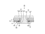
この構成によれば、パッキンは、集電体の他端側と導電性部材の胴体部との間に挟み込まれているため、集電体と導電性部材との間の隙間が生じるのを抑制することができる。
この構成によれば、パッキンは、導電性部材の内側径大部とケースの内面との間に挟み込まれる内パッキン部分に加えて、導電性部材の外側径大部とケースの外面との間に挟み込まれる外パッキン部分を有する。このため、ケースと導電性部材との隙間が生じるのを、より確実に抑制することができる。
この構成によれば、パッキンに加えて外ワッシャを設けることにより、外側径大部と内側径大部とでケース、パッキン、集電体を、より強く挟み込むことができる。
また、上記蓄電素子では、前記外パッキン部分には、前記外ワッシャの外周面に当接する突起部が設けられていてもよい。これにより、外パッキンと外ワッシャとの位置ズレを抑制することができる。
この構成によれば、パッキンは、内パッキン部分と外パッキン部分とが別体であって、且つ、材質が異なる構成である。このため、例えば内パッキン部分を、外パッキン部分よりも弾性、機密性、耐熱性、絶縁性及び耐食性の少なくとも1つが高い材質で形成するなど、とすることで、内パッキン部分と外パッキン部分とでそれぞれに適した材料で形成したものを利用することができる。
この構成によれば、集電体の他端側と、内パッキン部分とは、導電性部材の前記胴体部の軸方向に対して傾斜した面同士で接触する。このため、集電体とパッキンとが上記軸方向に平行な面同士で接触する構成に比べて、両者の接触面積を大きくすることができ、隙間が生じるのを、より確実に抑制することができる。
この構成によれば、パッキンに加えて内ワッシャを設けることにより、外側径大部と内側径大部とでケース、パッキン、集電体を、より強く挟み込むことができる。
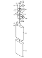
本電池の外観構成例の概要を、図1に示す。本電池は、所定の容積を有する容器1と、容器1内に収容され正極2Aおよび負極2Bを有する電極体2と、容器1の開口部1Aに配置される蓋体3と、を備える。
(1)正極用の電極端子部の構造
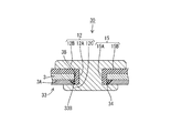
図2は、正極用の電極端子部10の構成例の斜視断面を示す。電極端子部10は、集電体13,内パッキン14、外パッキン15およびリベット12を備える。集電体13は、その図示しない一端側が、電極体2の正極2Aに接続されており、その他端側13Aが、蓋体3の内面3Aに面接触しつつ、蓋体3およびリベット12と導通している。具体的には、蓋体3の上記一端側には、例えば円形であって、直径D1の取付穴3Bが貫通形成されている。集電体13の他端側13Aには、上記取付穴3Bと同軸上に位置し、上記直径D1よりも大きい直径D2の挿入穴13Bが貫通形成されている。
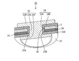
図3は、負極用の電極端子部20の構成例の斜視断面を示す。電極端子部20は、集電体23,外パッキン24,内パッキン25およびリベット22を備える。集電体23は、その図示しない一端側が、電極体2の負極2Bに接続されており、その他端側23Aが、内パッキン25によって蓋体3と絶縁され、リベット22と導通している。具体的には、蓋体3の他端側に、例えば円形の取付穴3Cが貫通形成されており、集電体23の他端側23Aには、その取付穴3Cよりも径が小さい挿入穴23Bが貫通形成されている。
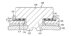
例えば、図4、図5には、比較例の電池が示されている。この比較例の電池は、容器101と、容器101の開口部に配置され、取付穴113を有する電池蓋105と、電池蓋105の取付穴113に挿入された筒状部118と、筒状部118の一方の開口端の周縁に形成された鍔部117とを有する絶縁ガスケット107と、絶縁ガスケット107の筒状部118に挿入された状態で電池蓋105にかしめ固定された軸部122と、軸部122の一端に形成され、絶縁ガスケット107の鍔部117を介して電池蓋105に配置された頭部120とを有し、正極または負極の出力端子用のリベット108と、リベット108の頭部120と絶縁ガスケット107の鍔部117との間か、電池蓋105と前記絶縁ガスケット107の鍔部117との間のうち少なくともいずれか一方に介在された絶縁パッキング110,111とを具備する電池が提案されている(例えば特許文献1参照)。ここで、102は電極体,106aは円形穴,110a,111aはリベット挿入穴,114はベントを示す。
(1)電池蓋105の凹部112内に第2の絶縁パッキング111を配置し、絶縁ガスケット107のボス部118を電池蓋105の取付穴113に挿入し、これらを嵌め合せる。
(2)絶縁ガスケット107のフランジ部117内に第1の絶縁パッキング110を挿入し、さらにリベット108の軸部121を絶縁ガスケット107の軸挿入穴119に挿入し、嵌め合せる。
(3)その後、電池蓋105から下方に貫通した軸部121に絶縁プレート106を介して孔開きのワッシャー109を挿入する。
(4)次いで、リベット108の頭部120を下方に加圧してその位置を固定しながらカシメ軸部122の下端を上方に加圧すると、リベット108の軸部121及びカシメ軸部122が自由状態よりも僅かに拡径変形(膨張変形)する。その結果、リベット108の軸部121が絶縁ガスケット107の軸挿入穴119と密着し、電池蓋105の取付穴113と絶縁ガスケット107との隙間が封止される、つまり、リベット108が電池蓋105に絶縁ガスケット107を介してかしめ固定される。
(5)ワッシャー109に負極側の導電タブ104を溶接し、正極側の導電タブ103を電池蓋105の内面に溶接する。
(6)この後に、電池蓋105を電池ケース101の開口部に嵌め合わせた後、電池蓋105と電池ケース101との嵌合面を溶接して封止する。
(7)最後に、電解液注入口115から電解液を電池ケース101内に注入したのち、電解液注入口115にプラグ116を挿入して溶接し、電解液注入口115を封止することにより電池を完成する。
(i)ケースの電位を正極あるいは負極にとるためには、ケースと電位をとるための対象物とを溶接する必要があった。このとき、溶接によって発生する粉塵やスパッタ等は、電池の構成部品を汚染し腐蝕やショート等の原因となる可能性がある。また,溶接自体の欠陥によって導通不良やスパークの発生等の可能性がある。
(ii)電極の取出し部や端子台における接合においては、容器内部を外気と遮断するシール構造が要求される一方、こうした取出し部等には複数の部品を接合しあるいは組立てを必要とすることから、シール材の歪みやズレ等によって十分にシールできないあるいは使用時の加熱−冷却のサイクルに伴うシール機能の劣化が生じることがある。
(iii)また、こうしたシール材には、弾性,機密性,耐熱性,絶縁性および耐食性が要求されるが、こうした特性を全て満たす素材は少なく、高価であり、また繰り返しの使用に耐える素材は、さらに限定される。
(a)ケースおよび集電体をリベットでカシメて挟持することによって、溶接等粉塵やスパッタ等のような電池の機能に悪影響を及ぼす可能性のある物質等の発生がなく、確実に固定された電極端子部を形成することができる。
(b)筐体として所定の強度を有し導電性を有するケースに対して集電体を重ね、同時に弾性を有する上部パッキンを挟持することによって、ケースや集電体を傷付けることなく、柔軟かつ強固に挟持し固定することができる。また、衝撃や振動等による接合部分のズレがなく確実にケースに対する導電性を有する電極端子部を形成することができる。
(c)容器としてのシール性は、弾性,耐熱性,耐蝕性および機密性のある上部パッキンを、リベットの頭部およびケースの外面に当接させることによって、確実にすることができる。特に、リベットがカシメられたときに、リベットとケースおよび集電体との隙間が生じないように、柔軟に変形しながら、より確実にこれらの当接を図ることができるとともに、絶縁性を確保することができる。
本電池においては、正極用の電極端子部は、図2に例示するような構成のみならず、用途や要求仕様に対応した種々の形態を構成することができる。以下に、その形態をいくつか例示し、本電池における電極端子部10の特徴を明確にする。
Claims (9)
- 取付穴が形成されたケースと、
前記ケース内に収容され、正極および負極を有する電極体と、
一端側が前記電極体の前記正極あるいは前記負極と接続され、他端側が前記ケースの内面と導通する集電体と、
前記ケースの前記内面のうち、前記取付穴と前記集電体の前記他端側との間の部分に接触する内パッキン部分を有するパッキンと、
前記ケースの前記取付穴に挿入された胴体部、及び、前記胴体部のうち前記ケースの内側の端部に設けられ、当該胴体部よりも径が大きい内側径大部を有し、前記内側径大部が、前記集電体の前記他端側と導通し、前記内パッキン部分に接触し、且つ、前記ケースとの間で前記内パッキン部分および前記集電体の前記他端側を挟み込んでいる導電性部材と、を備える蓄電素子。 - 前記内パッキン部分は、前記集電体の前記他端側と前記導電性部材の前記胴体部との間に挟み込まれている、請求項1に記載の蓄電素子。
- 前記導電性部材は、前記胴体部のうち前記ケースの外側の端部に設けられ、当該胴体部よりも径が大きい外側径大部を有し、
前記パッキンは、前記内パッキン部分に加えて、前記導電性部材の前記外側径大部と前記ケースの外面との間に挟み込まれる外パッキン部分を有する構成である、請求項1または2に記載の蓄電素子。 - 前記導電性部材の前記外側径大部と前記外パッキン部分と間に配置され、前記外パッキンよりも径が小さい外ワッシャを備えている、請求項3に記載の蓄電素子。
- 前記外パッキン部分には、前記外ワッシャの外周面に当接する突起部が設けられている、請求項4に記載の蓄電素子。
- 前記パッキンは、前記内パッキン部分と前記外パッキン部分とが別体であって、且つ、互いに材質が異なる構成である、請求項3から5のいずれか一項に記載の蓄電素子。
- 前記パッキンは、前記ケースの前記取付穴に接触する外周面、及び、前記導電性部材の前記胴体部に接触する内周面を有する筒状部分を有し、
前記内パッキン部分及び前記外パッキン部分の少なくとも一方のパッキン部分は前記筒状部分と別体であって、当該一方のパッキン部分には前記筒状部分の外周面の全周に亘って接触する貫通穴が形成されている、請求項3から6のいずれか一項に記載の蓄電素子。 - 前記集電体の前記他端側と、前記内パッキン部分とは、前記導電性部材の前記胴体部の軸方向に対して傾斜した面同士で接触する構成である、請求項1〜7に記載の蓄電素子。
- 前記集電体の前記他端側と前記導電性部材の前記内側径大部との間に配置されている内ワッシャを備える、請求項1〜8のいずれか一項に記載の蓄電素子。
Priority Applications (5)
| Application Number | Priority Date | Filing Date | Title |
|---|---|---|---|
| JP2012001986A JP5987320B2 (ja) | 2011-02-03 | 2012-01-10 | 蓄電素子 |
| KR1020120008209A KR101896535B1 (ko) | 2011-02-03 | 2012-01-27 | 축전 소자 |
| EP12153238.6A EP2485291B1 (en) | 2011-02-03 | 2012-01-31 | Electric storage device |
| US13/363,655 US8753766B2 (en) | 2011-02-03 | 2012-02-01 | Electric storage device |
| CN201210022937.XA CN102629672B (zh) | 2011-02-03 | 2012-02-02 | 蓄电元件 |
Applications Claiming Priority (3)
| Application Number | Priority Date | Filing Date | Title |
|---|---|---|---|
| JP2011021984 | 2011-02-03 | ||
| JP2011021984 | 2011-02-03 | ||
| JP2012001986A JP5987320B2 (ja) | 2011-02-03 | 2012-01-10 | 蓄電素子 |
Publications (2)
| Publication Number | Publication Date |
|---|---|
| JP2012178337A true JP2012178337A (ja) | 2012-09-13 |
| JP5987320B2 JP5987320B2 (ja) | 2016-09-07 |
Family
ID=45529015
Family Applications (1)
| Application Number | Title | Priority Date | Filing Date |
|---|---|---|---|
| JP2012001986A Active JP5987320B2 (ja) | 2011-02-03 | 2012-01-10 | 蓄電素子 |
Country Status (5)
| Country | Link |
|---|---|
| US (1) | US8753766B2 (ja) |
| EP (1) | EP2485291B1 (ja) |
| JP (1) | JP5987320B2 (ja) |
| KR (1) | KR101896535B1 (ja) |
| CN (1) | CN102629672B (ja) |
Cited By (5)
| Publication number | Priority date | Publication date | Assignee | Title |
|---|---|---|---|---|
| JP2015043282A (ja) * | 2013-08-26 | 2015-03-05 | 株式会社Gsユアサ | 蓄電素子 |
| JP2015204218A (ja) * | 2014-04-15 | 2015-11-16 | 株式会社豊田自動織機 | 蓄電装置 |
| WO2016060265A1 (ja) * | 2014-10-17 | 2016-04-21 | 株式会社 豊田自動織機 | 蓄電装置 |
| JP2016195036A (ja) * | 2015-03-31 | 2016-11-17 | 株式会社Gsユアサ | 蓄電素子及び蓄電素子の製造方法 |
| JPWO2015125487A1 (ja) * | 2014-02-21 | 2017-03-30 | 株式会社Gsユアサ | 蓄電素子及び蓄電素子の製造方法 |
Families Citing this family (7)
| Publication number | Priority date | Publication date | Assignee | Title |
|---|---|---|---|---|
| JP6364752B2 (ja) * | 2012-12-28 | 2018-08-01 | 株式会社Gsユアサ | 封止部材キャップ、蓄電素子、蓄電素子の製造方法 |
| US11431047B2 (en) * | 2018-05-07 | 2022-08-30 | Apple Inc. | Feedthrough with integrated insulator |
| US11145925B2 (en) | 2018-09-06 | 2021-10-12 | Apple Inc. | Cylindrical battery cell with overmolded glass feedthrough |
| US11417926B2 (en) | 2018-11-29 | 2022-08-16 | Apple Inc. | Feedthroughs for thin battery cells |
| US12191511B2 (en) | 2019-06-20 | 2025-01-07 | Apple Inc. | Battery cell with serpentine tab |
| US12183511B2 (en) | 2020-02-14 | 2024-12-31 | Ls Materials Co., Ltd. | Energy storage device |
| KR102858241B1 (ko) * | 2023-12-26 | 2025-09-09 | 삼성에스디아이 주식회사 | 이차 전지 |
Citations (5)
| Publication number | Priority date | Publication date | Assignee | Title |
|---|---|---|---|---|
| JP2005100769A (ja) * | 2003-09-24 | 2005-04-14 | Toshiba Battery Co Ltd | 角形非水電解液電池 |
| JP2006156063A (ja) * | 2004-11-29 | 2006-06-15 | Nec Tokin Corp | 二次電池 |
| JP2008251381A (ja) * | 2007-03-30 | 2008-10-16 | Kri Inc | 非水系二次電池 |
| JP2010027546A (ja) * | 2008-07-24 | 2010-02-04 | Toshiba Corp | バッテリ装置 |
| US7807285B1 (en) * | 2004-04-07 | 2010-10-05 | Quallion Llc | Battery connection structure and method |
Family Cites Families (14)
| Publication number | Priority date | Publication date | Assignee | Title |
|---|---|---|---|---|
| CN2502406Y (zh) * | 2001-09-07 | 2002-07-24 | 深圳市比亚迪锂电池有限公司 | 锂离子电池 |
| CN2502407Y (zh) | 2001-09-24 | 2002-07-24 | 姚旦 | 内置式的地球仪电池盒 |
| JP3937427B2 (ja) | 2001-11-20 | 2007-06-27 | 株式会社ジーエス・ユアサコーポレーション | 電池の製造方法 |
| US6673489B2 (en) * | 2001-12-28 | 2004-01-06 | Quallion Llc | Electric battery assembly and method of manufacture |
| JP4967216B2 (ja) * | 2003-12-05 | 2012-07-04 | 株式会社Gsユアサ | 非水電解質電池 |
| JP2004111300A (ja) | 2002-09-20 | 2004-04-08 | Japan Storage Battery Co Ltd | 非水電解質二次電池 |
| KR100865122B1 (ko) * | 2003-10-03 | 2008-10-23 | 히다치 막셀 가부시키가이샤 | 밀폐형 전지 |
| JP4780598B2 (ja) * | 2004-09-29 | 2011-09-28 | 日立マクセルエナジー株式会社 | 密閉角形電池 |
| JP5121279B2 (ja) * | 2007-03-30 | 2013-01-16 | 三洋電機株式会社 | 密閉型電池の製造方法 |
| JP2008305644A (ja) | 2007-06-06 | 2008-12-18 | Toshiba Corp | 電池 |
| JP5319947B2 (ja) * | 2008-03-25 | 2013-10-16 | 株式会社東芝 | 非水電解質電池 |
| JP5481827B2 (ja) * | 2008-10-15 | 2014-04-23 | 株式会社Gsユアサ | 電池 |
| US8236439B2 (en) * | 2009-08-14 | 2012-08-07 | Sb Limotive Co., Ltd. | Rechargeable battery |
| JP6037196B2 (ja) * | 2011-01-17 | 2016-12-07 | 株式会社Gsユアサ | 蓄電素子の製造方法 |
-
2012
- 2012-01-10 JP JP2012001986A patent/JP5987320B2/ja active Active
- 2012-01-27 KR KR1020120008209A patent/KR101896535B1/ko active Active
- 2012-01-31 EP EP12153238.6A patent/EP2485291B1/en not_active Not-in-force
- 2012-02-01 US US13/363,655 patent/US8753766B2/en active Active
- 2012-02-02 CN CN201210022937.XA patent/CN102629672B/zh not_active Expired - Fee Related
Patent Citations (5)
| Publication number | Priority date | Publication date | Assignee | Title |
|---|---|---|---|---|
| JP2005100769A (ja) * | 2003-09-24 | 2005-04-14 | Toshiba Battery Co Ltd | 角形非水電解液電池 |
| US7807285B1 (en) * | 2004-04-07 | 2010-10-05 | Quallion Llc | Battery connection structure and method |
| JP2006156063A (ja) * | 2004-11-29 | 2006-06-15 | Nec Tokin Corp | 二次電池 |
| JP2008251381A (ja) * | 2007-03-30 | 2008-10-16 | Kri Inc | 非水系二次電池 |
| JP2010027546A (ja) * | 2008-07-24 | 2010-02-04 | Toshiba Corp | バッテリ装置 |
Cited By (6)
| Publication number | Priority date | Publication date | Assignee | Title |
|---|---|---|---|---|
| JP2015043282A (ja) * | 2013-08-26 | 2015-03-05 | 株式会社Gsユアサ | 蓄電素子 |
| JPWO2015125487A1 (ja) * | 2014-02-21 | 2017-03-30 | 株式会社Gsユアサ | 蓄電素子及び蓄電素子の製造方法 |
| JP2015204218A (ja) * | 2014-04-15 | 2015-11-16 | 株式会社豊田自動織機 | 蓄電装置 |
| WO2016060265A1 (ja) * | 2014-10-17 | 2016-04-21 | 株式会社 豊田自動織機 | 蓄電装置 |
| JPWO2016060265A1 (ja) * | 2014-10-17 | 2017-06-15 | 株式会社豊田自動織機 | 蓄電装置 |
| JP2016195036A (ja) * | 2015-03-31 | 2016-11-17 | 株式会社Gsユアサ | 蓄電素子及び蓄電素子の製造方法 |
Also Published As
| Publication number | Publication date |
|---|---|
| KR20120089573A (ko) | 2012-08-13 |
| US8753766B2 (en) | 2014-06-17 |
| US20120202107A1 (en) | 2012-08-09 |
| EP2485291A1 (en) | 2012-08-08 |
| CN102629672A (zh) | 2012-08-08 |
| EP2485291B1 (en) | 2017-08-02 |
| KR101896535B1 (ko) | 2018-09-07 |
| JP5987320B2 (ja) | 2016-09-07 |
| CN102629672B (zh) | 2015-12-09 |
Similar Documents
| Publication | Publication Date | Title |
|---|---|---|
| JP5987320B2 (ja) | 蓄電素子 | |
| KR101968713B1 (ko) | 축전 소자 | |
| KR100590045B1 (ko) | 이차 전지와 이차 전지의 조립 방법 | |
| CN101315990B (zh) | 一种电池组 | |
| US9023516B2 (en) | Rechargeable battery and module thereof | |
| US8951663B2 (en) | Secondary battery | |
| CN100334748C (zh) | 二次电池 | |
| KR102246736B1 (ko) | 이차 전지 | |
| CN107026248B (zh) | 蓄电元件、蓄电装置以及蓄电元件的制造方法 | |
| CN109065822B (zh) | 纽扣电池 | |
| JP6037196B2 (ja) | 蓄電素子の製造方法 | |
| WO2014091635A1 (ja) | 積層電池および積層電池の組立方法 | |
| US20140272520A1 (en) | Battery module | |
| US20110117427A1 (en) | Batteries | |
| KR20150101383A (ko) | 축전 소자 | |
| JP6123544B2 (ja) | 蓄電素子および蓄電素子の製造方法 | |
| JP6770690B2 (ja) | 密閉型電池 | |
| JP6295695B2 (ja) | 蓄電素子及び電源モジュール | |
| JP5655715B2 (ja) | 電池 | |
| JP2004241353A (ja) | 蓄電素子の端子構造および蓄電素子 | |
| KR20180001063A (ko) | 이차 전지 | |
| US20210043896A1 (en) | Energy storage apparatus | |
| CN223066291U (zh) | 盖板组件、电芯及电池包 | |
| WO2021014705A1 (ja) | 角形二次電池 | |
| JP2020080225A (ja) | 電池 |
Legal Events
| Date | Code | Title | Description |
|---|---|---|---|
| A621 | Written request for application examination |
Free format text: JAPANESE INTERMEDIATE CODE: A621 Effective date: 20141224 |
|
| A977 | Report on retrieval |
Free format text: JAPANESE INTERMEDIATE CODE: A971007 Effective date: 20151126 |
|
| A131 | Notification of reasons for refusal |
Free format text: JAPANESE INTERMEDIATE CODE: A131 Effective date: 20151222 |
|
| A521 | Request for written amendment filed |
Free format text: JAPANESE INTERMEDIATE CODE: A523 Effective date: 20160217 |
|
| TRDD | Decision of grant or rejection written | ||
| A01 | Written decision to grant a patent or to grant a registration (utility model) |
Free format text: JAPANESE INTERMEDIATE CODE: A01 Effective date: 20160712 |
|
| A61 | First payment of annual fees (during grant procedure) |
Free format text: JAPANESE INTERMEDIATE CODE: A61 Effective date: 20160725 |
|
| R150 | Certificate of patent or registration of utility model |
Ref document number: 5987320 Country of ref document: JP Free format text: JAPANESE INTERMEDIATE CODE: R150 |