JP2012166327A - Polishing apparatus - Google Patents
Polishing apparatus Download PDFInfo
- Publication number
- JP2012166327A JP2012166327A JP2011031308A JP2011031308A JP2012166327A JP 2012166327 A JP2012166327 A JP 2012166327A JP 2011031308 A JP2011031308 A JP 2011031308A JP 2011031308 A JP2011031308 A JP 2011031308A JP 2012166327 A JP2012166327 A JP 2012166327A
- Authority
- JP
- Japan
- Prior art keywords
- polishing
- support
- polishing apparatus
- reciprocating linear
- linear motion
- Prior art date
- Legal status (The legal status is an assumption and is not a legal conclusion. Google has not performed a legal analysis and makes no representation as to the accuracy of the status listed.)
- Granted
Links
Images
Classifications
-
- B—PERFORMING OPERATIONS; TRANSPORTING
- B24—GRINDING; POLISHING
- B24B—MACHINES, DEVICES, OR PROCESSES FOR GRINDING OR POLISHING; DRESSING OR CONDITIONING OF ABRADING SURFACES; FEEDING OF GRINDING, POLISHING, OR LAPPING AGENTS
- B24B19/00—Single-purpose machines or devices for particular grinding operations not covered by any other main group
- B24B19/22—Single-purpose machines or devices for particular grinding operations not covered by any other main group characterised by a special design with respect to properties of the material of non-metallic articles to be ground
- B24B19/226—Single-purpose machines or devices for particular grinding operations not covered by any other main group characterised by a special design with respect to properties of the material of non-metallic articles to be ground of the ends of optical fibres
Landscapes
- Engineering & Computer Science (AREA)
- Mechanical Engineering (AREA)
- Grinding And Polishing Of Tertiary Curved Surfaces And Surfaces With Complex Shapes (AREA)
- Constituent Portions Of Griding Lathes, Driving, Sensing And Control (AREA)
- Finish Polishing, Edge Sharpening, And Grinding By Specific Grinding Devices (AREA)
Abstract
【課題】研磨精度を維持するために定期的に交換が必要な消耗部品点数を削減できる研磨装置を提供する。
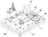
【解決手段】ワークの端面を研磨する研磨面20aを表面に有する研磨盤20と、研磨盤20の裏面20bを所定平面に沿って移動自在に支持する支持機構30と、研磨盤20の研磨面にワークの端面が当接するようにワークを保持するワークホルダ50と、研磨盤20に円運動をさせつつ往復直線運動をさせる駆動機構70とを有する。
【選択図】図1A polishing apparatus capable of reducing the number of consumable parts that need to be periodically replaced in order to maintain polishing accuracy.
A polishing disk 20 having a polishing surface 20a for polishing an end face of a work, a support mechanism 30 for supporting a back surface 20b of the polishing disk 20 movably along a predetermined plane, and a polishing surface of the polishing disk 20. A work holder 50 that holds the work so that the end face of the work comes into contact with the work, and a drive mechanism 70 that makes the polishing board 20 perform a reciprocating linear motion while making a circular motion.
[Selection] Figure 1
Description
本発明は、研磨装置に関し、具体的には、光ファイバーの接続端面の研磨に好適な研磨装置に関する。 The present invention relates to a polishing apparatus, and more specifically, to a polishing apparatus suitable for polishing a connection end face of an optical fiber.
複数本の光ファイバーを相互に突き合わせて接続し、あるいは、各種光デバイスに対して光ファイバーを接続するために用いられる光コネクタは、通常、光ファイバーが挿通する光ファイバープラグを有する。従来の光ファイバープラグは、ジルコニアセラミックスなどの耐摩耗性に優れた低膨張率の材料を円柱状に加工したものである。この光ファイバープラグの接続端面の中央部には光ファイバーの先端面が露出した状態となっている。接続端面は、20mm程度の曲率半径の凸球面に形成される。 An optical connector used for connecting a plurality of optical fibers to each other or connecting optical fibers to various optical devices usually has an optical fiber plug through which the optical fiber is inserted. A conventional optical fiber plug is obtained by processing a low expansion coefficient material having excellent wear resistance such as zirconia ceramics into a cylindrical shape. The front end surface of the optical fiber is exposed at the center of the connection end surface of the optical fiber plug. The connection end surface is formed as a convex spherical surface having a radius of curvature of about 20 mm.
このような光ファイバープラグの接続端面を所定曲率の凸球面に加工するための研磨装置が特許文献1に開示されている。特許文献1に開示された研磨装置は、弾性シートを介して研磨フィルムが表面に貼付され、所定平面内で円運動が可能に支持された研磨盤と、光ファイバープラグが装着されるプラグホルダーが設けられたスライダとを有する。そして、この研磨装置は、光ファイバープラグの接続端面を研磨盤に押し付けた状態で、研磨盤を円運動させつつ、スライダを研磨盤に対して往復移動させることにより、光ファイバープラグの接続端面を研磨する。
A polishing apparatus for processing the connection end surface of such an optical fiber plug into a convex spherical surface having a predetermined curvature is disclosed in
ところで、上記したような研磨装置においては、研磨盤を円運動可能に支持する支持機構やスライダをガイドするガイドレールが使用とともに摩耗すると、研磨面およびスライダの平行度、寸法が変動し、光ファイバープラグの接続端面の必要な研磨加工精度が得られなくなる可能性がある。また、研磨盤を円運動させる機構の構成部品に摩耗が生じると、当該機構に遊びが発生し、研磨フィルムの研磨性能を十分に発揮させることができず、光ファイバーコネクタの接続端面の外観特性および光学特性を劣化させる可能性がある。光ファイバープラグの接続端面の研磨精度を維持するためには、多数の部品を頻繁に交換する必要があり、部品コストが高くなるとともに、交換作業に多くの工数が必要となる。 By the way, in the polishing apparatus as described above, when the support mechanism for supporting the polishing disk and the guide rail for guiding the slider wear with use, the parallelism and dimensions of the polishing surface and the slider change, and the optical fiber plug is changed. There is a possibility that the required polishing accuracy of the connection end surface of the contact may not be obtained. In addition, when wear occurs in the components of the mechanism that causes the polishing disk to move circularly, play occurs in the mechanism, and the polishing performance of the polishing film cannot be fully exhibited, and the appearance characteristics of the connection end face of the optical fiber connector and There is a possibility of deteriorating optical properties. In order to maintain the polishing accuracy of the connection end face of the optical fiber plug, it is necessary to frequently replace a large number of parts, which increases the cost of the parts and requires a large number of man-hours for the replacement work.
本発明の目的の一つは、研磨精度を維持するために定期的に交換が必要な消耗部品点数を削減できる研磨装置を提供することにある。 One object of the present invention is to provide a polishing apparatus that can reduce the number of consumable parts that need to be replaced periodically in order to maintain the polishing accuracy.
本発明に係る研磨装置は、ワークの端面を研磨する研磨面を表面に有する研磨盤と、前記研磨盤の裏面を所定平面に沿って移動自在に支持する支持機構と、前記研磨盤の研磨面にワークの端面が当接するようにワークを保持するワークホルダと、前記研磨盤を円運動させつつ往復直線運動させる駆動機構と、を有することを特徴とする。 A polishing apparatus according to the present invention includes a polishing disk having a polishing surface for polishing an end face of a workpiece, a support mechanism that supports a back surface of the polishing disk movably along a predetermined plane, and a polishing surface of the polishing disk It has a work holder which holds a work so that the end face of a work contacts, and a drive mechanism which makes a reciprocating linear motion of the above-mentioned grinding disk while making a circular motion.
本発明によれば、研磨盤を円運動および往復直線運動させることにより、ワークホルダを移動させる必要がなく、研磨精度を担う機構を支持機構に集約させることができる。この結果、ワークの研磨精度を維持するために定期的に交換が必要な消耗部品を削減できる。また、ワークホルダは固定であり、それに取り付けられているワークが往復直線運動をしないので、研磨時のワークの保持も簡略化できる。 According to the present invention, it is not necessary to move the work holder by moving the polishing disc in a circular motion and a reciprocating linear motion, and the mechanism responsible for the polishing accuracy can be integrated into the support mechanism. As a result, it is possible to reduce consumable parts that need to be replaced regularly in order to maintain the workpiece polishing accuracy. Further, since the work holder is fixed and the work attached to the work holder does not reciprocate linearly, holding of the work during polishing can be simplified.
以下、本発明の実施形態について添付図面を参照して説明する。 Embodiments of the present invention will be described below with reference to the accompanying drawings.
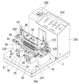
本発明の一実施形態に係る研磨装置の外観を図1に示す。本実施形態に係る研磨装置は、図10に示すような、光コネクタ300に収納された光ファイバーフェルール301の接続端面301aの研磨に用いられる。この研磨装置は、ベース10、光ファイバーフェルール301の接続端面301aを研磨する研磨面を有する研磨盤20、研磨盤20を支持する支持機構30、研磨盤20を円運動および往復直線運動させる駆動機構70、および、複数の光コネクタ300を保持するワークホルダ50を有する。なお、ここで、円運動とは、研磨盤20の全ての点の移動軌跡が所定半径の円を描くように、研磨盤20を運動させることをいう。
An appearance of a polishing apparatus according to an embodiment of the present invention is shown in FIG. The polishing apparatus according to this embodiment is used for polishing the
ベース10は、防振ゴムなどを組み込んだペデスタル1を介して作業床面上に載置されている。ベース10は、例えば長辺および短辺が300mm×250mmの平坦な取り付け面(基準面)10aを有する板状部材である。ベース10には、耐摩耗性および耐蝕性に優れ、かつ鋳鋼やアルミニウム合金などの一般的な金属よりも熱変形の少ない石定盤を採用できる。また、ベース10の取り付け面10aの平面度は、同時に研磨される光コネクタ300の数およびその配列間隔の長さによるが、一般的にはJIS2級以上の精度であればよい。ベース11を構成する材料の線膨張係数が1.1×10⁻⁵/℃以下であれば、鋳鉄やSUS430,50%ニッケル鋼,普通鋼などの金属をベース11として採用することも可能である。なお、ペデスタル1には、ベース10に隣接して後述するモータやモータの動力伝達系を覆うカバー200が設けられ、このカバー200の上部に、各種ボタン、表示灯等からなる操作部210および緊急停止スイッチ220が設けられている
The
ワークホルダ50は、複数の光コネクタ装着孔51が形成された取り付け板52、取り付け板52の両端部に設けられた案内支柱58、案内支柱58により上下方向にガイドされる昇降ブロック56、および、昇降ブロック56に固定された複数の押え部材54を有する。
The
取り付け板52は、長手方向の両端部がベース1に互いに離隔して設置された2つの支持台110の上面に載置され、当該両端部の上面を2つの支持台110上にそれぞれ設けられたトグルクランプ120によりクランプすることにより、支持台110に固定される。なお、トグルクランプ120は、レバー121を操作することにより、取り付け板52をクランプ/アンクランプするように構成されている。複数の光コネクタ装着孔51は、取り付け板52の長手方向に沿って所定間隔で前後2列(12個ずつ)に配列されている。図示しない後方の列の光コネクタ装着孔51は、前方の列の光コネクタ装着孔51に対して、配列ピッチの半分だけずらして配列されている。複数の押さえ部材54は、複数の光コネクタ装着孔51にそれぞれ対応して設けられている。
The
昇降ブロック56は、案内支柱58により上下方向に移動可能になっているとともに、光コネクタ300を押さえ部材54が押圧する所定位置で図示しないクランプ機構によりクランプされる。昇降ブロック56を上昇させて、複数の光コネクタ装着孔51にそれぞれ光コネクタ300を装着し、その後、昇降ブロック56を下降させてクランプすると、光コネクタ300は押さえ部材54により下方に向けて押圧されつつワークホルダ50に装着される。これにより、光ファイバーフェルール301の接続端面301aは、研磨盤20の研磨面に押し当てられる。
The
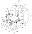
ワークホルダ50を取り外した状態の研磨装置を図2に示す。研磨盤20は、図2に示すように、略正方形状の外形を有する板状部材である。研磨盤20の表面20aおよび裏面20bは、平坦面で構成され、表面20aには、弾性変形可能な弾性シートを介して研磨フィルムが貼着され、この研磨フィルムが研磨面を構成する。研磨盤20は、耐摩耗性に優れた硬質材料で形成され、特に、後述するように、支持機構30の剛球45により支持される裏面20bは、剛球45よりも硬度が高くなるように形成される。
FIG. 2 shows the polishing apparatus with the
図2の研磨装置から、研磨盤20をさらに取り外した状態を図3に示す。
支持機構30は、上記した2つの支持台110の間に配置され、かつ、ベース10の取り付け面10aに並列して設置された2つの支持部材31と、複数の剛球45と、剛球45をガイドする各支持部材31の上面にそれぞれ設置された2つのガイド部材40と、を有する。
FIG. 3 shows a state where the
The
支持部材31は、ベース10の両側面に平行になるように設置され、その上面は、研磨盤20を支持する平坦な支持面31aとなっている。支持面31aは、ベース10の取り付け面10aは平行な平面である。支持部材31は、研磨盤20と同様に、耐摩耗性に優れた硬質材料で形成され、特に、後述するように、剛球45を支持する支持面31aは剛球45よりも硬度が高くなるように形成される。
The
複数の剛球45は、支持部材31の支持面31aと研磨盤20の裏面20bとの間に介在し、後述する研磨盤20の支持面31aに対する円運動および往復直線運動を受容する複数のベアリング要素として機能する。
The plurality of
ここで、ガイド部材40の構造を図7および図8に示す。ガイド部材40は、長細い平板状部材であり、各剛球45を案内する複数のガイド孔41、および、平板部分の短手方向の両端部に形成された下方に向けて突出する突出部43を有する。ガイド部材40の平板部分の厚さは、図8(B)に示すように、剛球45の直径よりも若干短い。これにより、研磨盤20の裏面20bは、複数の剛球45と接触し、ガイド部材40とは接触せず、また、研磨盤20は、複数の剛球45に接する所定平面に沿って移動自在に支持される。ガイド孔41は、ガイド部材40の長手方向に直交する方向(短手方向)に延びる長孔からなり、ガイド部材40の長手方向に沿って配列されている。それぞれ複数(4つ)のガイド孔41からなる4つのガイド孔列が、長手方向および短手方向においてそれぞれ対称な位置に形成されている。このガイド孔41は、後述する研磨盤20の円運動および往復直線運動により、支持部材31の支持面31aと研磨盤20の裏面20bに対して転動又は摺動する剛球45の可動範囲を規定している。剛球45の可動範囲を規定することにより、剛球45は、支持部材31の支持面31aから落下しない。また、ガイド孔41の底部は、その上部よりも若干幅が狭く形成され、剛球45がガイド孔41の底部を通じて落下しないようになっている。両側の突出部43は、支持部材31の両側面とそれぞれ対向することにより、ガイド部材40を支持部材31の長手方向に案内する。なお、ガイド部材40は支持部材31の長手方向に移動自在に支持されているが、支持部材31から脱落しないように、支持部材31の長手方向の所定範囲でのみ可動となっている。
Here, the structure of the
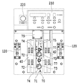
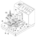
図3の研磨装置における駆動機構70のカバーを取り外した状態を図4および図5に示す。また、図5においてカバー200および駆動機構70の一部を取り外した状態を図6に示す。駆動機構70は、ベース10に設置された直動ガイド80により、支持部材31の長手方向、すなわち、往復直線運動方向に移動自在に案内されたスライダ71と、このスライダ71に互いに離隔して配置されかつ回転自在に支持された複数(2つ)の回転部材72とを有する。駆動機構70は、回転部材72を回転運動させるとともにスライダ71を往復直線運動させることにより、研磨盤20に円運動および往復直線運動させる。
4 and 5 show a state where the cover of the
2つの回転部材72は、その回転中心から所定距離だけ偏心し、研磨盤20の裏面20bに形成されたピン孔21(図9参照)に挿入される偏心ピン73をそれぞれ有する。各回転部材72は、プーリ77と同心に連結されている。各プーリ77は、無端の歯付きベルト75と噛み合っており、歯付きベルト75は、モータ79の出力軸に噛み合っている。また、歯付きベルト75は、スライダ71に設けられたテンショナ77によりテンションが調整されている。2つの回転部材72は、共通の歯付きベルト75によりモータ79の回転が伝達され、互いに同期して回転する。
The two
スライダ71は、その一側部に無端のベルト82の一部が固定部材83により固定されている。ベルト82は、ベース19に回転自在に設けられたプーリ84に巻回されているとともに、ペデスタル1に回転自在に設けられたプーリ86に巻回されている。プーリ86は、直径が異なるプーリ88と同心に連結され、このプーリ88とモータ92の出力軸とにベルト90が巻回されている。これにより、モータ92の回転がベルト90を介してベルト82の直線運動に変換されてスライダ71に伝達される。モータ92の出力軸を往復回転させることにより、スライダ71を往復直線運動させることができる。
A part of the
駆動動機構70による研磨盤20の円運動および往復直線運動について図9を参して説明する。モータ79を所定方向に回転させると、2つの回転部材20が中心軸線Oを中心にR1方向に同期して回転し、研磨盤20は、中心軸線Oと偏心ピン73との距離により規定される半径R1の円運動をする。このとき、2つの偏心ピン73が研磨盤20の2つのピン孔21にそれぞれ係合しているので、研磨盤20が回転することはない。また、モータ92を一方向に一定量回転させ、逆方向に一定量回転させる動作を繰り返すと、スライダ71は、L1およびL2方向に同じ距離だけ交互に移動する。これにより、研磨盤20は、往復直線運動する。
The circular motion and the reciprocating linear motion of the polishing
ここで、24本の光コネクタ300の接続端面301aを研磨した場合の、研磨盤20に対する接続端面301aの移動軌跡を図11に模式的に示す。研磨盤20を円運動させながら往復直線運動させることにより、接続端面301aの移動軌跡を完全に重なり合わないようにすることができる。
Here, when the
本実施形態に係る研磨装置においては、転動や摺動により摩耗を生じる部品のうち、光コネクタ300の接続端面301aの研磨精度に影響を与え、定期的に交換する必要がある消耗部品は、複数の剛球45のみである。すなわち、接続端面301aの研磨精度を管理するための消耗部品は、複数の剛球45に集約されている。したがって、比較的短い周期で交換すべき消耗部品は、剛球45のみであり、剛球45の精度を管理すれば、接続端面301aの研磨精度を常に高く維持することができる。例えば、駆動機構70の偏心ピン73や直動ガイド80は摩耗するが、これらが摩耗したとしても、接続端面301aの研磨精度に影響を与えることがない。このため、剛球45以外の消耗部品については、交換周期を大幅に延ばすことができる。
In the polishing apparatus according to the present embodiment, among the parts that wear due to rolling and sliding, consumable parts that affect the polishing accuracy of the
また、本実施形態の研磨装置は、研磨中に光コネクタ300の接続端面301aと研磨盤20との間に作用する力が、剛球45に集中し、駆動機構70にほとんど及ばない構造を有するため、駆動機構70における摩耗を生じる部品の寿命をさらに延ばすことができる。
Further, the polishing apparatus according to the present embodiment has a structure in which the force acting between the
また、本実施形態の研磨装置は、ガイド部材40を支持部材31に移動可能に設けることにより、ガイド部材40が剛球45の転動を妨げるのをできるだけ抑制している。すなわち、ガイド部材40のガイド孔41の形成方向以外に剛球45を移動させる力が剛球45に作用した場合に、ガイド部材40を往復直線運動方向に移動可能にすることにより、ガイド部材40が剛球45の転動を妨げるのを極力抑制している。これにより、剛球45の摩耗の進行を遅らせることができる。
Further, the polishing apparatus of the present embodiment suppresses the
さらに、本実施形態の研磨装置は、ワークホルダは固定であり、それに取り付けられているワークが往復直線運動をしない。このため、研磨時に光コネクタに接続された光ケーブルが座屈せず光ケーブルに負荷がかかることがないので、研磨時のワーク(光コネクタ)の保持も簡略化できる。 Furthermore, in the polishing apparatus of this embodiment, the work holder is fixed, and the work attached thereto does not reciprocate linearly. For this reason, since the optical cable connected to the optical connector at the time of polishing does not buckle and a load is not applied to the optical cable, it is possible to simplify the holding of the workpiece (optical connector) at the time of polishing.
上記実施形態では、ガイド部材40のガイド孔41の形成方向を往復直線運動方向に直交する方向としたが、これに限定されない。例えば、図12に示すように、往復直線運動方向に対して互いに逆向きに傾斜したガイド孔41A_1および41A_2を有するガイド部材40A、あるいは、図13に示すように、往復直線運動方向に対して全て同じ向きに傾斜したガイド孔41Bを有するガイド部材40Bを採用することができる。また、上記実施形態では、一のベアリング要素として、単一の剛球を例に挙げたが、本発明はこれに限定されない。例えば、図14に示すように、環状のリテーナ47に保持された複数の剛球48を一のベアリング要素としてもよい。この場合に、リテーナ47が往復直線運動方向に直交する方向に形成されたガイド孔41Cによって移動可能にガイドされる。
In the above-described embodiment, the formation direction of the
上記実施形態では、ベアリング要素として、転動する剛球を例に挙げたが、本発明はこれに限定されない。例えば、研磨盤と支持面との間の摩擦係数が低い摺動部材を剛球の代わりにベアリング要素として採用することも可能である。 In the said embodiment, although the hard sphere to roll was mentioned as an example as a bearing element, this invention is not limited to this. For example, a sliding member having a low friction coefficient between the polishing disk and the support surface can be used as a bearing element instead of a hard sphere.
1…ペデスタル
10…ベース
20…研磨盤
21…ピン孔
30…支持機構
31…支持部材
31a…支持面
40…ガイド部材
41…ガイド孔
45…剛球
50…ワークホルダ
70…駆動機構
71…スライダ
72…回転部材
73…偏心ピン
80…直動ガイド
DESCRIPTION OF
Claims (10)
前記研磨盤の裏面を所定平面に沿って移動自在に支持する支持機構と、
前記研磨盤の研磨面にワークの端面が当接するようにワークを保持するワークホルダと、
前記研磨盤を円運動させつつ往復直線運動させる駆動機構と、
を有することを特徴とする研磨装置。 A polishing machine having a polishing surface for polishing the end face of the workpiece,
A support mechanism for movably supporting the back surface of the polishing board along a predetermined plane;
A work holder for holding the work so that the end face of the work comes into contact with the polishing surface of the polishing machine;
A drive mechanism for reciprocating linear movement while circularly moving the polishing disc;
A polishing apparatus comprising:
前記複数のガイド孔の各々は、前記往復直線運動の方向とは異なる方向に延在していることを特徴とする請求項3に記載の研磨装置。 The guide member has a plurality of guide holes defining a movable range of each of the plurality of bearing elements,
The polishing apparatus according to claim 3, wherein each of the plurality of guide holes extends in a direction different from the direction of the reciprocating linear motion.
前記複数のベアリング要素およびガイド部材は、前記複数の支持部材の支持面の各々に設けられていることを特徴とする請求項3に記載の研磨装置。 The support member includes a plurality of support members arranged in parallel and extending in the direction of the reciprocating linear motion,
The polishing apparatus according to claim 3, wherein the plurality of bearing elements and the guide member are provided on each of support surfaces of the plurality of support members.
前記スライダに回転自在に支持され、かつ、その回転中心から所定距離だけ偏心した位置で前記研磨盤に係合する回転部材と、を有することを特徴とする請求項1に記載の研磨装置。 The drive mechanism is a slider guided to be movable in the direction of the reciprocating linear motion;
The polishing apparatus according to claim 1, further comprising: a rotating member that is rotatably supported by the slider and that engages the polishing disk at a position that is eccentric from the center of rotation by a predetermined distance.
前記駆動機構は、前記第1および第2の回転部材を互いに同期して回転させるための歯付きベルトと、当該歯付きベルトのテンションを調整するテンショナとを含むことを特徴とする請求項7に記載の研磨装置。 The rotating member includes first and second rotating members that are spaced apart from each other,
The drive mechanism includes a toothed belt for rotating the first and second rotating members in synchronization with each other, and a tensioner for adjusting a tension of the toothed belt. The polishing apparatus as described.
前記支持機構およびワークホルダは、前記ベースの基準面に共通に設けられていることを特徴とする請求項1に記載の研磨装置。 A base having a reference surface;
The polishing apparatus according to claim 1, wherein the support mechanism and the work holder are provided in common on a reference surface of the base.
Priority Applications (4)
| Application Number | Priority Date | Filing Date | Title |
|---|---|---|---|
| JP2011031308A JP5714932B2 (en) | 2011-02-16 | 2011-02-16 | Polishing equipment |
| PCT/JP2012/000891 WO2012111290A1 (en) | 2011-02-16 | 2012-02-09 | Polishing apparatus |
| CN201280009339.7A CN103391831B (en) | 2011-02-16 | 2012-02-09 | Lapping device |
| US13/985,199 US9211627B2 (en) | 2011-02-16 | 2012-02-09 | Polishing apparatus |
Applications Claiming Priority (1)
| Application Number | Priority Date | Filing Date | Title |
|---|---|---|---|
| JP2011031308A JP5714932B2 (en) | 2011-02-16 | 2011-02-16 | Polishing equipment |
Publications (2)
| Publication Number | Publication Date |
|---|---|
| JP2012166327A true JP2012166327A (en) | 2012-09-06 |
| JP5714932B2 JP5714932B2 (en) | 2015-05-07 |
Family
ID=46672237
Family Applications (1)
| Application Number | Title | Priority Date | Filing Date |
|---|---|---|---|
| JP2011031308A Active JP5714932B2 (en) | 2011-02-16 | 2011-02-16 | Polishing equipment |
Country Status (4)
| Country | Link |
|---|---|
| US (1) | US9211627B2 (en) |
| JP (1) | JP5714932B2 (en) |
| CN (1) | CN103391831B (en) |
| WO (1) | WO2012111290A1 (en) |
Cited By (1)
| Publication number | Priority date | Publication date | Assignee | Title |
|---|---|---|---|---|
| JPWO2017085884A1 (en) * | 2015-11-20 | 2018-09-06 | エヌ・ティ・ティ・アドバンステクノロジ株式会社 | Multi-stage batch polishing method and polishing film for optical fiber connector end face |
Families Citing this family (12)
| Publication number | Priority date | Publication date | Assignee | Title |
|---|---|---|---|---|
| CN105437041A (en) * | 2014-08-18 | 2016-03-30 | 泰科电子(上海)有限公司 | Polishing device |
| CN104907926B (en) * | 2015-06-16 | 2017-08-18 | 江苏天罡精密铸造有限公司 | A kind of feeding device of race ring ditch superfinishing machine |
| CN106064341A (en) * | 2016-07-25 | 2016-11-02 | 印杰 | A kind of glass plate through hole polishing machine |
| CN109129029B (en) * | 2017-06-27 | 2022-04-08 | 康普技术有限责任公司 | Polishing machines and related polishing methods |
| JP6964754B2 (en) * | 2018-03-06 | 2021-11-10 | エヌ・ティ・ティ・アドバンステクノロジ株式会社 | Optical connector polishing jig |
| US11565368B2 (en) * | 2019-08-14 | 2023-01-31 | Toyota Motor Engineering & Manufacturing North America, Inc. | Sanding apparatus with multiple part engagement members |
| CN111421297B (en) * | 2020-04-16 | 2022-05-27 | 昆明电机厂有限责任公司 | Method for on-site treatment of damaged thrust bearing surface |
| CN111745504B (en) * | 2020-05-20 | 2022-06-21 | 深圳市裕展精密科技有限公司 | Polishing mechanism, polishing device and polishing method |
| CN113601382A (en) * | 2021-07-29 | 2021-11-05 | 合肥华峰暖通设备有限公司 | Burnishing device is used in spiral steel pipe processing |
| US12271039B2 (en) | 2021-12-17 | 2025-04-08 | Domaille Engineering, Llc | Optical fiber polisher with controlled platen stopping position |
| CN116587126B (en) * | 2023-05-04 | 2026-01-06 | 上饶市富泉有机硅制品有限公司 | A silicone mold polishing and grinding device |
| CN118046150B (en) * | 2024-04-11 | 2024-06-21 | 潍坊鸿洋机械科技有限公司 | Automobile exhaust pipe manufacturing, processing and welding device |
Citations (10)
| Publication number | Priority date | Publication date | Assignee | Title |
|---|---|---|---|---|
| JPS61284380A (en) * | 1985-06-07 | 1986-12-15 | 株式会社日立製作所 | Gearing for robot |
| JPS62255056A (en) * | 1986-04-25 | 1987-11-06 | Kyushu Denshi Kinzoku Kk | Double face grinder |
| JPH04244646A (en) * | 1990-09-26 | 1992-09-01 | Gates Power Drive Prod Inc | Belt tensioner, belt driving system and belt tensioning method |
| JPH08257854A (en) * | 1995-03-24 | 1996-10-08 | Ntn Corp | Moving table and its holder |
| JPH10235542A (en) * | 1997-02-27 | 1998-09-08 | Seiko Instr Inc | End face grinding method and device therefor |
| JP2000084822A (en) * | 1998-09-14 | 2000-03-28 | Seiko Giken:Kk | End surface polishing device for optical fiber |
| JP2001259986A (en) * | 2000-03-13 | 2001-09-25 | Seiko Instruments Inc | End face polishing device |
| US20010024931A1 (en) * | 1998-06-29 | 2001-09-27 | Mike Buzzetti | Method and apparatus for polishing |
| JP2003011047A (en) * | 2001-06-29 | 2003-01-15 | Ntt Advanced Technology Corp | Ferrule end face polishing method and apparatus |
| JP2003205446A (en) * | 2002-01-09 | 2003-07-22 | Ntt Advanced Technology Corp | Polishing method and apparatus |
Family Cites Families (17)
| Publication number | Priority date | Publication date | Assignee | Title |
|---|---|---|---|---|
| JPS6412164A (en) * | 1987-06-30 | 1989-01-17 | Mitsuboshi Belting Ltd | Multi-shaft transmission mechanism with cogged belt |
| JPH0767663B2 (en) * | 1989-06-23 | 1995-07-26 | 株式会社精工技研 | Optical fiber end face polishing machine |
| US5218786A (en) * | 1991-10-04 | 1993-06-15 | Seikoh Giken Co., Ltd. | Apparatus for grinding ferrules for ribbon type optical fibers |
| US5349784A (en) * | 1992-07-10 | 1994-09-27 | Molex Incorporated | Optical fiber polishing apparatus |
| US5947797A (en) * | 1996-09-11 | 1999-09-07 | Buzzetti; Mike | Computer-controlled method for polishing |
| US5823859A (en) * | 1996-12-18 | 1998-10-20 | Erdogan; Cuneyt | Method of contouring optical fiber end faces and apparatus used therefor |
| US5813081A (en) * | 1997-04-04 | 1998-09-29 | Alcoa Fujikura Limited | Circular device for cleaning the ends of optical fibers |
| EP1048963A1 (en) * | 1999-04-30 | 2000-11-02 | Ntt Advanced Technology Corporation | Cleaning tool for optical fiber connectors |
| US6415471B1 (en) * | 1999-06-30 | 2002-07-09 | Corning Cable Systems Llc | Device for cleaning mechanism for fiber optic connectors |
| JP2002210644A (en) * | 2001-01-18 | 2002-07-30 | Seiko Instruments Inc | End surface polishing device |
| TW485863U (en) * | 2001-08-13 | 2002-05-01 | Hermosa Thin Film Co Ltd | Polishing equipment for end face of optical fiber |
| JP5031957B2 (en) * | 2001-08-30 | 2012-09-26 | Thk株式会社 | Linear actuator |
| US6918816B2 (en) * | 2003-01-31 | 2005-07-19 | Adc Telecommunications, Inc. | Apparatus and method for polishing a fiber optic connector |
| KR100513139B1 (en) * | 2004-02-26 | 2005-09-07 | 조형준 | Driving apparatus for polishing disk |
| CN100361782C (en) * | 2004-11-10 | 2008-01-16 | 中南大学 | Ultrasonic mechanical compound grinding and polishing method and device for end face of optical fiber connector |
| TWI289496B (en) * | 2006-06-29 | 2007-11-11 | Kow-Je Ling | Grinding tool for the end of workpiece |
| TW201111095A (en) * | 2009-09-23 | 2011-04-01 | Univ Nat Formosa | Round trajectory generation device |
-
2011
- 2011-02-16 JP JP2011031308A patent/JP5714932B2/en active Active
-
2012
- 2012-02-09 US US13/985,199 patent/US9211627B2/en active Active
- 2012-02-09 CN CN201280009339.7A patent/CN103391831B/en active Active
- 2012-02-09 WO PCT/JP2012/000891 patent/WO2012111290A1/en not_active Ceased
Patent Citations (10)
| Publication number | Priority date | Publication date | Assignee | Title |
|---|---|---|---|---|
| JPS61284380A (en) * | 1985-06-07 | 1986-12-15 | 株式会社日立製作所 | Gearing for robot |
| JPS62255056A (en) * | 1986-04-25 | 1987-11-06 | Kyushu Denshi Kinzoku Kk | Double face grinder |
| JPH04244646A (en) * | 1990-09-26 | 1992-09-01 | Gates Power Drive Prod Inc | Belt tensioner, belt driving system and belt tensioning method |
| JPH08257854A (en) * | 1995-03-24 | 1996-10-08 | Ntn Corp | Moving table and its holder |
| JPH10235542A (en) * | 1997-02-27 | 1998-09-08 | Seiko Instr Inc | End face grinding method and device therefor |
| US20010024931A1 (en) * | 1998-06-29 | 2001-09-27 | Mike Buzzetti | Method and apparatus for polishing |
| JP2000084822A (en) * | 1998-09-14 | 2000-03-28 | Seiko Giken:Kk | End surface polishing device for optical fiber |
| JP2001259986A (en) * | 2000-03-13 | 2001-09-25 | Seiko Instruments Inc | End face polishing device |
| JP2003011047A (en) * | 2001-06-29 | 2003-01-15 | Ntt Advanced Technology Corp | Ferrule end face polishing method and apparatus |
| JP2003205446A (en) * | 2002-01-09 | 2003-07-22 | Ntt Advanced Technology Corp | Polishing method and apparatus |
Cited By (1)
| Publication number | Priority date | Publication date | Assignee | Title |
|---|---|---|---|---|
| JPWO2017085884A1 (en) * | 2015-11-20 | 2018-09-06 | エヌ・ティ・ティ・アドバンステクノロジ株式会社 | Multi-stage batch polishing method and polishing film for optical fiber connector end face |
Also Published As
| Publication number | Publication date |
|---|---|
| JP5714932B2 (en) | 2015-05-07 |
| US9211627B2 (en) | 2015-12-15 |
| CN103391831A (en) | 2013-11-13 |
| CN103391831B (en) | 2016-06-22 |
| US20130331008A1 (en) | 2013-12-12 |
| WO2012111290A1 (en) | 2012-08-23 |
Similar Documents
| Publication | Publication Date | Title |
|---|---|---|
| JP5714932B2 (en) | Polishing equipment | |
| US4262974A (en) | Linear bearing apparatus | |
| EP0500106A1 (en) | Moving stage | |
| CN112969017A (en) | Camera module and electronic equipment | |
| JP6349029B2 (en) | Polishing equipment | |
| EP2674995A1 (en) | Moving mechanism, electronic component transport device, electronic component inspection device | |
| JP5677279B2 (en) | Brake drum polishing equipment | |
| WO2011092744A1 (en) | Optical fiber polishing apparatus | |
| JP2017067077A (en) | Linear motion guide bearing device | |
| JP4704047B2 (en) | Die cushion device | |
| JP3673703B2 (en) | Polishing tool | |
| JP2009039853A5 (en) | ||
| JP7309403B2 (en) | rotating stage | |
| CN209737339U (en) | be used for automatic burnishing and polishing tool of plastic goods | |
| KR101441276B1 (en) | Apparatus for Grinding Saw Blade | |
| WO2011092745A1 (en) | Constant velocity reciprocating linear movement device and optical fiber polishing apparatus | |
| CN115741316A (en) | Constant-distance grinding device | |
| KR20120052862A (en) | Base unit of semiconductor test device | |
| JP5948077B2 (en) | Plunger unit, positioning device | |
| US7594418B2 (en) | Arc type blade transfer apparatus | |
| CN215268677U (en) | Clamp apparatus | |
| JP2003005086A (en) | Microscopic apparatus | |
| JP2015038472A (en) | Stage device | |
| JP2012041972A (en) | Linear motion guide bearing device | |
| JP5407277B2 (en) | XY stage device |
Legal Events
| Date | Code | Title | Description |
|---|---|---|---|
| A621 | Written request for application examination |
Free format text: JAPANESE INTERMEDIATE CODE: A621 Effective date: 20130905 |
|
| A131 | Notification of reasons for refusal |
Free format text: JAPANESE INTERMEDIATE CODE: A131 Effective date: 20140617 |
|
| A521 | Request for written amendment filed |
Free format text: JAPANESE INTERMEDIATE CODE: A523 Effective date: 20140811 |
|
| A131 | Notification of reasons for refusal |
Free format text: JAPANESE INTERMEDIATE CODE: A131 Effective date: 20141014 |
|
| A521 | Request for written amendment filed |
Free format text: JAPANESE INTERMEDIATE CODE: A523 Effective date: 20141211 |
|
| TRDD | Decision of grant or rejection written | ||
| A01 | Written decision to grant a patent or to grant a registration (utility model) |
Free format text: JAPANESE INTERMEDIATE CODE: A01 Effective date: 20150224 |
|
| A61 | First payment of annual fees (during grant procedure) |
Free format text: JAPANESE INTERMEDIATE CODE: A61 Effective date: 20150312 |
|
| R150 | Certificate of patent or registration of utility model |
Ref document number: 5714932 Country of ref document: JP Free format text: JAPANESE INTERMEDIATE CODE: R150 |
|
| R250 | Receipt of annual fees |
Free format text: JAPANESE INTERMEDIATE CODE: R250 |
|
| R250 | Receipt of annual fees |
Free format text: JAPANESE INTERMEDIATE CODE: R250 |
|
| R250 | Receipt of annual fees |
Free format text: JAPANESE INTERMEDIATE CODE: R250 |
|
| R250 | Receipt of annual fees |
Free format text: JAPANESE INTERMEDIATE CODE: R250 |
|
| R250 | Receipt of annual fees |
Free format text: JAPANESE INTERMEDIATE CODE: R250 |
|
| S531 | Written request for registration of change of domicile |
Free format text: JAPANESE INTERMEDIATE CODE: R313531 |
|
| R350 | Written notification of registration of transfer |
Free format text: JAPANESE INTERMEDIATE CODE: R350 |
|
| R250 | Receipt of annual fees |
Free format text: JAPANESE INTERMEDIATE CODE: R250 |
|
| R250 | Receipt of annual fees |
Free format text: JAPANESE INTERMEDIATE CODE: R250 |
|
| R250 | Receipt of annual fees |
Free format text: JAPANESE INTERMEDIATE CODE: R250 |
|
| R250 | Receipt of annual fees |
Free format text: JAPANESE INTERMEDIATE CODE: R250 |
|
| S533 | Written request for registration of change of name |
Free format text: JAPANESE INTERMEDIATE CODE: R313533 |
|
| R350 | Written notification of registration of transfer |
Free format text: JAPANESE INTERMEDIATE CODE: R350 |
