JP2012146527A - Road lighting system - Google Patents
Road lighting system Download PDFInfo
- Publication number
- JP2012146527A JP2012146527A JP2011004202A JP2011004202A JP2012146527A JP 2012146527 A JP2012146527 A JP 2012146527A JP 2011004202 A JP2011004202 A JP 2011004202A JP 2011004202 A JP2011004202 A JP 2011004202A JP 2012146527 A JP2012146527 A JP 2012146527A
- Authority
- JP
- Japan
- Prior art keywords
- road
- light
- speed
- unit
- lighting
- Prior art date
- Legal status (The legal status is an assumption and is not a legal conclusion. Google has not performed a legal analysis and makes no representation as to the accuracy of the status listed.)
- Pending
Links
Images


Landscapes
- Arrangement Of Elements, Cooling, Sealing, Or The Like Of Lighting Devices (AREA)
- Non-Portable Lighting Devices Or Systems Thereof (AREA)
Abstract
Description
本発明は、道路の高欄部に設置される道路用照明装置に関する。 The present invention relates to a road lighting device installed at a rail of a road.
例えば、高速道路の路肩には、自動車の高さ程度の高欄部が設けられていることが多い。この高欄部には、夜間に道路の路面に光を照射する照明装置が設けられていることがある。 For example, a high rail is often provided on the shoulder of an expressway that is about the height of an automobile. The railing may be provided with a lighting device that irradiates light on the road surface at night.
かかる照明装置は、特開2005−327748号公報(特許文献1)にもあるように、『長手方向の一側面に開口部を有し両端部が開口している器具本体と、器具本体の両端開口部に取り付けられる端板と、断面がコ字型に形成され一辺を端板に固定し他辺を器具本体と固定する補強板と、前記器具本体に収納され開口部と対向して配設される光源ランプと、前記開口部を覆うように配設され前記器具本体に取り付けられた開口部カバーと、を備えたことを特徴とする高欄照明器具。』となっている。 As disclosed in Japanese Patent Application Laid-Open No. 2005-327748 (Patent Document 1), such an illumination device includes “an instrument body having an opening on one side surface in the longitudinal direction and both ends opened, and both ends of the instrument body. An end plate attached to the opening, a U-shaped cross-section, a reinforcing plate that fixes one side to the end plate and the other side to the instrument body, and is housed in the instrument body and disposed opposite the opening A balustrade lighting fixture comprising: a light source lamp that is provided; and an opening cover that is disposed so as to cover the opening and is attached to the fixture main body. It has become.
また、この照明装置(高欄照明器具)では、緊急点灯制御信号を受けると、光源ランプを緊急点減制御を行うとし、例えば、事故区間は全光とし他の部分より照度を上げたり、上下の光源ランプを交互に点灯することも考慮している。 In addition, in this lighting device (railway lighting fixture), when an emergency lighting control signal is received, the light source lamp is subjected to emergency point reduction control. For example, the accident section is all light and the illuminance is increased from other parts, It is also considered to turn on the light source lamps alternately.
しかしながら、上述の照明装置(高欄照明器具)は、交通事故発生等の緊急時に緊急点灯制御を行うとしても、通常使用している光源ランプの照度を変化させたり、オンオフ制御したりするだけであり、運転者にとっては緊急時であることをより明確に認識させるものとはなっていない。
しかも、緊急点灯制御信号は、各所に配置しているITVカメラや防災制御装置等から入力されるものであり、即時対応に欠ける点がある。
さらに、交通事故の大きな発生原因となる前方の渋滞については、緊急点灯制御を行うことができない。
However, even if the above-described lighting device (railway lighting fixture) performs emergency lighting control in an emergency such as the occurrence of a traffic accident, it only changes the illuminance of the light source lamp that is normally used, or performs on / off control. , It does not make the driver more clearly aware that it is an emergency.
In addition, the emergency lighting control signal is input from an ITV camera or a disaster prevention control device arranged at various places, and there is a point of lack of immediate response.
Furthermore, emergency lighting control cannot be performed for a forward traffic jam that causes a large traffic accident.
本発明は、上記事情に鑑みて創案されたもので、運転者にとってより緊急時であることを明確に認識させることができ、緊急時に即時対応でき、前方の渋滞にも対応することができる道路用照明装置を提供することを目的としている。 The present invention was devised in view of the above circumstances, and allows a driver to clearly recognize that it is an emergency, can respond immediately in an emergency, and can also handle forward traffic jams. It aims at providing the illuminating device.
本発明に係る道路用照明装置は、道路の高欄部に設置される筐体と、この筐体に格納され、道路の路面に光を照射する照明部と、前記筐体に格納され、道路を走行する自動車の速度を検出するセンサ部と、前記筐体に格納され、前記センサ部で検出された自動車の速度が予め設定した速度以下になると発光する注意喚起用発光部とを備えており、前記注意喚起用発光部から発せられる光は、照明部から発せられる光とは色相が異なるようになっている。 A road lighting device according to the present invention includes a casing installed in a railing section of a road, an illumination section that is stored in the casing and irradiates light on a road surface of the road, and is stored in the casing. A sensor unit for detecting the speed of a traveling vehicle; and a warning light-emitting unit that is stored in the housing and emits light when the speed of the vehicle detected by the sensor unit is equal to or lower than a preset speed. The light emitted from the warning light emitting unit has a different hue from the light emitted from the illumination unit.
また、本発明に係る道路用照明装置の照明部は、予め設定された時間帯は、他の時間帯よりも照度を低下させ、前記注意喚起用発光部が発光すると、全点灯とするようになっていることが望ましい。 In addition, the illumination unit of the road illumination device according to the present invention is configured so that the illuminance is lower in a preset time zone than in other time zones, and when the warning light emitting unit emits light, the illumination unit is fully lit. It is desirable that
さらに、前記注意喚起発光部からの光は赤色光である。 Further, the light from the alert light emitting unit is red light.
本発明に係る道路用照明装置は、道路を走行する自動車の速度が予め設定された速度以下になる、例えば、渋滞が発生したりすると、その旨を自動車の運転者に示す注意喚起発光部が発光する。
このため、自動車の運転者は、前方で渋滞が発生していたりすると、その旨を素早く知ることができ、自車の速度を抑制したりして事故を未然に防止することができる。
The road lighting device according to the present invention has a warning light emitting unit that indicates to the driver of the car when the speed of the car traveling on the road is equal to or lower than a preset speed, for example, when a traffic jam occurs. Emits light.
For this reason, the driver of the car can quickly know that there is a traffic jam ahead, and can prevent the accident by suppressing the speed of the own vehicle.
しかも,注意喚起発光部からの光は、一緒に組み込まれている照明部の光とは色相が異なるものに設定されているので、注意喚起発光部からの光が照明部の光に紛れ込むことはない。また、自動車の速度検知と速度に関する警報装置(回転灯等)が一緒に組み込まれているので、別々に設置するよりコストダウンが図られるとともに、工事の簡略化、短期間化をもたらすことができる。 Moreover, the light from the warning light emitting unit is set to have a different hue from the light of the lighting unit incorporated together, so that the light from the warning light emitting unit is not mixed into the light of the lighting unit. Absent. In addition, since the vehicle speed detection and the alarm device (speed lamp etc.) regarding the speed are incorporated together, the cost can be reduced rather than installing separately, and the construction can be simplified and shortened. .
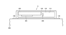
本発明の実施の形態に係る道路用照明装置Aは、道路Rの高欄部900に設置される筐体100と、この筐体100に格納され、道路Rの路面に光を照射する照明部200と、前記筐体100に格納され、道路Rを走行する自動車の速度を検出するセンサ部400と、前記筐体100に格納され、前記センサ部400で検出された自動車の速度が予め設定した速度以下になると発光する注意喚起用発光部300とを備えており、前記注意喚起用発光部300から発せられる光は、照明部200から発せられる光とは色相が異なっている。
A road lighting apparatus A according to an embodiment of the present invention includes a
前記筐体100は、道路Rの高欄部900の頂面に設置されるものであって、ステンレス板で横長の直方体状に形成され、道路Rに面した前面に開口110が開設され、かつ透明な合成樹脂製の透明カバー120で覆われている。
かかる筐体100の底面部の両端部には、筐体100から横方向に突出した平板状の取付脚130が溶接されている。この取付脚130は、高欄部900に筐体100を設置するものである。
The
At both ends of the bottom surface of the
かかる筐体100の内部には、照明部200、センサ部400、注意喚起用発光部300やこれらを制御する制御ユニット500が格納されている。特に、センサ部400のうち、センシング部410は走行する自動車がのぞめるように、前記透明カバー120から覗ける位置に設けられている。
Inside the
前記照明部200は、ライン状のLED素子モジュールであり、筐体100の内部に取り付けられている。この照明部200の光は白色光が望ましい。かかる照明部200からの光は、筐体100の外部に直接向かうのではなく、筐体100の内部に取り付けられた鏡面処理が施された反射板210に向かうようになっている。反射板210は、照明部200からの光を道路Rの路面に向かって反射するようになっている。反射板210は、危険防止のため、照明部200の光が走行中の自動車の運転者に向かって直接照射されることがないようにしている。
The
この照明部200は、1日を3つの時間帯に分割し、その時間帯にあった点灯を行う。昼間帯(日の出〜日没)にはオフされ、夜間帯(日没後〜22時)には100%点灯し、深夜帯(22時〜日の出)には50%点灯を行うのである。
なお、この時間帯の分割は、現地からの外部入力により運用するが、前記制御ユニット500で設定可能で、設置される地域や季節に応じて任意に設定することができ、上記のものに限定されないことはいうまでもない。
なお、100%点灯とは定格電力が供給された場合の点灯状態をいい、50%点灯とはその1/2の点灯状態をいう。
The
This division of time zone is operated by external input from the field, but can be set by the
In addition, 100% lighting means a lighting state when the rated power is supplied, and 50% lighting means a lighting state that is ½ of that.
一方、注意喚起発光部300も、ライン状の白色のLED素子モジュールと、このLED素子モジュールの前面側に設けられる赤色パネルとから構成され、筐体100の内部に取り付けられている。ただし、この注意喚起発光部300から発せられる光は、前記照明部200からの光とは色相が異なり、赤色光となっている。注意喚起発光部300からの光が、照明部200から光と色相が異なれば、注意喚起発光部300から光が照明部200からの光に紛れ込むことがなく、運転者に確実に視認されるようになる。
特に、赤色光は、運転者に対して注意を喚起するのに適している。
On the other hand, the attention
In particular, red light is suitable for alerting the driver.
前記センサ部400は、赤外線センサであるセンシング部410と、このセンシング部410からの信号を受けて、自動車の速度が予め設定された速度以下であるか否かを判断する判断部420とを有している。このセンサ部400も筐体100の内部に格納されている。前記判断部420は、自動車の速度が予め設定された速度以下であると判断すると、制御ユニット500を介して注意喚起発光部300を点灯又は点減させる。なお、注意喚起発光部300の点灯又は点減は、任意に選択可能とする。
The
また、前記判断部420の出力は、前記制御ユニット500を介して注意喚起部発光部300のみならず、照明部200にも導入されている。すなわち、50%点灯を行っている深夜帯に、自動車の速度が予め設定された速度以下になったと判断されると、照明部200は50%点灯から100%点灯に切り替わるのである。
Further, the output of the
ところで、前記予め設定された速度には、渋滞か否かの閾値を用いるとよい。一般的に、一般道路においては走行速度が20kh/h以下、高速道路においては走行速度が40kh/hになると渋滞が発生しているとされる。この速度は、警視庁の交通部交通量統計表で用いられているものであるので、本発明がかかる数値に限定されるものではなく、任意に設定変更が可能である。 By the way, a threshold value indicating whether or not there is a traffic jam may be used for the preset speed. Generally, traffic congestion occurs when the traveling speed is 20 kh / h or less on a general road and the traveling speed is 40 kh / h on a highway. Since this speed is used in the traffic volume statistics table of the Metropolitan Police Department, the present invention is not limited to such a numerical value, and can be arbitrarily changed.
このように構成された道路用照明装置Aは、3〜5mおきに複数台が高欄部900に設置され、すべてが同期して作動するようになっている。
A plurality of road lighting devices A configured in this way are installed in the
このように構成された道路用照明装置の動作は以下の通りである。
(1)昼間帯
昼間帯では、電源断のため、すべての動作はオフされている。
(2)夜間帯
夜間帯では、照明部200は100%点灯している。そして、自動車の速度が予め設定された速度以下になると、すなわち緊急事態が発生したと判断されると、注意喚起発光部300も点灯又は点減される。
そして、自動車の速度が予め設定された速度以上になると、注意喚起発光部300はオフされる。なお、照明部200の100%点灯はそのまま継続される。
(3)深夜帯
深夜帯では、照明部200は50%点灯している。そして、自動車の速度が予め設定された速度以下になると、すなわち緊急事態が発生したと判断されると、注意喚起発光部300は点灯又は点減され、照明部200も100%点灯になる。
そして、自動車の速度が予め設定された速度以上になると、注意喚起発光部300はオフされ、照明部200は100%点灯から50%点灯に復帰する。
なお、自動車の速度が予め設定された速度以下になった場合には、照明部200が100%点灯になるため、渋滞が発生している前方の視認性を向上させることができる。
The operation of the road illumination device thus configured is as follows.
(1) Daytime zone In the daytime zone, all operations are turned off due to power failure.
(2) Night zone In the night zone, the
And if the speed of a motor vehicle becomes more than the preset speed, the alert
(3) Midnight Zone In the late night zone, the
And if the speed of a motor vehicle becomes more than the preset speed, the alert
In addition, when the speed of the automobile is equal to or lower than a preset speed, the
例えば、図4に示すようなカーブの出口側で渋滞が発生しているとする。なお、図4ではC1を渋滞の列の最後尾の自動車を示すものとし、C2をカーブに進入しようとしている自動車とする。
(1)昼間帯
電源断でオフされているので、作動しない。
(2)夜間帯
すべての道路用照明装置Aの照明部200は100%点灯をしている。この状態でカーブの出口側で渋滞が発生しても自動車C2の運転者には視認されない。
しかし、カーブの高欄部900に設置された複数の道路用照明装置Aのうち、出口側の道路用照明装置A1が渋滞を検出する。その結果、すべての道路用照明装置Aが注意喚起発光部300を同期して点灯又は点減させる。
この注意喚起発光部300からの赤色光は、自動車C2の運転者に視認され、自動車C2の速度は運転者により抑制される。なお、注意喚起発光部300が点灯又は点減しても照明部200に変化はない。このため、渋滞の列の最後尾の自動車C1は、自動車C2の運転者によって視認されやすい。
なお、渋滞が解消すると、すべての道路用照明装置Aの注意喚起発光部300はオフされる。
(3)深夜帯
すべての道路用照明装置Aの照明部200は50%点灯をしている。この状態でカーブの出口側で渋滞が発生しても自動車C2の運転者には視認されない。
しかし、カーブの高欄部900に設置された複数の道路用照明装置Aのうち、出口側の道路用照明装置A1が渋滞を検出する。その結果、すべての道路用照明装置Aが照明部200を100%点灯に復させるとともに、注意喚起発光部300を同期して点灯又は点減させる。
この注意喚起発光部300からの赤色光は、自動車C2の運転者に視認され、自動車C2の速度は運転者により抑制される。また、照明部200が100%点灯に復帰するため、渋滞が発生している前方の視認性が向上する。このため、渋滞の列の最後尾の自動車C1は、自動車C2の運転者によって視認されやすい。
なお、渋滞が解消すると、照明部200は50%点灯に復帰するとともに、注意喚起発光部300はオフされる。
For example, it is assumed that there is a traffic jam on the exit side of the curve as shown in FIG. In FIG. 4, C1 represents the last car in the queue of traffic jams, and C2 is the car that is about to enter the curve.
(1) Daytime day It does not work because it is turned off due to power interruption.
(2) Night Zone The
However, among the plurality of road illumination devices A installed in the
The red light from the warning
When the traffic jam is eliminated, the warning
(3) Late night zone The
However, among the plurality of road illumination devices A installed in the
The red light from the warning
When the traffic jam is eliminated, the
すなわち、いずれの時間帯においても渋滞が発生すると、注意喚起発光部300が点灯又は点減し、カーブに進入しようとしている自動車C2の運転者に対して注意を喚起するのである。
特に、この道路用照明装置Aは、カーブにおいて有効である。
すなわち、図4に示すように、カーブに進入する前の自動車C2の運転者からは直接視認できないカーブの先において渋滞が発生している場合には、そのカーブの手前に設置されたすべての道路用照明装置Aの注意喚起発光部300が点灯又は点減することによって、カーブの先で渋滞が発生していることを自動車C2の運転者に対して予告することになる。運転者は、その予告から渋滞の発生を察知できるので、カーブへの進入に際して自車(自動車C2)の速度を抑え、衝突事故の発生を未然に防止することができる。
That is, when a traffic jam occurs in any time zone, the alert
In particular, the road illumination device A is effective in a curve.
That is, as shown in FIG. 4, when there is a traffic jam at the end of the curve that cannot be directly seen by the driver of the car C2 before entering the curve, all roads installed in front of the curve When the warning
カーブにおいて赤色灯が常時点灯又は点減することでカーブの存在をカーブに進入しようとしている自動車の運転者に示すものはすでに存在するが、赤色灯が常時点灯又は点減していると、この運転者は直接視認できないカーブの先において渋滞が発生していても、その情報を受け取ることができないことになる。
これに対して、この道路用照明装置Aであると、渋滞が発生している時のみ、注意喚起発光部300を点灯又は点減させることができるので、運転者に対して渋滞をより認識させやすくなる。
There is already an indication of the existence of the curve to the driver of the car trying to enter the curve by constantly lighting or reducing the red light on the curve. The driver cannot receive the information even if there is a traffic jam ahead of the curve that cannot be directly seen.
On the other hand, in the case of this road lighting device A, the warning
なお、カーブの出口側ではなく入り口側等の他の箇所で事故等が発生し、自動車C1の位置で自動車が停止したり、予め設定された速度以下になると、道路用照明装置Aは上述したカーブの出口側で渋滞が発生したのと同じように作動する。 In addition, when an accident or the like occurs at other places such as the entrance side instead of the exit side of the curve, and the automobile stops at the position of the automobile C1 or falls below a preset speed, the road lighting device A is described above. Operates in the same way as traffic jams occur on the exit side of the curve.
なお、上述した実施の形態では、注意喚起発光部300は赤色の光を発するとしたが、他の色の光であってもよいことはいうまでもない。ただし、照明部200の光に紛れ込まないように、照明部200の発する光とは色相を違うものにする必要がある。
また、注意喚起発光部300は、ライン状のLED素子モジュールとしたが、ライン状ではない他のタイプ、例えば丸形、四角形等であってもよい。
さらに、センサ部400のセンシング部410は赤外線センサであるとしたが、非接触式の速度センサであれば、他のものであってもよいことはいうまでもない。
In the above-described embodiment, the alert
Moreover, although the alert
Furthermore, although the
次に、本発明の他の実施の形態に係る道路用照明装置について説明する。
上述した道路用照明装置Aでは、自動車の速度が予め設定された速度以下になった場合、すなわち渋滞が発生した場合に注意喚起発光部300を点灯又は点減させるものであったが、この道路用照明装置では、自動車の速度が予め設定された速度以上になった場合に注意喚起発光部300を点灯又は点減させるものである。
Next, a road lighting device according to another embodiment of the present invention will be described.
In the above-described road lighting device A, when the speed of the vehicle is equal to or lower than a preset speed, that is, when a traffic jam occurs, the warning
この道路用照明装置における各部の構成は上述したものと同様であるので、その詳細な説明は省略し、動作を説明する。
(1)昼間帯
昼間帯では、昼間帯では、電源断のため、すべての動作はオフされている。
(2)夜間帯
夜間帯では、照明部200は100%点灯している。そして、自動車の速度が予め設定された速度以上になると、注意喚起発光部300も点灯又は点減される。
そして、自動車が予め設定された区間を通過するまで、注意喚起発光部300は点灯又は点減を継続する。なお、照明部200の100%点灯はそのまま継続される。
そして、自動車が予め設定された区間を通過すると、注意喚起発光部300はオフされ、照明部200は100%点灯を継続する。
なお、自動車が予め設定された区間を通過するか否かは、検出された自動車の速度とその区間の距離とから演算される。
(3)深夜帯
深夜帯では、照明部200は50%点灯している。そして、自動車の速度が予め設定された速度以上になると、注意喚起発光部300は点灯又は点減され、照明部200も100%点灯になる。
そして、自動車の速度が予め設定された速度以下になると、注意喚起発光部300はオフされ、照明部200は100%点灯から50%点灯に復帰する。
そして、自動車が予め設定された区間を通過するまで、注意喚起発光部300は点灯又は点減を継続する。なお、照明部200の100%点灯はそのまま継続される。
そして、自動車が予め設定された区間を通過すると、注意喚起発光部300はオフされ、照明部200は50%点灯に復帰する。
なお、自動車が予め設定された区間を通過するか否かは、検出された自動車の速度とその区間の距離とから演算される。
Since the configuration of each part in the road lighting device is the same as that described above, the detailed description thereof will be omitted and the operation will be described.
(1) Daytime zone In the daytime zone, all operations are turned off in the daytime zone due to power interruption.
(2) Night zone In the night zone, the
And the alerting
And if a motor vehicle passes through the preset area, the alert
Whether or not the automobile passes through a preset section is calculated from the detected speed of the automobile and the distance of the section.
(3) Midnight Zone In the late night zone, the
And if the speed of a motor vehicle becomes below the preset speed, the alert
And the alerting
When the vehicle passes through a preset section, the alert
Whether or not the automobile passes through a preset section is calculated from the detected speed of the automobile and the distance of the section.
かかる道路用照明装置であると、このように自動車の速度が予め設定された速度(例えば、制限速度)以上で進入した場合には、速度超過による危険性を運転者に対して注意喚起することができ、交通事故の低減に寄与することができるのである。 In such a road lighting device, when the speed of the vehicle enters at a speed higher than a preset speed (for example, a speed limit), the driver is warned of the danger of overspeeding. Can contribute to reducing traffic accidents.
なお、上述した説明では、昼間帯においては、電源断ですべての動作がオフされているとしたが、本発明はこれに限定されることはない。
すなわち、昼間帯であっても、自動車の速度が予め設定された速度以下になると、すなわち緊急事態が発生したと判断されると、注意喚起発光部300も点灯又は点減され、自動車の速度が予め設定された速度以上になると、注意喚起発光部300はオフされるようにしてもよい。
なお、照明部200は点灯されていても消灯されていてもよい。
In the above description, in the daytime period, it is assumed that all the operations are turned off due to power interruption, but the present invention is not limited to this.
That is, even in the daytime period, when the speed of the automobile is equal to or lower than a preset speed, that is, when it is determined that an emergency has occurred, the alert
The
100 筐体
200 照明部
300 注意喚起発光部
400 センサ部
900 高欄部
DESCRIPTION OF
Claims (3)
Priority Applications (1)
| Application Number | Priority Date | Filing Date | Title |
|---|---|---|---|
| JP2011004202A JP2012146527A (en) | 2011-01-12 | 2011-01-12 | Road lighting system |
Applications Claiming Priority (1)
| Application Number | Priority Date | Filing Date | Title |
|---|---|---|---|
| JP2011004202A JP2012146527A (en) | 2011-01-12 | 2011-01-12 | Road lighting system |
Publications (1)
| Publication Number | Publication Date |
|---|---|
| JP2012146527A true JP2012146527A (en) | 2012-08-02 |
Family
ID=46789913
Family Applications (1)
| Application Number | Title | Priority Date | Filing Date |
|---|---|---|---|
| JP2011004202A Pending JP2012146527A (en) | 2011-01-12 | 2011-01-12 | Road lighting system |
Country Status (1)
| Country | Link |
|---|---|
| JP (1) | JP2012146527A (en) |
Cited By (2)
| Publication number | Priority date | Publication date | Assignee | Title |
|---|---|---|---|---|
| JP2016009563A (en) * | 2014-06-24 | 2016-01-18 | 西日本高速道路株式会社 | Warning attention device for tunnel and warning attention system with the warning attention device |
| CN110992719A (en) * | 2019-12-31 | 2020-04-10 | 江苏恒达微波技术开发有限公司 | Waterproof traffic signal lamp of easy dismouting |
Citations (9)
| Publication number | Priority date | Publication date | Assignee | Title |
|---|---|---|---|---|
| JPS49112091A (en) * | 1973-02-28 | 1974-10-25 | ||
| JPH05315082A (en) * | 1992-05-14 | 1993-11-26 | Matsushita Electric Ind Co Ltd | Control device for lighting tunnel inside |
| JPH11120484A (en) * | 1997-10-15 | 1999-04-30 | Matsushita Electric Works Ltd | Illuminating device |
| JP2001243599A (en) * | 2000-02-29 | 2001-09-07 | Sumitomo Electric Ind Ltd | Vehicle traveling supporting system |
| JP2004259248A (en) * | 2003-03-25 | 2004-09-16 | Global Com:Kk | Road lighting control system and method |
| JP2005327748A (en) * | 2005-08-08 | 2005-11-24 | Toshiba Lighting & Technology Corp | Balustrade illumination fixture |
| WO2006008825A1 (en) * | 2004-07-16 | 2006-01-26 | Fourie | Road condition informing system and road condition informing method |
| JP2006147418A (en) * | 2004-11-22 | 2006-06-08 | Toshiba Lighting & Technology Corp | Road luminaire |
| JP2008234489A (en) * | 2007-03-22 | 2008-10-02 | Toshiba Lighting & Technology Corp | Traffic congestion informing system |
-
2011
- 2011-01-12 JP JP2011004202A patent/JP2012146527A/en active Pending
Patent Citations (9)
| Publication number | Priority date | Publication date | Assignee | Title |
|---|---|---|---|---|
| JPS49112091A (en) * | 1973-02-28 | 1974-10-25 | ||
| JPH05315082A (en) * | 1992-05-14 | 1993-11-26 | Matsushita Electric Ind Co Ltd | Control device for lighting tunnel inside |
| JPH11120484A (en) * | 1997-10-15 | 1999-04-30 | Matsushita Electric Works Ltd | Illuminating device |
| JP2001243599A (en) * | 2000-02-29 | 2001-09-07 | Sumitomo Electric Ind Ltd | Vehicle traveling supporting system |
| JP2004259248A (en) * | 2003-03-25 | 2004-09-16 | Global Com:Kk | Road lighting control system and method |
| WO2006008825A1 (en) * | 2004-07-16 | 2006-01-26 | Fourie | Road condition informing system and road condition informing method |
| JP2006147418A (en) * | 2004-11-22 | 2006-06-08 | Toshiba Lighting & Technology Corp | Road luminaire |
| JP2005327748A (en) * | 2005-08-08 | 2005-11-24 | Toshiba Lighting & Technology Corp | Balustrade illumination fixture |
| JP2008234489A (en) * | 2007-03-22 | 2008-10-02 | Toshiba Lighting & Technology Corp | Traffic congestion informing system |
Cited By (2)
| Publication number | Priority date | Publication date | Assignee | Title |
|---|---|---|---|---|
| JP2016009563A (en) * | 2014-06-24 | 2016-01-18 | 西日本高速道路株式会社 | Warning attention device for tunnel and warning attention system with the warning attention device |
| CN110992719A (en) * | 2019-12-31 | 2020-04-10 | 江苏恒达微波技术开发有限公司 | Waterproof traffic signal lamp of easy dismouting |
Similar Documents
| Publication | Publication Date | Title |
|---|---|---|
| US9990847B2 (en) | Traffic accident occurrence notification system using LED display lamps | |
| KR101810662B1 (en) | Crosswalk safety walking system with a signal lamp | |
| EP3126194B1 (en) | A warning system for a vehicle and a vehicle comprising such a warning system | |
| US20050117364A1 (en) | Method and apparatus for projecting a turn signal indication | |
| WO2020096060A1 (en) | Motorcycle and motorcycle lighting device | |
| KR20090010935A (en) | Apparatus for protecting pedestrian | |
| US10773644B2 (en) | Warning system for a turning vehicle and a vehicle comprising such a warning system | |
| JP2006209325A (en) | Vehicle alarm device and method for producing alarm from vehicle | |
| US7808376B2 (en) | Continuous enhanced vehicle hazard warning lights | |
| JP2012146527A (en) | Road lighting system | |
| KR100977609B1 (en) | Method for controlling light emitting source of median strip | |
| CN108367792B (en) | Two-wheeled motor vehicle and lamp opening device of two-wheeled motor vehicle | |
| ES2539876B1 (en) | Device for the prevention of accidents due to rear-end collision and its operating system | |
| JP3185192U (en) | Transverse display device | |
| KR20150108954A (en) | Safety apparatus of a walk-way and operation method of the same | |
| JP2001338778A (en) | Lighting system | |
| JP2006048955A (en) | Braking warning device of vehicle | |
| JP5770687B2 (en) | Safety lamp | |
| KR200431152Y1 (en) | Apparatus for displaying state of reducing speed for use in vehicle | |
| KR100224062B1 (en) | A night safety equipment of car for a foot passenger | |
| KR100644352B1 (en) | Safety Plate Sounding Warnings for Vehicles Approaching from Behind | |
| KR20170138154A (en) | Line crosswalk | |
| KR0127547Y1 (en) | Safety device for a car | |
| JP2020175838A (en) | Front crossing pedestrian warning lamp system for vehicle | |
| KR20050100144A (en) | Confirming apparatus for upward light of rear vehicle and the method thereof |
Legal Events
| Date | Code | Title | Description |
|---|---|---|---|
| A621 | Written request for application examination |
Free format text: JAPANESE INTERMEDIATE CODE: A621 Effective date: 20131023 |
|
| A977 | Report on retrieval |
Free format text: JAPANESE INTERMEDIATE CODE: A971007 Effective date: 20140612 |
|
| A131 | Notification of reasons for refusal |
Free format text: JAPANESE INTERMEDIATE CODE: A131 Effective date: 20140617 |
|
| A521 | Written amendment |
Free format text: JAPANESE INTERMEDIATE CODE: A523 Effective date: 20140818 |
|
| A02 | Decision of refusal |
Free format text: JAPANESE INTERMEDIATE CODE: A02 Effective date: 20140909 |