JP2012144386A - Apparatus for producing silicon carbide single crystal - Google Patents
Apparatus for producing silicon carbide single crystal Download PDFInfo
- Publication number
- JP2012144386A JP2012144386A JP2011002292A JP2011002292A JP2012144386A JP 2012144386 A JP2012144386 A JP 2012144386A JP 2011002292 A JP2011002292 A JP 2011002292A JP 2011002292 A JP2011002292 A JP 2011002292A JP 2012144386 A JP2012144386 A JP 2012144386A
- Authority
- JP
- Japan
- Prior art keywords
- single crystal
- pedestal portion
- gas
- source gas
- silicon carbide
- Prior art date
- Legal status (The legal status is an assumption and is not a legal conclusion. Google has not performed a legal analysis and makes no representation as to the accuracy of the status listed.)
- Granted
Links
- 239000013078 crystal Substances 0.000 title claims abstract description 229
- 229910010271 silicon carbide Inorganic materials 0.000 title claims description 112
- HBMJWWWQQXIZIP-UHFFFAOYSA-N silicon carbide Chemical compound [Si+]#[C-] HBMJWWWQQXIZIP-UHFFFAOYSA-N 0.000 title claims description 112
- NJPPVKZQTLUDBO-UHFFFAOYSA-N novaluron Chemical group C1=C(Cl)C(OC(F)(F)C(OC(F)(F)F)F)=CC=C1NC(=O)NC(=O)C1=C(F)C=CC=C1F NJPPVKZQTLUDBO-UHFFFAOYSA-N 0.000 claims abstract description 159
- 238000010438 heat treatment Methods 0.000 claims abstract description 81
- 238000001816 cooling Methods 0.000 claims abstract description 24
- 238000004519 manufacturing process Methods 0.000 claims description 52
- 238000010790 dilution Methods 0.000 claims description 21
- 239000012895 dilution Substances 0.000 claims description 21
- 238000005530 etching Methods 0.000 claims description 21
- 239000000758 substrate Substances 0.000 claims description 4
- 238000009795 derivation Methods 0.000 claims description 3
- 229910052710 silicon Inorganic materials 0.000 claims description 3
- XUIMIQQOPSSXEZ-UHFFFAOYSA-N Silicon Chemical compound [Si] XUIMIQQOPSSXEZ-UHFFFAOYSA-N 0.000 claims 2
- 238000003763 carbonization Methods 0.000 claims 2
- 239000010703 silicon Substances 0.000 claims 2
- 238000009826 distribution Methods 0.000 abstract description 34
- 230000000694 effects Effects 0.000 abstract description 9
- 235000012431 wafers Nutrition 0.000 abstract description 5
- 230000005855 radiation Effects 0.000 abstract 1
- 239000007789 gas Substances 0.000 description 154
- 239000002994 raw material Substances 0.000 description 30
- 239000011810 insulating material Substances 0.000 description 21
- OKTJSMMVPCPJKN-UHFFFAOYSA-N Carbon Chemical compound [C] OKTJSMMVPCPJKN-UHFFFAOYSA-N 0.000 description 13
- 229910002804 graphite Inorganic materials 0.000 description 12
- 239000010439 graphite Substances 0.000 description 12
- NFFIWVVINABMKP-UHFFFAOYSA-N methylidynetantalum Chemical compound [Ta]#C NFFIWVVINABMKP-UHFFFAOYSA-N 0.000 description 12
- 229910003468 tantalcarbide Inorganic materials 0.000 description 12
- 238000011144 upstream manufacturing Methods 0.000 description 7
- 230000004907 flux Effects 0.000 description 6
- 239000002245 particle Substances 0.000 description 4
- 239000012159 carrier gas Substances 0.000 description 3
- 230000002093 peripheral effect Effects 0.000 description 3
- ATUOYWHBWRKTHZ-UHFFFAOYSA-N Propane Chemical compound CCC ATUOYWHBWRKTHZ-UHFFFAOYSA-N 0.000 description 2
- BLRPTPMANUNPDV-UHFFFAOYSA-N Silane Chemical compound [SiH4] BLRPTPMANUNPDV-UHFFFAOYSA-N 0.000 description 2
- 230000004323 axial length Effects 0.000 description 2
- 229910052799 carbon Inorganic materials 0.000 description 2
- 230000006698 induction Effects 0.000 description 2
- 238000000034 method Methods 0.000 description 2
- 239000004065 semiconductor Substances 0.000 description 2
- 229910000077 silane Inorganic materials 0.000 description 2
- 239000004215 Carbon black (E152) Substances 0.000 description 1
- 239000000498 cooling water Substances 0.000 description 1
- 238000005336 cracking Methods 0.000 description 1
- 238000010586 diagram Methods 0.000 description 1
- 229930195733 hydrocarbon Natural products 0.000 description 1
- 150000002430 hydrocarbons Chemical class 0.000 description 1
- 239000011261 inert gas Substances 0.000 description 1
- 239000000463 material Substances 0.000 description 1
- 239000001294 propane Substances 0.000 description 1
- 239000010453 quartz Substances 0.000 description 1
- 238000001953 recrystallisation Methods 0.000 description 1
- VYPSYNLAJGMNEJ-UHFFFAOYSA-N silicon dioxide Inorganic materials O=[Si]=O VYPSYNLAJGMNEJ-UHFFFAOYSA-N 0.000 description 1
- 238000000859 sublimation Methods 0.000 description 1
- 230000008022 sublimation Effects 0.000 description 1
Images

Abstract
Description
本発明は、炭化珪素(以下、SiCという)単結晶の製造装置に関するものである。 The present invention relates to a silicon carbide (hereinafter referred to as SiC) single crystal manufacturing apparatus.
従来より、SiC単結晶の製造として、例えば特許文献1に示すようなガス供給式等のSiC単結晶製造装置が用いられている。ガス供給式のSiC単結晶製造装置では、導入管を通じてSiCの原料ガスを加熱容器内に導入すると共に加熱容器にて原料ガスを分解し、分解した原料ガスを反応容器に備えられた種結晶に導くことで、種結晶の表面にSiC単結晶を成長させる。
Conventionally, for example, a SiC single crystal manufacturing apparatus such as a gas supply type as shown in
上記のようなSiC単結晶製造装置において、1ラン当りのウェハの取れ数を多くするために、SiC単結晶の成長インゴットの長尺化が望まれている。ところが、SiC単結晶を長尺成長させると、種結晶が貼り付けられる台座部とSiC単結晶の成長表面との温度差が大きくなり、インゴット割れが引き起こされる。そこで、複数枚の種結晶を配置し、全種結晶上に成長したトータルのSiC単結晶の成長量が一枚の種結晶のみを用いて長尺成長させたときの成長量に達するようにして、1ラン当りのウェハ取れ数を多くすることが考えられる。 In the SiC single crystal manufacturing apparatus as described above, in order to increase the number of wafers taken per run, it is desired to increase the length of the SiC single crystal growth ingot. However, when the SiC single crystal is grown long, the temperature difference between the pedestal to which the seed crystal is attached and the growth surface of the SiC single crystal increases, and ingot cracking is caused. Therefore, a plurality of seed crystals are arranged so that the growth amount of the total SiC single crystal grown on all the seed crystals reaches the growth amount when the long growth is performed using only one seed crystal. It is conceivable to increase the number of wafers taken per run.
しかしながら、複数枚の種結晶を配置してSiC単結晶を成長させる場合、単に有底円筒状で構成される反応容器の底面に複数枚の種結晶を配置したのでは、温度分布等の影響でSiC単結晶の成長速度に面内分布ができ、面内において均一に成長させることができないことが判った。 However, when growing a SiC single crystal by arranging a plurality of seed crystals, simply placing a plurality of seed crystals on the bottom surface of a reaction vessel having a bottomed cylindrical shape is affected by temperature distribution and the like. It was found that the growth rate of the SiC single crystal has an in-plane distribution and cannot be grown uniformly in the plane.
一方、円筒状の反応容器の側壁面に対して種結晶を複数枚貼り付けること、つまり種結晶の表面がSiC単結晶製造装置の中心軸に対して平行となるように配置して、SiC単結晶を成長させることも考えられる。ところが、この場合、原料ガスの流動経路の上流側から下流側に向かって温度分布ができ、種結晶の面内において温度分布ができる。このため、単に円筒状の反応容器の側壁に種結晶を貼り付けたのでは、SiC単結晶の成長速度に面内分布ができ、面内において均一に成長させることができない。 On the other hand, a plurality of seed crystals are affixed to the side wall surface of the cylindrical reaction vessel, that is, the seed crystals are arranged so that the surface of the seed crystals is parallel to the central axis of the SiC single crystal manufacturing apparatus. It is also conceivable to grow crystals. However, in this case, temperature distribution can be made from the upstream side to the downstream side of the flow path of the source gas, and temperature distribution can be made in the plane of the seed crystal. For this reason, if the seed crystal is simply pasted on the side wall of the cylindrical reaction vessel, the growth rate of the SiC single crystal can be distributed in-plane and cannot be grown uniformly in the plane.
本発明は上記点に鑑みて、複数枚の種結晶に対して同時にSiC単結晶を成長させることができ、かつ、SiC単結晶の成長速度を面内においてより均一にできるSiC単結晶製造装置を提供することを目的とする。 In view of the above points, the present invention provides a SiC single crystal manufacturing apparatus capable of simultaneously growing a SiC single crystal on a plurality of seed crystals and making the growth rate of the SiC single crystal more uniform in the plane. The purpose is to provide.
上記目的を達成するため、請求項1に記載の発明では、原料ガス(3)の導入導出が行え、内部空間の圧力を真空引きすることにより減圧できる構造とされた真空容器(6)と、中空円筒状部材(8a)を有して構成され、真空容器(6)内に配置され、原料ガス(3)の加熱を行う加熱容器(8)と、真空容器(6)内において、加熱容器(8)よりも原料ガス(3)の流動経路下流側に配置され、種結晶(5)が貼り付けられる台座部(9)とを有し、真空容器(6)には、台座部(9)の周囲を囲む位置に、台座部(9)の外壁面を冷却する冷却機構(6a)が備えられ、台座部(9)は、加熱容器(8)における中空円筒状部材(8a)のうちの原料ガス(3)の流動経路下流側の端部に配置され、該中空円筒状部材(8a)の中心軸に対して内壁面が傾斜するように該台座部(9)の内径が原料ガス(3)の流動経路下流側に向けて縮小させられ、内壁面に種結晶(5)が貼り付けられる面が複数備えられていることを特徴としている。
In order to achieve the above object, in the invention described in
このように、中空円筒状部材(8a)の中心軸に対して内壁面を傾斜させた台座部(9)を備え、この台座部(9)の内壁面に備えた複数の平坦面に種結晶(5)を配置することで、複数の種結晶(5)の表面上にSiC単結晶を成長させるようにしている。これにより、複数の種結晶(5)に対して同時にSiC単結晶を成長させられるため、1ラン当たりのウェハの取れ数を多くすることが可能となる。そして、種結晶(5)が配置される台座部(9)の内壁面を中空円筒状部材(8a)の中心軸に対して傾斜させることで、台座部(9)の裏面からの冷却と、加熱容器(8)からの輻射熱効果により、種結晶(5)の表面での温度分布をほぼ均一にできる。したがって、SiC単結晶を面内において均一に成長させることが可能となる。そして、真空容器(6)に冷却機構(6a)を備えていることから、より台座部(9)の裏面からの冷却を行うことが可能となり、台座部(9)内での温度分布が調整し易くなり、台座部(9)内で等温分布が台座部(9)の内壁面とほぼ平行となるように制御し易くなる。これにより、よりSiC単結晶を面内において均一に成長させることが可能となる。 Thus, the pedestal portion (9) whose inner wall surface is inclined with respect to the central axis of the hollow cylindrical member (8a) is provided, and seed crystals are formed on a plurality of flat surfaces provided on the inner wall surface of the pedestal portion (9). By arranging (5), a SiC single crystal is grown on the surfaces of the plurality of seed crystals (5). Thereby, since the SiC single crystal can be grown simultaneously on the plurality of seed crystals (5), it is possible to increase the number of wafers taken per run. And by inclining the inner wall surface of the pedestal part (9) where the seed crystal (5) is arranged with respect to the central axis of the hollow cylindrical member (8a), cooling from the back surface of the pedestal part (9), Due to the effect of radiant heat from the heating container (8), the temperature distribution on the surface of the seed crystal (5) can be made substantially uniform. Therefore, the SiC single crystal can be grown uniformly in the plane. And since the cooling mechanism (6a) is provided in the vacuum vessel (6), it becomes possible to cool from the back surface of the base part (9), and the temperature distribution in the base part (9) is adjusted. This makes it easy to control the isothermal distribution in the pedestal portion (9) so as to be substantially parallel to the inner wall surface of the pedestal portion (9). This makes it possible to grow a SiC single crystal more uniformly in the plane.
請求項2に記載の発明では、台座部(9)には、原料ガス(3)の流動方向に沿って種結晶(5)が配置される面が多段備えられていることを特徴としている。
The invention according to
このようにすれば、より多数枚の種結晶(5)に対して同時にSiC単結晶を成長させられる。これにより、よりSiC単結晶の収率を向上させることが可能となる。 In this way, a SiC single crystal can be grown simultaneously on a larger number of seed crystals (5). Thereby, the yield of the SiC single crystal can be further improved.
請求項3に記載の発明では、台座部(9)の内壁面には、種結晶(5)の周囲を囲む、所定高さの整流板(9a)が備えられていることを特徴としている。
The invention according to
このような整流板(9a)を備えることにより、種結晶(5)の周囲において原料ガス(3)を整流でき、よりSiC単結晶を面内において均一に成長させることが可能となる。 By providing such a rectifying plate (9a), the source gas (3) can be rectified around the seed crystal (5), and a SiC single crystal can be more uniformly grown in the plane.
請求項4に記載の発明では、台座部(9)には、該台座部(9)における原料ガス(3)の流動方向下流側に希釈ガスとエッチングガスの少なくとも一方を導入するガス流路(13)が備えられていることを特徴としている。
In the invention according to
このように、ガス流路(13)を備えて希釈ガスとエッチングガスの少なくとも一方を導入できるようにすると、台座部(9)における原料ガス(3)の流動方向下流側での多結晶の付着を防止することが可能となる。すなわち、台座部(9)における原料ガス(3)の流動方向下流側では、流路の断面積が小さくなるので、流束が上がり、多結晶が付着して閉塞し易くなる。このため、ガス流路(13)から希釈ガスとエッチングガスの少なくとも一方が導入されるようにすることで、原料ガス(3)を希釈したり、多結晶が付着しようとしてもそれをエッチングすることで、多結晶が付着することを抑制することが可能となる。 As described above, when the gas flow path (13) is provided so that at least one of the dilution gas and the etching gas can be introduced, the polycrystal adheres on the downstream side in the flow direction of the source gas (3) in the pedestal portion (9). Can be prevented. That is, on the downstream side of the flow direction of the source gas (3) in the pedestal portion (9), the cross-sectional area of the flow path is small, so that the flux is increased and polycrystals are attached and easily blocked. Therefore, by introducing at least one of a dilution gas and an etching gas from the gas flow path (13), the source gas (3) is diluted or etched even if polycrystals are to be deposited. Thus, it is possible to suppress the adhesion of polycrystals.
請求項5に記載の発明では、原料ガス(3)の導入導出が行え、内部空間の圧力を真空引きすることにより減圧できる構造とされた真空容器(6)と、中空円筒状部材(8a)を有して構成され、真空容器(6)内に配置され、原料ガス(3)の加熱を行う加熱容器(8)と、加熱容器(8)における原料ガス(3)の流動経路下流側に配置され、該流動経路下流側に向かって徐々に外径が拡大された円錐形状で、外壁面に種結晶(5)が貼り付けられる台座部(9)とを有し、台座部(9)には、種結晶(5)の裏面側から台座部(9)を冷却する冷却機構(9b)が備えられ、台座部(9)の外壁面には、種結晶(5)が貼り付けられる面が複数備えられていることを特徴としている。
In the invention according to
このように、台座部(9)の外壁面を加熱容器(8)の中心軸に対して傾斜させるようにしても、種結晶(5)の表面での温度分布がほぼ均一となる。すなわち、台座部(9)のうち種結晶(5)の裏面側からの冷却と、加熱容器(8)からの輻射熱効果により、台座部(9)内での温度分布が台座部(9)の内壁面とほぼ平行となり、その上に貼り付けられた種結晶(5)の表面での温度分布もほぼ均一となる。したがって、SiC単結晶を面内において均一に成長させることが可能となる。これにより、請求項1と同様の効果を得ることが可能となる。 Thus, even if the outer wall surface of the pedestal portion (9) is inclined with respect to the central axis of the heating vessel (8), the temperature distribution on the surface of the seed crystal (5) becomes substantially uniform. That is, the temperature distribution in the pedestal (9) of the pedestal (9) is reduced by the cooling from the back side of the seed crystal (5) in the pedestal (9) and the radiant heat effect from the heating container (8). The temperature distribution on the surface of the seed crystal (5) affixed on the inner wall surface is substantially parallel to the inner wall surface. Therefore, the SiC single crystal can be grown uniformly in the plane. Thus, the same effect as in the first aspect can be obtained.
請求項6に記載の発明では、台座部(9)には、原料ガス(3)の流動方向に沿って種結晶(5)が配置される面が多段備えられていることを特徴としている。
The invention according to
このようにすれば、より多数枚の種結晶(5)に対して同時にSiC単結晶を成長させられる。これにより、よりSiC単結晶の収率を向上させることが可能となる。 In this way, a SiC single crystal can be grown simultaneously on a larger number of seed crystals (5). Thereby, the yield of the SiC single crystal can be further improved.
請求項7に記載の発明では、台座部(9)の内壁面には、種結晶(5)の周囲を囲む、所定高さの整流板(9a)が備えられていることを特徴としている。
The invention according to
このような整流板(9a)を備えることにより、種結晶(5)の周囲において原料ガス(3)を整流でき、よりSiC単結晶を面内において均一に成長させることが可能となる。 By providing such a rectifying plate (9a), the source gas (3) can be rectified around the seed crystal (5), and a SiC single crystal can be more uniformly grown in the plane.
請求項8に記載の発明では、加熱容器(8)には、台座部(9)の周囲において希釈ガスとエッチングガスの少なくとも一方を導入する第1ガス流路(13b)が備えられており、台座部(9)には、該台座部(9)における原料ガス(3)の流動方向下流側に希釈ガスとエッチングガスの少なくとも一方を導入する第2ガス流路(13c)が備えられていることを特徴としている。
In the invention according to
このように、第1、第2ガス流路(13b、13c)を備えて希釈ガスとエッチングガスの少なくとも一方を導入できるようにすると、台座部(9)の周囲および台座部(9)における原料ガス(3)の流動方向下流側での多結晶の付着を防止することが可能となる。すなわち、台座部(9)の周囲および台座部(9)における原料ガス(3)の流動方向下流側では、流路の断面積が小さくなるので、流束が上がり、多結晶が付着して閉塞し易くなる。このため、ガス流路(13)から希釈ガスとエッチングガスの少なくとも一方が導入されるようにすることで、原料ガス(3)を希釈したり、多結晶が付着しようとしてもそれをエッチングすることで、多結晶が付着することを抑制することが可能となる。 As described above, when the first and second gas flow paths (13b, 13c) are provided so that at least one of the dilution gas and the etching gas can be introduced, the raw material around the pedestal portion (9) and in the pedestal portion (9). It is possible to prevent the polycrystal from adhering to the downstream side in the flow direction of the gas (3). That is, since the cross-sectional area of the flow path is small around the pedestal portion (9) and on the downstream side in the flow direction of the raw material gas (3) in the pedestal portion (9), the flux is increased and polycrystals adhere and block. It becomes easy to do. Therefore, by introducing at least one of a dilution gas and an etching gas from the gas flow path (13), the source gas (3) is diluted or etched even if polycrystals are to be deposited. Thus, it is possible to suppress the adhesion of polycrystals.
なお、上記各手段の括弧内の符号は、後述する実施形態に記載の具体的手段との対応関係を示すものである。 In addition, the code | symbol in the bracket | parenthesis of each said means shows the correspondence with the specific means as described in embodiment mentioned later.
以下、本発明の実施形態について図に基づいて説明する。なお、以下の各実施形態相互において、互いに同一もしくは均等である部分には、図中、同一符号を付してある。 Hereinafter, embodiments of the present invention will be described with reference to the drawings. In the following embodiments, the same or equivalent parts are denoted by the same reference numerals in the drawings.
(第1実施形態)
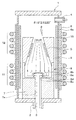
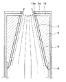
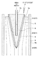
図1に、本実施形態にかかるSiC単結晶製造装置1の断面図を示す。以下、この図を参照してSiC単結晶製造装置1の構造について説明する。
(First embodiment)
FIG. 1 shows a cross-sectional view of an SiC single
図1に示すSiC単結晶製造装置1は、底部に備えられた流入口2を通じてキャリアガスと共にSiおよびCを含有するSiCの原料ガス3(例えば、シラン(SiH4)等のシラン系ガスとプロパン(C3H8)等の炭化水素系ガスの混合ガス)を供給し、上部の流出口4を通じて排出することで、SiC単結晶製造装置1内に配置したSiC単結晶基板からなる円形状の種結晶5上にSiC単結晶を結晶成長させるものである。
A SiC single
SiC単結晶製造装置1には、真空容器6、第1断熱材7、加熱容器8、台座部9、第2断熱材10および第1、第2加熱装置11、12が備えられている。
The SiC single
真空容器6は、石英管などで構成され、中空円筒状を為しており、キャリアガスや原料ガス3の導入導出が行え、かつ、SiC単結晶製造装置1の他の構成要素を収容すると共に、その収容している内部空間の圧力を真空引きすることにより減圧できる構造とされている。この真空容器6の底部に原料ガス3の流入口2が設けられ、上部(具体的には側壁の上方位置)に原料ガス3の流出口4が設けられている。また、真空容器6の側壁内には、冷却水などによる冷却機構6aが備えられており、この冷却機構6aによってSiC単結晶製造装置1の周囲が冷却できるようになっている。
The
第1断熱材7は、円筒等の筒形状を為しており、真空容器6に対して同軸的に配置され、中空部により原料ガス導入管7aを構成している。第1断熱材7は、例えば黒鉛や表面をTaC(炭化タンタル)にてコーティングした黒鉛などで構成される。
The first
加熱容器8は、例えば黒鉛や表面をTaC(炭化タンタル)にてコーティングした黒鉛などで構成されている。この加熱容器8により、流入口2から供給された原料ガス3を種結晶5に導くまでに、原料ガス3に含まれたパーティクルを排除しつつ、原料ガス3を分解している。具体的には、加熱容器8は、有底円筒状部材8aと邪魔板8bとを有して構成されている。
The
有底円筒状部材8aは、中空円筒状部材を構成するものであり、その中心軸がSiC単結晶製造装置1の中心軸と同軸とされている。この有底円筒状部材8aの底部における中央位置には、底部に第1断熱材7の中空部と連通させられるガス導入口8cが備えられ、第1断熱材7の中空部を通過してきた原料ガス3がガス導入口8cを通じて加熱容器8内に導入される。
The bottomed
邪魔板8bは、ガス導入口8cを塞ぐように配置されている。この邪魔板8bに原料ガス3が衝突することで原料ガス3の流動経路が曲げられ、原料ガス3に含まれるパーティクルの排除と原料ガス3のミキシングが行われると共に、未分解の原料ガス3が種結晶5側に供給されることが抑制されている。例えば、邪魔板8bは、有底円筒状で、側壁に複数の連通孔8dが形成された構造とされ、邪魔板8bの開口部側、つまり底部と反対側の端部が加熱容器8の底部のガス導入口8cに向けて配置される。このような構造の場合、ガス導入口8cから導入された原料ガス3が邪魔板8bの底面に衝突するため、邪魔板8bに衝突したパーティクルが加熱容器8の底部に落下して原料ガス3から排除される。そして、流動経路が加熱容器8の軸方向と平行な方向から垂直な方向に変えられた原料ガス3が、連通孔8dを通じて加熱容器8における邪魔板8bよりも流動経路下流側に導かれる。
The
台座部9は、例えば黒鉛や表面をTaC(炭化タンタル)にてコーティングした黒鉛、もしくはカーボン断熱材などで構成されている。台座9は、中空形状で構成された円筒部材とされ、その中心軸が加熱容器8の中心軸と同軸上に配置され、一端側が有底円筒状部材8aの開口端側に接続されている。この台座部9の内壁面に種結晶5が貼り付けられ、台座部9の中空部を反応室として種結晶5の表面にSiC単結晶を成長させる。
The
この台座部9は、外径は一定とされているが、内径が原料ガス3の流動経路下流側に向かって徐々に縮小されている。このため、台座部9の厚みは、原料ガス3の流動経路下流側に向かって徐々に厚くなっている。また、原料ガス3の流動経路の断面積が徐々に縮小され、台座部9の内壁面によって原料ガス3の流束が徐々に絞られる。また、台座部9の内壁面は基本的には円錐台形状とされているが、種結晶5が配置される位置において部分的に円形状の平坦面とされ、これが種結晶5の貼付面とされる。この平坦面は、台座部9の内壁面の複数箇所に備えられ、周方向において等間隔に並べられている。
The
このように、台座部9の内壁面のうちの平坦面に種結晶5が貼り付けられることで、種結晶5が加熱容器8の中心軸に対して傾斜した状態で配置される。台座部9の内壁面が加熱容器8の中心軸に対して成す角度θは、原料ガス3の流量に応じて適宜設定される。例えば、原料ガス3としてSiH4、C3H8、H2を用い、これらの流量をSiH4:1slm、C3H8:333sccm、H2:10〜15slmとする場合には、角度θが13°≦θ≦23°に設定されると好ましい。
In this way, the
第2断熱材10は、真空容器6の側壁面に沿って配置され、中空円筒状を為している。この第2断熱材10により、ほぼ第1断熱材7や加熱容器8が囲まれている。この第2断熱材10も、例えば黒鉛や表面をTaC(炭化タンタル)にてコーティングされた黒鉛などで構成される。
The second
第1、第2加熱装置11、12は、例えば誘導加熱用コイルやヒータなどで構成され、真空容器6の周囲を囲むように配置されている。これら第1、第2加熱装置11、12は、それぞれ独立して温度制御できるように構成されている。このため、より細やかな温度制御を行うことができる。第1加熱装置11は、加熱容器8のうちの有底円筒状部材8aや邪魔板8bと対応した位置に配置されている。第2加熱装置12は、台座部9に対応した位置に配置されている。このような配置とされているため、第1、第2加熱装置11、12を制御することにより、反応室の温度分布をSiC単結晶の成長に適した温度に調整できると共に、加熱容器8のうちの有底円筒状部材8aや邪魔板8bの温度をパーティクルの除去に適した温度に調整できる。
The first and
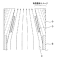
続いて、このように構成されたSiC単結晶製造装置1を用いたSiC単結晶の製造方法について説明する。図2は、図1に示すSiC単結晶製造装置1を用いたSiC単結晶の製造中における台座部9内の等温分布を示したイメージ図である。
Then, the manufacturing method of the SiC single crystal using the SiC single
まず、第1、第2加熱装置11、12を制御し、所望の温度分布を付ける。すなわち、種結晶5の表面において原料ガス3が再結晶化されることでSiC単結晶が成長しつつ、加熱容器8内において再結晶化レートよりも昇華レートの方が高くなる温度となるようにする。例えば、加熱容器8の温度が2400℃程度、台座部9の温度が2200℃程度となるように第1、第2加熱装置11、12を制御する。
First, the first and
また、真空容器6を所望圧力にしつつ、必要に応じてArガスなどの不活性ガスによるキャリアガスを導入しながら原料ガス導入管7aを通じて原料ガス3としてSiH4、C3H8、H2を導入する。これにより、図1および図2中の矢印で示したように原料ガス3が流動し、種結晶5に供給されてSiC単結晶を成長させることができる。
Further, SiH 4 , C 3 H 8 , and H 2 are supplied as the
このとき、本実施形態では、台座部9の内壁面を加熱容器8の中心軸に対して傾斜させていることから、種結晶5の表面での温度分布がほぼ均一となる。すなわち、台座部9の裏面からの冷却と、第1加熱装置11によって加熱された加熱容器8からの輻射熱効果により、台座部9内での温度分布が台座部9の内壁面とほぼ平行となり、その上に貼り付けられた種結晶5の表面での温度分布もほぼ均一となる。このため、加熱容器8の中心軸と垂直な方向に等温分布が形成されるような従来の場合と比較して、本実施形態のSiC単結晶製造装置1では、種結晶5の表面での温度分布、引いてはその上に成長させられるSiC単結晶の成長表面の温度分布が均一となる。したがって、SiC単結晶を面内において均一に成長させることが可能となる。
At this time, in this embodiment, since the inner wall surface of the
以上説明したように、本実施形態では、加熱容器8の中心軸に対して内壁面を傾斜させた台座部9を備え、この台座部9の内壁面に対して周方向に並べた複数の平坦面に種結晶5を配置することで、複数の種結晶5の表面上にSiC単結晶を成長させるようにしている。このように、複数の種結晶5に対して同時にSiC単結晶を成長させることで1ラン当たりのウェハの取れ数を多くすることが可能となる。そして、種結晶5が配置される台座部9の内壁面を加熱容器8の中心軸に対して傾斜させることで、台座部9の裏面からの冷却と、第1加熱装置11によって加熱された加熱容器8からの輻射熱効果により、種結晶5の表面での温度分布をほぼ均一にできる。したがって、SiC単結晶を面内において均一に成長させることが可能となる。
As described above, in the present embodiment, the
特に、真空容器6に冷却機構6aを備えていることから、より台座部9の裏面からの冷却を行うことが可能となり、台座部9内での温度分布が調整し易くなり、台座部9内で等温分布が台座部9の内壁面とほぼ平行となるように制御し易くなる。これにより、よりSiC単結晶を面内において均一に成長させることが可能となる。
In particular, since the
(第2実施形態)
本発明の第2実施形態について説明する。本実施形態は、第1実施形態に対して台座部9の構成を変更したものであり、その他に関しては第1実施形態と同様であるため、異なる部分についてのみ説明する。
(Second Embodiment)
A second embodiment of the present invention will be described. In this embodiment, the configuration of the
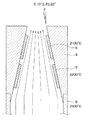
図3は、本実施形態にかかるSiC単結晶製造装置1に備えられる台座部9の近傍の断面図である。この図に示されるように、本実施形態では、第1実施形態に対して、台座部9の内壁面を中心軸方向において伸ばしている。そして、この内壁面に対して周方向に複数の種結晶5を配置しているのに加え、原料ガス3の流動方向にも種結晶5を複数枚(図3中では2枚)並べている。すなわち、原料ガス3の流動方向に沿って多段に配置した種結晶5に対して同時にSiC単結晶を成長させるようにする。
FIG. 3 is a cross-sectional view of the vicinity of the
この場合、例えば、加熱容器8の温度が2400℃程度、台座部9のうち原料ガス3の流動経路上流側に位置する種結晶5と対応する位置が2200℃、流動経路下流側に位置する種結晶5と対応する位置が2100℃となるようにする。
In this case, for example, the temperature of the
このように、原料ガス3の流動方向に沿って種結晶5を多段に配置し、台座部9のうち各段に配置された種結晶5と対応する位置の温度が、原料ガス3の流量経路上流側から下流側に向かって徐々に低下させられるようにすることで、より多数枚の種結晶5に対して同時にSiC単結晶を成長させられる。これにより、よりSiC単結晶の収率を向上させることが可能となる。
In this way, the
(第3実施形態)
本発明の第3実施形態について説明する。本実施形態は、第2実施形態に対して台座部9の構成を変更したものであり、その他に関しては第2実施形態と同様であるため、異なる部分についてのみ説明する。なお、ここでは第2実施形態に対して台座部9を変更する場合について説明するが、第1実施形態についても同様の構成を採用できる。
(Third embodiment)
A third embodiment of the present invention will be described. In the present embodiment, the configuration of the
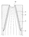
図4は、本実施形態にかかるSiC単結晶製造装置1に備えられる台座部9の近傍の断面図である。この図に示されるように、本実施形態では、台座部9の内壁面に対して種結晶5の周囲を囲む整流板9aを備えるようにしている。整流板9aは、例えば黒鉛や表面をTaC(炭化タンタル)にてコーティングされた黒鉛などで構成され、種結晶5の厚みと同等の高さに設定されている。このような整流板9aを配置すると、整流板9aの表面と種結晶5の表面との高さが同等となっていることから、種結晶5の側壁面によって原料ガス3の乱流が起こることを抑制できる。
FIG. 4 is a cross-sectional view of the vicinity of the
これにより、種結晶5の周囲において原料ガス3を整流でき、よりSiC単結晶を面内において均一に成長させることが可能となる。
As a result, the
(第4実施形態)
本発明の第4実施形態について説明する。本実施形態は、第3実施形態に対して加熱容器8および台座部9の周囲の構成を変更したものであり、その他に関しては第3実施形態と同様であるため、異なる部分についてのみ説明する。なお、ここでは第3実施形態に対して台座部9を変更する場合について説明するが、第1、第2実施形態ついても同様の構成を採用できる。
(Fourth embodiment)
A fourth embodiment of the present invention will be described. In this embodiment, the configuration around the
図5は、本実施形態にかかるSiC単結晶製造装置1に備えられる台座部9の近傍の断面図である。この図に示されるように、本実施形態では、加熱容器8および台座部9の内部にガス流路13を形成し、台座部9における原料ガス3の流動方向下流側に希釈ガスとエッチングガスの少なくとも一方が導入できるようにしている。ガス流路13は、加熱容器8の有底円筒状部材8aと台座部9の外周壁から所定距離内側に形成され、台座部9における原料ガス3の流動方向下流側の端部において、内周壁側に向けて折り曲げられた形状とされている。そして、台座部8の内周壁側にガス出口13aが形成され、このガス出口13aを通じて、台座部9における原料ガス3の流動方向下流側に希釈ガスとエッチングガスの少なくとも一方を導入する。例えば、希釈ガスとしてはArを用いることができ、エッチングガスとしてはHClを用いることができる。これらは、例えばAr:30slm、HCl:5slmの流量で流すことができる。
FIG. 5 is a cross-sectional view of the vicinity of the
このように、ガス流路13を備えて希釈ガスとエッチングガスの少なくとも一方を導入できるようにすると、台座部9における原料ガス3の流動方向下流側での多結晶の付着を防止することが可能となる。すなわち、台座部9における原料ガス3の流動方向下流側では、流路の断面積が小さくなるので、流束が上がり、多結晶が付着して閉塞し易くなる。このため、ガス流路13から希釈ガスとエッチングガスの少なくとも一方が導入されるようにすることで、原料ガス3を希釈したり、多結晶が付着しようとしてもそれをエッチングすることで、多結晶が付着することを抑制することが可能となる。
As described above, when the
(第5実施形態)
本発明の第5実施形態について説明する。本実施形態は、第2実施形態に対して第2断熱材10の構成を変更したものであり、その他に関しては第2実施形態と同様であるため、異なる部分についてのみ説明する。なお、ここでは第2実施形態に対して第2断熱材10を変更する場合について説明するが、第1、第3、第4実施形態ついても同様の構成を採用できる。
(Fifth embodiment)
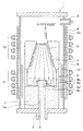
A fifth embodiment of the present invention will be described. In the present embodiment, the configuration of the second
図6は、本実施形態にかかるSiC単結晶製造装置1の断面図である。この図に示されるように、本実施形態では、第1実施形態に対して第2断熱材10の軸方向長を短くし、第2断熱材10が加熱容器8の周囲には配置されるが、台座部9の周囲には配置されないようにしている。このような構成とすれば、台座部9の裏面をより積極的に冷却することが可能となり、台座部9内での温度分布が台座部9の内壁面とより平行となる。これにより、その上に貼り付けられた種結晶5の表面での温度分布をより均一とすることが可能となり、よりSiC単結晶を面内において均一に成長させることが可能となる。
FIG. 6 is a cross-sectional view of the SiC single
(第6実施形態)
本発明の第6実施形態について説明する。本実施形態は、第2実施形態に対してSiC半導体装置1の形状、具体的には真空容器6や台座部9および第2断熱材10の形状を変更したものであり、その他に関しては第2実施形態と同様であるため、異なる部分についてのみ説明する。なお、ここでは第2実施形態に対して第2断熱材10を変更する場合について説明するが、第1、第3〜第5実施形態ついても同様の構成を採用できる。
(Sixth embodiment)
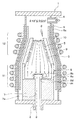
A sixth embodiment of the present invention will be described. In the present embodiment, the shape of the
図7は、本実施形態にかかるSiC単結晶製造装置1の断面図である。この図に示されるように、本実施形態では、台座部9を原料ガス3の流動経路上流側から下流側に向けて内径だけでなく外径も縮小されるような中空円錐台形状としている。そして、この台座部9の周囲に配置される第2断熱材10および真空容器6についても、台座部9と同様に、台座部9を囲んでいる部位において、原料ガス3の流動経路上流側から下流側に向けて内径および外径が縮小させられた中空円錐台経常となるようにしている。
FIG. 7 is a cross-sectional view of the SiC single
このような形状とすると、台座部9の裏面と台座部9の内壁面との距離が短くなる。このため、台座部9の裏面がより冷却し易くなる。特に、台座部9の裏面に対して真空容器6に備えた冷却機構6aを近づけることができるため、台座部9の裏面をより積極的に冷却することが可能となり、台座部9内での温度分布が台座部9の内壁面とより平行となる。これにより、その上に貼り付けられた種結晶5の表面での温度分布をより均一とすることが可能となり、よりSiC単結晶を面内において均一に成長させることが可能となる。
With such a shape, the distance between the back surface of the
なお、ここでは第2断熱材10にて台座部9の周囲が囲まれるようにしたが、第5実施形態のように、台座部9の周囲には第2断熱材10が配置されないようにすれば、より積極的に台座部9の裏面を冷却することが可能となり、さらに上記効果を得ることが可能となる。
Here, the periphery of the
(第7実施形態)
本発明の第7実施形態について説明する。本実施形態は、第1実施形態に対して台座部9の構成を変更したものであり、その他に関しては第1実施形態と同様であるため、異なる部分についてのみ説明する。
(Seventh embodiment)
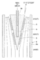
A seventh embodiment of the present invention will be described. In this embodiment, the configuration of the
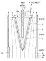
図8は、本実施形態にかかるSiC単結晶製造装置1に備えられる台座部9の近傍の断面図である。この図に示されるように、本実施形態では、台座部9を加熱容器8における原料ガス3の流動経路下流側の中央位置に配置している。台座部9は、外径が原料ガス3の流動経路下流側に向かって徐々に拡大された円錐形状とされ、台座部9の厚みは、原料ガス3の流動経路下流側に向かって徐々に厚くなっている。このため、原料ガス3の流動経路の断面積が徐々に縮小され、台座部9の外壁面によって原料ガス3の流束が徐々に絞られる。また、台座部9の外壁面は基本的には円錐形状とされているが、種結晶5が配置される位置において部分的に平坦面とされ、これが種結晶5の貼付面とされる。この平坦面は、台座部9の外壁面の複数箇所に備えられ、周方向において等間隔に並べられていると共に、中心軸方向にも複数段並べられている。
FIG. 8 is a cross-sectional view of the vicinity of the
このように、台座部9の外壁面のうちの平坦面に種結晶5が貼り付けられることで、種結晶5が加熱容器8の中心軸に対して傾斜した状態で配置される。台座部9の内壁面が加熱容器8の中心軸に対して成す角度θは、原料ガス3の流量に応じて適宜設定される。例えば、原料ガス3としてSiH4、C3H8、H2を用い、これらの流量をSiH4:1slm、C3H8:333sccm、H2:10〜15slmとする場合には、角度θが13°≦θ≦23°に設定されると好ましい。
In this way, the
また、台座部9の中心位置には、種結晶5の裏面側から台座部9を冷却することが可能な冷却機構9bが備えられている。このため、より台座部9を種結晶5の裏面側から効率よく冷却できる構造と可能とされている。
A
このような構成のSiC半導体装置1を用いて、種結晶5の表面にSiC単結晶を成長させる場合、例えば、加熱容器8の温度が2400℃程度、台座部9の温度が2200℃程度となるように第1、第2加熱装置11、12を制御する。
When a SiC single crystal is grown on the surface of the
このとき、台座部9の外壁面を加熱容器8の中心軸に対して傾斜させていることから、種結晶5の表面での温度分布がほぼ均一となる。すなわち、台座部9のうち種結晶5の裏面側からの冷却と、第1加熱装置11によって加熱された加熱容器8からの輻射熱効果により、台座部9内での温度分布が台座部9の内壁面とほぼ平行となり、その上に貼り付けられた種結晶5の表面での温度分布もほぼ均一となる。このため、SiC単結晶製造装置1の中心軸と垂直な方向に等温分布が形成されるような従来の場合と比較して、本実施形態のSiC単結晶製造装置1では、種結晶5の表面での温度分布、引いてはその上に成長させられるSiC単結晶の成長表面の温度分布が均一となる。したがって、SiC単結晶を面内において均一に成長させることが可能となる。これにより、第1実施形態と同様の効果を得ることが可能となる。
At this time, since the outer wall surface of the
(第8実施形態)
本発明の第8実施形態について説明する。本実施形態は、第7実施形態に対して台座部9の構成を変更したものであり、その他に関しては第7実施形態と同様であるため、異なる部分についてのみ説明する。
(Eighth embodiment)
An eighth embodiment of the present invention will be described. In the present embodiment, the configuration of the
図9は、本実施形態にかかるSiC単結晶製造装置1に備えられる台座部9の近傍の断面図である。この図に示されるように、本実施形態では、第7実施形態に対して、台座部9の外壁面を中心軸方向において伸ばしている。そして、この外壁面に対して周方向に複数の種結晶5を配置しているのに加え、中心軸方向にも種結晶5を複数枚(図9中では2枚)並べている。すなわち、原料ガス3の流動方向に沿って多段に配置した種結晶5に対して同時にSiC単結晶を成長させるようにする。
FIG. 9 is a cross-sectional view of the vicinity of the
この場合、例えば、加熱容器8の温度が2400℃程度、台座部9のうち原料ガス3の流動経路上流側に位置する種結晶5と対応する位置が2200℃、流動経路下流側に位置する種結晶5と対応する位置が2100℃となるようにする。
In this case, for example, the temperature of the
このように、原料ガス3の流動方向に沿って種結晶5を多段に配置し、台座部9のうち各段に配置された種結晶5と対応する位置の温度が、原料ガス3の流量経路上流側から下流側に向かって徐々に低下させられるようにすることで、より多数枚の種結晶5に対して同時にSiC単結晶を成長させられる。これにより、よりSiC単結晶の収率を向上させることが可能となる。
In this way, the
(第9実施形態)
本発明の第9実施形態について説明する。本実施形態は、第8実施形態に対して台座部9の構成を変更したものであり、その他に関しては第8実施形態と同様であるため、異なる部分についてのみ説明する。なお、ここでは第8実施形態に対して台座部9を変更する場合について説明するが、第7実施形態についても同様の構成を採用できる。
(Ninth embodiment)
A ninth embodiment of the present invention will be described. In the present embodiment, the configuration of the
図10は、本実施形態にかかるSiC単結晶製造装置1に備えられる台座部9の近傍の断面図である。この図に示されるように、本実施形態では、台座部9の外壁面に対して種結晶5の周囲を囲む整流板9aを備えるようにしている。整流板9aは、例えば黒鉛や表面をTaC(炭化タンタル)にてコーティングされた黒鉛などで構成され、種結晶5の厚みと同等の高さに設定されている。このような整流板9aを配置すると、整流板9aの表面と種結晶5の表面との高さが同等となっていることから、種結晶5の側壁面によって原料ガス3の乱流が起こることを抑制できる。
FIG. 10 is a cross-sectional view of the vicinity of the
これにより、種結晶5の周囲において原料ガス3を整流でき、よりSiC単結晶を面内において均一に成長させることが可能となる。
As a result, the
(第10実施形態)
本発明の第10実施形態について説明する。本実施形態は、第9実施形態に対して加熱容器8および台座部9の周囲の構成を変更したものであり、その他に関しては第9実施形態と同様であるため、異なる部分についてのみ説明する。なお、ここでは第9実施形態に対して台座部9を変更する場合について説明するが、第7、第8実施形態ついても同様の構成を採用できる。
(10th Embodiment)
A tenth embodiment of the present invention will be described. In the present embodiment, the configuration around the
図11は、本実施形態にかかるSiC単結晶製造装置1に備えられる台座部9の近傍の断面図である。この図に示されるように、本実施形態では、ガス流路13を備えることで、台座部9の周囲および台座部9における原料ガス3の流動方向下流側において希釈ガスとエッチングガスの少なくとも一方が導入できるようにしている。
FIG. 11 is a cross-sectional view of the vicinity of the
具体的には、ガス流路13として、第1ガス流路13bと第2ガス流路13cが形成されている。第1ガス流路13bは、加熱容器8における有底円筒状部材8の円筒状部分に設けられている。そして、有底円筒状部材8は、第1ガス流路13bの内側と比較して外側において、円筒状部分の軸方向長が長くされている。これにより、第1ガス流路13bから台座部8の周囲において希釈ガスとエッチングガスの少なくとも一方が導入できるようにしている。また、第2ガス流路13cは、台座部9の後端から径方向外側に向かって延設されている。この第2ガス流路13cを通じて、台座部9における原料ガス3の流動方向下流側において希釈ガスとエッチングガスの少なくとも一方が導入できるようにしている。例えば、希釈ガスとしてはArを用いることができ、エッチングガスとしてはHClを用いることができる。これらは、例えばAr:30slm、HCl:5slmの流量で流すことができる。
Specifically, a
このように、ガス流路13から希釈ガスとエッチングガスの少なくとも一方を導入できるようにすると、台座部9の周囲および台座部9における原料ガス3の流動方向下流側での多結晶の付着を防止することが可能となる。すなわち、台座部9の周囲および台座部9における原料ガス3の流動方向下流側では、原料ガス3の流路の断面積が縮小されるため流束が上がり、多結晶が付着して閉塞し易くなる。このため、ガス流路13から希釈ガスとエッチングガスの少なくとも一方が導入されるようにすることで、原料ガス3を希釈したり、多結晶が付着しようとしてもそれをエッチングすることで、多結晶が付着することを抑制することが可能となる。
As described above, when at least one of the dilution gas and the etching gas can be introduced from the
(他の実施形態)
上記各実施形態に示したSiC単結晶製造装置1の具体的な構造は、単なる一例であり、形状や材質などについて適宜変更することができる。
(Other embodiments)
The specific structure of the SiC single
例えば、種結晶5や台座部9における種結晶5の貼付面が円形状である場合について説明したが、これらは必ずしも円形状である必要はなく、正方形などの他の形状であっても構わない。また、上記各実施形態では、加熱容器8のうち中空円筒状部材を構成するものとして有底円筒状部材8aを用いたが、底部を有しない単なる中空円筒状部材としても良い。
For example, although the case where the
また、上記各実施形態すべてについて、誘導加熱方式と直接加熱方式の双方に対して本発明が適用できる。 Further, the present invention can be applied to both the induction heating method and the direct heating method for all the above embodiments.
1 SiC単結晶製造装置
3 原料ガス
5 種結晶
6 真空容器
6a 冷却機構
8 加熱容器
8a 有底円筒状部材
8b 邪魔板
9 台座部
9a 整流板
9b 冷却機構
10 第2断熱材
11 第1加熱装置
12 第2加熱装置
DESCRIPTION OF
Claims (8)
前記原料ガス(3)の導入導出が行え、内部空間の圧力を真空引きすることにより減圧できる構造とされた真空容器(6)と、
中空円筒状部材(8a)を有して構成され、前記真空容器(6)内に配置され、前記原料ガス(3)の加熱を行う加熱容器(8)と、
前記真空容器(6)内において、前記加熱容器(8)よりも前記原料ガス(3)の流動経路下流側に配置され、前記種結晶(5)が貼り付けられる台座部(9)とを有し、
前記真空容器(6)には、前記台座部(9)の周囲を囲む位置に、前記台座部(9)の外壁面を冷却する冷却機構(6a)が備えられ、
前記台座部(9)は、前記加熱容器(8)における前記中空円筒状部材(8a)のうちの前記原料ガス(3)の流動経路下流側の端部に配置され、該中空円筒状部材(8a)の中心軸に対して内壁面が傾斜するように該台座部(9)の内径が前記原料ガス(3)の流動経路下流側に向けて縮小させられ、前記内壁面に前記種結晶(5)が貼り付けられる面が複数備えられていることを特徴とする炭化珪素単結晶の製造装置。 A silicon carbide source gas (3) is supplied from below to a seed crystal (5) formed on a silicon carbide single crystal substrate to supply the seed crystal (5) located above, In the silicon carbide single crystal manufacturing apparatus for growing a silicon carbide single crystal on the surface of the crystal (5),
A vacuum vessel (6) having a structure capable of introducing and derivation of the source gas (3) and depressurizing the internal space by evacuating;
A heating container (8) configured to have a hollow cylindrical member (8a), disposed in the vacuum container (6), and for heating the source gas (3);
In the vacuum vessel (6), there is a pedestal (9) that is arranged on the downstream side of the flow path of the source gas (3) relative to the heating vessel (8) and to which the seed crystal (5) is attached. And
The vacuum vessel (6) is provided with a cooling mechanism (6a) for cooling the outer wall surface of the pedestal portion (9) at a position surrounding the pedestal portion (9).
The pedestal (9) is disposed at the downstream end of the flow path of the source gas (3) in the hollow cylindrical member (8a) in the heating vessel (8), and the hollow cylindrical member ( The inner diameter of the pedestal portion (9) is reduced toward the downstream side of the flow path of the source gas (3) so that the inner wall surface is inclined with respect to the central axis of 8a), and the seed crystal ( An apparatus for producing a silicon carbide single crystal, comprising a plurality of surfaces to which 5) is attached.
前記原料ガス(3)の導入導出が行え、内部空間の圧力を真空引きすることにより減圧できる構造とされた真空容器(6)と、
中空円筒状部材(8a)を有して構成され、前記真空容器(6)内に配置され、前記原料ガス(3)の加熱を行う加熱容器(8)と、
前記加熱容器(8)における前記原料ガス(3)の流動経路下流側に配置され、該流動経路下流側に向かって徐々に外径が拡大された円錐形状で、外壁面に前記種結晶(5)が貼り付けられる台座部(9)とを有し、
前記台座部(9)には、前記種結晶(5)の裏面側から前記台座部(9)を冷却する冷却機構(9b)が備えられ、
前記台座部(9)の前記外壁面には、前記種結晶(5)が貼り付けられる面が複数備えられていることを特徴とする炭化珪素単結晶の製造装置。 A silicon carbide source gas (3) is supplied from below to a seed crystal (5) formed on a silicon carbide single crystal substrate to supply the seed crystal (5) located above, In the silicon carbide single crystal manufacturing apparatus for growing a silicon carbide single crystal on the surface of the crystal (5),
A vacuum vessel (6) having a structure capable of introducing and derivation of the source gas (3) and depressurizing the internal space by evacuating;
A heating container (8) configured to have a hollow cylindrical member (8a), disposed in the vacuum container (6), and for heating the source gas (3);
It is arranged on the downstream side of the flow path of the source gas (3) in the heating container (8), has a conical shape with the outer diameter gradually enlarged toward the downstream side of the flow path, and the seed crystal (5 ) To which the pedestal (9) is attached,
The pedestal portion (9) is provided with a cooling mechanism (9b) for cooling the pedestal portion (9) from the back side of the seed crystal (5),
An apparatus for producing a silicon carbide single crystal, wherein the outer wall surface of the pedestal portion (9) is provided with a plurality of surfaces to which the seed crystal (5) is attached.
前記台座部(9)には、該台座部(9)における前記原料ガス(3)の流動方向下流側に希釈ガスとエッチングガスの少なくとも一方を導入する第2ガス流路(13c)が備えられていることを特徴とする請求項5ないし7のいずれか1つに記載の炭化珪素単結晶の製造装置。 The heating vessel (8) includes a first gas flow path (13b) for introducing at least one of a dilution gas and an etching gas around the pedestal portion (9),
The pedestal portion (9) is provided with a second gas flow path (13c) for introducing at least one of a dilution gas and an etching gas downstream of the pedestal portion (9) in the flow direction of the source gas (3). 8. The apparatus for producing a silicon carbide single crystal according to claim 5, wherein the silicon carbide single crystal production apparatus is provided.
Priority Applications (1)
| Application Number | Priority Date | Filing Date | Title |
|---|---|---|---|
| JP2011002292A JP5482669B2 (en) | 2011-01-07 | 2011-01-07 | Silicon carbide single crystal manufacturing equipment |
Applications Claiming Priority (1)
| Application Number | Priority Date | Filing Date | Title |
|---|---|---|---|
| JP2011002292A JP5482669B2 (en) | 2011-01-07 | 2011-01-07 | Silicon carbide single crystal manufacturing equipment |
Publications (2)
| Publication Number | Publication Date |
|---|---|
| JP2012144386A true JP2012144386A (en) | 2012-08-02 |
| JP5482669B2 JP5482669B2 (en) | 2014-05-07 |
Family
ID=46788376
Family Applications (1)
| Application Number | Title | Priority Date | Filing Date |
|---|---|---|---|
| JP2011002292A Active JP5482669B2 (en) | 2011-01-07 | 2011-01-07 | Silicon carbide single crystal manufacturing equipment |
Country Status (1)
| Country | Link |
|---|---|
| JP (1) | JP5482669B2 (en) |
Cited By (1)
| Publication number | Priority date | Publication date | Assignee | Title |
|---|---|---|---|---|
| CN102713167A (en) * | 2010-01-21 | 2012-10-03 | 三菱重工业株式会社 | Waste heat recovery power generation device and ship with same |
Citations (5)
| Publication number | Priority date | Publication date | Assignee | Title |
|---|---|---|---|---|
| JPS6425541A (en) * | 1987-07-22 | 1989-01-27 | Daiwa Handotai Sochi Kk | Vertical cvd reaction apparatus |
| JPS6436085A (en) * | 1987-07-31 | 1989-02-07 | Canon Kk | Method and apparatus for forming functional deposition film by microwave plasma cvd method |
| JPH03194920A (en) * | 1989-12-22 | 1991-08-26 | Fuji Electric Co Ltd | Device for epitaxial growth |
| JP2006086230A (en) * | 2004-09-14 | 2006-03-30 | Hitachi Kokusai Electric Inc | Semiconductor manufacturing device |
| JP2006111510A (en) * | 2004-10-18 | 2006-04-27 | Denso Corp | Method for producing silicon carbide single crystal |
-
2011
- 2011-01-07 JP JP2011002292A patent/JP5482669B2/en active Active
Patent Citations (5)
| Publication number | Priority date | Publication date | Assignee | Title |
|---|---|---|---|---|
| JPS6425541A (en) * | 1987-07-22 | 1989-01-27 | Daiwa Handotai Sochi Kk | Vertical cvd reaction apparatus |
| JPS6436085A (en) * | 1987-07-31 | 1989-02-07 | Canon Kk | Method and apparatus for forming functional deposition film by microwave plasma cvd method |
| JPH03194920A (en) * | 1989-12-22 | 1991-08-26 | Fuji Electric Co Ltd | Device for epitaxial growth |
| JP2006086230A (en) * | 2004-09-14 | 2006-03-30 | Hitachi Kokusai Electric Inc | Semiconductor manufacturing device |
| JP2006111510A (en) * | 2004-10-18 | 2006-04-27 | Denso Corp | Method for producing silicon carbide single crystal |
Cited By (1)
| Publication number | Priority date | Publication date | Assignee | Title |
|---|---|---|---|---|
| CN102713167A (en) * | 2010-01-21 | 2012-10-03 | 三菱重工业株式会社 | Waste heat recovery power generation device and ship with same |
Also Published As
| Publication number | Publication date |
|---|---|
| JP5482669B2 (en) | 2014-05-07 |
Similar Documents
| Publication | Publication Date | Title |
|---|---|---|
| JP4992965B2 (en) | Silicon carbide single crystal manufacturing equipment | |
| KR101447476B1 (en) | Apparatus for manufacturing silicon carbide single crystal | |
| JP5500953B2 (en) | Film forming apparatus and film forming method | |
| JP2010232624A (en) | Vapor phase growth apparatus for group-iii nitride semiconductor | |
| WO2013014920A1 (en) | Silicon carbide single crystal manufacturing device | |
| JP4924105B2 (en) | Silicon carbide single crystal manufacturing apparatus and manufacturing method | |
| US9328431B2 (en) | Apparatus for manufacturing a silicon carbide single crystal comprising a mounting portion and a purge gas introduction system | |
| JP2016162921A (en) | Sic chemical vapor deposition device | |
| JP2008230924A (en) | Apparatus and method for producing silicon carbide single crystal | |
| JP5482669B2 (en) | Silicon carbide single crystal manufacturing equipment | |
| JP2016050164A (en) | SiC chemical vapor deposition apparatus | |
| JP5831339B2 (en) | Method for producing silicon carbide single crystal | |
| JP5648604B2 (en) | Silicon carbide single crystal manufacturing equipment | |
| JP5811012B2 (en) | Silicon carbide single crystal manufacturing apparatus and manufacturing method | |
| JP6052051B2 (en) | Silicon carbide single crystal manufacturing equipment | |
| JP6187372B2 (en) | Silicon carbide single crystal manufacturing equipment | |
| JP6413925B2 (en) | Silicon carbide single crystal manufacturing equipment | |
| JP4941475B2 (en) | Manufacturing method of silicon carbide single crystal and manufacturing apparatus suitable therefor | |
| US20210040645A1 (en) | Silicon carbide single crystal manufacturing apparatus, and manufacturing method of silicon carbide single crystal | |
| JP2011132083A (en) | Apparatus for producing silicon carbide single crystal and method for producing silicon carbide single crystal using the same | |
| JP7024622B2 (en) | Silicon carbide single crystal and its manufacturing method | |
| JP5578146B2 (en) | Silicon carbide single crystal manufacturing equipment | |
| JP5842725B2 (en) | Silicon carbide single crystal manufacturing equipment | |
| JP2012067012A (en) | Method of producing silicon carbide single crystal | |
| JP5867335B2 (en) | Silicon carbide single crystal manufacturing apparatus and manufacturing method |
Legal Events
| Date | Code | Title | Description |
|---|---|---|---|
| A621 | Written request for application examination |
Free format text: JAPANESE INTERMEDIATE CODE: A621 Effective date: 20130215 |
|
| A977 | Report on retrieval |
Free format text: JAPANESE INTERMEDIATE CODE: A971007 Effective date: 20130919 |
|
| A131 | Notification of reasons for refusal |
Free format text: JAPANESE INTERMEDIATE CODE: A131 Effective date: 20131029 |
|
| A521 | Request for written amendment filed |
Free format text: JAPANESE INTERMEDIATE CODE: A523 Effective date: 20131224 |
|
| TRDD | Decision of grant or rejection written | ||
| A01 | Written decision to grant a patent or to grant a registration (utility model) |
Free format text: JAPANESE INTERMEDIATE CODE: A01 Effective date: 20140121 |
|
| A61 | First payment of annual fees (during grant procedure) |
Free format text: JAPANESE INTERMEDIATE CODE: A61 Effective date: 20140203 |
|
| R151 | Written notification of patent or utility model registration |
Ref document number: 5482669 Country of ref document: JP Free format text: JAPANESE INTERMEDIATE CODE: R151 |
|
| R250 | Receipt of annual fees |
Free format text: JAPANESE INTERMEDIATE CODE: R250 |
|
| R250 | Receipt of annual fees |
Free format text: JAPANESE INTERMEDIATE CODE: R250 |
|
| R250 | Receipt of annual fees |
Free format text: JAPANESE INTERMEDIATE CODE: R250 |
|
| R250 | Receipt of annual fees |
Free format text: JAPANESE INTERMEDIATE CODE: R250 |
|
| R250 | Receipt of annual fees |
Free format text: JAPANESE INTERMEDIATE CODE: R250 |
|
| R250 | Receipt of annual fees |
Free format text: JAPANESE INTERMEDIATE CODE: R250 |
|
| R250 | Receipt of annual fees |
Free format text: JAPANESE INTERMEDIATE CODE: R250 |
|
| R250 | Receipt of annual fees |
Free format text: JAPANESE INTERMEDIATE CODE: R250 |