JP2012144352A - Part feeder - Google Patents
Part feeder Download PDFInfo
- Publication number
- JP2012144352A JP2012144352A JP2011004974A JP2011004974A JP2012144352A JP 2012144352 A JP2012144352 A JP 2012144352A JP 2011004974 A JP2011004974 A JP 2011004974A JP 2011004974 A JP2011004974 A JP 2011004974A JP 2012144352 A JP2012144352 A JP 2012144352A
- Authority
- JP
- Japan
- Prior art keywords
- component
- screw
- head
- supply device
- take
- Prior art date
- Legal status (The legal status is an assumption and is not a legal conclusion. Google has not performed a legal analysis and makes no representation as to the accuracy of the status listed.)
- Granted
Links
Images
Landscapes
- Discharge Of Articles From Conveyors (AREA)
- Feeding Of Articles To Conveyors (AREA)
Abstract
【課題】ネジを垂直位置から傾いた状態で取り出せるようにするネジ供給装置。
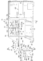
【解決手段】この装置は、軸部(S1)と頭部(S2)とを有する複数のネジ(S)を頭部を上にして一列にならべるネジ整列部(21)と、最前位置のネジを外部から取り出し可能とするネジ取出し部(16)とを備える。ネジ取出し部(16)は、最前位置のネジが、該一列に並べられたネジから離れて下方に動いて、その頭部(S2)が前方に向く配向とする配向変換部(14h)と、頭部(S2)が前方に向く配向とされたネジ(S)を受け入れ、当該ネジ供給装置の外部からの該頭部に対するアクセスが可能であるように支持するネジ支持部(24)と、該ネジ支持部(24)に支持されたネジ(S)を、該ネジの長手方向軸線に対して側方に動かして当該ネジ供給装置(10)の外部に取り出すのを可能とするネジ取出し通路(25a.25b)とを有する。
【選択図】図1A screw supply device that enables a screw to be taken out from a vertical position.
The device includes a screw aligning portion (21) in which a plurality of screws (S) having a shaft portion (S1) and a head portion (S2) are arranged in a row with the head portion facing up, and a screw at the foremost position. And a screw take-out portion (16) that can be taken out from the outside. The screw take-out portion (16) includes an orientation changing portion (14h) in which the foremost screw moves downward away from the aligned screws so that the head (S2) is oriented forward. A screw support (24) for receiving a screw (S) oriented with the head (S2) facing forward and supporting the head from outside the screw supply device; A screw extraction passage (which allows the screw (S) supported by the screw support portion (24) to move laterally with respect to the longitudinal axis of the screw and to be taken out of the screw supply device (10). 25a.25b).
[Selection] Figure 1
Description
本発明は、ネジ、リベット、釘などの頭部及び軸部からなる部品の供給装置に関する。 The present invention relates to a component supply device including a head portion and a shaft portion such as screws, rivets, and nails.
例えば、この種の部品供給装置としては、ネジ締め作業において使用するネジを、ネジの頭部を上にした状態で一列に並べ供給し、その最前位置にあるネジから順に取り出すことができるようにするネジ供給装置が知られている。従来、この種のネジ供給装置としては、多数のネジを受け入れるネジ収容室と、ネジの頭部を上した状態で一列に支持しながら該ネジを取出し位置まで案内する案内溝を有する細長いガイド部材と、該ガイド部材を横断するように揺動して該ガイド部材に適正に支持されていないネジを掃い退けるためのブラシを備えているものがある(特許文献1、特許文献2)。
For example, in this type of component supply device, the screws used in the screw tightening operation can be supplied in a row with the screw heads facing up, and can be sequentially removed from the screw at the foremost position. A screw supply device is known. Conventionally, as this type of screw supply device, an elongated guide member having a screw receiving chamber for receiving a large number of screws, and a guide groove for guiding the screws to a take-out position while supporting them in a row with the heads of the screws raised. And a brush for sweeping away a screw that is not properly supported by the guide member by swinging across the guide member (
上述のネジ供給装置においては、一列に並べられたネジは、ネジの頭部を上にして略垂直とされ、ガイド部材にかけられる振動によって該ガイド部材に沿って前進させられ、ネジ取出し位置まできたネジは、該ネジの上方からアクセスしたスクリュードライバの磁化された先端によって頭部を保持され、上方に持ち上げられるようにして取り出される。 In the above-described screw supply device, the screws arranged in a line are made substantially vertical with the screw heads facing up, and are advanced along the guide member by vibration applied to the guide member, and reach the screw extraction position. The screw is removed so that the head is held by the magnetized tip of the screwdriver accessed from above the screw and lifted upward.
従って、取り出されたネジ及びそれを保持するスクリュードライバは略垂直の向きとなっており、これをその向きのままにして所要位置においてねじ回し締付作業を行う場合には、円滑な作業が可能である。しかしながら、ネジは必ずしも垂直な状態で取り付けられるとは限らず、例えば、略水平にした状態で行われる場合もある。 Therefore, the removed screw and the screwdriver that holds it are in a substantially vertical orientation, and when this is left in that orientation and the screwdriver is tightened at the required position, smooth operation is possible. It is. However, the screw is not necessarily attached in a vertical state, and may be performed in a substantially horizontal state, for example.
このようなネジの取付作業にあっては、一旦、垂直に取り出したネジ及びそれを保持するスクリュードライバの向きを、水平に変える必要があり、作業効率が悪い。 In such screw mounting work, it is necessary to change the direction of the screw taken out vertically and the screw driver holding the screw to the horizontal, and the work efficiency is poor.
本発明は、このような点に鑑み、典型的な例としては、ネジ供給装置からネジを取り出したときに、その向きを余り変えることが無く、当該ネジの取り付けができるようにしたネジ供給装置を提供しようとするものである。上記においてはネジを例に挙げて、従来技術の問題を説明したが、リベットや釘などにおいても同様の問題が生じ得るものであり、従って、本発明は、頭部及び軸部からなる部品供給において、頭部が所要の角度を向いて供給されるようにする装置を提供するものである。 In view of such a point, the present invention provides a typical example of a screw supply device in which when the screw is taken out from the screw supply device, the direction of the screw is not changed so much that the screw can be attached. Is to provide. In the above, the problem of the prior art has been described by taking the screw as an example, but the same problem may occur in rivets, nails, etc. Therefore, the present invention provides a component supply comprising a head and a shaft. In the above, an apparatus is provided in which the head is supplied at a required angle.
すなわち、本発明は、
軸部(以下に述べる実施形態の説明におけるネジSの軸部S1)と該軸部の一端に設けられた頭部(ネジSの頭部S2)とからなる部品を供給するための部品供給装置(ネジ供給装置10)であって、複数の上記部品(S)を受け入れ、該部品の頭部(S2)を上にして一方向に整列して前進させる部品整列部(21)と、該部品整列部により一方向に整列された部品の最前位置の部品を当該部品供給装置(10)の外部から取り出し可能とする部品取出し部(16)と、を備え、該部品取出し部(16)は、該最前位置の部品を、該部品整列部により一方向に整列された他の部品から離れて下方に動かし、部品(S)の頭部(S2)を該部品整列部により一方向に整列された前記部品の前進する向きに向かせる配向変換部(14h)と、該配向変換部により該部品(S)の頭部(S2)が該部品整列部により一方向に整列された前記部品の前進する向きに向いた前記部品(S)を受け入れ、当該部品供給装置の外部からの該部品の頭部(S2)に対するアクセスが可能であるように支持する部品支持部材(24)と、を有し、該支持部材によって支持された部品の頭部を保持して当該部品供給装置の外部に取り出せるようにした部品供給装置を提供する。
That is, the present invention
Component supply device for supplying a component including a shaft portion (shaft portion S1 of screw S in the description of the embodiment described below) and a head portion (head portion S2 of screw S) provided at one end of the shaft portion (Screw supply device 10), which receives a plurality of the components (S), aligns them in one direction with the heads (S2) of the components facing up, and advances the components. A component unloading section (16) that allows the component at the foremost position of the components aligned in one direction by the aligning section to be unloaded from the outside of the component supply device (10), and the component unloading section (16) The frontmost part is moved downward away from the other parts aligned in one direction by the part aligning unit, and the head (S2) of the part (S) is aligned in one direction by the part aligning unit. An orientation changing portion (14h) for directing the component in a forward direction; The head (S2) of the component (S) is received in the direction conversion unit by receiving the component (S) oriented in the forward direction of the component aligned in one direction by the component alignment unit, and is external to the component supply device. A component support member (24) that supports the component head from the component (S2) so that the component head can be accessed, and holds the component head supported by the support member to supply the component Provided is a component supply apparatus which can be taken out of the apparatus.
具体的には、該部品支持部材(24)に支持された部品(S)を、該部品の長手方向軸線(該部品整列部により一方向に整列された前記部品の前進する方向)に対して側方(直角の方向)に動かして当該部品供給装置(10)の外部に取り出すのを可能とする部品取り出し通路(25a.25b)を有するようにしたり、該部品支持部材に支持された部品を、その長手方向軸線に沿って前方に引き出すことにより、当該部品供給装置の外部に取り出すようにしたりすることができる。 Specifically, the component (S) supported by the component support member (24) is moved with respect to the longitudinal axis of the component (the advancing direction of the component aligned in one direction by the component aligning portion). It has a part take-out passage (25a.25b) that can be moved to the side (perpendicular direction) and can be taken out of the part supply device (10), or a part supported by the part support member By pulling it forward along its longitudinal axis, it can be taken out of the component supply device.
さらに具体的には、該部品支持部材が、部品を、略水平に支持したり、部品の頭部を前方斜め上向きにするように支持したり、前方斜め下向きにするように支持したりするようにすることができる。 More specifically, the component support member supports the component substantially horizontally, supports the head of the component so that the head of the component is obliquely upward, and supports the component so that the head of the component is obliquely downward. Can be.
この部品供給装置は、前述の従来の部品供給装置のように部品をスクリュードライバなどの部品取り出し工具によって垂直に持ち上げるのではなく、部品の頭部を前方に向くようにしておいて取り出すようにするものである。このため、部品を垂直ではない状態で締め付ける場合にも、取り出した部品の向きを大きく変える必要が無く、部品取り出し工具からの部品の落下が生じにくく、効率の良い作業を可能とする。特に、部品を、該部品の長手方向軸線に対して側方に動かして外部に取り出すようにした場合、その側方の位置に部品取付場所があるようにすれば、部品取り出し工具を部品供給装置から側方に動かすだけで部品取付場所に位置させることができ、作業効率を大幅に向上することが可能である。尚、側方とは、長手方向軸線に直交する方向成分をもつ方向を意味し、左方や右方に限定されるものではない。 This component supply device does not lift the component vertically with a component extraction tool such as a screwdriver as in the conventional component supply device described above, but takes out the component with its head facing forward. Is. For this reason, even when the components are tightened in a non-vertical state, it is not necessary to greatly change the orientation of the removed components, and it is difficult for the components to fall from the component extraction tool, thus enabling efficient work. In particular, when a part is moved laterally with respect to the longitudinal axis of the part and taken out to the outside, the part feeding tool can be used as a part feeding device if there is a part mounting place at the side position. It can be positioned at the part mounting location by simply moving it side to side, and the work efficiency can be greatly improved. Note that the side means a direction having a direction component orthogonal to the longitudinal axis, and is not limited to the left or right.
より具体的には、部品支持部材(24)が、該部品支持部材に受け入れられた部品(S)の軸部(S1)を支持する部品支持面(24a)を有し、該部品取出し部(16)が更に、該配向変換部(14h)を通して該部品取出し部(16)に送られてくる部品の頭部(S2)とその両側から係合することにより、該部品が該部品支持面(24a)の所定の位置に保持されるようにする部品保持部材(28)であって、該部品の頭部(S2)に対する前方からのアクセスを可能なように該部品の頭部の前面(S3)を露呈しながら該部品の頭部(S2)の両側に係合して該頭部を保持すると共に、該部品(S)を部品支持部材(24)から該側方に動かして取り出すときに、該部品の頭部(S2)の動きに伴って、該部品の頭部から外れるように変位可能とされた部品保持部材(28)を有するようにすることができる。 More specifically, the component support member (24) has a component support surface (24a) for supporting the shaft portion (S1) of the component (S) received by the component support member, and the component take-out portion ( 16) further engages from both sides with the head portion (S2) of the component sent to the component take-out portion (16) through the orientation changing portion (14h), so that the component becomes the component support surface ( 24a) a component holding member (28) to be held at a predetermined position, and the front surface (S3) of the component head so that the component head (S2) can be accessed from the front. ) Is engaged with both sides of the head (S2) of the component to hold the head, and the component (S) is moved from the component support member (24) to the side to be taken out. , So as to move away from the head of the part with the movement of the head of the part (S2) It is possible to have a component holding member (28) that can be displaced.
部品保持部材は、部品の頭部の位置決め及び保持を行うものである。 The component holding member is for positioning and holding the head of the component.
部品保持部材(28)は、具体的には、該配向変換部(14h)を通して該部品取出し部(16)に送られてくる部品の頭部(S2)とその左及び右の両側から係合することにより、該部品が該部品支持面の所定の位置に保持されるようにする左側及び右側部品保持部材(28a,28b)を有し、該部品取り出し通路(25a、25b)が、該部品支持面(24a)の左側及び右側の両側に設けられており、該左側及び右側部品保持部材が、それぞれ、該左側及び右側の部品取り出し通路(25a、25b)を通される部品の頭部(S2)の動きに伴って、該部品の頭部から外れるように変位可能とされるようにすることができる。 Specifically, the component holding member (28) is engaged from both the left and right sides of the component head (S2) sent to the component take-out portion (16) through the orientation changing portion (14h). The left and right component holding members (28a, 28b) are provided so that the component is held at a predetermined position on the component support surface, and the component take-out passages (25a, 25b) Provided on both the left and right sides of the support surface (24a), the left and right component holding members are the heads of the components (25a, 25b) that pass through the left and right component take-out passages (25a, 25b), respectively. Along with the movement of S2), the part can be displaced so as to be detached from the head of the part.
すなわち、部品取り出し通路は、部品支持面の一側だけに設けても良いが、両側に設ければ、より作業効率を上げることが可能となる。 In other words, the component take-out passage may be provided only on one side of the component support surface, but if it is provided on both sides, the work efficiency can be further improved.
また、部品整列部(21)から部品取り出し部(16)に延び、部品の頭部(S2)を上にして一列にならべられた複数の部品の軸部(S1)を受け入れる細長い溝(14a)、及び、溝の両側に沿って相互に並行に延び該一列に並べられた部品の頭部(S2)の下面の該軸部(S1)の両側の部分を摺動可能に支持する上面(14c)を有するガイド部材(14)であって、該ガイド部材(14)の上面の前端部分(14d)が前方に向かうに従い下方に向かうように湾曲して終端し、該一列に並べられた部品の最前位置の部品が、該湾曲した前端部分(14d)に沿ってガイドされることにより、その頭部が前向きとなって該部品支持部材(24)に供給されるようにされ、該湾曲された該前端部分(14d)が、該配向変換部(14h)を形成するようにすることができる。 Also, an elongated groove (14a) that extends from the component aligning portion (21) to the component picking portion (16) and receives the shaft portions (S1) of a plurality of components arranged in a row with the heads (S2) of the components facing up. And an upper surface (14c) that slidably supports portions on both sides of the shaft portion (S1) of the lower surface of the heads (S2) of the parts that extend in parallel with each other along both sides of the groove and are arranged in a row. ), And the front end portion (14d) of the upper surface of the guide member (14) is curved to end downward as it goes forward, and ends in a line. The foremost part is guided along the curved front end portion (14d) such that its head is directed forward and supplied to the part support member (24), and the curved part is The front end portion (14d) is connected to the orientation changing portion (14h). Can be formed.
該配向変換部は、より具体的には、該ガイド部材(14)の上面(14c)の湾曲された前端部分(14d)から前方に間隔をあけて設けられたガイドカバー(26)であって、該湾曲された前端部分(14d)に沿ってガイドされる部品(S)の頭部(S2)が該ガイドカバー(26)と摺動することにより、該頭部(S2)の前向きの傾きが確定されるようにするガイドカバー(26)を有するようにすることができる。 More specifically, the orientation changing portion is a guide cover (26) provided at a front interval from the curved front end portion (14d) of the upper surface (14c) of the guide member (14). The head (S2) of the component (S) guided along the curved front end portion (14d) slides with the guide cover (26), so that the head (S2) is tilted forward. Can be provided with a guide cover (26) that allows
該部品保持部材の前側の隣接した位置に前後方向で延びるピボット(38)の周りで揺動可能とされた部品取り出し工具先端ガイド部材(36d)であって、部品保持部材(28a、28b)によって保持された部品の頭部(S2)に整合されて前後方向で延び、該部品の頭部(S2)にアクセスしようとする部品取り出し工具先端を該頭部前面(S3)に導く先端ガイド部(36a)、及び、該先端ガイド部から左側及び右側にいくに従って上向きに傾斜してV字形のガイド溝を形成する左側及び右側傾斜面(36b、36c)を有し、該先端ガイド部(36a)によってガイドされて部品の頭部に係合され該部品の頭部(S2)を保持した部品取り出し工具を該側方に変位するときに、それに伴って動かされる部品取り出し工具の先端によって該左側又は右側傾斜面がおされて、当該部品取り出し工具先端ガイド部材(36d)が該ピボット(38)の周りで傾き、該部品取り出し工具の側方への動きを許容するようにされている部品取り出し工具先端ガイド部材(36d)を有するようにすることができる。 A component take-out tool tip guide member (36d) which is swingable around a pivot (38) extending in the front-rear direction at a position adjacent to the front side of the component holding member, the component holding member (28a, 28b) A leading end guide portion (which is aligned with the head portion (S2) of the held component and extends in the front-rear direction and guides the leading end of the component removing tool to access the head portion (S2) of the component to the front surface (S3) of the head portion ( 36a), and left and right inclined surfaces (36b, 36c) that form a V-shaped guide groove that is inclined upwardly toward the left and right sides from the tip guide portion, and the tip guide portion (36a) By the tip of the component removal tool that is moved along with the displacement of the component removal tool that is guided by and engaged with the head of the component and holds the head of the component (S2) to the side. Thus, the left or right inclined surface is applied so that the component picking tool tip guide member (36d) is tilted around the pivot (38) to allow lateral movement of the component picking tool. The component take-out tool tip guide member (36d) can be provided.
以下、添付図面に基づき、本発明をネジ供給装置に適用した実施形態について説明する。 Hereinafter, an embodiment in which the present invention is applied to a screw supply device will be described with reference to the accompanying drawings.
[第1実施形態]
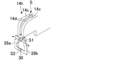
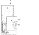
本発明の実施の形態に係る部品供給装置としてのネジ供給装置10は、図1に示すように、ねじ山が形成された軸部S1とその一端に設けた頭部S2とからなる多数のネジが供給され、底部に、供給されたネジSの頭部S2を上にして一列に並べて、図1の紙面左方に送るための略水平に設定されたガイド部材14を備えたネジ整列用ボックス20を有する部品整列部としてのネジ整列部21と、ガイド部材14によって送られてきた最前位置のネジSを受け取って、該ネジSを作業者がネジ供給装置10の外部に取り出すことができるようにする部品取出し部としてのネジ取出し部16と、を有する。
[First Embodiment]
As shown in FIG. 1, a
〔部品整列部(ネジ調整部)〕
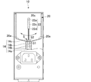
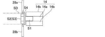
ガイド部材14は、図2に示すように、溝14aを挟んで平行に設定された一対の板状部材14bから構成されている。溝14aの幅は、ネジSの頭部S2の直径より小さく、且つ、ネジSの軸部S1直径より大きくされている。ネジSは、その頭部S2を板状部材14bの上面14cに支持され、軸部S1が溝14aに挿入されて略垂直にされ、ガイド部材用振動発生部18(図1参照)からの振動によって、ネジ取出し部16に向けて送られる。本実施の形態では、ガイド部材14は、一対の板状部材14bから構成しているが、例えば、1つのブロック状の部材に溝を形成したものであっても良い。
[Part alignment section (screw adjustment section)]
As shown in FIG. 2, the
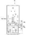
ネジ整列用ボックス20の底部は、図2に示すように、ガイド部材14の両側縁に向けて収束するように傾斜する傾斜底面20aを有している。具体的には、ネジ整列用ボックス20は、図1に示すように、分離壁20bによって上流側室20cと下流側室20dとに分けられており、複数のネジSがまず上流側室20cに供給され、上述のように、ネジSの軸部S1がガイド部材14の溝14aに入り、頭部S2がガイド部材14の上面14cによって支持された状態とされる。しかし、一部のネジSは、その軸S1が溝14aに適正に入った状態とはならずに、その状態のまま、分離壁20bに形成されている通過開口20eを通して下流側室20dに搬送される。上流側室20cと下流側室20dには、ガイド部材14上を横断するように揺動するブラシ22が設けられており、ガイド部材14の溝14aへの挿入が不完全なネジSと係合して(かかわり合って)、同ネジをガイド部材14から一旦はらい外して、該ネジSがネジ整列用ボックス20の傾斜底面20aによって再びガイド部材14上に戻り、その軸部S1がガイド部材14の溝14a内に適正に入るようにしてある。図示の例では、ブラシ22は、上流側室20c及び下流側室20dの上方中央位置を前後方向で延びてネジ整列用ボックス20の前後の壁によって枢動可能(一定角度範囲で回動可能)に支持された枢軸22aと、枢軸22aにネジ22bによって取り外し可能に取り付けられた取付部材22cと、取付部材22cによって枢軸22aに取り付けられた剛毛22dとを有しており、リンク部22gを介して接続された駆動装置22fによって枢軸22aを中心に左右に揺動されるようになっている。
As shown in FIG. 2, the bottom portion of the
〔部品取出し部(ネジ取出し部)〕
以上の構成は、上流室側20cにもブラシ22が取り付けられている点を除いて上述した特許文献に開示されたものと略同じであるが、本実施形態に係るネジ供給装置10は以下に述べるような点を特徴としている。すなわち、ガイド部材14の略水平に延びてきた上面14cが、その前端部分14dすなわちネジ取出し部16のところにおいて、前方に行くに従って下方に湾曲しており、図示の実施形態では、略垂直となるまで略90度にわたり湾曲されて終端又は先端14eに至り、終端又は先端14eから後方に底面14fが延びている。
(配向変換部)
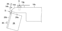
ガイド部材14の底面14fの下方の位置には、略水平にされたネジ支持面24aを備えたネジ支持部材24が設けられている。ネジ支持面24aは、ガイド部材14の底面14fから、ネジSの軸部S1の直径よりも僅かに大きな間隔をあけられており、その前端24bは、ガイド部材14の上面14cの先端14eと垂直方向で略整合した位置とされている。ガイド部材14に沿って進められてきた最前位置のネジSは、ネジの頭部S2が湾曲したガイド部材14の上面14cの湾曲した前端部分14dにガイドされながら、ネジ支持面24a上に落下し、軸部S1がネジ支持面24a上に支持され、ネジの頭部S2がネジ支持面24aの前端24bから前に出た状態とされる。すなわち、この実施形態では、ガイド部材14の上面14cの湾曲した前端部分14dが、ネジSの配向(向き)を変換する配向変換部14hを構成している。ガイド部材14の湾曲した上面14cの先端14eより僅か前方に離れた位置には、垂直にされた板状のガイドカバー26がガイド部材14の上面14cの湾曲した前端部分14dに対向するように設けられている。ネジSが湾曲した上面14cに沿って落下するときには、ネジSはその頭部S2が僅かに前向きに傾くようになって落下するが、この僅かに前向きに傾いた頭部S2の前面S3の下端部分がガイドカバー26の面と接触しながら、ガイド部材14の上面14cの湾曲した前端部分14dとガイドカバー26との間の狭い隙間を案内されることによって、頭部S2の傾きがより大きくなり、頭部S2が湾曲した上面14cの先端14eに達する頃には、ネジSが略水平になるようにされている。また、ガイド部材14の上面14cが、湾曲した前端部分14dに入る直前の水平部分の上方位置には、水平の板状ネジ整列部材14gが設けられており、ネジ整列用ボックス20からガイド部材14に沿って一方向に整列して前進されてきたネジSが、ガイド部材14の湾曲した上面14cに入る前に確実に垂直にされて一列に整列された状態となるようにされている。
[Part extraction part (screw extraction part)]
The above configuration is substantially the same as that disclosed in the above-described patent document except that the
(Orientation conversion part)
At a position below the
(部品支持部材)
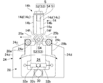
図3に示すように、部品支持部材としてのネジ支持部材24は、ネジの軸部S1の直径よりも広い幅とされたネジ支持面24aの両側縁から側方に離れるに従って下方に傾斜する傾斜側面24cと、該傾斜側面24cに続いて垂直に伸びる垂直側面24dと、ネジ支持面24a上に支持されたネジの頭部S2に隣接した位置となる前端面24fとを有している。ネジ支持面24aの両側は、解放されたネジ取り出し通路25a、25bとされている。このため、以下に述べるように、スクリュードライバの先端をネジ供給装置10の前方からネジ支持面24a上に支持されたネジSの頭部S2の前面S3にアクセスし、スクリュードライバの先端によってネジSの頭部S2を保持し、スクリュードライバをネジSの長手方向軸線に対して側方に(図3の矢印、つまり紙面右方若しくは左方に)動かすことによりネジSをネジ支持面24aからネジ供給装置10の外部に取り出すことができるようにされている。このネジ取り出しの途中において、スクリュードライバの先端がネジSから外れてしまった場合には、該ネジSが傾斜側面24cによって下方に落下するようにされており、次のネジ取り出しの邪魔にならないようにされている。
(Part support member)
As shown in FIG. 3, the
ネジ取出し部16は更に、ガイド部材14の湾曲した上面14cに沿って送られてくるネジSの頭部S2に対してその両側から係合することにより、該ネジSがネジ支持面24aの幅方向中央の位置に保持されるようにするネジ保持部材28(図1、図3)を有する。本実施例では、このネジ保持部材28は、ネジ支持部材24の前端面24fに取り付けたピボット30によって枢着され、前端面24f上を摺動するようにされた左側及び右側ネジ保持部材28a、28bからなる。ここで、枢着とは、凸部分と凹部分をもって回動自在に付けることをいう。また、回動とは、正逆方向に円運動することをいう。左側及び右側ネジ保持部材28a、28bは、それぞれ、ネジの頭部S2の左側及び右側に係合するようになっている。これら左側及び右側ネジ保持部材28a、28bはそれぞれ、ネジ支持部材24の中央に設けられた取付ピン32cとの間に設けられた引っ張りコイルバネ32a、32bにより、それぞれピボット30の周りで時計方向及び反時計方向で付勢(勢いを増加させること)されており、ネジ支持面24a上に支持されたネジSが、上述のようにスクリュードライバによって左側若しくは右側のネジ取り出し通路25a、25bを通して取り出されるときに、ネジSの頭部S2によって押されてネジ取り出し通路25a,25bから退出し、ネジSの取り出しができるようにされている。
Further, the screw take-out
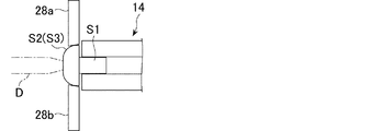
図1乃至図6に示す実施形態では、特に図6に示す如く、ネジSの頭部S2に座金S4が取り付けられており、左側及び右側ネジ保持部材28a、28bは、座金S4の前面を延び頭部S2の両側に係合するようにされている。この場合のネジの頭部S2は、六角形の頭部とされ、ソケットドライバーSDによって該頭部を保持可能なように、左側及び右側ネジ保持部材28a、28bは薄肉とされ、ソケットドライバーSDの先端の係合の邪魔にならないようにしてある。図7は、他の実施形態を示しており、この実施形態では、ネジSが湾曲した前面S3を有する頭部S2を備え、通常のスクリュードライバDによって係合されるようになされており、座金は取り付けられていない。左側及び右側ネジ保持部材28a、28bは、この頭部の湾曲した前面S3と係合して、該ネジSが前方に動くのを阻止するような傾斜した先端面を有するようにされている。
In the embodiment shown in FIGS. 1 to 6, a washer S4 is attached to the head S2 of the screw S, particularly as shown in FIG. 6, and the left and right
図示しないが、ネジ支持面24a上に支持されたネジSを感知するセンサが上下に設けられ、ネジSがネジ支持面24a上に支持されるとガイド部材用振動発生部18の振動が停止されてガイド部材14上のネジSの前進が停止されるようにされ、ネジ支持面24a上からネジSが取り出されると該振動発生部18が振動を再開し、ガイド部材14上のネジSの前進が行われるようにされている。
Although not shown, sensors for detecting the screw S supported on the
〔部品取り出し工具先端ガイド部材〕
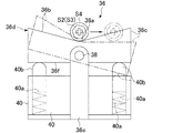
図示の実施形態のおいては、更に、ネジ保持部材28の前側の隣接した位置に、部品取り出し工具としてのスクリュードライバD、SDの先端を、ネジ保持部材28によって保持されたネジSの頭部S2の前面S3に案内する部品取り出し工具先端ガイド部材としてのドライバ先端ガイド部36が設けられている。ドライバ先端ガイド部36は、ネジ保持部材28によって保持されたネジSの頭部S2に整合されて前後方向で延び、ネジSの頭部S2にアクセスしようとするスクリュードライバ先端をネジSの頭部S2の前面S3に導く先端ガイド部36a及び該先端ガイド部36aから左側及び右側に延びV字形のガイド溝を形成する左側及び右側傾斜面36b、36cを有し、前後方向に水平に設定されたピボット38を中心に揺動可能とされているスクリュードライバ先端ガイド部材36dを有する。ドライバ先端ガイド部36は、ネジなどの適宜の手段により当該ネジ供給装置10の静止フレームに固定され、ピボット38の前後端を枢支しているフレーム36eを備えており、フレーム36eには、該スクリュードライバ先端ガイド部材36dの下に間隔をあけてブロック状部材40が取り付けられている。該ブロック状部材40は、その上面に一対の開口が設けられており、該開口内にはコイルバネ40a及びピン40bが設定されている。ピン40bは、水平位置にあるスクリュードライバ先端ガイド部材36dの底面36fに、上記ピボット38の両側位置において接するようになされており、スクリュードライバ先端ガイド部材36dが水平の位置から左右いずれかに傾いたときに、一方のピン40bが押し下げられて、その下にあるコイルバネ40aを圧縮し、当該スクリュードライバ先端ガイド部材36dが元の水平な位置に戻るような付勢力をかけるようになっている。すなわち、スクリュードライバの先端でネジ支持面24a上のネジの頭部S2を保持し、該ネジSの右方又は左方側方へ動かすように該スクリュードライバを動かすときに、スクリュードライバ先端ガイド部材36dが邪魔にならないようにしている。
[Part removal tool tip guide member]
In the illustrated embodiment, the heads of the screws S held by the
[第2実施形態]
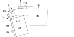
図8及び図9は、第2の実施形態に係るネジ供給装置10を示しており、上述の第1の実施形態におけるものと実質的に同じ部材には同じ参照番号を付してある。図示するように、このネジ供給装置10では、ネジ支持部材24が、ガイド部材14の上面14cの湾曲した前端部分14d(すなわち配向変換部分14h)の下方位置に設けられて斜め下方に傾斜したネジ受取部24gを備えており、ガイド部材14から配向が略水平となるように変換されて供給されるネジSを斜め下方位置まで案内して受け取り支持するようになっている。図示の例では、ネジ受取部24gに沿って案内されるネジSが飛び出さないように、ネジ受取部24gに対して平行にされたカバー部材24hが設けられ、当該ネジ支持部材14の部分で水平にされ、ネジ支持部材24の端部との間にネジ停止部材24iが設けられており、ガイド部材14から供給されたネジSが該ネジ停止部材24iによって停止されるようになっている。ネジ停止部材24iの上下には光学式のセンサ24jが設けられており、第1の実施形態において述べたように、ネジ停止部材24iに達したネジSを感知して、ガイド部材14を振動させる駆動装置22fを停止するようになっている。図9に示すように、この第2の実施形態においては、ネジ支持部材24の前方位置には、ドライバ先端ガイド部36が設けられている。すなわち、該ドライバ先端ガイド部36は、当該ネジ供給装置10の静止フレームにネジで固定されたフレーム36eと、該フレームの前面に固定されたV字形の先端ガイド部材36dとを有しており、スクリュードライバ先端をネジ停止部材24iによって停止されネジ支持部材24によって支持されたネジSの頭部S2にガイドするようになっている。この実施形態では、ネジSを取り出す場合、スクリュードライバをネジSの長手方向軸線に沿って手前に引き出すようにする。
[Second Embodiment]
8 and 9 show the
図10には、ネジ支持部材24のネジ支持面24aが後方に向かうに従って下方に傾斜するようにされ、該ネジ支持面24a上に支持されるネジSが前方に向けて上向きに傾斜した状態で支持される例が示されている。これに伴い、ガイド部材14の前端部分14dの先端14eは、図1に示した実施形態とは異なり、その先端14eが垂直となる前に終端するようになっている。
In FIG. 10, the
図11は、図10の例とは逆に、ネジ支持部材24のネジ支持面24aが後方に向かうに従って上方に傾斜するようにされ、該ネジ支持面24a上に支持されるネジSが前方に向けて下向きに傾斜した状態で支持されるようにした例を示している。
In FIG. 11, contrary to the example of FIG. 10, the
図10及び図11の例から分かるように、ネジ支持部材24のネジ支持面24aはネジ供給の状況に合わせて、適宜の傾斜とすることができる。
As can be seen from the examples of FIGS. 10 and 11, the
以上、本発明をネジ供給装置に適用した場合の実施形態につき述べたが、本発明はこれに限定されるものではなく、ネジ以外のリベットや釘などの軸部及びその一端に設けられた頭部を有する部品の供給にも適用可能であり、また、種々の変形が可能である。変形の例を、上述したネジ供給装置を例にあげて述べれば、例えば、ネジ保持部材28は、枢着されたものではなく、下方からバネ付勢されてネジ取り出し通路25a、25b内にバネ付勢された状態で位置し、取り出されるネジSの頭部S2によって下方に変位可能としたものとすることができる。
As mentioned above, although embodiment about the case where this invention is applied to a screw supply device was described, the present invention is not limited to this, A shaft part other than a screw, such as a rivet and a nail, and a head provided in the end The present invention can be applied to supply of a component having a portion, and various modifications are possible. An example of the deformation will be described by taking the above-described screw supply device as an example. For example, the
ネジ(部品)S;軸部S1;頭部S2;前面S3;座金S4;ネジ供給装置(部品供給装置)10;ガイド部材14;溝14a;板状部材14b;上面14c;前端部分14d;終端又は先端14e;底面14f;板状ネジ整列部材14g;配向変換部14h;ネジ取出し部(部品取り出し部)16;ガイド部材用振動発生部18;ネジ整列用ボックス20;傾斜底面20a;分離壁20b;上流側室20c;下流側室20d;ネジ整列部(部品整列部)21;ブラシ22;枢軸22a;ネジ22b;取付部材22c;剛毛22d;通過開口20e;駆動装置22f;リンク部22g;ネジ支持部材(部品支持部材)24;ネジ支持面(部品支持面)24a;前端24b;傾斜側面24c;垂直側面24d;前端面24f;ネジ受取部24g;カバー部材24h;ネジ停止部材24i;センサ24j;ネジ取り出し通路25a、25b;ガイドカバー26;ネジ保持部材(工具保持部材)28;左側及び右側保持部材28a、28b;ピボット30;引っ張りコイルバネ32a、32b;ドライバ先端ガイド部(部品取り出し工具先端ガイド部)36;先端ガイド部36a;左側傾斜面36b;右側傾斜面36c;スクリュードライバ先端ガイド部材(部品取り出し工具先端ガイド部材)36d;フレーム36e;底面36f;ピボット38;ブロック状部材40;コイルバネ40a、ピン40b Screw (part) S; Shaft S1; Head S2; Front S3; Washer S4; Screw supply device (component supply device) 10; Guide member 14; Groove 14a; Plate member 14b; Or tip 14e; bottom surface 14f; plate screw alignment member 14g; orientation changing portion 14h; screw extraction portion (component extraction portion) 16; guide member vibration generating portion 18; screw alignment box 20; inclined bottom surface 20a; Upstream chamber 20c; downstream chamber 20d; screw alignment portion (part alignment portion) 21; brush 22; pivot 22a; screw 22b; mounting member 22c; bristles 22d; (Component support member) 24; screw support surface (component support surface) 24a; front end 24b; inclined side surface 24c; vertical side surface 24d; front end surface 24f; Screw stop member 24i; sensor 24j; screw take-out passages 25a and 25b; guide cover 26; screw holding member (tool holding member) 28; left and right holding members 28a and 28b; pivot 30; and tension coil springs 32a and 32b Driver tip guide part (part removal tool tip guide part) 36; Tip guide part 36a; Left inclined surface 36b; Right inclined surface 36c; Screw driver tip guide member (part removal tool tip guide member) 36d; Frame 36e; Pivot 38; block-like member 40; coil spring 40a, pin 40b
Claims (10)
該部品整列部により一方向に整列された前記部品の最前位置の部品を外部から取り出し可能とする部品取出し部と、を備え、
該部品取出し部は、
該最前位置の部品を、該部品整列部により一方向に整列された他の部品から離れて下方に動かし、その前記頭部を該部品整列部により一方向に整列された前記部品の前進する向きに向かせる配向変換部と、
該配向変換部により該頭部が該部品整列部により一方向に整列された前記部品の前進する向きに向いた前記部品を受け入れ、外部からの該部品の前記頭部に対するアクセスが可能であるように支持する部品支持部材と、
を有した部品供給装置。 A component aligning portion that moves forward by aligning in one direction with the head of the component comprising a shaft and a head provided at one end of the shaft;
A component take-out part that allows the part at the foremost position of the parts aligned in one direction by the part aligning part to be taken out from the outside,
The parts take-out part
Moving the foremost part downward away from other parts aligned in one direction by the part aligning portion, and moving the head of the part aligned in one direction by the component aligning part An orientation changer directed to
The orientation changing part accepts the part in which the head is oriented in the forward direction of the part aligned in one direction by the part aligning part, so that the part can be accessed from the outside. A component support member that supports
A component supply apparatus having
該部品取出し部は、更に、該部品整列部により一方向に整列された前記部品の前進する方向からのアクセスが可能なように該配向変換部を通して該部品取出し部に送られてくる該部品の頭部の前面を露呈しながら該部品の頭部の両側に係合して該部品の頭部を保持すると共に、該部品を部品支持部材から該側方に動かして取り出すときに、該部品の頭部の動きに伴って、該部品の頭部から外れるように変位可能とされた部品保持部材を有する請求項2に記載の部品供給装置。 The component support member has a component support surface for supporting a shaft portion of a component received by the component support member;
The component take-out unit further passes the orientation changing unit to the component take-out unit so as to allow access from the advancing direction of the component aligned in one direction by the component aligning unit. When the front of the head is exposed and engaged with both sides of the head of the part to hold the head of the part, and when the part is moved from the part support member to the side, The component supply device according to claim 2, further comprising a component holding member that is displaceable so as to be detached from the head of the component as the head moves.
A component take-out tool tip guide member swingable around a pivot extending in the front-rear direction at an adjacent position on the front side of the component holding member and aligned with the head of the component held by the component holding member A tip guide portion that extends in the front-rear direction and guides the tip of the component removal tool to access the head of the component to the front of the head, and a V-shape inclined upward from the tip guide portion toward the left side and the right side When the component removing tool that is guided by the tip guide portion and engaged with the head portion of the component and holds the head portion is displaced to the side. The part removal tool is configured such that the left or right inclined surface is inclined so that the part removal tool tip guide member is tilted around the pivot to allow lateral movement of the part removal tool. The component supply apparatus according to claim 6, further comprising a cutting tool tip guide member.
Priority Applications (1)
| Application Number | Priority Date | Filing Date | Title |
|---|---|---|---|
| JP2011004974A JP5808108B2 (en) | 2011-01-13 | 2011-01-13 | Parts supply device |
Applications Claiming Priority (1)
| Application Number | Priority Date | Filing Date | Title |
|---|---|---|---|
| JP2011004974A JP5808108B2 (en) | 2011-01-13 | 2011-01-13 | Parts supply device |
Publications (2)
| Publication Number | Publication Date |
|---|---|
| JP2012144352A true JP2012144352A (en) | 2012-08-02 |
| JP5808108B2 JP5808108B2 (en) | 2015-11-10 |
Family
ID=46788348
Family Applications (1)
| Application Number | Title | Priority Date | Filing Date |
|---|---|---|---|
| JP2011004974A Expired - Fee Related JP5808108B2 (en) | 2011-01-13 | 2011-01-13 | Parts supply device |
Country Status (1)
| Country | Link |
|---|---|
| JP (1) | JP5808108B2 (en) |
Citations (5)
| Publication number | Priority date | Publication date | Assignee | Title |
|---|---|---|---|---|
| JPS56176140U (en) * | 1980-05-28 | 1981-12-25 | ||
| JPS611378U (en) * | 1985-04-22 | 1986-01-07 | マックス株式会社 | Screw separation device in screw setter |
| JPS61197133A (en) * | 1985-02-28 | 1986-09-01 | Nitto Seiko Co Ltd | Automatic screw tightening machine |
| JPH06144545A (en) * | 1992-11-10 | 1994-05-24 | Nippon Typewriter Co Ltd | Alignedly conveying device for headed part |
| JP2009154971A (en) * | 2007-08-02 | 2009-07-16 | Kofu Seibyo Co Ltd | Screw supply device |
-
2011
- 2011-01-13 JP JP2011004974A patent/JP5808108B2/en not_active Expired - Fee Related
Patent Citations (5)
| Publication number | Priority date | Publication date | Assignee | Title |
|---|---|---|---|---|
| JPS56176140U (en) * | 1980-05-28 | 1981-12-25 | ||
| JPS61197133A (en) * | 1985-02-28 | 1986-09-01 | Nitto Seiko Co Ltd | Automatic screw tightening machine |
| JPS611378U (en) * | 1985-04-22 | 1986-01-07 | マックス株式会社 | Screw separation device in screw setter |
| JPH06144545A (en) * | 1992-11-10 | 1994-05-24 | Nippon Typewriter Co Ltd | Alignedly conveying device for headed part |
| JP2009154971A (en) * | 2007-08-02 | 2009-07-16 | Kofu Seibyo Co Ltd | Screw supply device |
Also Published As
| Publication number | Publication date |
|---|---|
| JP5808108B2 (en) | 2015-11-10 |
Similar Documents
| Publication | Publication Date | Title |
|---|---|---|
| JP5356674B2 (en) | Screw feeder | |
| JP4545731B2 (en) | Bar feeder and bar processing system | |
| JP2009154971A5 (en) | ||
| US20100256819A1 (en) | Variable tape feeder | |
| JP6589134B2 (en) | Stick feeder and component mounting apparatus | |
| JP5707951B2 (en) | Screw feeder | |
| US20160368060A1 (en) | Machine tool | |
| JP5808108B2 (en) | Parts supply device | |
| JP2020064904A (en) | Component supply device and component mounting device | |
| JP4450376B2 (en) | Magazine rack for chip changer | |
| JP6127662B2 (en) | Screw feeding mechanism of connecting screw screw tightening machine and connecting screw screw tightening machine | |
| KR101452663B1 (en) | Screw feeding device | |
| JP4442725B2 (en) | Screw feeder | |
| JP7615306B2 (en) | Feeder and component mounter | |
| JP7590551B2 (en) | Feeder and component mounter | |
| JP7487052B2 (en) | Screw supply device and screw tightening robot | |
| JP5949407B2 (en) | Screw feeder | |
| JP2018167353A (en) | Screw member take-out mechanism of screw member feeder | |
| JP5428112B2 (en) | Bar feeder | |
| JP4255669B2 (en) | Automatic lathe | |
| TWI581915B (en) | Screw guide structure of screw driver for collated screws | |
| JP7648387B2 (en) | Lead component feeder, substrate-related processing machine, and method for mounting lead components on a circuit board | |
| JP2811532B2 (en) | Horizontal screw tightening machine | |
| CN110651537B (en) | Component supply device | |
| TW201607648A (en) | Tool storage apparatus |
Legal Events
| Date | Code | Title | Description |
|---|---|---|---|
| A621 | Written request for application examination |
Free format text: JAPANESE INTERMEDIATE CODE: A621 Effective date: 20140108 |
|
| A977 | Report on retrieval |
Free format text: JAPANESE INTERMEDIATE CODE: A971007 Effective date: 20141117 |
|
| A131 | Notification of reasons for refusal |
Free format text: JAPANESE INTERMEDIATE CODE: A131 Effective date: 20141125 |
|
| A521 | Written amendment |
Free format text: JAPANESE INTERMEDIATE CODE: A523 Effective date: 20150122 |
|
| TRDD | Decision of grant or rejection written | ||
| A01 | Written decision to grant a patent or to grant a registration (utility model) |
Free format text: JAPANESE INTERMEDIATE CODE: A01 Effective date: 20150901 |
|
| A61 | First payment of annual fees (during grant procedure) |
Free format text: JAPANESE INTERMEDIATE CODE: A61 Effective date: 20150908 |
|
| R150 | Certificate of patent or registration of utility model |
Ref document number: 5808108 Country of ref document: JP Free format text: JAPANESE INTERMEDIATE CODE: R150 |
|
| LAPS | Cancellation because of no payment of annual fees |